EP2359985A2 - Schlüssel mit offenem Ende mit Fähigkeit zum schnellen Antreiben eines Werkstücks - Google Patents
Schlüssel mit offenem Ende mit Fähigkeit zum schnellen Antreiben eines Werkstücks Download PDFInfo
- Publication number
- EP2359985A2 EP2359985A2 EP10193961A EP10193961A EP2359985A2 EP 2359985 A2 EP2359985 A2 EP 2359985A2 EP 10193961 A EP10193961 A EP 10193961A EP 10193961 A EP10193961 A EP 10193961A EP 2359985 A2 EP2359985 A2 EP 2359985A2
- Authority
- EP
- European Patent Office
- Prior art keywords
- face
- slide
- force
- jaw
- guiding slot
- Prior art date
- Legal status (The legal status is an assumption and is not a legal conclusion. Google has not performed a legal analysis and makes no representation as to the accuracy of the status listed.)
- Granted
Links
- 230000006835 compression Effects 0.000 claims description 42
- 238000007906 compression Methods 0.000 claims description 42
- 239000002184 metal Substances 0.000 claims description 11
- 239000000463 material Substances 0.000 claims description 5
- 230000001965 increasing effect Effects 0.000 description 6
- 238000013459 approach Methods 0.000 description 4
- 230000002411 adverse Effects 0.000 description 3
- 238000005452 bending Methods 0.000 description 2
- 230000002708 enhancing effect Effects 0.000 description 2
- 230000000694 effects Effects 0.000 description 1
- 230000007257 malfunction Effects 0.000 description 1
- 238000004519 manufacturing process Methods 0.000 description 1
Images


Classifications
-
- B—PERFORMING OPERATIONS; TRANSPORTING
- B25—HAND TOOLS; PORTABLE POWER-DRIVEN TOOLS; MANIPULATORS
- B25B—TOOLS OR BENCH DEVICES NOT OTHERWISE PROVIDED FOR, FOR FASTENING, CONNECTING, DISENGAGING OR HOLDING
- B25B13/00—Spanners; Wrenches
- B25B13/46—Spanners; Wrenches of the ratchet type, for providing a free return stroke of the handle
-
- B—PERFORMING OPERATIONS; TRANSPORTING
- B25—HAND TOOLS; PORTABLE POWER-DRIVEN TOOLS; MANIPULATORS
- B25B—TOOLS OR BENCH DEVICES NOT OTHERWISE PROVIDED FOR, FOR FASTENING, CONNECTING, DISENGAGING OR HOLDING
- B25B13/00—Spanners; Wrenches
- B25B13/02—Spanners; Wrenches with rigid jaws
- B25B13/08—Spanners; Wrenches with rigid jaws of open jaw type
Definitions
- the present invention relates to an open end wrench capable of fast driving a workpiece having a hexagonal driving cross-section, and, more particularly, to an open end wrench capable of fast driving a workpiece without the risk of undesired shifting from the workpiece.
- U.S. 1,320,668 discloses a wrench including a stationary jaw and a movable jaw slideable along a guide surface.
- the movable jaw is forced against an abutment at an outer end of the guide surface by a spring bearing against the stationary jaw.
- An end of the spring is received in a bore in the stationary jaw.
- the other end of the spring is received in another bore in the movable jaw.
- An intermediate portion of the spring is exposed between the stationary jaw and the movable jaw.
- the wrench is turned in a driving rotation direction during which operation the movable jaw remains in contact with the abutment.
- the exposed portion of the spring is liable to bend when compressed and, thus, in friction contact with the end edges of the bores of the stationary and movable jaws, leading to non-smooth compression or even permanent deformation of the spring. Further, the exposed portion of the spring is apt to be contaminated by oil and debris, hindering movement of the movable jaw.
- U.S. Patent No. 3,695,125 discloses an open end ratchet wrench including a head having a fixed jaw and an opposed pawl support portion.
- a pawl and a spring are mounted to an inner side of the pawl support portion.
- the pawl is biased by the spring and slideable between an extended torquing position and a retracted ratcheting position.
- Two side caps are fixed to the head to define a space receiving the pawl and the spring and to prevent disengagement of the pawl and the spring.
- the pawl includes a stop shoulder to prevent the pawl from moving out of the pawl support portion. However, the side caps may separate from the head upon impact, causing disengagement of the pawl from the pawl support portion.
- the pawl merely biased by the spring is still liable to wobble, although there are two side caps on opposite sides of the pawl. Further, the spring is liable to shift from its original position due to impingement to or repeated compression of an exposed portion of the spring, causing malfunction. Further, a gap exists between the side caps and the pawl when the pawl is moved into the space. oil and debris may enter the gap and adversely affect operation.
- U.S. Patent No. 7,024,971 discloses an open end ratchet wrench including first and second stationary jaws.
- the first stationary jaw supports a movable plate.
- a space is sandwiched between two face plates of the first stationary jaw to accommodate the movable plate.
- the movable plate includes two angled slots each receiving a pin extending through the space.
- the wrench further includes a hole receiving a spring that has an end located outside of the hole for biasing the movable plate.
- Each angled slot of the movable plate includes a short section and a long section at an angle to the short section such that the movable plate can move in two stages each having a rectilinear travel.
- the movable plate is liable to get stuck at the intersection of the long and short sections, adversely affecting operation of the wrench in the reverse direction.
- the spring has an exposed section that is liable to bend when the spring is compressed, leading to friction at the end edge of the opening of the hole and resulting in non-smooth compression of the spring or even permanent deformation of the spring.
- the angled slots increase the area of the movable plate or the first stationary jaw, resulting in difficulties in reducing the volume of the open end wrench. Thus, the wrench can not be used in a small space.
- the short section or the longer section would be exposed outside of the first stationary jaw such that debris is apt to accumulate in the slots, adversely affecting rectilinear movement of the movable plate. Further, since the space is open in both sides, the reaction force imparted to the movable plate during driving of a workpiece is completely transmitted to the pins that can not withstand high torque. As a result, the wrench can not be used in high-torque driving operation.
- the present invention solves this need and other problems in the field of reliable structural strength of fast drivable open end wrenches by providing, in a preferred form, an open end wrench capable of fast driving a workpiece.
- the workpiece includes a hexagonal driving cross-section that has first, second, third, fourth, fifth, and sixth sides respectively having first, second, third, fourth, fifth, and sixth force-receiving face portions that are leading face portions of said sides in a first rotating direction of the driving cross-section, and respectively having first, second, third, fourth, fifth, and sixth force-receiving face portions that are leading face portions of the driving cross-section in a second rotating direction.
- the jaw portion of the open end wrench is adapted to a certain size of such a hexagonal driving cross-section, so that reference to the hexagonal driving cross-section in the present specification mean reference to a hexagonal driving cross-section of said certain size.
- the numbering order above of the sides of the driving cross-section of the workpiece and of the face portions of said sides is related to an increasing number in a circumferential direction around the driving cross-section of the workpiece that is assumed to be opposite to a driving rotating direction of the wrench, if further assumed that the numbering order begins with a side that is engaged by the force-applying face of the first jaw of the jaw portion of the wrench.
- the open end wrench includes a body having a handle and a jaw portion formed on an end of the handle. Spaced first and second jaws are formed on an end of the jaw portion opposite to the handle.
- the jaw portion includes a throat intermediate the first and second jaws. The throat and the first and second jaws together define an open end wrenching space adapted for receiving the driving cross-section of the workpiece.
- the jaw portion includes a force-applying face facing the wrenching space and facing a free end of the second jaw. The force-applying face is adapted to correspond to the first force-receiving face portion in the first rotating direction of the driving cross-section of the workpiece.
- the first jaw further includes an arcuate sliding groove facing the wrenching space.
- the sliding groove includes spaced, first and second support wall faces and an arcuate sliding wall face extending between the first and second support wall faces.
- the sliding wall face is free of holes, grooves, and recesses and has an arcuate face.
- a guide element is provided in the sliding groove and has two ends fixed to the first and second support wall faces.
- a slide is slideably received in the sliding groove.
- the slide includes a first side having an arcuate sliding face slideable along the sliding wall face of the sliding groove.
- the sliding face is free of holes, grooves, and recesses.
- the slide further includes a second side opposite to the first side of the slide.
- the second side of the slide includes a first wrenching face located outside of the sliding groove.
- the first wrenching face is adapted to correspond to the fourth force-receiving face in the first rotating direction of the workpiece.
- the slide further includes a top face and a bottom face.
- the slide further includes an arcuate guiding slot extending from the top face through the bottom face.
- the guiding slot is free of holes, grooves, and recesses in the defining wall faces thereof.
- the guide element is received in the guiding slot, preventing the slide from disengaging from the sliding groove.
- the guiding slot includes an abutting end and a pressing end.
- the abutting end is in contact with the guide element when the slide is in an initial position not engaged with the workpiece.
- An elastic device has two ends respectively abutting the guide element and the pressing end of the guiding slot for biasing the slide to the initial position.
- the sliding wall face of the sliding groove is free of holes, grooves, and recesses, the structural strength of the first and second jaws is enhanced. Since the sliding face and the defining wall faces of the guiding slot of the slide are free of holes, grooves, and recesses, the processing costs of the slide can be effectively reduced.
- the slide includes a second wrenching face at an angle of 120 degrees to the first wrenching face.
- the second wrenching face is adapted to correspond to the third force-receiving face in the first rotating direction of the workpiece.
- the slide further includes an recessed portion between the first and second wrenching faces. The recessed portion of the slide is adapted to allow entrance of the third force-receiving face in the second rotating direction of the workpiece.
- the sliding face of the slide has a curvature equal and concentric to that of the sliding wall face of the sliding groove.
- the sliding face of the slide is smoothly slideable along the sliding wall face of the sliding groove.
- the sliding face is adapted to transmit reactive force from the workpiece to the sliding wall face and to avoid concentration of stress on the slide, increasing torque bearing capacity of the slide when the workpiece is driven by the body to rotate.
- the guiding slot has a curvature concentric to that of the sliding wall face of the sliding groove, allowing relative smooth, arcuate sliding between the guiding groove of the slide and the guide element in order to serve for a smooth sliding contact of the sliding face of the slide on the sliding wall face of the sliding groove in each sliding position of the slide.
- the throat includes a push face facing the wrenching space.
- the push face is at an angle of 120 degrees to the force-applying face of the first jaw.
- the push face of the throat is adapted to face the second force-receiving face in the first rotating direction of the workpiece.
- the second jaw includes first and second faces at an angle of 120 degrees to each other. The first and second faces are adapted to correspond respectively to the fourth and third force-receiving faces in the first rotating direction of the workpiece.
- a first recessed portion is formed between the force-applying face of the first jaw and the push face of the throat. The first recessed portion is adapted to allow entrance of the first force-receiving face in the second rotating direction of the workpiece.
- a second recessed portion is formed between the push face of the throat and the second face of the second jaw.
- the first recessed portion is adapted to allow entrance of the second force-receiving face in the second rotating direction of the workpiece.
- the jaw portion further includes a third recessed portion between first and second faces of the second jaw. The third recessed portion is adapted to allow entrance of the third force-receiving face in the second rotating direction of workpiece.
- the elastic device includes an elastic element received in the guiding slot of the slide.
- the first and second support wall faces of the sliding groove are parallel to each other and have a spacing therebetween.
- the top and bottom faces of the slide are parallel to each other and have a height in a height direction of the slide equal to the spacing.
- the guiding slot of the slide has a height in the height direction of the slide equal to the height of the slide.
- the guiding slot has a width in a width direction perpendicular to the height direction of the guiding slot.
- the width of the guiding slot is equal to a diameter of the guide element.
- the height of the guiding slot is larger than 1.5 times the width of the guiding slot.
- the elastic element received in the guiding slot has a height in the height direction of the slide not larger than the height of the guiding slot.
- the height of the elastic element is larger than the width of the guiding slot.
- the height of the elastic element is larger than 0.5 times the height of the guiding slot.
- the elastic device in another preferred forms, includes a base and two elastic elements mounted to a side of the base.
- the first and second support wall faces of the sliding groove are parallel to each other and have a spacing therebetween.
- the top and bottom faces of the slide are parallel to each other and have a height in a height direction of the slide equal to the spacing.
- the guiding slot of the slide has a height in the height direction of the slide equal to the height of the slide.
- the guiding slot has a width in a width direction perpendicular to the height direction of the guiding slot.
- the width of the guiding slot is equal to a diameter of the guide element.
- the height of the guiding slot is larger than 1.5 times the width of the guiding slot.
- the elastic elements are spaced in the height direction of the slide.
- the elastic elements attached to the base have an overall height in the height direction of the slide not larger than the height of the guiding slot.
- the overall height of the elastic elements is larger than the width of the guiding slot.
- the overall height of the elastic elements is larger than 0.5 times the height of the guiding slot.
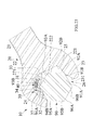
- Body 20 includes a handle 21 and a jaw portion 22 formed on an end of handle 21.
- Jaw portion 22 can hold a hexagonal driving cross-section of a workpiece 90, such as a hexagonal head of a bolt, a nut, or the like.
- the driving cross-section of workpiece 90 includes first, second, third, fourth, fifth, and sixth sides respectively having first, second, third, fourth, fifth, and sixth force-receiving face portions 91A, 92A, 93A, 94A, 95A, and 96A that are leading end portions of said sides in a first rotating direction of the driving cross-section of workpiece 90.
- first, second, third, fourth, fifth, and sixth sides of the driving cross-section of workpiece 90 respectively have first, second, third, fourth, fifth, and sixth force-receiving face portions 91B, 92B, 93B, 94B, 95B, and 96B in a second rotating direction of the driving cross-section of workpiece 90.
- the jaw portion 22 of the open end wrench is adapted to a certain size of such a hexagonal driving cross-section, so that reference to the hexagonal driving cross-section in the present specification mean reference to a hexagonal driving cross-section of said certain size.
- the numbering order above of the sides of the driving cross-section of workpiece 90 and of face portions 91A-96A and 91B-96B of said sides is related in the shown embodiment to an increasing order number in a circumferential direction around the driving cross-section(anticlockwise direction), that is opposite to a driving direction of the wrench, when the jaw portion of the wrench is engaged with the driving cross-section of workpiece 90 as shown, e.g., in FIG. 6 of the drawings, if assumed that the numbering order begins with a side that is engaged by the force-applying face 231 of the first jaw 23 of the jaw portion 22 of the wrench.
- a user can grip the handle 21 and rotate body 20 as well as jaw portion 22 about an axis of the driving cross-section of workpiece 90 to tighten or loosen workpiece 90.
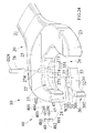
- first and second jaws 23 and 24 are formed on an end of jaw portion 22 opposite to handle 21.
- First and second jaws 23 and 24 can withstand reactive force from workpiece 90.
- First and second jaws 23 and 24 face each other.
- first and second jaws 23 and 24 and jaw portion 22 including throat 25 are integrally formed as a single and inseparable component of the same material to provide jaw portion 22 with excellent structural strength and to increase the torque bearing capacity of jaw portion 22.
- Jaw portion 22 further includes a throat 25 intermediate first and second jaws 23 and 24. Throat 25 and first and second jaws 23 and 24 together define an open end wrenching space 26.
- the driving cross-section of workpiece 90 can enter wrenching space 26 by moving jaw portion 22 in a direction perpendicular to the axis of the driving cross-section of workpiece 90 or by moving jaw portion 22 along the axis of the driving cross-section.
- First jaw 23 includes a force-applying face 231 located on the free end portion of first jaw 24 and facing wrenching space 26 at the opening thereof, thereby facing the free end of second jaw 24.
- Force-applying face 231 is substantially plane and corresponds to first force-receiving face portion 91A in the first rotating direction of workpiece 90, that is the clock-wise driving rotating direction in FIG. 6 of the drawings.
- Force receiving face portion 91A of side 91 of the driving cross-section is a leading end portion of side 91 if workpiece 90 is rotated by the wrench in clockwise direction as shown by an arrow in FIG. 6 .
- Second jaw 24 includes first and second faces 241 and 242 that are substantially plane.
- First face 241 is located on the free end portion of second jaw 24 and faces wrenching space 26 at the opening thereof and faces the portion of first jaw 23 adjacent to throat 25.
- Second face 242 is spaced apart from first face 241 toward throat 25 and faces wrenching space 26 and the free end of first jaw 23.
- First face 241 is inclined with respect to second face 242 by an angle that opens in a direction towards wrenching space 26 and is 120 degrees and is spaced apart by a recessed portion 223 formed into jaw 24, so that first and second faces 241 and 242 correspond respectively to fourth and third force-receiving faces 94A and 93A in the first rotating direction.
- First face 241 of second jaw 24 is substantially parallel with force-applying face 231 of first jaw 23 in the embodiment.
- the free end of second jaw 24 forms a free end face between first face 241 and the rear side of jaw 24, wherein said free end face and first face 241 enclose an over-obtuse angle of about 240 degrees toward wrenching space 26 in the embodiment shown in the drawings.
- Throat 25 includes a substantially plane push face 251 facing wrenching space 26.
- Push face 251 is at an angle of 120 degrees to force-applying face 231 of first jaw 23 and spaced apart therefrom such that push face 251 is parallel to and spaced apart from second force-receiving face portion 92A by a gap in the first rotating direction when workpiece 90 is drivingly engaged in jaw portion 22 ( FIG. 6 ).
- Second face 242 is intermediate first face 241 and push face 251 and push face 251 is intermediate second face 242 and force-applying face 231.
- Jaw portion 22 further includes a first recessed portion 221 between force-applying face 231 of first jaw 23 and push face 251 of throat 25.
- First recessed portion 221 extends into first jaw 23 beyond the level of force-applying face 231 and is defined along a jaw part, that is adjacent to force-applying face 231, by a convex curvature and along a jaw part, that is adjacent to push face 251, by a concave curvature and can receive first force-receiving face portion 91B in the second rotating direction of workpiece 90 and the corner between force-receiving face portions 91B and 92A, when the wrench is rotated in the non-driving direction around the driving cross-section of workkpiece 90 as shown in FIG. 7 .
- Jaw portion 22 further includes a second recessed portion 222 between push face 251 of throat 25 and second face 242 of second jaw 24.
- Second recessed portion 222 is defined by a concave curvature and has an end portion adjacent to push face 251 that extends into throat 25 beyond the level of push face 251 as shown in FIG. 3 .
- Second face 242 is tangent to the other end portion of said concave curvature as shown in Fig. 3 . Therefore, second recessed portion can receive second force-receiving face portion 92B in the second rotating direction of the wrench around workpiece 90 as shown in Fig. 7 that is a non-driving rotating direction of the wrench.
- jaw portion 22 includes a third recessed portion 223 (already mentioned above) between first and second faces 241 and 242 of the second jaw 24.
- Recessed portion 223 is concavely curved.
- First face 241 is tangential to adjacent end portion of recessed portion 223, and the opposite end portion of recessed portion 223 extends into jaw 24 slightly beyond the level of second face 242.
- Third recessed portion 223 can receive third force-receiving face portion 93B in the second rotating direction of the wrench.
- a substantially sickle-shaped arcuate sliding groove 27 having substantially rectangular cross-sections that are closed along three sides is formed in second jaw 24 to extend from first face to about the longitudinal mddle of recessed portion 222, and opens toward wrenching space 26.
- sliding groove 27 is spaced apart from the free end of second jaw 24 by the length of first face 241.
- Sliding groove 27 is defined on both sides thereof by spaced first and second support wall faces 272 and 273, and is defined on the bottom thereof by a concave arcuate sliding wall face 271 extending between first and second support wall faces 272 and 273 in a transverse direction.
- Sliding wall face 271 is free of holes, grooves, recesses, etc, providing a complete arcuate surface along an arc of a circular cylinder throughout the length of sliding groove and enhancing the structural strength of second jaw 24.
- jaw portion 22 can withstand high-torque operation.
- a center of the arcuate sliding wall face 271 is located in wrenching space 26 such that sliding wall face 271 can be easily and rapidly processed with a single cylindrical cutter at low costs while assuring structural strength of jaw portion 22.
- First and second support wall faces 272 and 273 are parallel to each other and have a spacing T27 therebetween.
- a through-hole 274, circular in cross-section, is extended through first and second support wall faces 272 and 273 and open to sliding groove 27.
- Through-hole 274 is located adjacent to throat 25 and receives a cylindrical guide element 28 in the form of a pin. Two ends of guide element 28 are received in two ends of through-hole 274 in first and second support wall faces 272 and 273 to retain guide element 28 in sliding groove 27.
- Guide element 28 has a diameter D28.
- Slide 30 is slideably received in sliding groove 27 and can drive workpiece 90 to rotate in a driving rotation direction of the wrench or can slide around a perimeter of workpiece 90 in an opposite non-driving direction of the wrench without driving workpiece 90 when the slide slides in the sliding groove 27 or is in a non-driving position.
- Slide 30 is substantially arcuate in longitudinal cross section and includes a longitudinal rear side having a convex, arcuate sliding face 31 slideably contacting sliding wall face 271 of sliding groove 27, allowing relative arcuate sliding movement between slide 30 and jaw portion 22 along an arc of a circle.
- Sliding face 31 is free of holes, grooves, recesses, etc, providing a complete arcuate surface and enhancing the structural strength of slide 30.
- slide 30 can withstand high-torque operation.
- Sliding face 31 of slide 30 has a circular arc curvature the same as that of sliding wall face 271 of sliding groove 27 to allow smooth sliding of sliding face 31 on sliding wall face 271. Furthermore, when slide 30 is subjected to reactive force from workpiece 90, the reactive force from the workpiece 90 can be transmitted to sliding wall face 271 through a large area of sliding face 31 due to the same and concentric curvatures. Thus, the force imparted to slide 30 can be distributed, avoiding stress concentration and increasing the torque bearing capacity of slide 30 when workpiece 90 is driven by body 20.
- the other side of slide 30 opposite to sliding face 31 is angled in a recessed manner by about 11 degrees located to project outside of sliding groove 27 in all sliding positions of slide and to project transversely to second jaw 24 beyond each of bottom face of recessed portion 223 and of second face 242 as shown in FIG. 3 , and includes first and second wrenching faces 32 and 33.
- First and second wrenching faces 32 and 33 are adapted to drive workpiece 90 to rotate when the wrench rotates in the driving rotating direction.
- First wrenching face 32 is at an angle of 120 degrees to second wrenching face 33 and spaced apart therefrom by a recessed portion 34 such that first and second wrenching faces 32 and 33 correspond respectively to fourth and third force-receiving faces 94A and 93A in the first rotating direction of workpiece 90, when slide 30 is in a driving position as shown in FIG. 6 .
- first wrenching face 32 of slide 30 is parallel to force-applying face of first jaw 23 when slide 30 is in the driving position, but is displaced, as shown in FIG. 6 , toward the root of second jaw 24 in the driving position of slide by at least half of a side of hexagonal driving cross-section for which the jaw portion 22 is projected.
- the recessed portion 34 is formed between first and second wrenching faces 32 and 33 and is concavely curved to extend beyond the level of second wrenching face 33 into slide 30 in a manner as shown in FIG. 6 .
- the depth of recessed portion 34 is greater adjacent to first wrenching face 32 than along a portion adjacent to second wrenching face 33 that is inclined to second wrenching face 33 by an angle of 15 to 20 degrees, so that recessed portion 34 can receive third force-receiving face portion 93B in the second relative rotating direction of workpiece 90 as shown in FIGS. 7 and 8 .
- slide 30 includes a blunt free end face on the outer free end portion of the slide that projects beyond the outer end of sliding groove 27 and encloses an outer angle of about 120 degrees with first face 241 of second jaw 24 in the driving position of the slide as shown in FIG. 6 .
- a further recessed portion is formed between blunt face of slide and first face 241 of second jaw 24 and can receive fourth force-receiving face portion 94B in the second rotating direction of workpiece 90 as shown in FIGS. 7 to 9 .
- the jaw portion 25 and the slide 30 are adapted to the projected driving cross-section of workpiece 90 in such a manner that the jaw portion 22 inclusive of the slide 30 are designed to be engaged with those portions of the sides of the hexagonal driving cross-section, i.e. with those force-receiving face portions 91A-96A of the hexagonal cross-section of the hexagonal driving cross-section of the workpiece that are leading portions with respect to the transverse center line of the respective side in the driving rotating direction of the wrench, and are further preferably not engaged in the driving position of the slide with the respective trailing portions 91B-96B of the sides of the hexagon in that driving rotating direction of the wrench.
- the driving rotating direction of the wrench is assumed in the drawings to be a clockwise rotating direction as shown in FIG.
- the wrench could be turned with respect to workpiece 90 by 180 degrees in a manner that first jaw 23 is on the left side and second jaw 24 with slide 30 is of the right side of workpiece 90 so that the driving rotating direction would be an anticlockwise direction for loosening the workpiece 90.
- the leading portions of the sides of the driving cross-section of workpiece would now be the force-receiving face portions 91B-96B, while receiving face portions 91A-96B would now are trailing portions.
- the jaw portion 22 of the wrench inclusive of the slide 30 slide is in contact with the driving cross-section of the workpiece 90 in the driving position of the slide 30 shown in FIGS. 6 and 11 with three force-receiving face portions of the sides 91-96 of the hexagonal driving cross-section of workpiece 90 only, wherein said three force-receiving face portions are leading face portions in the respective driving rotating direction of the wrench, i.e. portions 91A, 93A and 94A in the case that the driving rotating direction is clockwise.
- Slide 30 further includes a top face 301 and a bottom face 302 respectively at upper and lower sides thereof.
- First and second wrenching faces 32 and 33 extend transversely between top and bottom faces 301 and 302.
- Top and bottom faces 301 and 302 are parallel to each other and respectively in contact with first and second support wall faces 272 and 273 of sliding groove 27.
- Slide 30 has a height H30 between top and bottom faces 301 and 302 in a height direction. Ignoring the tolerance, height H30 of slide 30 is the same as spacing T27 of sliding groove 27.
- top and bottom faces 301 and 302 of slide 30 to be symmetrically supported by first and second support wall faces 272 and 273 of sliding groove 27, avoiding wobbling of slide 30 while sliding in sliding groove 27 along an arcuate path and increasing operational stability of open end wrench 10.
- Slide 30 further includes a guiding slot 35 extending from top face 301 through bottom face 302.
- Guiding slot 35 is arcuate in longitudinal cross section and has a curvature smaller than and concentric to the curvature of sliding wall face 271 of sliding groove 27. Since guiding slot 35 extends from top face 301 through bottom face 302, a height H35 of guiding slot 35 in the height direction of slide 30 is the same as height H30 of slide 30.
- guiding slot 35 has a width W35 (between inner and outer arcuate surfaces thereof) in a width direction perpendicular to the height direction of slide 30. Namely, width W35 is equal to a difference between a radius of the outer arcuate surface and a radius of the inner arcuate surface of guiding slot 35.
- width W35 of guiding slot 35 is the same as diameter D28 of guide element 28.
- Height H35 of guiding slot 35 is larger than 1.5 times width W35 of guiding slot 35 (i.e., width W35 of guiding slot 35 is smaller than 0.66 times height H35 of guiding slot 35.
- height H35 of guiding slot 35 is larger than two times width W35 of guiding slot 35 (i.e., width W35 of guiding slot 35 is smaller than 0.5 times height H35 of guiding slot 35).
- Guiding slot 35 receives guide element 28 to prevent slide 30 from disengaging from sliding groove 27. Since the curvature of sliding face 31 of slide 30 and sliding wall face 271 of sliding groove 27 are concentric to those of guiding slot 35, smooth sliding movement between guiding slot 35 of slide 30 and guide element 28 in sliding groove 27 is assured. Undesired interference between slide 30, guide element 28, and sliding wall face 271 is avoided.
- Guiding slot 35 further includes an abutting end 351 and a pressing end 352.
- abutting end 351 is in contact with guide element 28, and pressing end 352 is in contact with elastic device 40. Since all of the defining surfaces of guiding slot 35 are free of holes, grooves, recesses, etc, stress concentration is avoided, and the structural strength of slide 30 is assured. Thus, slide 30 can withstand high-torque operation. Furthermore, since sliding face 31 and all of the defining surfaces of guiding slot 35 of slide 30 are free of holes, grooves, recesses, etc, the manufacturing costs of slide 30 can be reduced.
- Elastic device 40 has two ends respectively abutting guide element 28 and pressing end 352 of guiding slot 35 for returning slide 30 to its initial position.
- Elastic device 40 includes in a first embodiment shown in FIGS. 2 to 11 an elastic element 41 mounted in guiding slot 35 of slide 30. After mounting, elastic element 41 is completely received in guiding slot 35 (see FIG. 4 ).
- Elastic element 41 has a height H40 in the height direction of slide 30 not larger than height H35 but larger than width W35 of guiding slot 35. Furthermore, height H40 of elastic element 41 is larger than 0.5 times height H35 of guiding slot 35. Thus, rotation of elastic element 41 in guiding slot 35 is avoided, preventing slide 30 from shifting from its initial position after returning.
- elastic element 41 is a resilient plate having Z-shaped cross sections. At least one force-storing unit 401 is provided between two ends of elastic element 41. Each force-storing unit 401 (see FIG. 2 ) is in the form of a metal plate having substantially V-shaped cross sections. Each force-storing unit 401 includes first and second legs 402 and 403 and a compression section 404 between first and second legs 402 and 403. Compression section 404 can store energy when first and second legs 402 and 403 are compressed, providing force-storing unit 401 with elastic returning function. First leg 402 of each force-storing unit 401 is connected to second leg 403 of an adjacent force-storing unit 401. Thus, compression section 404 of each force-storing unit 401 possesses elastic returning function. First leg 402 on an end of elastic element 41 abuts guide element 28, and second leg 403 on the other end of elastic element 41 abuts pressing end 352 of guiding slot 35. Thus, slide 30 can be automatically returned to its natural, initial position.
- FIGS. 5 and 6 show rotation of open end wrench 10 according to the preferred teachings of the present invention in the driving rotation direction towards first jaw 23 (the clockwise direction in FIG. 6 ) to drive workpiece 90.
- workpiece 90 is firstly entered wrenching space 26 with force-applying face 231 of first jaw 23 of jaw portion 22 abutting first force-receiving face 91A in the first rotating direction (clockwise) of workpiece 90 and with first wrenching face 32 of slide 30 abutting fourth force-receiving face 94A in the first rotating direction of workpiece 90.
- fourth force-receiving face 94A in the first rotating direction of workpiece 90 is parallel to first force-receiving face 91A in the first rotating direction, to make first wrenching face 32 of slide 30 be in surface contact with fourth force-receiving face 94A in the first rotating direction, elastic device 40 in slide 30 is compressed and deformed to move slide 30 along the arcuate path such that first wrenching face 32 of slide 30 can automatically abut fourth force-receiving face 94A in the first rotating direction while first wrenching face 32 of slide 30 is substantially parallel to force-applying face 231 of first jaw 23.
- the user can drive handle 21 in the clockwise direction to rotate jaw portion 22 about the center of workpiece 90.
- the force applied by the user is transmitted through force-applying face 231 of first jaw 23 to first force-receiving face 91A in the first rotating direction of workpiece 90.
- the force applied by the user is transmitted through first wrenching face 32 of slide 30 to fourth force-receiving face 94A in the first rotating direction of workpiece 90.
- workpiece 90 rotates together with jaw portion 22.
- first jaw 23 and jaw portion 22 are integrally formed of the same material, force-applying face 231 of first jaw 23 can effectively withstand the reactive force from first force-receiving face 91A in the first rotating direction of workpiece 90. Furthermore, since second jaw 24 and jaw portion 22 are integrally formed of the same material and since sliding face 31 of slide 30 and sliding wall face 271 of sliding groove 27 are free of holes, grooves, recesses, etc and have the same curvature and are in surface contact with each other, first wrenching face 32 of slide 30 can effectively withstand the reactive force from fourth force-receiving face 94A in the first rotating direction of workpiece 90. Thus, open end wrench 10 according to the preferred teachings of the present invention can withstand high-torque operation.
- second wrenching face 33 of slide 30 abuts third force-receiving face 93A in the first rotating direction of workpiece 90. Since second jaw 24 and jaw portion 22 are integrally formed of the same material and since sliding face 31 of slide 30 and sliding wall face 271 of sliding groove 27 are free of holes, grooves, recesses, etc and have the same curvature and are in surface contact with each other, second wrenching face 33 of slide 30 can effectively withstand the reactive force from third force-receiving face 93A in the first rotating direction of workpiece 90.
- open end wrench 10 according to the preferred teachings of the present invention can withstand high-torque operation.
- FIGS. 7-10 show rotation of open end wrench 10 according to the preferred teachings of the present invention in the opposite, non-driving rotation direction towards second jaw 24 (the counterclockwise direction in FIGS. 7-10 ) without driving workpiece 90.
- jaw portion 22 and handle 21 rotate freely relative to workpiece 90 such that first and second recessed portions 221 and 222 of jaw portion 22 and recessed portion 34 of slide 30 respectively approach first, second, and third force-receiving faces 91B, 92B, and 93B in the second rotating direction of workpiece 90.
- first, second, and third force-receiving faces 91B, 92B, and 93B in the second rotating direction of workpiece 90 enter first and second recessed portions 221 and 222 and recessed portion 34.
- jaw portion 22 can continue its rotation in the counterclockwise direction.
- force-applying face 231 of first jaw 23 moves across first force-receiving face 91B in the second rotating direction of workpiece 90 and approaches second force-receiving face 92A in the first rotating direction of workpiece 90.
- first wrenching face 32 of slide 30 moves across fourth force-receiving face 94B in the second rotating direction of workpiece 90 and approaches fifth force-receiving face 95A in the first rotating direction of workpiece 90.
- second wrenching face 33 of slide 30 also moves across third force-receiving face 93B in the second rotating direction of workpiece 90 and approaches fourth force-receiving face 95A in the first rotating direction of workpiece 90.
- first wrenching face 32 of slide 30 automatically comes in surface contact with fifth force-receiving face 95A in the first rotating direction of workpiece 90 such that first wrenching face 32 of slide 30 is substantially parallel to force-applying face 231 of first jaw 23, reliably positioning jaw portion 22 in the new driving position ready for driving workpiece 90 in the clockwise direction without the need of disengaging workpiece 90 from wrenching space 26 of jaw portion 22 and subsequent reengaging workpiece 90 in wrenching space 26, allowing fast driving of workpiece 90.
- open end wrench 10 returns to the next driving position and is in a state similar to that shown in FIG. 6 .
- the user can again rotate handle 21 in the clockwise direction to make jaw portion 22 rotate about the axis of workpiece 90 and, thus, drive workpiece 90 in the clockwise direction.
- FIGS. 12 and 13 show an open end wrench 10 of a second embodiment according to the preferred teachings of the present invention that is substantially the same as the first embodiment except for elastic device 40.
- Elastic device 40 includes an elastic element 42 mounted in guiding slot 35 of slide 30.
- Elastic element 42 has a height H40 in the height direction of slide 30 not larger than height H35 but larger than width W35 of guiding slot 35. Furthermore, height H40 of elastic element 42 is larger than 0.5 times height H35 of guiding slot 35. Thus, rotation of elastic element 42 in guiding slot 35 is avoided, preventing slide 30 from shifting from its natural, initial position after returning.
- elastic element 42 is an oval helical compression spring. At least one force-storing unit 401 is provided between two ends of elastic element 42. Each force-storing unit 401 is in the form of a metal wire having substantially V-shaped longitudinal sections. Each force-storing unit 401 includes first and second legs 402 and 403 and a compression section 404 between first and second legs 402 and 403. Compression section 404 can store energy when first and second legs 402 and 403 are compressed, providing force-storing unit 401 with elastic returning function. First leg 402 of each force-storing unit 401 is connected to second leg 403 of an adjacent force-storing unit 401. Thus, compression section 404 of each force-storing unit 401 possesses elastic returning function. First leg 402 on an end of elastic element 42 abuts guide element 28, and second leg 403 on the other end of elastic element 42 abuts pressing end 352 of guiding slot 35. Thus, slide 30 can be automatically returned to its natural, initial position.
- FIGS. 14-17 show an open end wrench 10 of a third embodiment according to the preferred teachings of the present invention that is substantially the same as the first embodiment except for elastic device 40.
- Elastic device 40 includes an elastic element 43 mounted in guiding slot 35 of slide 30.
- Elastic element 43 has a height H40 in the height direction of slide 30 not larger than height H35 but larger than width W35 of guiding slot 35. Furthermore, height H40 of elastic element 43 is larger than 0.5 times height H35 of guiding slot 35. Thus, rotation of elastic element 43 in guiding slot 35 is avoided, preventing slide 30 from shifting from its natural, initial position after returning.
- elastic element 43 is in the form of a torsion spring having substantially I-shaped first and second connection units 431 and 432 at two ends thereof.
- a force-storing unit 401 is provided between first and second connection units 431 and 432 and is in the form of a metal wire having substantially V-shaped sections.
- Force-storing unit 401 includes first and second legs 402 and 403 and a compression section 404 between first and second legs 402 and 403. Compression section 404 can store energy when first and second legs 402 and 403 are compressed, providing force-storing unit 401 with elastic returning function.
- First leg 402 of force-storing unit 401 is connected to first connection unit 431.
- Second leg 403 of force-storing unit 401 is connected to second connection unit 432.
- compression section 404 of force-storing unit 401 possesses elastic returning function.
- First connection unit 431 of elastic element 43 abuts guide element 28, and second connection unit 432 of elastic element 43 abuts pressing end 352 of guiding slot 35.
- slide 30 can be automatically returned to its natural, initial position.
- elastic element 43 does not have to include second connection unit 432, and second leg 403 of force-storing unit 301 can directly abut pressing end 352 of guiding slot 35, providing the same returning effect for slide 30.
- FIGS. 18 and 19 show an open end wrench 10 of a fourth embodiment according to the preferred teachings of the present invention that is substantially the same as the first embodiment except for elastic device 40.
- Elastic device 40 includes an elastic element 44 mounted in guiding slot 35 of slide 30.
- Elastic element 44 has a height H40 in the height direction of slide 30 not larger than height H35 but larger than width W35 of guiding slot 35. Furthermore, height H40 of elastic element 44 is larger than 0.5 times height H35 of guiding slot 35. Thus, rotation of elastic element 44 in guiding slot 35 is avoided, preventing slide 30 from shifting from its natural, initial position after returning.
- elastic element 44 is a compression spring having upper and lower helical portions interconnected by a connecting portion 441 with a spacing 442 formed between the upper and lower portions spaced in the height direction of slide 30.
- At least one force-storing unit 401 is provided between two ends of each of the upper and lower portions of elastic element 44.
- Each force-storing unit 401 is in the form of a metal wire having substantially V-shaped sections.
- Each force-storing unit 401 includes first and second legs 402 and 403 and a compression portion 404 between first and second legs 402 and 403. Compression portion 404 can store energy when first and second legs 402 and 403 are compressed, providing force-storing unit 401 with elastic returning function.
- First leg 402 of each force-storing unit 401 is connected to second leg 403 of an adjacent force-storing unit 401.
- compression portion 404 of each force-storing unit 401 possesses elastic returning function.
- First leg 402 on an end of each of the upper and lower portions of elastic element 44 abuts guide element 28.
- Second legs 403 on the other ends of the upper and lower portions of elastic element 44 are interconnected by connecting portion 441 and abut pressing end 352 of guiding slot 35.
- slide 30 can be automatically returned to its initial position.
- FIGS. 20-23 show an open end wrench 10 of a fifth embodiment according to the preferred teachings of the present invention that is substantially the same as the above embodiments except for elastic device 40.
- Elastic device 40 is mounted in guiding slot 35 of slide 30 and includes a base 46 and two elastic elements 45 mounted normal to a side of base 46 and spaced from each other in the height direction of slide 30.
- An overall height H40 of elastic elements 45, that are attached to base 46, in the height direction of slide 30 is not larger than height H35 but larger than width W35 of guiding slot 35.
- the overall height H40 of elastic elements 45 attached to base 46 is larger than 0.5 times height H35 of guiding slot 35.
- each elastic element 45 is a helical compression spring.
- At least one force-storing unit 401 is provided between two ends of each elastic element 45.
- Each force-storing unit 401 is in the form of a metal wire having substantially V-shaped sections.
- Each force-storing unit 401 includes first and second legs 402 and 403 and a compression portion 404 between first and second legs 402 and 403.
- Compression portion 404 can store energy when first and second legs 402 and 403 are compressed, providing force-storing unit 401 with elastic returning function.
- First leg 402 of each force-storing unit 401 is connected to second leg 403 of an adjacent force-storing unit 401.
- compression portion 404 of each force-storing unit 401 possesses elastic returning function.
- Base 46 is received in pressing end 352 of guiding slot 35.
- Two ends of each elastic element 45 respectively abut guide element 28 and base 46 for returning slide 30 to the natural, initial position.
- Two protrusions 461 in the form of cylindrical pegs are formed on a side of base 46 and spaced in the height direction of slide 30. Each protrusion 461 is received in an end of one of elastic elements 45, positioning elastic elements 45 and avoiding operational interference between elastic elements 45 in guiding slot 35.
- a cylindrical rotating face 462 is formed on the other side of base 46 and in sliding contact with round pressing end 352 of guiding slot 35.
- FIGS. 24-27 show an open end wrench 10 of a sixth embodiment according to the preferred teachings of the present invention that is substantially the same as the fifth embodiment except for elastic device 40.
- Elastic device 40 is mounted in guiding slot 35 of slide 30 and includes a base 48 and two parallel helical elastic elements 47 mounted normal to a side of base 48 and spaced from each other in the height direction of slide 30.
- An overall height H40 of elastic elements 47, attached to base 48, in the height direction of slide 30 is not larger than height H35 but larger than width W35 of guiding slot 35.
- the overall height H40 of elastic elements 47 attached to base 48 is larger than 0.5 times height H35 of guiding slot 35.
- each elastic element 47 is a double compression spring. At least one force-storing unit 401 is provided between two ends of each elastic element 47. Each force-storing unit 401 is in the form of a metal wire having substantially V-shaped sections. Each force-storing unit 401 includes first and second legs 402 and 403 and a compression portion 404 between first and second legs 402 and 403. Compression portion 404 can store energy when first and second legs 402 and 403 are compressed, providing force-storing unit 401 with elastic returning function. First leg 402 of each force-storing unit 401 is connected to second leg 403 of an adjacent force-storing unit 401. Thus, compression portion 404 of each force-storing unit 401 possesses elastic returning function.
- Base 48 is received in pressing end 352 of guiding slot 35.
- the two ends of each elastic element 47 respectively abut guide element 28 and base 48 for returning slide 30 to the natural, initial position.
- Two spaced positioning holes 481 are formed in a side of base 48 and spaced in the height direction of slide 30. Each positioning hole 481 receives an end of one of elastic elements 47, positioning elastic elements 47 to be parallel and avoiding operational interference between elastic elements 47 in guiding slot 35.
- a rounded rotating face 482 is formed on the other side of base 48 and in sliding contact with pressing end 352 of guiding slot 35.
Applications Claiming Priority (1)
| Application Number | Priority Date | Filing Date | Title |
|---|---|---|---|
| TW099104830A TW201127558A (en) | 2010-02-12 | 2010-02-12 | Open end wrench capable of fast reciprocatingly turning |
Publications (3)
| Publication Number | Publication Date |
|---|---|
| EP2359985A2 true EP2359985A2 (de) | 2011-08-24 |
| EP2359985A3 EP2359985A3 (de) | 2012-04-04 |
| EP2359985B1 EP2359985B1 (de) | 2013-02-20 |
Family
ID=43837961
Family Applications (1)
| Application Number | Title | Priority Date | Filing Date |
|---|---|---|---|
| EP10193961A Active EP2359985B1 (de) | 2010-02-12 | 2010-12-07 | Schlüssel mit offenem Ende mit Fähigkeit zum schnellen Antreiben eines Werkstücks |
Country Status (5)
| Country | Link |
|---|---|
| US (1) | US8408100B2 (de) |
| EP (1) | EP2359985B1 (de) |
| JP (1) | JP3166546U (de) |
| ES (1) | ES2405983T3 (de) |
| TW (1) | TW201127558A (de) |
Cited By (2)
| Publication number | Priority date | Publication date | Assignee | Title |
|---|---|---|---|---|
| TWI460054B (zh) * | 2012-07-05 | 2014-11-11 | Infar Ind Co Ltd | 防潰角開口快轉扳手 |
| TWI468260B (zh) * | 2012-08-07 | 2015-01-11 | Infar Ind Co Ltd | 防潰角開口快轉扳手(二) |
Families Citing this family (11)
| Publication number | Priority date | Publication date | Assignee | Title |
|---|---|---|---|---|
| TWM440177U (en) * | 2011-03-07 | 2012-11-01 | New Way Tools Co Ltd | Spanner with ratchet function |
| TW201242723A (en) * | 2011-04-29 | 2012-11-01 | Hou-Fei Hu | High-torque quick release reciprocating open-end wrench |
| CN102765067B (zh) * | 2011-05-06 | 2015-05-06 | 胡厚飞 | 高扭力快脱式往复开口扳手 |
| TWI398324B (zh) * | 2011-08-12 | 2013-06-11 | Proxene Tools Co Ltd | 可往復棘輪式之開口扳手 |
| TW201313400A (zh) * | 2011-09-16 | 2013-04-01 | gong-zheng Chen | 活動弧形擒縱顎扳手 |
| US8973470B1 (en) * | 2012-09-28 | 2015-03-10 | The Boeing Company | Wrap-around wrench head |
| CN103820769B (zh) * | 2012-11-16 | 2016-08-31 | 北京北方微电子基地设备工艺研究中心有限责任公司 | 一种反应腔室和mocvd设备 |
| US11541514B2 (en) | 2016-03-23 | 2023-01-03 | Milwaukee Electric Tool Corporation | Locking pliers |
| TWI635932B (zh) * | 2017-02-07 | 2018-09-21 | 胡厚飛 | 高韌性高使用壽命之快速開口扳手 |
| CN111051004B (zh) | 2017-09-11 | 2022-07-22 | 米沃奇电动工具公司 | 具有可移动的增加扭矩钳口部段的锁紧钳 |
| USD910395S1 (en) | 2019-03-11 | 2021-02-16 | Milwaukee Electric Tool Corporation | Pliers |
Citations (3)
| Publication number | Priority date | Publication date | Assignee | Title |
|---|---|---|---|---|
| US1320668A (en) | 1919-11-04 | Johan emil askman | ||
| US3695125A (en) | 1970-10-06 | 1972-10-03 | Cesco Mfg Corp | Open end ratchet wrench |
| US7024971B2 (en) | 2003-03-12 | 2006-04-11 | Stanton John L | Open end ratchet wrench |
Family Cites Families (19)
| Publication number | Priority date | Publication date | Assignee | Title |
|---|---|---|---|---|
| US365019A (en) * | 1887-06-14 | Pipe-wrench | ||
| US385595A (en) * | 1888-07-03 | Pipe-wrench | ||
| US2797600A (en) * | 1955-10-28 | 1957-07-02 | Bud K Beaver | Ratchet type movable jaw wrench |
| DE1118709B (de) * | 1957-12-19 | 1961-11-30 | Bud K Beaver | Schraubenschluessel |
| GB983789A (en) * | 1963-12-27 | 1965-02-17 | Briles Mfg | Ratchet type movable jaw wrench |
| US3641847A (en) * | 1969-11-07 | 1972-02-15 | Billy M Horton | Open end ratchet wrench |
| DE2041855A1 (de) * | 1970-08-24 | 1972-03-02 | Manfred Draeger | Schraubwerkzeug |
| US4158975A (en) * | 1977-08-18 | 1979-06-26 | Desousa Egas J J | Unidirectional gripping open end wrench |
| US4706528A (en) * | 1980-12-15 | 1987-11-17 | Daiya Seiko Kabushiki-Kaisha | Adjustable wrench |
| US4889020A (en) * | 1987-08-31 | 1989-12-26 | Baker David R | Open end ratchet type wrench |
| US5287777A (en) * | 1992-11-03 | 1994-02-22 | Edward Kolodziej | Ratcheting open end wrench |
| US5533428A (en) * | 1994-11-21 | 1996-07-09 | Pradelski; William M. | Ratchetable open-ended wrench |
| US7111529B2 (en) * | 2003-07-25 | 2006-09-26 | Pradelski William W | Ratchetable open-ended wrench |
| TWM310772U (en) * | 2006-09-08 | 2007-05-01 | Ching-An Jiang | Open-end wrench allowing unidirectional operation |
| TWI424904B (zh) * | 2007-08-15 | 2014-02-01 | Stanley Works | 自動調整扳手 |
| US20090193941A1 (en) * | 2008-02-06 | 2009-08-06 | The Stanley Works | Ratchet Wrench |
| US7878095B2 (en) * | 2008-09-25 | 2011-02-01 | Proxene Tools Co., Ltd. | Reciprocatable open end wrench |
| US7827887B2 (en) * | 2008-10-03 | 2010-11-09 | Kung-Cheng Chen | Ratchet wrench |
| US20100147115A1 (en) * | 2008-12-11 | 2010-06-17 | Li-Ju Lee | Unidirectional Ratchet Wrench |
-
2010
- 2010-02-12 TW TW099104830A patent/TW201127558A/zh unknown
- 2010-09-14 US US12/881,243 patent/US8408100B2/en active Active
- 2010-12-07 EP EP10193961A patent/EP2359985B1/de active Active
- 2010-12-07 ES ES10193961T patent/ES2405983T3/es active Active
- 2010-12-27 JP JP2010008422U patent/JP3166546U/ja not_active Expired - Lifetime
Patent Citations (3)
| Publication number | Priority date | Publication date | Assignee | Title |
|---|---|---|---|---|
| US1320668A (en) | 1919-11-04 | Johan emil askman | ||
| US3695125A (en) | 1970-10-06 | 1972-10-03 | Cesco Mfg Corp | Open end ratchet wrench |
| US7024971B2 (en) | 2003-03-12 | 2006-04-11 | Stanton John L | Open end ratchet wrench |
Cited By (2)
| Publication number | Priority date | Publication date | Assignee | Title |
|---|---|---|---|---|
| TWI460054B (zh) * | 2012-07-05 | 2014-11-11 | Infar Ind Co Ltd | 防潰角開口快轉扳手 |
| TWI468260B (zh) * | 2012-08-07 | 2015-01-11 | Infar Ind Co Ltd | 防潰角開口快轉扳手(二) |
Also Published As
| Publication number | Publication date |
|---|---|
| JP3166546U (ja) | 2011-03-10 |
| TW201127558A (en) | 2011-08-16 |
| US20110197720A1 (en) | 2011-08-18 |
| EP2359985B1 (de) | 2013-02-20 |
| EP2359985A3 (de) | 2012-04-04 |
| TWI365793B (de) | 2012-06-11 |
| ES2405983T3 (es) | 2013-06-04 |
| US8408100B2 (en) | 2013-04-02 |
Similar Documents
| Publication | Publication Date | Title |
|---|---|---|
| EP2359985B1 (de) | Schlüssel mit offenem Ende mit Fähigkeit zum schnellen Antreiben eines Werkstücks | |
| EP2383075B1 (de) | Zum schnellen Drehen eines Werkstücks fähiger Gabelschlüssel | |
| EP2517832B1 (de) | Schlüssel mit offenem Ende mit Fähigkeit zum schnellen Antreiben eines Werkstücks | |
| US8408101B2 (en) | Open end wrench capable of fast driving | |
| US8534167B2 (en) | Super high-torque open end wrench capable of fast driving | |
| US8567289B2 (en) | Open end wrench capable of fast driving | |
| EP2633953A1 (de) | Umkehrbarer Ratschenschlüssel | |
| US20150328751A1 (en) | Bias member for reducing ratcheting arc | |
| US9969064B2 (en) | Ratchet tool with stacked switching device | |
| US20060156869A1 (en) | Clamping device for providing high twisting forces and low damage to screw device | |
| US4671142A (en) | Fluid operated wrench | |
| US6341543B1 (en) | Push bar-typed ratchet wrench with high torque strength | |
| US6516691B1 (en) | Racheting tool with a tapered spring positioning member | |
| US20070101832A1 (en) | Ratchet mechanism for hand tools | |
| EP1721707A2 (de) | Bidirektional einstellbarer Schraubenschlüssel mit Rolleninheit | |
| US20090038444A1 (en) | Wrench | |
| US10549406B2 (en) | Open end wrench capable of fast driving and having high toughness and a long service life | |
| US10384333B2 (en) | Ratchet wrench | |
| TWI728817B (zh) | 快速棘輪工具 | |
| EP2457691A1 (de) | Gabelschlüssel geeignet zum schnellen Drehen eines Werkstücks | |
| US20040163498A1 (en) | Structure of a ratchet wrench | |
| EP3744479B1 (de) | Schnell hin- und hergehender schraubenschlüssel | |
| TWI535539B (zh) | Ratchet tool | |
| JP3076338U (ja) | 高捩力推し棒式つめ車スパナ | |
| SK8347Y1 (sk) | Samosvorný západkový vidlicový kľúč |
Legal Events
| Date | Code | Title | Description |
|---|---|---|---|
| PUAI | Public reference made under article 153(3) epc to a published international application that has entered the european phase |
Free format text: ORIGINAL CODE: 0009012 |
|
| PUAI | Public reference made under article 153(3) epc to a published international application that has entered the european phase |
Free format text: ORIGINAL CODE: 0009012 |
|
| AK | Designated contracting states |
Kind code of ref document: A2 Designated state(s): AL AT BE BG CH CY CZ DE DK EE ES FI FR GB GR HR HU IE IS IT LI LT LU LV MC MK MT NL NO PL PT RO RS SE SI SK SM TR |
|
| AX | Request for extension of the european patent |
Extension state: BA ME |
|
| PUAL | Search report despatched |
Free format text: ORIGINAL CODE: 0009013 |
|
| AK | Designated contracting states |
Kind code of ref document: A3 Designated state(s): AL AT BE BG CH CY CZ DE DK EE ES FI FR GB GR HR HU IE IS IT LI LT LU LV MC MK MT NL NO PL PT RO RS SE SI SK SM TR |
|
| AX | Request for extension of the european patent |
Extension state: BA ME |
|
| RIC1 | Information provided on ipc code assigned before grant |
Ipc: B25B 13/08 20060101ALI20120301BHEP Ipc: B25B 13/46 20060101AFI20120301BHEP |
|
| 17P | Request for examination filed |
Effective date: 20120419 |
|
| GRAP | Despatch of communication of intention to grant a patent |
Free format text: ORIGINAL CODE: EPIDOSNIGR1 |
|
| GRAS | Grant fee paid |
Free format text: ORIGINAL CODE: EPIDOSNIGR3 |
|
| GRAA | (expected) grant |
Free format text: ORIGINAL CODE: 0009210 |
|
| AK | Designated contracting states |
Kind code of ref document: B1 Designated state(s): AL AT BE BG CH CY CZ DE DK EE ES FI FR GB GR HR HU IE IS IT LI LT LU LV MC MK MT NL NO PL PT RO RS SE SI SK SM TR |
|
| REG | Reference to a national code |
Ref country code: GB Ref legal event code: FG4D |
|
| REG | Reference to a national code |
Ref country code: CH Ref legal event code: EP |
|
| REG | Reference to a national code |
Ref country code: AT Ref legal event code: REF Ref document number: 597325 Country of ref document: AT Kind code of ref document: T Effective date: 20130315 |
|
| REG | Reference to a national code |
Ref country code: IE Ref legal event code: FG4D |
|
| REG | Reference to a national code |
Ref country code: DE Ref legal event code: R096 Ref document number: 602010005094 Country of ref document: DE Effective date: 20130418 |
|
| REG | Reference to a national code |
Ref country code: SE Ref legal event code: TRGR |
|
| REG | Reference to a national code |
Ref country code: ES Ref legal event code: FG2A Ref document number: 2405983 Country of ref document: ES Kind code of ref document: T3 Effective date: 20130604 |
|
| REG | Reference to a national code |
Ref country code: AT Ref legal event code: MK05 Ref document number: 597325 Country of ref document: AT Kind code of ref document: T Effective date: 20130220 |
|
| REG | Reference to a national code |
Ref country code: NL Ref legal event code: VDEP Effective date: 20130220 |
|
| REG | Reference to a national code |
Ref country code: LT Ref legal event code: MG4D |
|
| PG25 | Lapsed in a contracting state [announced via postgrant information from national office to epo] |
Ref country code: IS Free format text: LAPSE BECAUSE OF FAILURE TO SUBMIT A TRANSLATION OF THE DESCRIPTION OR TO PAY THE FEE WITHIN THE PRESCRIBED TIME-LIMIT Effective date: 20130620 Ref country code: LT Free format text: LAPSE BECAUSE OF FAILURE TO SUBMIT A TRANSLATION OF THE DESCRIPTION OR TO PAY THE FEE WITHIN THE PRESCRIBED TIME-LIMIT Effective date: 20130220 Ref country code: NO Free format text: LAPSE BECAUSE OF FAILURE TO SUBMIT A TRANSLATION OF THE DESCRIPTION OR TO PAY THE FEE WITHIN THE PRESCRIBED TIME-LIMIT Effective date: 20130520 Ref country code: BG Free format text: LAPSE BECAUSE OF FAILURE TO SUBMIT A TRANSLATION OF THE DESCRIPTION OR TO PAY THE FEE WITHIN THE PRESCRIBED TIME-LIMIT Effective date: 20130520 Ref country code: AT Free format text: LAPSE BECAUSE OF FAILURE TO SUBMIT A TRANSLATION OF THE DESCRIPTION OR TO PAY THE FEE WITHIN THE PRESCRIBED TIME-LIMIT Effective date: 20130220 |
|
| PG25 | Lapsed in a contracting state [announced via postgrant information from national office to epo] |
Ref country code: PT Free format text: LAPSE BECAUSE OF FAILURE TO SUBMIT A TRANSLATION OF THE DESCRIPTION OR TO PAY THE FEE WITHIN THE PRESCRIBED TIME-LIMIT Effective date: 20130620 Ref country code: PL Free format text: LAPSE BECAUSE OF FAILURE TO SUBMIT A TRANSLATION OF THE DESCRIPTION OR TO PAY THE FEE WITHIN THE PRESCRIBED TIME-LIMIT Effective date: 20130220 Ref country code: GR Free format text: LAPSE BECAUSE OF FAILURE TO SUBMIT A TRANSLATION OF THE DESCRIPTION OR TO PAY THE FEE WITHIN THE PRESCRIBED TIME-LIMIT Effective date: 20130521 Ref country code: BE Free format text: LAPSE BECAUSE OF FAILURE TO SUBMIT A TRANSLATION OF THE DESCRIPTION OR TO PAY THE FEE WITHIN THE PRESCRIBED TIME-LIMIT Effective date: 20130220 Ref country code: FI Free format text: LAPSE BECAUSE OF FAILURE TO SUBMIT A TRANSLATION OF THE DESCRIPTION OR TO PAY THE FEE WITHIN THE PRESCRIBED TIME-LIMIT Effective date: 20130220 Ref country code: LV Free format text: LAPSE BECAUSE OF FAILURE TO SUBMIT A TRANSLATION OF THE DESCRIPTION OR TO PAY THE FEE WITHIN THE PRESCRIBED TIME-LIMIT Effective date: 20130220 Ref country code: SI Free format text: LAPSE BECAUSE OF FAILURE TO SUBMIT A TRANSLATION OF THE DESCRIPTION OR TO PAY THE FEE WITHIN THE PRESCRIBED TIME-LIMIT Effective date: 20130220 |
|
| PG25 | Lapsed in a contracting state [announced via postgrant information from national office to epo] |
Ref country code: RS Free format text: LAPSE BECAUSE OF FAILURE TO SUBMIT A TRANSLATION OF THE DESCRIPTION OR TO PAY THE FEE WITHIN THE PRESCRIBED TIME-LIMIT Effective date: 20130220 Ref country code: HR Free format text: LAPSE BECAUSE OF FAILURE TO SUBMIT A TRANSLATION OF THE DESCRIPTION OR TO PAY THE FEE WITHIN THE PRESCRIBED TIME-LIMIT Effective date: 20130220 |
|
| PG25 | Lapsed in a contracting state [announced via postgrant information from national office to epo] |
Ref country code: RO Free format text: LAPSE BECAUSE OF FAILURE TO SUBMIT A TRANSLATION OF THE DESCRIPTION OR TO PAY THE FEE WITHIN THE PRESCRIBED TIME-LIMIT Effective date: 20130220 Ref country code: SK Free format text: LAPSE BECAUSE OF FAILURE TO SUBMIT A TRANSLATION OF THE DESCRIPTION OR TO PAY THE FEE WITHIN THE PRESCRIBED TIME-LIMIT Effective date: 20130220 Ref country code: EE Free format text: LAPSE BECAUSE OF FAILURE TO SUBMIT A TRANSLATION OF THE DESCRIPTION OR TO PAY THE FEE WITHIN THE PRESCRIBED TIME-LIMIT Effective date: 20130220 Ref country code: CZ Free format text: LAPSE BECAUSE OF FAILURE TO SUBMIT A TRANSLATION OF THE DESCRIPTION OR TO PAY THE FEE WITHIN THE PRESCRIBED TIME-LIMIT Effective date: 20130220 Ref country code: DK Free format text: LAPSE BECAUSE OF FAILURE TO SUBMIT A TRANSLATION OF THE DESCRIPTION OR TO PAY THE FEE WITHIN THE PRESCRIBED TIME-LIMIT Effective date: 20130220 Ref country code: NL Free format text: LAPSE BECAUSE OF FAILURE TO SUBMIT A TRANSLATION OF THE DESCRIPTION OR TO PAY THE FEE WITHIN THE PRESCRIBED TIME-LIMIT Effective date: 20130220 |
|
| PLBE | No opposition filed within time limit |
Free format text: ORIGINAL CODE: 0009261 |
|
| STAA | Information on the status of an ep patent application or granted ep patent |
Free format text: STATUS: NO OPPOSITION FILED WITHIN TIME LIMIT |
|
| 26N | No opposition filed |
Effective date: 20131121 |
|
| REG | Reference to a national code |
Ref country code: DE Ref legal event code: R097 Ref document number: 602010005094 Country of ref document: DE Effective date: 20131121 |
|
| PG25 | Lapsed in a contracting state [announced via postgrant information from national office to epo] |
Ref country code: LU Free format text: LAPSE BECAUSE OF FAILURE TO SUBMIT A TRANSLATION OF THE DESCRIPTION OR TO PAY THE FEE WITHIN THE PRESCRIBED TIME-LIMIT Effective date: 20131207 |
|
| REG | Reference to a national code |
Ref country code: IE Ref legal event code: MM4A |
|
| REG | Reference to a national code |
Ref country code: FR Ref legal event code: ST Effective date: 20140829 |
|
| PG25 | Lapsed in a contracting state [announced via postgrant information from national office to epo] |
Ref country code: IE Free format text: LAPSE BECAUSE OF NON-PAYMENT OF DUE FEES Effective date: 20131207 |
|
| PG25 | Lapsed in a contracting state [announced via postgrant information from national office to epo] |
Ref country code: FR Free format text: LAPSE BECAUSE OF NON-PAYMENT OF DUE FEES Effective date: 20131231 |
|
| PG25 | Lapsed in a contracting state [announced via postgrant information from national office to epo] |
Ref country code: MC Free format text: LAPSE BECAUSE OF FAILURE TO SUBMIT A TRANSLATION OF THE DESCRIPTION OR TO PAY THE FEE WITHIN THE PRESCRIBED TIME-LIMIT Effective date: 20130220 |
|
| PG25 | Lapsed in a contracting state [announced via postgrant information from national office to epo] |
Ref country code: SM Free format text: LAPSE BECAUSE OF FAILURE TO SUBMIT A TRANSLATION OF THE DESCRIPTION OR TO PAY THE FEE WITHIN THE PRESCRIBED TIME-LIMIT Effective date: 20130220 |
|
| PG25 | Lapsed in a contracting state [announced via postgrant information from national office to epo] |
Ref country code: CY Free format text: LAPSE BECAUSE OF FAILURE TO SUBMIT A TRANSLATION OF THE DESCRIPTION OR TO PAY THE FEE WITHIN THE PRESCRIBED TIME-LIMIT Effective date: 20130220 Ref country code: TR Free format text: LAPSE BECAUSE OF FAILURE TO SUBMIT A TRANSLATION OF THE DESCRIPTION OR TO PAY THE FEE WITHIN THE PRESCRIBED TIME-LIMIT Effective date: 20130220 |
|
| PG25 | Lapsed in a contracting state [announced via postgrant information from national office to epo] |
Ref country code: HU Free format text: LAPSE BECAUSE OF FAILURE TO SUBMIT A TRANSLATION OF THE DESCRIPTION OR TO PAY THE FEE WITHIN THE PRESCRIBED TIME-LIMIT; INVALID AB INITIO Effective date: 20101207 Ref country code: MK Free format text: LAPSE BECAUSE OF FAILURE TO SUBMIT A TRANSLATION OF THE DESCRIPTION OR TO PAY THE FEE WITHIN THE PRESCRIBED TIME-LIMIT Effective date: 20130220 |
|
| REG | Reference to a national code |
Ref country code: CH Ref legal event code: PL |
|
| PG25 | Lapsed in a contracting state [announced via postgrant information from national office to epo] |
Ref country code: MT Free format text: LAPSE BECAUSE OF FAILURE TO SUBMIT A TRANSLATION OF THE DESCRIPTION OR TO PAY THE FEE WITHIN THE PRESCRIBED TIME-LIMIT Effective date: 20130220 |
|
| PG25 | Lapsed in a contracting state [announced via postgrant information from national office to epo] |
Ref country code: LI Free format text: LAPSE BECAUSE OF NON-PAYMENT OF DUE FEES Effective date: 20141231 Ref country code: CH Free format text: LAPSE BECAUSE OF NON-PAYMENT OF DUE FEES Effective date: 20141231 |
|
| PG25 | Lapsed in a contracting state [announced via postgrant information from national office to epo] |
Ref country code: AL Free format text: LAPSE BECAUSE OF FAILURE TO SUBMIT A TRANSLATION OF THE DESCRIPTION OR TO PAY THE FEE WITHIN THE PRESCRIBED TIME-LIMIT Effective date: 20130220 |
|
| PGFP | Annual fee paid to national office [announced via postgrant information from national office to epo] |
Ref country code: ES Payment date: 20230119 Year of fee payment: 13 |
|
| PGFP | Annual fee paid to national office [announced via postgrant information from national office to epo] |
Ref country code: IT Payment date: 20221230 Year of fee payment: 13 |
|
| PGFP | Annual fee paid to national office [announced via postgrant information from national office to epo] |
Ref country code: GB Payment date: 20231220 Year of fee payment: 14 |
|
| PGFP | Annual fee paid to national office [announced via postgrant information from national office to epo] |
Ref country code: SE Payment date: 20231219 Year of fee payment: 14 Ref country code: DE Payment date: 20231117 Year of fee payment: 14 |
|
| PGFP | Annual fee paid to national office [announced via postgrant information from national office to epo] |
Ref country code: ES Payment date: 20240118 Year of fee payment: 14 |