EP2359936B1 - Häcksler - Google Patents
Häcksler Download PDFInfo
- Publication number
- EP2359936B1 EP2359936B1 EP11000300.1A EP11000300A EP2359936B1 EP 2359936 B1 EP2359936 B1 EP 2359936B1 EP 11000300 A EP11000300 A EP 11000300A EP 2359936 B1 EP2359936 B1 EP 2359936B1
- Authority
- EP
- European Patent Office
- Prior art keywords
- housing
- shredder
- inlet opening
- motor
- air inlet
- Prior art date
- Legal status (The legal status is an assumption and is not a legal conclusion. Google has not performed a legal analysis and makes no representation as to the accuracy of the status listed.)
- Active
Links
Images

Classifications
-
- B—PERFORMING OPERATIONS; TRANSPORTING
- B02—CRUSHING, PULVERISING, OR DISINTEGRATING; PREPARATORY TREATMENT OF GRAIN FOR MILLING
- B02C—CRUSHING, PULVERISING, OR DISINTEGRATING IN GENERAL; MILLING GRAIN
- B02C18/00—Disintegrating by knives or other cutting or tearing members which chop material into fragments
- B02C18/06—Disintegrating by knives or other cutting or tearing members which chop material into fragments with rotating knives
- B02C18/16—Details
-
- B—PERFORMING OPERATIONS; TRANSPORTING
- B02—CRUSHING, PULVERISING, OR DISINTEGRATING; PREPARATORY TREATMENT OF GRAIN FOR MILLING
- B02C—CRUSHING, PULVERISING, OR DISINTEGRATING IN GENERAL; MILLING GRAIN
- B02C18/00—Disintegrating by knives or other cutting or tearing members which chop material into fragments
- B02C18/06—Disintegrating by knives or other cutting or tearing members which chop material into fragments with rotating knives
- B02C18/08—Disintegrating by knives or other cutting or tearing members which chop material into fragments with rotating knives within vertical containers
- B02C18/12—Disintegrating by knives or other cutting or tearing members which chop material into fragments with rotating knives within vertical containers with drive arranged below container
-
- B—PERFORMING OPERATIONS; TRANSPORTING
- B02—CRUSHING, PULVERISING, OR DISINTEGRATING; PREPARATORY TREATMENT OF GRAIN FOR MILLING
- B02C—CRUSHING, PULVERISING, OR DISINTEGRATING IN GENERAL; MILLING GRAIN
- B02C18/00—Disintegrating by knives or other cutting or tearing members which chop material into fragments
- B02C18/06—Disintegrating by knives or other cutting or tearing members which chop material into fragments with rotating knives
- B02C18/16—Details
- B02C18/24—Drives
-
- B—PERFORMING OPERATIONS; TRANSPORTING
- B02—CRUSHING, PULVERISING, OR DISINTEGRATING; PREPARATORY TREATMENT OF GRAIN FOR MILLING
- B02C—CRUSHING, PULVERISING, OR DISINTEGRATING IN GENERAL; MILLING GRAIN
- B02C18/00—Disintegrating by knives or other cutting or tearing members which chop material into fragments
- B02C18/06—Disintegrating by knives or other cutting or tearing members which chop material into fragments with rotating knives
- B02C18/16—Details
- B02C2018/162—Shape or inner surface of shredder-housings
-
- B—PERFORMING OPERATIONS; TRANSPORTING
- B02—CRUSHING, PULVERISING, OR DISINTEGRATING; PREPARATORY TREATMENT OF GRAIN FOR MILLING
- B02C—CRUSHING, PULVERISING, OR DISINTEGRATING IN GENERAL; MILLING GRAIN
- B02C2201/00—Codes relating to disintegrating devices adapted for specific materials
- B02C2201/06—Codes relating to disintegrating devices adapted for specific materials for garbage, waste or sewage
- B02C2201/066—Codes relating to disintegrating devices adapted for specific materials for garbage, waste or sewage for garden waste
Definitions
- the invention relates to a shredder specified in the preamble of claim 1 genus.
- the DE 295 14 916 U1 shows a garden shredder, the drive motor is held in a housing.
- the drive motor may have a fan which directs a flow of cooling air to the electric motor in the axial direction.
- the EP 0 948 116 A2 shows a drive motor, which may be provided for example for a lawnmower.
- the drive motor is arranged in a housing, is sucked into the cooling air from above and blown down.
- the US 4,477,029 shows a garden shredder with an electric motor, which is covered to prevent contamination of the electric motor of a cover.
- the invention has for its object to provide a shredder of the generic type, achieved in which a good engine cooling and contamination of the drive motor can be largely avoided.
- the motor housing which is arranged in the housing of the chopper, results in a two-shell construction. Characterized in that the cooling air does not flow directly from the air inlet opening to the drive motor, but first into the interior of the housing and from there into the motor housing, contamination of the drive motor can be largely avoided. The fact that the motor housing is surrounded by cooling air on its outer circumference, also results in a very good cooling effect.
- the air inlet opening is advantageously arranged on a side facing away from an ejection for clippings side of the housing. This position of the air inlet opening the intake of clippings can be largely avoided.
- the air inlet opening is advantageously arranged facing down, wherein at the air inlet opening a grid is arranged. By aligning the air inlet opening down so that cooling air flows up into the air inlet opening, it is achieved that sucked to the grid clippings can automatically fall off again.
- a simple design results when the grid is formed on the housing.
- the housing is advantageously made of plastic.
- a simple construction of the housing results when the housing comprises a bottom plate which closes the housing towards the bottom.
- the air inlet opening is arranged on a recess of the bottom plate.
- the motor housing advantageously has an inlet opening for the intake of cooling air from the housing, which is arranged on the underside of the motor housing and facing the bottom plate.
- a fan wheel driven by the drive motor can be arranged in the region of the inlet opening. Because of that Air inlet opening is disposed on a recess of the bottom plate and the inlet opening facing the motor housing of the bottom plate, a deflection of the cooling air flow is achieved, which leads to a further separation of sucked dirt.
- the cooling air flows directed along the outer circumference of the drive motor and thus ensures good cooling
- the motor housing is advantageously cup-shaped.
- a simple design results when the housing comprises a hood on which the motor housing is formed. For the motor housing thereby no further separate component is needed. This results in a simple structure.
- the bottom plate is connected in particular via a snap connection with the hood. This results in a simple structure.
- An advantageous cooling air flow is achieved when the outlet opening is arranged from the motor housing at the top of the motor housing.
- the outlet opening is arranged in particular in a peripheral region of the chopper between the ejection and the air inlet opening.
- the air flow occurs in particular below a cover of the chopper.
- a knife chamber for the tool is advantageously formed above the housing.
- the outlet opening is arranged in particular adjacent to the bottom of the knife chamber.
- Fig. 1 shows a chopper 1, which is designed as a garden shredder, in perspective view.
- the chopper 1 has two wheels 3 and two feet 4, with which the chopper 1 rests on the ground.
- the shredder has a housing 2 for a in Fig. 1 Not shown drive motor and a feed chute 5 and a Astzu Foodrohr 6.
- a filling opening 8 is arranged for clippings at the upper end.
- the Astzu Switzerland Vietnameserohr 6 is advantageously arranged pivotably on the chopper 1.
- the chopper 1 also has an ejection 7 for clippings, which is covered up by a cover 35. As Fig. 1 shows, the chopper 1 is very low.
- the housing 2 extends into the area of the wheel 3 and has only a small distance to the ground.
- Fig. 2 shows the design of the housing 2 of the chopper 1 in detail.
- the housing 2 has a hood 32, which forms an outer wall 14 of the housing 2.
- the hood 32 also forms an upper side 30 of the housing 2, which bears against a bottom 16 of a knife chamber 9.
- a motor housing 20 is also formed, which is formed as a recess in the top 30 and surrounds a drive motor 10 of the chopper 1 at a distance.
- the drive motor 10 drives a drive shaft 18 rotating, which is approximately perpendicular in the embodiment and at the one in Fig. 2 schematically shown cutter blade 28 is fixed, which forms the tool of the chopper 1.
- the drive motor 10 has a motor flange 27, which is screwed tightly to the bottom 16 of the knife chamber 9 via a plurality of fastening screws 17.
- the knife chamber 9 is followed by the ejection 7.
- the hood 32 is made of plastic and open at the bottom.
- the hood 32 is closed to the ground by a bottom plate 13.
- the bottom plate 13 is fixed via a snap connection 33 on the hood 32.
- the bottom plate 13 is flat and closed.
- the bottom plate 13 has an upwardly directed recess 29, in which an air inlet opening 11 is formed.
- a grid 12 is arranged, which is integrally formed on the bottom plate 13. Due to the recess 29, the air inlet opening 11 is disposed above the bottom plate 13 and has the bottom plate 13 a distance a, which is measured vertically. The air inlet opening 11 is therefore formed above the underside of the housing 2.
- Cooling air is sucked in via the air inlet opening 11 in the direction of the arrow 22.
- the cooling air is deflected in the housing 2 and flows around the motor housing 20, which is arranged completely in the housing 2, on its outside.
- the motor housing 20 On the side facing the bottom plate 13, the motor housing 20 has an inlet opening 21 via which the cooling air in the direction of the arrows 24 into the motor housing 20 flows.
- a fan wheel 34 which is arranged adjacent to the inlet opening 21 in the motor housing 20, is driven in rotation by the drive motor 10.
- Fig. 2 is between the approximately cylindrically shaped drive motor 10 and the Housing wall 15 of the motor housing 20, a gap 31 is formed.
- the motor housing 20 is cup-shaped, and the housing wall 15 is cylindrical or slightly conical. In the gap 31, the cooling air flows along the arrows 25 on the circumference of the drive motor 10 in the longitudinal direction of the drive motor 10 in the direction of the underside of the bottom 16 of the knife chamber.
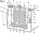
- Fig. 3 shows a section through the housing 2 in a cutting direction perpendicular to the section in FIG Fig. 2 ,
- the ejection 7 is located in the illustration in Fig. 3 in front of the cutting plane. Behind the sectional plane, the air inlet opening 11 is shown.
- Below the bottom 16 of the knife chamber 9 are located on the circumference of the motor housing 20 in a peripheral region between the air inlet opening 11 and the ejection 7 outlet openings 19.
- the cooling air flows in the direction of the arrows 26 to the outside. Accordingly, the cooling air enters through the outlet openings 19 in a region below the in Fig. 1 shown cover 35 from.
- the outlet openings 19 can as in Fig.
- Slats 36 may be provided, which guide the flow obliquely forward in the direction of the ejection 7.
- the drive motor 10 is arranged in a closed up to the inlet opening 21 and the outlet openings 19 motor housing 20, which is arranged in a substantially closed to the air inlet opening 11 formed housing 2.
- This arrangement results in a multiple deflection of the cooling air flow, which avoids the suction of dirt to the drive motor 10 and at the same time achieves effective cooling of the drive motor 10. Due to the upwardly offset arrangement of the air inlet opening 11 on the housing 2 is avoided that clippings or dirt is sucked directly from the ground into the housing 2.
- the proposed training can also be used in shredders 1, which build very low and in which the housing 2 is arranged at a small distance above the ground.
Landscapes
- Engineering & Computer Science (AREA)
- Food Science & Technology (AREA)
- Crushing And Pulverization Processes (AREA)
Description
- Die Erfindung betrifft einen Häcksler der im Oberbegriff des Anspruchs 1 angegebenen Gattung.
- Aus der
US 6,499,873 B1 ist ein Küchenmixer bekannt, bei dem Kühlluft durch seitliche Kühlluftschlitze in ein Gehäuse eingesaugt wird. Die Kühlluft tritt nach unten durch den Boden des Gehäuses wieder aus. - Die
DE 295 14 916 U1 zeigt einen Gartenhäcksler, dessen Antriebsmotor in einem Gehäuse gehalten ist. Der Antriebsmotor kann ein Gebläse besitzen, das in axialer Richtung einen Kühlluftstrom zu dem Elektromotor hin richtet. - Die
EP 0 948 116 A2 zeigt einen Antriebsmotor, der beispielsweise für einen Rasenmäher vorgesehen sein kann. Der Antriebsmotor ist in einem Gehäuse angeordnet, in das Kühlluft von oben angesaugt und nach unten ausgeblasen wird. - Die
US 4,477,029 zeigt einen Gartenhäcksler mit einem Elektromotor, der zur Verhinderung der Verschmutzung des Elektromotors von einer Abdeckung abgedeckt ist. - Aus der
DE 33 39 310 A1 ist ein Gartenhäcksler mit einem Antriebsmotor bekannt, der Kühlluft von unten ansaugt. Bei der Kühlluftansaugung von unten muss vermieden werden, dass Schnittgut mit der Kühlluftöffnung ins Gehäuse des Gartenhäckslers gelangt. Dies ist bei Gartenhäckslern mit geringer Höhe, bei denen zwischen Antriebsmotor und Boden nur wenig Platz ist, nicht ohne Weiteres möglich. - Der Erfindung liegt die Aufgabe zugrunde, einen Häcksler der gattungsgemäßen Art zu schaffen, bei dem eine gute Motorkühlung erreicht und ein Verschmutzen des Antriebsmotors weitgehend vermieden werden kann.
- Diese Aufgabe wird durch einen Häcksler mit den Merkmalen des Anspruchs 1 gelöst.
- Durch das Motorgehäuse, das in dem Gehäuse des Häckslers angeordnet ist, ergibt sich ein zweischaliger Aufbau. Dadurch, dass die Kühlluft nicht direkt von der Lufteintrittsöffnung an den Antriebsmotor strömt, sondern zunächst ins Innere des Gehäuses und von dort in das Motorgehäuse, kann eine Verschmutzung des Antriebsmotors weitgehend vermieden werden. Dadurch, dass das Motorgehäuse an seinem Außenumfang selbst von Kühlluft umströmt ist, ergibt sich außerdem eine sehr gute Kühlwirkung.
- Die Lufteintrittsöffnung ist vorteilhaft an einer einem Auswurf für Schnittgut abgewandten Seite des Gehäuses angeordnet. Durch diese Lage der Lufteintrittsöffnung kann das Ansaugen von Schnittgut weitgehend vermieden werden. Die Lufteintrittsöffnung ist dabei vorteilhaft nach unten gewandt angeordnet, wobei an der Lufteintrittsöffnung ein Gitter angeordnet ist. Durch die Ausrichtung der Lufteintrittsöffnung nach unten derart, dass Kühlluft nach oben in die Lufteintrittsöffnung einströmt, wird erreicht, dass an das Gitter angesaugte Schnittgut selbstständig wieder abfallen kann. Eine einfache Gestaltung ergibt sich, wenn das Gitter am Gehäuse angeformt ist. Dabei ist das Gehäuse vorteilhaft aus Kunststoff ausgebildet. Ein einfacher Aufbau des Gehäuses ergibt sich, wenn das Gehäuse eine Bodenplatte umfasst, die das Gehäuse zum Boden hin verschließt. Die Lufteintrittsöffnung ist an einer Vertiefung der Bodenplatte angeordnet.
- Das Motorgehäuse besitzt vorteilhaft eine Eintrittsöffnung zur Ansaugung von Kühlluft aus dem Gehäuse, die an der Unterseite des Motorgehäuses angeordnet ist und der Bodenplatte zugewandt liegt. Zur Ansaugung kann beispielsweise ein von dem Antriebsmotor angetriebenes Lüfterrad im Bereich der Eintrittsöffnung angeordnet sein. Dadurch, dass die Lufteintrittsöffnung an einer Vertiefung der Bodenplatte angeordnet ist und die Eintrittsöffnung in das Motorgehäuse der Bodenplatte zugewandt liegt, wird eine Umlenkung des Kühlluftstroms erreicht, die zu einer weiteren Abscheidung von angesaugtem Schmutz führt.
- Um zu erreichen, dass die Kühlluft gerichtet am Außenumfang des Antriebsmotors entlang strömt und so eine gute Kühlung bewirkt, ist vorgesehen, dass zwischen der Gehäusewand des Motorgehäuses und dem Antriebsmotor am Umfang des Antriebsmotors ein Zwischenraum für die Kühlluftströmung ausgebildet ist. Das Motorgehäuse ist dabei vorteilhaft topfförmig ausgebildet. Eine einfache Gestaltung ergibt sich, wenn das Gehäuse eine Motorhaube umfasst, an der das Motorgehäuse angeformt ist. Für das Motorgehäuse wird dadurch kein weiteres separates Bauteil benötigt. Es ergibt sich ein einfacher Aufbau. Die Bodenplatte ist insbesondere über eine Schnappverbindung mit der Motorhaube verbunden. Dadurch ergibt sich ein einfacher Aufbau.
- Eine vorteilhafte Kühlluftströmung wird erreicht, wenn die Austrittsöffnung aus dem Motorgehäuse an der Oberseite des Motorgehäuses angeordnet ist. Die Austrittsöffnung ist dabei insbesondere in einem Umfangsbereich des Häckslers zwischen dem Auswurf und der Lufteintrittsöffnung angeordnet. Die Luftströmung tritt dabei insbesondere unterhalb einer Abdeckhaube des Häckslers aus. Oberhalb des Gehäuses ist vorteilhaft eine Messerkammer für das Werkzeug ausgebildet. Die Austrittsöffnung ist dabei insbesondere benachbart zum Boden der Messerkammer angeordnet. Ein einfacher Aufbau ergibt sich, wenn das Gehäuse über mindestens ein Befestigungselement mit dem Boden der Messerkammer verbunden ist.
- Ein Ausführungsbeispiel der Erfindung wird im Folgenden anhand der Zeichnung erläutert. Es zeigen:
- Fig. 1
- eine perspektivische Darstellung eines Häckslers,
- Fig. 2 und Fig. 3
- perspektivische Schnittdarstellungen durch den Häcksler aus
Fig. 1 . -
Fig. 1 zeigt einen Häcksler 1, der als Gartenhäcksler ausgebildet ist, in perspektivischer Darstellung. Der Häcksler 1 besitzt zwei Räder 3 sowie zwei Standfüße 4, mit denen der Häcksler 1 auf dem Boden aufsteht. Der Häcksler besitzt ein Gehäuse 2 für einen inFig. 1 nicht gezeigten Antriebsmotor sowie einen Zuführschacht 5 und ein Astzuführrohr 6. Am Zuführschacht 5 ist am oberen Ende eine Einfüllöffnung 8 für Schnittgut angeordnet. Das Astzuführrohr 6 ist vorteilhaft schwenkbar am Häcksler 1 angeordnet. Der Häcksler 1 besitzt außerdem einen Auswurf 7 für Schnittgut, der nach oben von einer Abdeckhaube 35 abgedeckt ist. WieFig. 1 zeigt, ist der Häcksler 1 sehr niedrig ausgebildet. Das Gehäuse 2 reicht bis in den Bereich des Rads 3 und besitzt nur einen geringen Abstand zum Boden. -
Fig. 2 zeigt die Gestaltung des Gehäuses 2 des Häcksler 1 im Einzelnen. Das Gehäuse 2 besitzt eine Motorhaube 32, die eine Außenwand 14 des Gehäuses 2 bildet. Die Motorhaube 32 bildet außerdem eine Oberseite 30 des Gehäuses 2, die an einem Boden 16 einer Messerkammer 9 anliegt. An der Motorhaube 32 ist außerdem ein Motorgehäuse 20 angeformt, das als Vertiefung in der Oberseite 30 ausgebildet ist und das einen Antriebsmotor 10 des Häckslers 1 mit Abstand umgibt. Der Antriebsmotor 10 treibt eine Antriebswelle 18 rotierend an, die im Ausführungsbeispiel etwa senkrecht steht und an der eine inFig. 2 schematisch gezeigte Messerscheibe 28 festgelegt ist, die das Werkzeug des Häckslers 1 bildet. Der Antriebsmotor 10 besitzt einen Motorflansch 27, der über mehrere Befestigungsschrauben 17 am Boden 16 der Messerkammer 9 festgeschraubt ist. An die Messerkammer 9 schließt sich der Auswurf 7 an. - Die Motorhaube 32 ist aus Kunststoff hergestellt und nach unten hin offen. Die Motorhaube 32 wird zum Boden hin von einer Bodenplatte 13 verschlossen. Wie
Fig. 2 auch zeigt, ist die Bodenplatte 13 über eine Schnappverbindung 33 an der Motorhaube 32 festgelegt. Unterhalb des Motorgehäuses 20 ist die Bodenplatte 13 eben und geschlossen ausgebildet. An der dem Auswurf 7 gegenüberliegenden Seite des Motorgehäuses 20 besitzt die Bodenplatte 13 eine nach oben gerichtete Vertiefung 29, in der eine Lufteintrittsöffnung 11 ausgebildet ist. An der Lufteintrittsöffnung 11 ist ein Gitter 12 angeordnet, das an der Bodenplatte 13 angeformt ist. Aufgrund der Vertiefung 29 ist die Lufteintrittsöffnung 11 oberhalb der Bodenplatte 13 angeordnet und besitzt zur Bodenplatte 13 einen Abstand a, der senkrecht gemessen ist. Die Lufteintrittsöffnung 11 ist demnach oberhalb der Unterseite des Gehäuses 2 ausgebildet. - Über die Lufteintrittsöffnung 11 wird Kühlluft in Richtung des Pfeils 22 angesaugt. Die Kühlluft wird im Gehäuse 2 umgelenkt und umströmt das vollständig im Gehäuse 2 angeordnete Motorgehäuse 20 an seiner Außenseite. Die Kühlluft strömt, wie durch den Pfeil 23 verdeutlicht ist, in den Bereich zwischen Motorgehäuse 20 und Bodenplatte 13. An der der Bodenplatte 13 zugewandten Seite besitzt das Motorgehäuse 20 eine Eintrittsöffnung 21, über die die Kühlluft in Richtung der Pfeile 24 in das Motorgehäuse 20 einströmt. Zur Förderung der Kühlluft dient ein benachbart zur Eintrittsöffnung 21 im Motorgehäuse 20 angeordnetes Lüfterrad 34, das vom Antriebsmotor 10 rotierend angetrieben ist. Wie
Fig. 2 zeigt, ist zwischen dem etwa zylindrisch ausgebildeten Antriebsmotor 10 und der Gehäusewand 15 des Motorgehäuses 20 ein Zwischenraum 31 gebildet. Das Motorgehäuse 20 ist topfförmig ausgebildet, und die Gehäusewand 15 verläuft zylindrisch oder leicht konisch. In dem Zwischenraum 31 strömt die Kühlluft entlang der Pfeile 25 am Umfang des Antriebsmotors 10 in Längsrichtung des Antriebsmotors 10 in Richtung auf die Unterseite des Bodens 16 der Messerkammer 9. -
Fig. 3 zeigt einen Schnitt durch das Gehäuse 2 in einer Schnittrichtung senkrecht zum Schnitt inFig. 2 . Der Auswurf 7 befindet sich bei der Darstellung inFig. 3 vor der Schnittebene. Hinter der Schnittebene ist die Lufteintrittsöffnung 11 gezeigt. Unterhalb des Bodens 16 der Messerkammer 9 befinden sich am Umfang des Motorgehäuses 20 in einem Umfangsbereich zwischen der Lufteintrittsöffnung 11 und dem Auswurf 7 Austrittsöffnungen 19. Durch die Austrittsöffnungen 19 strömt die Kühlluft in Richtung der Pfeile 26 nach außen. Durch die Austrittsöffnungen 19 tritt die Kühlluft demnach in einem Bereich unterhalb der inFig. 1 gezeigten Abdeckhaube 35 aus. An den Austrittsöffnungen 19 können wie inFig. 3 gezeigt, Lamellen 36 vorgesehen sein, die die Strömung schräg nach vorne in Richtung auf den Auswurf 7 leiten. Der Antriebsmotor 10 ist in einem bis auf die Eintrittsöffnung 21 und die Austrittsöffnungen 19 geschlossenen Motorgehäuse 20 angeordnet, das in einen im Wesentlichen bis auf die Lufteintrittsöffnung 11 ebenfalls geschlossen ausgebildeten Gehäuse 2 angeordnet ist. Durch diese Anordnung ergibt sich eine mehrfache Umlenkung des Kühlluftstroms, die das Ansaugen von Verschmutzungen zum Antriebsmotor 10 vermeidet und gleichzeitig eine effektive Kühlung des Antriebsmotors 10 erreicht. Durch die nach oben versetzte Anordnung der Lufteintrittsöffnung 11 am Gehäuse 2 wird vermieden, dass Schnittgut oder Schmutz direkt vom Boden in das Gehäuse 2 angesaugt wird. Dadurch ist die vorgeschlagene Ausbildung auch bei Häckslern 1 einsetzbar, die sehr niedrig bauen und bei denen das Gehäuse 2 in geringem Abstand über dem Boden angeordnet ist.
Claims (13)
- Häcksler mit einem Antriebsmotor, der mindestens ein Werkzeug rotierend antreibt, wobei der Häcksler (1) ein Gehäuse (2) besitzt, das mindestens eine Lufteintrittsöffnung (11) für Kühlluft für den Antriebsmotor (10) aufweist, wobei der Antriebsmotor (10) in einem inneren Motorgehäuse (20) angeordnet ist, das vollständig in dem Gehäuse (2) des Häckslers (1) angeordnet ist und in das Kühlluft aus dem Gehäuse (2) angesaugt wird, wobei das Gehäuse (2) eine Bodenplatte (13) umfasst, die das Gehäuse (2) zum Boden hin verschließt,
dadurch gekennzeichnet, dass die Lufteintrittsöffnung (11) an einer Vertiefung (29) der Bodenplatte (13) angeordnet ist. - Häcksler nach Anspruch 1,
dadurch gekennzeichnet, dass der Häcksler (1) einen Auswurf (7) für Schnittgut besitzt und dass die Lufteintrittsöffnung (11) an der dem Auswurf (7) abgewandten Seite des Gehäuses (2) angeordnet ist. - Häcksler nach Anspruch 1 oder 2,
dadurch gekennzeichnet, dass die Lufteintrittsöffnung (11) nach unten gewandt angeordnet ist und dass an der Lufteintrittsöffnung (11) ein Gitter (12) angeordnet ist. - Häcksler nach Anspruch 3,
dadurch gekennzeichnet, dass das Gitter (12) am Gehäuse (2) angeformt ist. - Häcksler nach einem der Ansprüche 1 bis 4,
dadurch gekennzeichnet, dass das Motorgehäuse (20) eine Eintrittsöffnung (21) zur Ansaugung von Kühlluft aus dem Gehäuse (2) besitzt, die an der Unterseite des Motorgehäuses (20) angeordnet ist und der Bodenplatte (13) zugewandt liegt. - Häcksler nach einem der Ansprüche 1 bis 5,
dadurch gekennzeichnet, dass zwischen der Gehäusewand (15) des Motorgehäuses (20) und dem Antriebsmotor (10) am Umfang des Antriebsmotors (10) ein Zwischenraum (31) für die Kühlluftströmung ausgebildet ist. - Häcksler nach einem der Ansprüche 1 bis 6,
dadurch gekennzeichnet, dass das Motorgehäuse (20) topfförmig ausgebildet ist. - Häcksler nach einem der Ansprüche 1 bis 7,
dadurch gekennzeichnet, dass das Gehäuse (2) eine Motorhaube (32) umfasst, an der das Motorgehäuse (20) angeformt ist. - Häcksler nach Anspruch 8,
dadurch gekennzeichnet, dass die Bodenplatte (13) über eine Schnappverbindung (33) mit der Motorhaube (32) verbunden ist. - Häcksler nach einem der Ansprüche 1 bis 9,
dadurch gekennzeichnet, dass eine Austrittsöffnung (19) für Kühlluft aus dem Motorgehäuse (20) an der Oberseite des Motorgehäuses (20) angeordnet ist. - Häcksler nach Anspruch 10,
dadurch gekennzeichnet, dass die Austrittsöffnung (19) in einem Umfangsbereich des Häckslers (1) zwischen dem Auswurf (7) und der Lufteintrittsöffnung (11) angeordnet ist. - Häcksler nach Anspruch 10 oder 11,
dadurch gekennzeichnet, dass oberhalb des Gehäuses (2) eine Messerkammer (9) für das Werkzeug ausgebildet ist, und dass die Austrittsöffnung (19) benachbart zum Boden (16) der Messerkammer (9) angeordnet ist. - Häcksler nach Anspruch 12,
dadurch gekennzeichnet, dass das Gehäuse (2) über mindestens ein Befestigungselement mit dem Boden (16) der Messerkammer (9) verbunden ist.
Applications Claiming Priority (1)
| Application Number | Priority Date | Filing Date | Title |
|---|---|---|---|
| DE202010001505U DE202010001505U1 (de) | 2010-01-29 | 2010-01-29 | Häcksler |
Publications (4)
| Publication Number | Publication Date |
|---|---|
| EP2359936A2 EP2359936A2 (de) | 2011-08-24 |
| EP2359936A3 EP2359936A3 (de) | 2017-01-25 |
| EP2359936B1 true EP2359936B1 (de) | 2018-11-14 |
| EP2359936B8 EP2359936B8 (de) | 2019-01-02 |
Family
ID=43495700
Family Applications (1)
| Application Number | Title | Priority Date | Filing Date |
|---|---|---|---|
| EP11000300.1A Active EP2359936B8 (de) | 2010-01-29 | 2011-01-15 | Häcksler |
Country Status (2)
| Country | Link |
|---|---|
| EP (1) | EP2359936B8 (de) |
| DE (1) | DE202010001505U1 (de) |
Families Citing this family (1)
| Publication number | Priority date | Publication date | Assignee | Title |
|---|---|---|---|---|
| CN112844701A (zh) * | 2019-11-27 | 2021-05-28 | 卓海峰 | 一种制药药物粉碎机及方法 |
Family Cites Families (5)
| Publication number | Priority date | Publication date | Assignee | Title |
|---|---|---|---|---|
| JPS57197044A (en) * | 1981-05-15 | 1982-12-03 | Robuaa Sukotsuto Bonaa Ltd | Finely cutting machine |
| DE3339310A1 (de) | 1983-10-29 | 1985-05-09 | Gloria-Werke H. Schulte-Frankenfeld Gmbh & Co, 4724 Wadersloh | Antriebsvorrichtung fuer einen gartenhaecksler |
| DE29514916U1 (de) * | 1995-09-16 | 1995-11-09 | AS-Motor GmbH u. Co KG, 74420 Oberrot | Vorrichtung zum Zerkleinern von Schnittholz und anderen Gartenabfällen |
| AT3546U1 (de) * | 1998-03-31 | 2000-04-25 | Atb Austria Antriebstechnik Ak | Elektromotor mit luftkühlung |
| US6499873B1 (en) * | 2000-11-24 | 2002-12-31 | Quality & Strength Inc. | Fruit/vegetable blender |
-
2010
- 2010-01-29 DE DE202010001505U patent/DE202010001505U1/de not_active Expired - Lifetime
-
2011
- 2011-01-15 EP EP11000300.1A patent/EP2359936B8/de active Active
Non-Patent Citations (1)
| Title |
|---|
| None * |
Also Published As
| Publication number | Publication date |
|---|---|
| EP2359936B8 (de) | 2019-01-02 |
| EP2359936A2 (de) | 2011-08-24 |
| EP2359936A3 (de) | 2017-01-25 |
| DE202010001505U1 (de) | 2011-01-20 |
Similar Documents
| Publication | Publication Date | Title |
|---|---|---|
| EP2371202B1 (de) | Handgeführtes Arbeitsgerät | |
| EP2431132B1 (de) | Handgeführtes Arbeitsgerät | |
| EP2875718B1 (de) | Handgeführtes Arbeitsgerät mit einem Blasrohr | |
| DE102011014068B4 (de) | Handgeführtes Arbeitsgerät | |
| EP2211444B1 (de) | Elektromotor mit Kühlventilatorwirkung | |
| DE102016007205A1 (de) | Ventilatoreinheit | |
| DE102005014348B3 (de) | Pumpe mit Schneidlaufrad und Vorzerkleinerer | |
| DE2451186A1 (de) | Zuckerrohrerntemaschine | |
| DE102005031420A1 (de) | Kombinierte Tauch-/Flachabsaug-Rotationspumpe | |
| DE102013208705A1 (de) | Handhobelmaschine | |
| EP2808553B1 (de) | Elektromotor mit Gebläserad | |
| DE2528332A1 (de) | Grasauswurfvorrichtung an motorisch angetriebenen rasenmaehern | |
| EP2940311B1 (de) | Radialgebläse mit verbesserter anströmkantengeometrie | |
| DE4202195C2 (de) | Motorbetriebenes Handwerkzeug mit integrierter Staubabsaugung | |
| EP3176920A2 (de) | Abdeckvorrichtung für ein elektronikgehäuse eines elektromotors | |
| EP1133910B1 (de) | Lagerschild eines Mähtellers | |
| EP2359936B1 (de) | Häcksler | |
| DE102004039499A1 (de) | Blasaufsatz und Blasgerät für die Garten- und Landschaftspflege | |
| EP3421806B1 (de) | Gebläse | |
| DE10033032C1 (de) | Werkzeugabschirmung für einen Stabmixer | |
| DE19709193B4 (de) | Radialventilator | |
| DE19749337A1 (de) | Häcksler zum Zerkleinern von Halmgut | |
| DE20319363U1 (de) | Mulchmäher | |
| EP0175313B1 (de) | Vorrichtung zum Zerkleinern von Abfall | |
| EP1790431B1 (de) | Spanbrecher mit Absaugvorrichtung |
Legal Events
| Date | Code | Title | Description |
|---|---|---|---|
| PUAI | Public reference made under article 153(3) epc to a published international application that has entered the european phase |
Free format text: ORIGINAL CODE: 0009012 |
|
| AK | Designated contracting states |
Kind code of ref document: A2 Designated state(s): AL AT BE BG CH CY CZ DE DK EE ES FI FR GB GR HR HU IE IS IT LI LT LU LV MC MK MT NL NO PL PT RO RS SE SI SK SM TR |
|
| AX | Request for extension of the european patent |
Extension state: BA ME |
|
| PUAL | Search report despatched |
Free format text: ORIGINAL CODE: 0009013 |
|
| AK | Designated contracting states |
Kind code of ref document: A3 Designated state(s): AL AT BE BG CH CY CZ DE DK EE ES FI FR GB GR HR HU IE IS IT LI LT LU LV MC MK MT NL NO PL PT RO RS SE SI SK SM TR |
|
| AX | Request for extension of the european patent |
Extension state: BA ME |
|
| RIC1 | Information provided on ipc code assigned before grant |
Ipc: B02C 18/12 20060101ALI20161222BHEP Ipc: B02C 18/24 20060101ALI20161222BHEP Ipc: B02C 18/16 20060101AFI20161222BHEP |
|
| STAA | Information on the status of an ep patent application or granted ep patent |
Free format text: STATUS: REQUEST FOR EXAMINATION WAS MADE |
|
| 17P | Request for examination filed |
Effective date: 20170714 |
|
| RBV | Designated contracting states (corrected) |
Designated state(s): AL AT BE BG CH CY CZ DE DK EE ES FI FR GB GR HR HU IE IS IT LI LT LU LV MC MK MT NL NO PL PT RO RS SE SI SK SM TR |
|
| GRAP | Despatch of communication of intention to grant a patent |
Free format text: ORIGINAL CODE: EPIDOSNIGR1 |
|
| STAA | Information on the status of an ep patent application or granted ep patent |
Free format text: STATUS: GRANT OF PATENT IS INTENDED |
|
| INTG | Intention to grant announced |
Effective date: 20171128 |
|
| GRAJ | Information related to disapproval of communication of intention to grant by the applicant or resumption of examination proceedings by the epo deleted |
Free format text: ORIGINAL CODE: EPIDOSDIGR1 |
|
| STAA | Information on the status of an ep patent application or granted ep patent |
Free format text: STATUS: REQUEST FOR EXAMINATION WAS MADE |
|
| GRAS | Grant fee paid |
Free format text: ORIGINAL CODE: EPIDOSNIGR3 |
|
| STAA | Information on the status of an ep patent application or granted ep patent |
Free format text: STATUS: GRANT OF PATENT IS INTENDED |
|
| GRAP | Despatch of communication of intention to grant a patent |
Free format text: ORIGINAL CODE: EPIDOSNIGR1 |
|
| INTC | Intention to grant announced (deleted) | ||
| INTG | Intention to grant announced |
Effective date: 20180412 |
|
| GRAA | (expected) grant |
Free format text: ORIGINAL CODE: 0009210 |
|
| STAA | Information on the status of an ep patent application or granted ep patent |
Free format text: STATUS: THE PATENT HAS BEEN GRANTED |
|
| AK | Designated contracting states |
Kind code of ref document: B1 Designated state(s): AL AT BE BG CH CY CZ DE DK EE ES FI FR GB GR HR HU IE IS IT LI LT LU LV MC MK MT NL NO PL PT RO RS SE SI SK SM TR |
|
| REG | Reference to a national code |
Ref country code: GB Ref legal event code: FG4D Free format text: NOT ENGLISH |
|
| REG | Reference to a national code |
Ref country code: CH Ref legal event code: EP Ref country code: AT Ref legal event code: REF Ref document number: 1064191 Country of ref document: AT Kind code of ref document: T Effective date: 20181115 |
|
| REG | Reference to a national code |
Ref country code: DE Ref legal event code: R096 Ref document number: 502011014991 Country of ref document: DE |
|
| REG | Reference to a national code |
Ref country code: IE Ref legal event code: FG4D Free format text: LANGUAGE OF EP DOCUMENT: GERMAN |
|
| REG | Reference to a national code |
Ref country code: CH Ref legal event code: PK Free format text: BERICHTIGUNG B8 |
|
| RAP2 | Party data changed (patent owner data changed or rights of a patent transferred) |
Owner name: ANDREAS STIHL AG & CO. KG |
|
| REG | Reference to a national code |
Ref country code: NL Ref legal event code: MP Effective date: 20181114 |
|
| REG | Reference to a national code |
Ref country code: LT Ref legal event code: MG4D |
|
| PG25 | Lapsed in a contracting state [announced via postgrant information from national office to epo] |
Ref country code: BG Free format text: LAPSE BECAUSE OF FAILURE TO SUBMIT A TRANSLATION OF THE DESCRIPTION OR TO PAY THE FEE WITHIN THE PRESCRIBED TIME-LIMIT Effective date: 20190214 Ref country code: NO Free format text: LAPSE BECAUSE OF FAILURE TO SUBMIT A TRANSLATION OF THE DESCRIPTION OR TO PAY THE FEE WITHIN THE PRESCRIBED TIME-LIMIT Effective date: 20190214 Ref country code: HR Free format text: LAPSE BECAUSE OF FAILURE TO SUBMIT A TRANSLATION OF THE DESCRIPTION OR TO PAY THE FEE WITHIN THE PRESCRIBED TIME-LIMIT Effective date: 20181114 Ref country code: IS Free format text: LAPSE BECAUSE OF FAILURE TO SUBMIT A TRANSLATION OF THE DESCRIPTION OR TO PAY THE FEE WITHIN THE PRESCRIBED TIME-LIMIT Effective date: 20190314 Ref country code: ES Free format text: LAPSE BECAUSE OF FAILURE TO SUBMIT A TRANSLATION OF THE DESCRIPTION OR TO PAY THE FEE WITHIN THE PRESCRIBED TIME-LIMIT Effective date: 20181114 Ref country code: LT Free format text: LAPSE BECAUSE OF FAILURE TO SUBMIT A TRANSLATION OF THE DESCRIPTION OR TO PAY THE FEE WITHIN THE PRESCRIBED TIME-LIMIT Effective date: 20181114 Ref country code: LV Free format text: LAPSE BECAUSE OF FAILURE TO SUBMIT A TRANSLATION OF THE DESCRIPTION OR TO PAY THE FEE WITHIN THE PRESCRIBED TIME-LIMIT Effective date: 20181114 Ref country code: FI Free format text: LAPSE BECAUSE OF FAILURE TO SUBMIT A TRANSLATION OF THE DESCRIPTION OR TO PAY THE FEE WITHIN THE PRESCRIBED TIME-LIMIT Effective date: 20181114 |
|
| PG25 | Lapsed in a contracting state [announced via postgrant information from national office to epo] |
Ref country code: AL Free format text: LAPSE BECAUSE OF FAILURE TO SUBMIT A TRANSLATION OF THE DESCRIPTION OR TO PAY THE FEE WITHIN THE PRESCRIBED TIME-LIMIT Effective date: 20181114 Ref country code: RS Free format text: LAPSE BECAUSE OF FAILURE TO SUBMIT A TRANSLATION OF THE DESCRIPTION OR TO PAY THE FEE WITHIN THE PRESCRIBED TIME-LIMIT Effective date: 20181114 Ref country code: SE Free format text: LAPSE BECAUSE OF FAILURE TO SUBMIT A TRANSLATION OF THE DESCRIPTION OR TO PAY THE FEE WITHIN THE PRESCRIBED TIME-LIMIT Effective date: 20181114 Ref country code: NL Free format text: LAPSE BECAUSE OF FAILURE TO SUBMIT A TRANSLATION OF THE DESCRIPTION OR TO PAY THE FEE WITHIN THE PRESCRIBED TIME-LIMIT Effective date: 20181114 Ref country code: GR Free format text: LAPSE BECAUSE OF FAILURE TO SUBMIT A TRANSLATION OF THE DESCRIPTION OR TO PAY THE FEE WITHIN THE PRESCRIBED TIME-LIMIT Effective date: 20190215 Ref country code: PT Free format text: LAPSE BECAUSE OF FAILURE TO SUBMIT A TRANSLATION OF THE DESCRIPTION OR TO PAY THE FEE WITHIN THE PRESCRIBED TIME-LIMIT Effective date: 20190314 |
|
| PG25 | Lapsed in a contracting state [announced via postgrant information from national office to epo] |
Ref country code: IT Free format text: LAPSE BECAUSE OF FAILURE TO SUBMIT A TRANSLATION OF THE DESCRIPTION OR TO PAY THE FEE WITHIN THE PRESCRIBED TIME-LIMIT Effective date: 20181114 Ref country code: DK Free format text: LAPSE BECAUSE OF FAILURE TO SUBMIT A TRANSLATION OF THE DESCRIPTION OR TO PAY THE FEE WITHIN THE PRESCRIBED TIME-LIMIT Effective date: 20181114 Ref country code: CZ Free format text: LAPSE BECAUSE OF FAILURE TO SUBMIT A TRANSLATION OF THE DESCRIPTION OR TO PAY THE FEE WITHIN THE PRESCRIBED TIME-LIMIT Effective date: 20181114 Ref country code: PL Free format text: LAPSE BECAUSE OF FAILURE TO SUBMIT A TRANSLATION OF THE DESCRIPTION OR TO PAY THE FEE WITHIN THE PRESCRIBED TIME-LIMIT Effective date: 20181114 |
|
| REG | Reference to a national code |
Ref country code: DE Ref legal event code: R097 Ref document number: 502011014991 Country of ref document: DE |
|
| PG25 | Lapsed in a contracting state [announced via postgrant information from national office to epo] |
Ref country code: MC Free format text: LAPSE BECAUSE OF FAILURE TO SUBMIT A TRANSLATION OF THE DESCRIPTION OR TO PAY THE FEE WITHIN THE PRESCRIBED TIME-LIMIT Effective date: 20181114 Ref country code: RO Free format text: LAPSE BECAUSE OF FAILURE TO SUBMIT A TRANSLATION OF THE DESCRIPTION OR TO PAY THE FEE WITHIN THE PRESCRIBED TIME-LIMIT Effective date: 20181114 Ref country code: SK Free format text: LAPSE BECAUSE OF FAILURE TO SUBMIT A TRANSLATION OF THE DESCRIPTION OR TO PAY THE FEE WITHIN THE PRESCRIBED TIME-LIMIT Effective date: 20181114 Ref country code: EE Free format text: LAPSE BECAUSE OF FAILURE TO SUBMIT A TRANSLATION OF THE DESCRIPTION OR TO PAY THE FEE WITHIN THE PRESCRIBED TIME-LIMIT Effective date: 20181114 Ref country code: SM Free format text: LAPSE BECAUSE OF FAILURE TO SUBMIT A TRANSLATION OF THE DESCRIPTION OR TO PAY THE FEE WITHIN THE PRESCRIBED TIME-LIMIT Effective date: 20181114 |
|
| REG | Reference to a national code |
Ref country code: CH Ref legal event code: PL |
|
| PLBE | No opposition filed within time limit |
Free format text: ORIGINAL CODE: 0009261 |
|
| STAA | Information on the status of an ep patent application or granted ep patent |
Free format text: STATUS: NO OPPOSITION FILED WITHIN TIME LIMIT |
|
| PG25 | Lapsed in a contracting state [announced via postgrant information from national office to epo] |
Ref country code: LU Free format text: LAPSE BECAUSE OF NON-PAYMENT OF DUE FEES Effective date: 20190115 |
|
| 26N | No opposition filed |
Effective date: 20190815 |
|
| REG | Reference to a national code |
Ref country code: IE Ref legal event code: MM4A |
|
| PG25 | Lapsed in a contracting state [announced via postgrant information from national office to epo] |
Ref country code: SI Free format text: LAPSE BECAUSE OF FAILURE TO SUBMIT A TRANSLATION OF THE DESCRIPTION OR TO PAY THE FEE WITHIN THE PRESCRIBED TIME-LIMIT Effective date: 20181114 |
|
| PG25 | Lapsed in a contracting state [announced via postgrant information from national office to epo] |
Ref country code: CH Free format text: LAPSE BECAUSE OF NON-PAYMENT OF DUE FEES Effective date: 20190131 Ref country code: LI Free format text: LAPSE BECAUSE OF NON-PAYMENT OF DUE FEES Effective date: 20190131 |
|
| PG25 | Lapsed in a contracting state [announced via postgrant information from national office to epo] |
Ref country code: IE Free format text: LAPSE BECAUSE OF NON-PAYMENT OF DUE FEES Effective date: 20190115 |
|
| PG25 | Lapsed in a contracting state [announced via postgrant information from national office to epo] |
Ref country code: TR Free format text: LAPSE BECAUSE OF FAILURE TO SUBMIT A TRANSLATION OF THE DESCRIPTION OR TO PAY THE FEE WITHIN THE PRESCRIBED TIME-LIMIT Effective date: 20181114 |
|
| PG25 | Lapsed in a contracting state [announced via postgrant information from national office to epo] |
Ref country code: MT Free format text: LAPSE BECAUSE OF FAILURE TO SUBMIT A TRANSLATION OF THE DESCRIPTION OR TO PAY THE FEE WITHIN THE PRESCRIBED TIME-LIMIT Effective date: 20181114 |
|
| PG25 | Lapsed in a contracting state [announced via postgrant information from national office to epo] |
Ref country code: CY Free format text: LAPSE BECAUSE OF FAILURE TO SUBMIT A TRANSLATION OF THE DESCRIPTION OR TO PAY THE FEE WITHIN THE PRESCRIBED TIME-LIMIT Effective date: 20181114 |
|
| PG25 | Lapsed in a contracting state [announced via postgrant information from national office to epo] |
Ref country code: HU Free format text: LAPSE BECAUSE OF FAILURE TO SUBMIT A TRANSLATION OF THE DESCRIPTION OR TO PAY THE FEE WITHIN THE PRESCRIBED TIME-LIMIT; INVALID AB INITIO Effective date: 20110115 |
|
| PG25 | Lapsed in a contracting state [announced via postgrant information from national office to epo] |
Ref country code: MK Free format text: LAPSE BECAUSE OF FAILURE TO SUBMIT A TRANSLATION OF THE DESCRIPTION OR TO PAY THE FEE WITHIN THE PRESCRIBED TIME-LIMIT Effective date: 20181114 |
|
| PGFP | Annual fee paid to national office [announced via postgrant information from national office to epo] |
Ref country code: AT Payment date: 20240118 Year of fee payment: 14 |
|
| PGFP | Annual fee paid to national office [announced via postgrant information from national office to epo] |
Ref country code: GB Payment date: 20240123 Year of fee payment: 14 |
|
| PGFP | Annual fee paid to national office [announced via postgrant information from national office to epo] |
Ref country code: BE Payment date: 20250127 Year of fee payment: 15 |
|
| REG | Reference to a national code |
Ref country code: AT Ref legal event code: MM01 Ref document number: 1064191 Country of ref document: AT Kind code of ref document: T Effective date: 20250115 |
|
| GBPC | Gb: european patent ceased through non-payment of renewal fee |
Effective date: 20250115 |
|
| PG25 | Lapsed in a contracting state [announced via postgrant information from national office to epo] |
Ref country code: GB Free format text: LAPSE BECAUSE OF NON-PAYMENT OF DUE FEES Effective date: 20250115 |
|
| PG25 | Lapsed in a contracting state [announced via postgrant information from national office to epo] |
Ref country code: AT Free format text: LAPSE BECAUSE OF NON-PAYMENT OF DUE FEES Effective date: 20250115 |
|
| PGFP | Annual fee paid to national office [announced via postgrant information from national office to epo] |
Ref country code: DE Payment date: 20260127 Year of fee payment: 16 |
|
| PGFP | Annual fee paid to national office [announced via postgrant information from national office to epo] |
Ref country code: FR Payment date: 20260126 Year of fee payment: 16 |