EP2359558B1 - Method and system for receiver synchronization - Google Patents
Method and system for receiver synchronization Download PDFInfo
- Publication number
- EP2359558B1 EP2359558B1 EP09752992.9A EP09752992A EP2359558B1 EP 2359558 B1 EP2359558 B1 EP 2359558B1 EP 09752992 A EP09752992 A EP 09752992A EP 2359558 B1 EP2359558 B1 EP 2359558B1
- Authority
- EP
- European Patent Office
- Prior art keywords
- sequence
- pilot carriers
- symbol
- scattered pilot
- carriers
- Prior art date
- Legal status (The legal status is an assumption and is not a legal conclusion. Google has not performed a legal analysis and makes no representation as to the accuracy of the status listed.)
- Active
Links
Images

Classifications
-
- H—ELECTRICITY
- H04—ELECTRIC COMMUNICATION TECHNIQUE
- H04L—TRANSMISSION OF DIGITAL INFORMATION, e.g. TELEGRAPHIC COMMUNICATION
- H04L7/00—Arrangements for synchronising receiver with transmitter
-
- H—ELECTRICITY
- H04—ELECTRIC COMMUNICATION TECHNIQUE
- H04L—TRANSMISSION OF DIGITAL INFORMATION, e.g. TELEGRAPHIC COMMUNICATION
- H04L27/00—Modulated-carrier systems
- H04L27/26—Systems using multi-frequency codes
- H04L27/2601—Multicarrier modulation systems
- H04L27/2602—Signal structure
- H04L27/261—Details of reference signals
- H04L27/2613—Structure of the reference signals
-
- H—ELECTRICITY
- H04—ELECTRIC COMMUNICATION TECHNIQUE
- H04L—TRANSMISSION OF DIGITAL INFORMATION, e.g. TELEGRAPHIC COMMUNICATION
- H04L27/00—Modulated-carrier systems
- H04L27/26—Systems using multi-frequency codes
-
- H—ELECTRICITY
- H04—ELECTRIC COMMUNICATION TECHNIQUE
- H04L—TRANSMISSION OF DIGITAL INFORMATION, e.g. TELEGRAPHIC COMMUNICATION
- H04L27/00—Modulated-carrier systems
- H04L27/26—Systems using multi-frequency codes
- H04L27/2601—Multicarrier modulation systems
- H04L27/2647—Arrangements specific to the receiver only
- H04L27/2655—Synchronisation arrangements
- H04L27/2657—Carrier synchronisation
-
- H—ELECTRICITY
- H04—ELECTRIC COMMUNICATION TECHNIQUE
- H04L—TRANSMISSION OF DIGITAL INFORMATION, e.g. TELEGRAPHIC COMMUNICATION
- H04L27/00—Modulated-carrier systems
- H04L27/26—Systems using multi-frequency codes
- H04L27/2601—Multicarrier modulation systems
- H04L27/2647—Arrangements specific to the receiver only
- H04L27/2655—Synchronisation arrangements
- H04L27/2668—Details of algorithms
- H04L27/2669—Details of algorithms characterised by the domain of operation
- H04L27/2671—Time domain
-
- H—ELECTRICITY
- H04—ELECTRIC COMMUNICATION TECHNIQUE
- H04L—TRANSMISSION OF DIGITAL INFORMATION, e.g. TELEGRAPHIC COMMUNICATION
- H04L5/00—Arrangements affording multiple use of the transmission path
- H04L5/003—Arrangements for allocating sub-channels of the transmission path
- H04L5/0048—Allocation of pilot signals, i.e. of signals known to the receiver
-
- H—ELECTRICITY
- H04—ELECTRIC COMMUNICATION TECHNIQUE
- H04J—MULTIPLEX COMMUNICATION
- H04J13/00—Code division multiplex systems
- H04J13/0007—Code type
- H04J13/004—Orthogonal
- H04J13/0051—Orthogonal gold
-
- H—ELECTRICITY
- H04—ELECTRIC COMMUNICATION TECHNIQUE
- H04L—TRANSMISSION OF DIGITAL INFORMATION, e.g. TELEGRAPHIC COMMUNICATION
- H04L27/00—Modulated-carrier systems
- H04L27/26—Systems using multi-frequency codes
- H04L27/2601—Multicarrier modulation systems
- H04L27/2647—Arrangements specific to the receiver only
- H04L27/2655—Synchronisation arrangements
- H04L27/2662—Symbol synchronisation
-
- H—ELECTRICITY
- H04—ELECTRIC COMMUNICATION TECHNIQUE
- H04L—TRANSMISSION OF DIGITAL INFORMATION, e.g. TELEGRAPHIC COMMUNICATION
- H04L5/00—Arrangements affording multiple use of the transmission path
- H04L5/0001—Arrangements for dividing the transmission path
- H04L5/0003—Two-dimensional division
- H04L5/0005—Time-frequency
- H04L5/0007—Time-frequency the frequencies being orthogonal, e.g. OFDM(A) or DMT
Definitions
- the present invention generally relates to digital video broadcasting (DVB). More specifically, the present invention relates to synchronizing transmitted data in a multi-carrier modulation based receiver used in a DVB system.
- DVD digital video broadcasting
- DVB is the European consortium standard for the broadcast transmission of digital terrestrial television.
- DVB systems transmit a compressed digital audio/video stream, using multi-carrier modulation, such as orthogonal frequency division multiplexing (OFDM).
- OFDM orthogonal frequency division multiplexing
- Another popular method of transmitting signals is digital video broadcasting-terrestrial (DVB-T).
- DVD-T digital video broadcasting-terrestrial
- broadcasters employ DVB-T the transmitted signals do not travel via cable. Instead, they move via aerial antennas to a home based receiver.
- DVB-T broadcasters transmit data with a compressed digital audio-video stream using a process based on a Moving Picture Expert Group (MPEG) - 2 standard. These transmissions can include all kinds of digital broadcasting, including high definition television (HDTV). MPEG-2 signals represent an improvement over the older analog signals, which require separate streams of transmission.
- MPEG-2 signals represent an improvement over the older analog signals, which require separate streams of transmission.
- serially-inputted symbol streams are divided into unit blocks.
- the symbol streams of each unit block are converted into N number of parallel symbols.
- these symbols which include data, are multiplexed and added by using a plurality of sub-carriers having different frequencies, respectively, according to an Inverse Fast Fourier Transform (IFFT) technique, and are transmitted via the channel in time domain.
- IFFT Inverse Fast Fourier Transform
- these OFDM symbols also include scattered pilot carriers (SPC), continuous pilot carriers (CPC), and reserve tone pilot carriers.
- SPC scattered pilot carriers
- CPC continuous pilot carriers
- reserve tone pilot carriers are used for frame synchronization, frequency synchronization, time synchronization, channel estimation, transmission mode identification, and/or phase noise tracing.
- the data and the pilot carriers constitute the useful part of the OFDM symbol.
- these OFDM symbols also include less useful portions, such as a guard interval.
- OFDM demodulation procedures include, for example, a Fast Fourier Transform (FFT) step, an equalizing and de-interleaving step, and a synchronizing step, among others.
- FFT Fast Fourier Transform
- Synchronization of OFDM receivers is performed to locate the useful part of each symbol to which the FFT is to be applied.
- This synchronization generally performed in the time domain, can be characterized as coarse synchronization (e.g., initially performed during an acquisition period) and fine synchronization. Fine synchronization improves upon the results achieved during coarse synchronization enough to provide reliable demodulation.
- time domain component of these traditional techniques does not accommodate the performance of fine frequency offset estimation. Therefore, traditional techniques must perform fine frequency offset estimation in frequency domain. This is achieved by using continuous pilots. It is desirable, however, to perform all aspects of synchronization, including fine frequency offset estimation, in the time domain. Time domain is preferred because it allows for much faster signal acquisition since many more time-consuming steps (such as the estimation of the FFT window) are required before an FFT can be performed.
- KUHNERT C ET AL "a Hybrid Framework for Incorporating Analog Front-end Effects in MIMO OFDM Design” IEEE VEHICULAR TECHNOLOGY CONFERENCE, 1 September 2006, pages 1-5, CP03051478 IEEE OPERATIONS CENTER, PISCTAWAY, NJ DO1: 10,1109/VTCF. 2006.470 ISBN: 978-1-4244-0062-1 discloses a method in which the positions of scattered pilots within an OFDM frame are determined and a pseudorandom binary sequence is used to determine the value of the pilots.
- WO2007/055468 A1 discloses a similar method.
- DVD Digital Video Broadcasting
- ETSI EN 300 744 ETSI STANDARD, EUROPEAN TELECOMMUNICATIOS STANDARDS INSTITUTE (ETSI), SOPHIA ANTIPOLIS CEDEX, FRANCE, vol. BC, no. V1.6.1, 1 January 2009 , describes a baseline transmission system for digital terrestrial television broadcasting. It specifies the channel coding/modulation system intended for digital multi-program LDTV/SDTV/EDTV/HDTV terrestrial services.
- the invention is the method program product and receiver of Claims 1 2 and 7.
- the present invention includes a method for synchronizing a multiple carrier receiver to receive a transmitted signal.
- the method includes determining a location 6562934-1-APRIESTLEY of one or more scattered pilot carriers in a received symbol sequence and modulating the scattered pilot carriers in accordance with a single pseudorandom binary sequence.
- the method also includes performing phase error correction via the modulated scattered pilot carriers.
- OFDM systems contain both continuous and scattered pilots.
- continuous pilots are used as discussed above.
- a modulated scattered pilot sequence is used to enable the performance of both coarse and fine synchronization in the time domain. That is, the continuous pilots can be used to assist and perform fine synchronization in time domain, ultimately reducing receiver complexity.
- the preferred embodiment of the present invention provides an approach to resolving this issue by substituting a Gold sequence, with good autocorrelation properties, in the place of the traditional pseudorandom sequence. Use of the Gold sequence enables synchronization to be achieved completely in the time domain.
- the IFFT unit 112 receives the signals output from the pilot symbol inserter 110, performs N-point IFFT for the signals, and then outputs them to the P/S converter 114.
- the P/S converter 114 receives the signals output from the IFFT unit 112, converts the signals into serial signals, and outputs the converted serial signals to the guard interval inserter 116.
- the guard interval inserter 116 receives the signals output from the P/S converter 114, inserts guard intervals into the received signals, and then outputs them to the D/A converter 118.
- the inserted guard interval prevents interference between OFDM symbols transmitted in the OFDM communication system. That is, the inserted guard interval prevents interference between a previous OFDM symbol transmitted during a previous OFDM symbol period and a current OFDM symbol to be transmitted during a current OFDM symbol period.
- the D/A converter 118 receives the signals output from the guard interval inserter 116, converts the signals into analog signals, and outputs the converted analog signals to the RF processor 120.
- the RF processor 120 includes a filter and a front end unit. The RF processor 120 receives the signals from the D/A converter 118, RF-processes the signals, and then transmits the signals over the air through a transmit antenna.
- the reception terminal 150 is discussed in greater detail below.
- the reception terminal 150 includes an RF processor 152, an analog-to-digital converter (A/D converter) 154, a guard interval remover 156, a S/P converter 158, an FFT) unit 160, a pilot symbol extractor 162, a channel estimator 164, an equalizer 166, a P/S converter 168, a symbol demapper 170, a decoder 172, and a data receiver 174.
- A/D converter analog-to-digital converter
- FFT FFT
- the signals transmitted from the transmission terminal 100 pass through multipath channels and are received by a receive antenna of the reception terminal 150 in a state in which noise is included in the signals.
- the signals received through the receive antenna are inputted to the RF processor 152, and the RF processor 152 down-converts the received signals into signals of an intermediate frequency (IF) band, and then outputs the IF signals to the A/D converter 154.
- the A/D converter 154 converts the analog signals output from the RF processor 152 into digital signals and then outputs the digital signals to the guard interval remover 156.
- the guard interval remover 156 receives the digital signals converted by and output from the A/D converter 154, eliminates guard intervals from the digital signals, and then outputs them to the S/P converter 158.
- the S/P converter 158 receives the serial signals output from the guard interval remover 156, converts the serial signals into parallel signals, and then outputs the parallel signals to the FFT unit 160.
- the FFT unit 160 performs N-point FFT on the signals output from the P/S converter 158, and then outputs them to both the equalizer 166 and the pilot symbol extractor 162.
- the equalizer 166 receives the signals from the FFT unit 160, channel-equalizes the signals, and then outputs the channel-equalized signals to the P/S converter 168.
- the P/S converter 168 receives the parallel signals output from the equalizer 166, converts the parallel signals into serial signals, and then outputs the converted serial signals to the symbol demapper 170.
- the signals output from the FFT unit 160 are also inputted to the pilot symbol extractor 162.
- the pilot symbol extractor 162 detects pilot symbols from the signals output from the FFT unit 160 and outputs the detected pilot symbols to the channel estimator 164.
- the channel estimator 164 performs channel estimation using the pilot symbols and outputs the result of the channel estimation to the equalizer 166.
- the reception terminal 150 generates channel quality information (CQI) corresponding to the result of the channel estimation and transmits the CQI to the transmission terminal 100 through a CQI transmitter (not shown).
- CQI channel quality information
- the symbol demapper 170 receives the signals output from the P/S converter 168, demodulates the signals according to a demodulation scheme corresponding to the modulation scheme of the transmission terminal 100, and then outputs the demodulated signals to the decoder 172.
- the decoder 172 decodes the signals from the symbol demapper 170 according to a decoding scheme corresponding to the coding scheme of the transmission terminal 100 and outputs the decoded signals to the data receiver 174.
- OFDM systems data is transmitted and received via multiple carrier frequencies.
- OFDM sub-carriers i.e., tones
- data is modulated and transmitted via many of these subcarriers.
- pilot tones can be used to guard the information carrying subcarriers, to simplify the filtering requirements of the system, or to provide reference phase/amplitude information for the demodulator.
- the positions of the pilot tones may be defined according to the communication standard or defined by the user/designer of the system. Some pilot tones are located on two ends of the frequency spectrum and some of the pilot tones are interspersed within the frequency spectrum.
- an OFDM receiver For each transmitted carrier signal, an OFDM receiver normally attempts to compensate for the distortion induced by the transmission channel. This will normally involve a channel estimation operation and a channel compensation operation.
- pilot signals with known data patterns are transmitted. The pilot tones are used to support channel estimation operations. These channel estimation operations normally attempt to estimate the amplitude and phase distortion introduced by the communications channel.
- the pattern structure of the pilot tones can be in essentially any manner, provided that the Nyquist sampling criteria for the communication channel's impulse response and rate of change are satisfied.
- the number of pilot tones transmitted is often a function of the expected multipath distortion delay and the anticipated rate of change in channel conditions. However, for purposes of efficiency, it is desirable to minimize the number of pilot tones transmitted since the transmission of a pilot tone precludes the transmission of data in the transmission slot used to transmit the pilot tone.
- DVB-T OFDM systems often use their pilot tones for the purpose of making channel estimation easier.
- the sparseness of these tones renders it difficult to estimate the channel quickly and with efficient memory usage and calculations.
- Channel estimation is an important function for modern wireless receivers. With even a limited knowledge of the wireless channel properties, a receiver can gain insight into the information sent by the transmitter. The goal of channel estimation is to measure the effects of the channel on known, or partially known transmissions. A channel can change channel properties due to changing conditions and topology. OFDM systems are especially suited for estimating these changing channel properties. More specifically, in OFDM systems, the subcarriers are closely spaced and the system is generally used in high speed applications that are capable of computing channel estimates with minimal delay. As noted above, subcarriers that are sent with a known power and make-up are called pilots and are used for synchronization.
- the present invention provides a unique and novel approach to performing channel estimation. More particularly, the present invention provides enhancements to known channel estimation techniques, such as tone reservation.
- tone reservation for example, carriers are reserved and populated with arbitrary values in order to decrease the PAPR.
- non-arbitrary values can be chosen for carriers that are known. That is, in a given symbol, for example, carriers 3, 7, and 10 are available and instead of using arbitrary values for each of these carriers, five non-arbitrary values (e.g., -2, -1, 0, 1, and 2) can be used. Thus, in this example there are 125 choices (i.e., 5 3 ). Assume that each of the 125 choices includes sufficient granularity such that the peak to average power ratio (PAPR) could be decreased by an amount comparable to PAPR reduction using the arbitrary values. In this scenario, the PAPR could be reduced almost as much as it could by using the arbitrary values.
- PAPR peak to average power ratio
- the receiver has more information with which to perform channel estimates and equalization. The ability to provide this information to the receiver enables these carries to be used as pilots.
- the present invention enables additional, non-pilot channel carriers, to be used to provide the channel estimates.
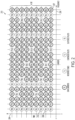
- FIG. 2 is a graphical illustration of an exemplary pilot pattern sequence 200.
- the pilot pattern sequence 200 includes a symbol group 202 of nine OFDM symbols arranged along Y axis 204 representative of time.
- the Y axis 204 can be in gradations of 200 microseconds ( ⁇ s) up to 1 millisecond. The fidelity of these gradations is dependent upon the total duration of each of the OFDM symbols.
- the graph of FIG. 2 also includes X axis 206 representative of frequency. Evenly spaced carries in each of the symbol groups are arranged along the X axis 206.
- each of the symbols within the symbol group 202 includes different carrier types comprising data carries (d i,j ), reserved tones (r i,j ), continuous pilots (c i,j ), and scattered pilots (s i,j ).
- the pilot sequence 200 is representative of a sequence configured for use in a DVB-T2 system, it can apply to any OFDM system.
- the first element in the carrier type subscript (e.g. d i,j ) represents a carrier index.
- the second element of the subscript represents a time index.
- a first OFDM symbol 207, occurring at time 0 includes a continuous pilot c 0,0 , a data carrier d 1,0 , a data carrier d 2,0 , etc.
- the data carriers are representative of actual transmitted data.
- the continuous pilots and the scattered pilots are provided to be able to perform channel estimation.
- the continuous pilots are c 0,0 and c 0,15 .
- the symbol 207 also includes a scattered pilot s 12,0 . The notion of why two different types of pilots are used is well understood by those of skill in the art and will not be discussed herein.
- OFDM systems include the concept of having pilots that are not located within any particular system.
- all of the continuous pilots have a carrier index identical to other carrier pilots, meaning they are in vertical columns with other continuous pilots.
- the fact that the continuous pilots are all vertically aligned indicates the pilot location stays the same, across different symbols. That is, if carrier 0 is a pilot in symbol 0 (i.e., symbol 207), then carrier 0 is also a pilot in a symbol 208, and a pilot in symbol 210, etc. This process is typical of DVB-T systems and wireless local area network (LAN) systems.
- LAN wireless local area network
- pilot configurations such as the configuration of FIG. 2
- the density of the continuous pilots is typically insufficient to adequately perform channel estimation.
- roving or "scattered" pilots are provided to augment the channel estimation capability of the continuous pilots.
- s 12,0 the scattered pilot is denoted as s 12,0 .
- the symbol 208 includes a scattered pilot s 9,1 etc. These are the typical types of pilots that can be found in conventional OFDM systems.
- the all of the pilot carriers are evenly spaced along the X axis 206.
- the value of these pilot carriers is derived from the output of a linear feedback shift register (LFSR). More specifically, an LFSR is used to produce a pseudorandom binary sequence (PRBS).
- PRBS pseudorandom binary sequence
- the PRBS includes a series of binary values and is used to modulate reference information ultimately transmitted in the form of continuous and scattered pilots.
- the output of the LFSR is used to determine the value(s) of the continuous and scattered pilots. This technique is used, for example, in current (DVB-T) systems discussed above.
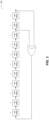
- FIG. 3 is an illustration of an exemplary LFSR 300 that can be used to produce a PRBS in accordance with the present invention.
- the LFSR 300 is a component within the pilot symbol inserter 110, illustrated in FIG. 1 .
- randomly generated sequences are not entirely random. That is, all randomly generated sequences eventually repeat themselves over time. For example, a sequence of 100110001, output from the LFSR 300, would repeat over time. If, in addition to the repeatability aspect of the PRBS, additional properties of the PRBS could be known or predicted, more clever techniques can be used to aid the receiver in performing synchronization. More clever techniques would ultimately make the synchronization process more efficient and permit simpler OFDM receiver designs.
- the autocorrelation of a typical PRBS can be computed in the binary domain. If the autocorrelation resembles an impulse function in the binary domain (i.e., suggesting that there is only one high non-zero value and the remaining values are very low non-zero values), then this particular autocorrelation computation can be used to at least determine when the sequence began within the received symbol. Knowing when the sequence began in the received symbol is useful in speeding the acquisition and synchronization process, and minimizing the occurrence of symbol ambiguities.
- a variant of the PRBS autocorrelation technique above has been used in multi-carrier systems for years, being applied, however, only in time domain.
- the present invention can be applied in OFDM based systems in frequency domain. That is, embodiments of the present invention compute the autocorrelation of the PRBS in the binary field and not on actual numbers. Time domain autocorrelation performed over real/complex numbers does not translate easily to a PRBS in the frequency domain.
- the present invention is formulated upon the concept that a "good" long PRBS in the binary domain (which is easy to find) works well after transformation to real/complex numbers via modulation.
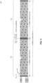
- FIG. 4 is a graphical illustration 400 of two OFDM symbols, combine to represent two symbol durations in time. More specifically, in the illustration 400, a first group of multi-carrier symbols 402 and a second group of multi-carrier symbols 404 are shown.
- the first group 402 includes symbols 0 to 9, each having a 1 st symbol duration of time 406.
- the second group of symbols 404 includes a 2 nd symbol duration time 408.
- the first group of symbols 402 can include 1704 individual carriers, such as the carriers 410, if the OFDM system operates in the 2K mode.
- the first group of symbols 402 will include 6816 carriers, however, if the 8K mode is used.
- the pseudorandom sequence used to derive the scattered and pilot carrier sequences is desirably at least twice as long as any transmitted symbol (i.e. at least two symbols duration). If at least twice as long as the transmitted symbol, symbol ambiguities can be more easily resolved. For example, if a particular sequence is only six values long, embodiments of the present invention provide the ability to determine any errors to within, for example, +/- three values.
- a Gold sequence is used. That is, to create a PRBS in accordance with the present invention, an LFSR, such as the LFSR 300, can be configured to produce a Gold sequence (with good autocorrelation properties) instead of the traditional PRBS used in conventional OFDM systems.
- a Gold sequence includes 2 m + 1 sequences each one with a period of 2 m - 1.
- This Gold sequence is desirably at least as long as the complete scattered pilot cycle that is used, or at least two symbols duration 412. In this manner, syhcnronization can be achieved completely in the time domain with only two symbols wait in the time domain. More specifically, a cross-correlation of the received data with the FFT of the modulated Gold sequence over a time period of two symbols immediately provides an identifiable peak in the output that indicates where the symbol begins.
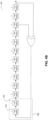
- the cost to produce this Gold sequence is simply the programming or addition of two more bits in the LFSR to generate the sequence.
- Two more bits in the LFSR can be produced by modifying the LFSR 300 of FIG. 3 .
- a modified version of the LFSR 300 is shown in FIG. 4B .
- the LFSR 302 (e.g., a modified version of the LFSR 300) can be produced by adding two more 1-bit delay blocks, such as the 1-bit delay blocks 304 and 306 of extended module 308.
- the present invention permits reusing a longer sequence, configured for use with the largest FFT size, with smaller FFT sizes, thereby decreasing the number of LFSRs that have to be created. This approach ultimately simplifies the receiver.
- Embodiments of the present invention are particularly applicable to DVB-T systems.
- Most digital television standards that are based on OFDM have multiple FFT sizes. That is, the number of carriers in one symbol could either be 2000 cariers (2K mode), or roughly 8000 (8K mode).
- the PRBS sequence in order to resolve all the ambiguities within one symbol, the PRBS sequence must be as long as the length of one symbol. Using this conventional approach, however, a different LFSR would be required for each FFT size in the receiver chip.
- the pseudorandom sequence (e.g., Gold code) is designed to be long enough such that its receiver correlation can occur over multiple symbols (i.e., twice as long as a single symbol), permitting the same sequence to be used for all the OFDM FFT sizes.
- the sequence length should be twice as long as the number of active carriers in the largest FFT size.
- the sequence length will be greater than twice the corresponding number of active carriers.
- this longer sequence does not slow down synchronization because the largest FFT size is the only one tested. The results for all smaller FFT sizes fall out as side information, thus precluding the need for testing the smaller FFT sizes.
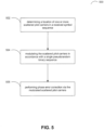
- FIG. 5 is a flowchart of an exemplary method 500 of practicing an embodiment of the present invention.
- a step 502 includes determining a location of one or more scattered pilot carriers in a received symbol sequence and modulating the scattered pilot carriers in accordance with a single pseudorandom binary sequence, as indicated in a step 504.
- phase error correction is performed via the modulated scattered pilot carriers.
- the present invention may be embodied in hardware, software, firmware, or any combination thereof.
- Embodiments of the present invention or portions thereof may be encoded in many programming languages such as hardware description languages (HDL), assembly language, C language, and netlists etc.
- HDL hardware description languages
- Verilog can be used to synthesize, simulate, and manufacture a device, e.g., a processor, application specific integrated circuit (ASIC), and/or other hardware element, that implements the aspects of one or more embodiments of the present invention.
- Verilog code can be used to model, design, verify, and/or implement a processor that can scale frames using content-aware seam carving.
- Verilog can be used to generate a register transfer level (RTL) description of logic that can be used to execute instructions so that a frame can be scaled using content-aware seam carving.
- the RTL description of the logic can then be used to generate data, e.g., graphic design system (GDS) or GDS II data, used to manufacture the desired logic or device.
- GDS graphic design system
- the Verilog code, the RTL description, and/or the GDS II data can be stored on a computer readable medium.
- the instructions executed by the logic to perform aspects of the present invention can be coded in a variety of programming languages, such as C and C++, and compiled into object code that can be executed by the logic or other device.
- aspects of the present invention can be stored, in whole or in part, on a computer readable media.
- the instructions stored on the computer readable media can adapt a processor to perform the invention, in whole or in part, or be adapted to generate a device, e.g., processor, ASIC, other hardware, that is specifically adapted to perform the invention in whole or in part.
- These instructions can also be used to ultimately configure a manufacturing process through the generation of maskworks/photomasks to generate a hardware device embodying aspects of the invention described herein.
- an HDL e g , Verilog
- Verilog code can be used to model, design, verify, and/or implement a processor that can scale frames using content-aware seam carving.
- Verilog can be used to generate a register transfer level (RTL) description of logic that can be used to execute instructions so that a frame can be scaled using content-aware seam carving
- the RTL description of the logic can then be used to generate data, e g , graphic design system (GDS) or GDS II data, used to manufacture the desired logic or device
- GDS graphic design system
- the Ve ⁇ log code, the RTL description, and/or the GDS II data can be stored on a computer readable medium
- the instructions executed by the logic to perform aspects of the present invention can be coded in a variety of programming languages, such as C and C++, and compiled into object code that can be executed by the logic or other device.
- aspects of the present invention can be stored, in whole or in part, on a computer readable media
- the instructions stored on the computer readable media can adapt a processor to perform the invention, in whole or in part, or be adapted to generate a device, e g , processor, ASIC, other hardware, that is specifically adapted to perform the invention in whole or in part
- These instructions can also be used to ultimately configure a manufacturing process through the generation of maskworks/photomasks to generate a hardware device embodying aspects of the invention described herein.
Landscapes
- Engineering & Computer Science (AREA)
- Signal Processing (AREA)
- Computer Networks & Wireless Communication (AREA)
- Synchronisation In Digital Transmission Systems (AREA)
- Mobile Radio Communication Systems (AREA)
- Radio Transmission System (AREA)
Applications Claiming Priority (3)
| Application Number | Priority Date | Filing Date | Title |
|---|---|---|---|
| US11653208P | 2008-11-20 | 2008-11-20 | |
| US12/415,727 US20100124292A1 (en) | 2008-11-20 | 2009-03-31 | Method and System for Receiver Synchronization |
| PCT/US2009/064385 WO2010059517A2 (en) | 2008-11-20 | 2009-11-13 | Method and system for receiver synchronization |
Publications (2)
| Publication Number | Publication Date |
|---|---|
| EP2359558A2 EP2359558A2 (en) | 2011-08-24 |
| EP2359558B1 true EP2359558B1 (en) | 2023-08-23 |
Family
ID=42172073
Family Applications (1)
| Application Number | Title | Priority Date | Filing Date |
|---|---|---|---|
| EP09752992.9A Active EP2359558B1 (en) | 2008-11-20 | 2009-11-13 | Method and system for receiver synchronization |
Country Status (6)
| Country | Link |
|---|---|
| US (2) | US20100124292A1 (enExample) |
| EP (1) | EP2359558B1 (enExample) |
| JP (1) | JP2012509644A (enExample) |
| KR (1) | KR101633838B1 (enExample) |
| CN (1) | CN102292951B (enExample) |
| WO (1) | WO2010059517A2 (enExample) |
Families Citing this family (13)
| Publication number | Priority date | Publication date | Assignee | Title |
|---|---|---|---|---|
| KR101615385B1 (ko) * | 2009-06-12 | 2016-04-25 | 한국전자통신연구원 | Dft sprdead ofdm 시스템을 위한 레퍼런스 심볼 구조 |
| US8837611B2 (en) * | 2011-02-09 | 2014-09-16 | Silicon Laboratories Inc. | Memory-aided synchronization in a receiver |
| KR20120099838A (ko) * | 2011-03-02 | 2012-09-12 | 삼성전자주식회사 | 방송통신시스템에서 피크 전력 대 평균 전력의 비를 감소시키기 위한 장치 및 방법 |
| US9008203B2 (en) | 2013-03-13 | 2015-04-14 | Sony Corporation | Transmitters, receivers and methods of transmitting and receiving |
| GB2511797B (en) * | 2013-03-13 | 2020-12-23 | Saturn Licensing Llc | Transmitters, receivers and methods of transmitting and receiving |
| WO2014195303A1 (en) | 2013-06-05 | 2014-12-11 | Sony Corporation | Transmitter and transmission method for transmitting payload data and emergency information |
| CN105229963B (zh) * | 2013-06-14 | 2018-11-16 | 华为技术有限公司 | 基于滤波器组的用于发射多载波信号的多载波发射器 |
| CN103501284B (zh) * | 2013-10-22 | 2016-09-28 | 湖南国科微电子股份有限公司 | 一种dvb-t2系统中精细定时同步的方法 |
| EP3078205B1 (en) * | 2013-12-06 | 2019-01-30 | Institut für Rundfunktechnik GmbH | Ofdm based broadcast communication system |
| HUE048430T2 (hu) * | 2014-12-22 | 2020-07-28 | Celwise Ab | Egy termék formázási metódusa, amely cellulóz szuszpenzió felhasználásával és az ilyen eljárásban használt szerszám vagy szerszámrész segítségével történik |
| EP3211802B1 (en) * | 2016-02-26 | 2019-01-02 | Nxp B.V. | Multi-mode transceiver arrangement |
| KR20210024253A (ko) | 2016-03-02 | 2021-03-04 | 텔레호낙티에볼라게트 엘엠 에릭슨(피유비엘) | 때때로 송신되는 미세 타이밍 기준 신호들로 동작하는 방법들 및 디바이스들 |
| CN108234376B (zh) * | 2017-12-05 | 2021-08-13 | 深圳市锐能微科技有限公司 | 无线数据通信方法及装置 |
Family Cites Families (19)
| Publication number | Priority date | Publication date | Assignee | Title |
|---|---|---|---|---|
| JP3238120B2 (ja) * | 1997-01-31 | 2001-12-10 | 株式会社次世代デジタルテレビジョン放送システム研究所 | 直交周波数分割多重信号復調装置 |
| CN1205770C (zh) * | 2001-08-29 | 2005-06-08 | 西安电子科技大学 | 一种适于数字地面广播的编码正交频分复用传输系统 |
| US7738437B2 (en) * | 2003-01-21 | 2010-06-15 | Nortel Networks Limited | Physical layer structures and initial access schemes in an unsynchronized communication network |
| EP1521413A3 (en) * | 2003-10-01 | 2009-09-30 | Panasonic Corporation | Multicarrier reception with channel estimation and equalisation |
| US8526412B2 (en) * | 2003-10-24 | 2013-09-03 | Qualcomm Incorporated | Frequency division multiplexing of multiple data streams in a wireless multi-carrier communication system |
| US7660275B2 (en) * | 2003-10-24 | 2010-02-09 | Qualcomm Incorporated | Local and wide-area transmissions in a wireless broadcast network |
| US8724447B2 (en) * | 2004-01-28 | 2014-05-13 | Qualcomm Incorporated | Timing estimation in an OFDM receiver |
| US7826343B2 (en) * | 2004-09-07 | 2010-11-02 | Qualcomm Incorporated | Position location signaling method apparatus and system utilizing orthogonal frequency division multiplexing |
| US20060227891A1 (en) * | 2005-04-07 | 2006-10-12 | Samsung Electronics Co., Ltd. | Method of channel estimation for MIMO-OFDM using phase rotated low overhead preamble |
| WO2007020710A1 (ja) * | 2005-08-19 | 2007-02-22 | Matsushita Electric Industrial Co., Ltd. | 基地局装置および移動局装置 |
| KR100723634B1 (ko) * | 2005-11-08 | 2007-06-04 | 한국전자통신연구원 | Ofdm 시스템에서 pn 수열을 이용한 프리엠블 수열생성 방법과, 시간 동기 및 주파수옵셋 추정 방법 |
| KR100721454B1 (ko) | 2005-11-10 | 2007-05-23 | 서울옵토디바이스주식회사 | 광 결정 구조체를 갖는 교류용 발광소자 및 그것을제조하는 방법 |
| CN100589468C (zh) * | 2005-12-08 | 2010-02-10 | 华为技术有限公司 | 一种对ofdm多载波信号时频调制解调的方法和装置 |
| EP2063544A1 (en) * | 2006-10-06 | 2009-05-27 | Panasonic Corporation | Wireless communication apparatus and wireless communication method |
| CN101018222B (zh) * | 2006-11-01 | 2010-12-01 | 北京创毅视讯科技有限公司 | 一种移动数字多媒体广播信号传输方法、装置及发射机与系统 |
| KR20080056423A (ko) * | 2006-12-18 | 2008-06-23 | 엘지전자 주식회사 | 셀 탐색을 위한 참조 신호의 구성 방법 |
| CN101212433B (zh) * | 2007-12-25 | 2011-12-28 | 北京创毅视讯科技有限公司 | 一种信道估计方法及信道估计装置 |
| CN101217524B (zh) * | 2007-12-26 | 2010-06-23 | 北京创毅视讯科技有限公司 | 一种信道解码装置及方法 |
| US8625686B2 (en) * | 2008-07-18 | 2014-01-07 | Advanced Micro Devices, Inc. | Window position optimization for pilot-aided OFDM system |
-
2009
- 2009-03-31 US US12/415,727 patent/US20100124292A1/en not_active Abandoned
- 2009-08-24 US US12/546,517 patent/US8265200B2/en active Active
- 2009-11-13 JP JP2011537519A patent/JP2012509644A/ja active Pending
- 2009-11-13 EP EP09752992.9A patent/EP2359558B1/en active Active
- 2009-11-13 CN CN200980155088.1A patent/CN102292951B/zh active Active
- 2009-11-13 KR KR1020117014235A patent/KR101633838B1/ko active Active
- 2009-11-13 WO PCT/US2009/064385 patent/WO2010059517A2/en not_active Ceased
Non-Patent Citations (1)
| Title |
|---|
| "Digital Video Broadcasting (DVB); Framing structure, channel coding and modulation for digital terrestrial television; ETSI EN 300 744", ETSI STANDARD, EUROPEAN TELECOMMUNICATIONS STANDARDS INSTITUTE (ETSI), SOPHIA ANTIPOLIS CEDEX, FRANCE, vol. BC, no. V1.6.1, 1 January 2009 (2009-01-01), XP014042718 * |
Also Published As
| Publication number | Publication date |
|---|---|
| KR101633838B1 (ko) | 2016-06-27 |
| US8265200B2 (en) | 2012-09-11 |
| WO2010059517A3 (en) | 2010-11-18 |
| EP2359558A2 (en) | 2011-08-24 |
| CN102292951B (zh) | 2016-01-13 |
| US20100124300A1 (en) | 2010-05-20 |
| KR20110088583A (ko) | 2011-08-03 |
| JP2012509644A (ja) | 2012-04-19 |
| CN102292951A (zh) | 2011-12-21 |
| WO2010059517A2 (en) | 2010-05-27 |
| US20100124292A1 (en) | 2010-05-20 |
Similar Documents
| Publication | Publication Date | Title |
|---|---|---|
| EP2359558B1 (en) | Method and system for receiver synchronization | |
| JP5926825B2 (ja) | 多重キャリア変調受信機におけるチャネル推定及びピーク対平均電力比低減 | |
| RU2370902C2 (ru) | Передача пилот-сигнала для системы беспроводной связи с ортогональным частотным разделением каналов | |
| TWI241810B (en) | Channel estimation in OFDM systems | |
| CN102480452B (zh) | 一种ofdm系统的载波频率同步电路及方法 | |
| JP2011523246A (ja) | Costasアレイを使用したパイロット設計 | |
| CN101741778B (zh) | 一种数据子载波上的信道估计方法 | |
| US9674024B2 (en) | Method for transmitting a signal with a preamble and corresponding devices, signal with corresponding preamble for synchronization of a receiver | |
| US7929622B2 (en) | Method of channel estimation | |
| CN101184077B (zh) | 一种多普勒频偏获取方法和装置 | |
| WO2017140651A1 (en) | Receiver circuit and methods | |
| KR20030097355A (ko) | 데이터의 영역 별 수신 우선 순위에 따라 상이한 개수의파일럿 톤을 삽입하는 디지털방송 송신기 | |
| CN110224963A (zh) | 符号定时同步位置的确定方法及装置、存储介质 | |
| CN102761505A (zh) | 频偏估计方法及装置 | |
| WO2008089595A1 (en) | Time domain interpolation method and apparatus for channel estimation | |
| CN101217290B (zh) | Tds-ofdm系统中检测前信号的捕获方法 | |
| Jung et al. | Improved Symbol Timing Detection Scheme for OFDM-Based DVB-T2 | |
| CN101257477A (zh) | 调整伪随机噪声序列并插入码元中的正交频分复用发射机 | |
| HK1120177A (en) | Ofdm transmitter capable of adjusting size of pn sequences and inserting adjusted pn sequences into ofdm symbol | |
| HK1119872A (en) | Ofdm transmitter capable of adjusting size of pn sequences and inserting adjusted pn sequences into ofdm symbol | |
| HK1119869A (en) | Ofdm transmitter capable of adjusting size of pn sequences and inserting adjusted pn sequences into ofdm symbol | |
| HK1119868A (en) | Ofdm transmitter capable of adjusting size of pn sequences and inserting adjusted pn sequences into ofdm symbol | |
| HK1118986A (en) | Ofdm transmitter capable of adjusting size of pn sequences and inserting adjusted pn sequences into ofdm symbol | |
| HK1156752A (en) | Method and apparatus for channel estimation in multiple input multiple output orthogonal frequency division multiplexing (mimo-ofdm) system | |
| KR20130046169A (ko) | 송신기 및 수신기 |
Legal Events
| Date | Code | Title | Description |
|---|---|---|---|
| PUAI | Public reference made under article 153(3) epc to a published international application that has entered the european phase |
Free format text: ORIGINAL CODE: 0009012 |
|
| 17P | Request for examination filed |
Effective date: 20110620 |
|
| AK | Designated contracting states |
Kind code of ref document: A2 Designated state(s): AT BE BG CH CY CZ DE DK EE ES FI FR GB GR HR HU IE IS IT LI LT LU LV MC MK MT NL NO PL PT RO SE SI SK SM TR |
|
| DAX | Request for extension of the european patent (deleted) | ||
| 17Q | First examination report despatched |
Effective date: 20120402 |
|
| APBK | Appeal reference recorded |
Free format text: ORIGINAL CODE: EPIDOSNREFNE |
|
| APBN | Date of receipt of notice of appeal recorded |
Free format text: ORIGINAL CODE: EPIDOSNNOA2E |
|
| APBR | Date of receipt of statement of grounds of appeal recorded |
Free format text: ORIGINAL CODE: EPIDOSNNOA3E |
|
| APAF | Appeal reference modified |
Free format text: ORIGINAL CODE: EPIDOSCREFNE |
|
| RAP1 | Party data changed (applicant data changed or rights of an application transferred) |
Owner name: ADVANCED MICRO DEVICES, INC. |
|
| RAP1 | Party data changed (applicant data changed or rights of an application transferred) |
Owner name: ADVANCED MICRO DEVICES, INC. |
|
| APBX | Invitation to file observations in appeal sent |
Free format text: ORIGINAL CODE: EPIDOSNOBA2E |
|
| APBZ | Receipt of observations in appeal recorded |
Free format text: ORIGINAL CODE: EPIDOSNOBA4E |
|
| APBT | Appeal procedure closed |
Free format text: ORIGINAL CODE: EPIDOSNNOA9E |
|
| STAA | Information on the status of an ep patent application or granted ep patent |
Free format text: STATUS: EXAMINATION IS IN PROGRESS |
|
| REG | Reference to a national code |
Ref country code: DE Ref legal event code: R079 Ref document number: 602009064966 Country of ref document: DE Free format text: PREVIOUS MAIN CLASS: H04L0027260000 Ipc: H04L0005000000 Ref country code: DE Ref legal event code: R079 Free format text: PREVIOUS MAIN CLASS: H04L0027260000 Ipc: H04L0005000000 |
|
| RIC1 | Information provided on ipc code assigned before grant |
Ipc: H04J 13/00 20060101ALN20230126BHEP Ipc: H04L 27/26 20060101ALI20230126BHEP Ipc: H04L 5/00 20060101AFI20230126BHEP |
|
| GRAP | Despatch of communication of intention to grant a patent |
Free format text: ORIGINAL CODE: EPIDOSNIGR1 |
|
| RIC1 | Information provided on ipc code assigned before grant |
Ipc: H04J 13/00 20060101ALN20230202BHEP Ipc: H04L 27/26 20060101ALI20230202BHEP Ipc: H04L 5/00 20060101AFI20230202BHEP |
|
| STAA | Information on the status of an ep patent application or granted ep patent |
Free format text: STATUS: GRANT OF PATENT IS INTENDED |
|
| INTG | Intention to grant announced |
Effective date: 20230316 |
|
| GRAS | Grant fee paid |
Free format text: ORIGINAL CODE: EPIDOSNIGR3 |
|
| GRAA | (expected) grant |
Free format text: ORIGINAL CODE: 0009210 |
|
| STAA | Information on the status of an ep patent application or granted ep patent |
Free format text: STATUS: THE PATENT HAS BEEN GRANTED |
|
| AK | Designated contracting states |
Kind code of ref document: B1 Designated state(s): AT BE BG CH CY CZ DE DK EE ES FI FR GB GR HR HU IE IS IT LI LT LU LV MC MK MT NL NO PL PT RO SE SI SK SM TR |
|
| REG | Reference to a national code |
Ref country code: GB Ref legal event code: FG4D |
|
| REG | Reference to a national code |
Ref country code: CH Ref legal event code: EP |
|
| REG | Reference to a national code |
Ref country code: IE Ref legal event code: FG4D |
|
| REG | Reference to a national code |
Ref country code: DE Ref legal event code: R096 Ref document number: 602009064966 Country of ref document: DE |
|
| REG | Reference to a national code |
Ref country code: LT Ref legal event code: MG9D |
|
| REG | Reference to a national code |
Ref country code: NL Ref legal event code: MP Effective date: 20230823 |
|
| REG | Reference to a national code |
Ref country code: AT Ref legal event code: MK05 Ref document number: 1603826 Country of ref document: AT Kind code of ref document: T Effective date: 20230823 |
|
| PG25 | Lapsed in a contracting state [announced via postgrant information from national office to epo] |
Ref country code: GR Free format text: LAPSE BECAUSE OF FAILURE TO SUBMIT A TRANSLATION OF THE DESCRIPTION OR TO PAY THE FEE WITHIN THE PRESCRIBED TIME-LIMIT Effective date: 20231124 |
|
| PG25 | Lapsed in a contracting state [announced via postgrant information from national office to epo] |
Ref country code: IS Free format text: LAPSE BECAUSE OF FAILURE TO SUBMIT A TRANSLATION OF THE DESCRIPTION OR TO PAY THE FEE WITHIN THE PRESCRIBED TIME-LIMIT Effective date: 20231223 |
|
| PG25 | Lapsed in a contracting state [announced via postgrant information from national office to epo] |
Ref country code: SE Free format text: LAPSE BECAUSE OF FAILURE TO SUBMIT A TRANSLATION OF THE DESCRIPTION OR TO PAY THE FEE WITHIN THE PRESCRIBED TIME-LIMIT Effective date: 20230823 Ref country code: PT Free format text: LAPSE BECAUSE OF FAILURE TO SUBMIT A TRANSLATION OF THE DESCRIPTION OR TO PAY THE FEE WITHIN THE PRESCRIBED TIME-LIMIT Effective date: 20231226 Ref country code: NO Free format text: LAPSE BECAUSE OF FAILURE TO SUBMIT A TRANSLATION OF THE DESCRIPTION OR TO PAY THE FEE WITHIN THE PRESCRIBED TIME-LIMIT Effective date: 20231123 Ref country code: NL Free format text: LAPSE BECAUSE OF FAILURE TO SUBMIT A TRANSLATION OF THE DESCRIPTION OR TO PAY THE FEE WITHIN THE PRESCRIBED TIME-LIMIT Effective date: 20230823 Ref country code: LV Free format text: LAPSE BECAUSE OF FAILURE TO SUBMIT A TRANSLATION OF THE DESCRIPTION OR TO PAY THE FEE WITHIN THE PRESCRIBED TIME-LIMIT Effective date: 20230823 Ref country code: LT Free format text: LAPSE BECAUSE OF FAILURE TO SUBMIT A TRANSLATION OF THE DESCRIPTION OR TO PAY THE FEE WITHIN THE PRESCRIBED TIME-LIMIT Effective date: 20230823 Ref country code: IS Free format text: LAPSE BECAUSE OF FAILURE TO SUBMIT A TRANSLATION OF THE DESCRIPTION OR TO PAY THE FEE WITHIN THE PRESCRIBED TIME-LIMIT Effective date: 20231223 Ref country code: HR Free format text: LAPSE BECAUSE OF FAILURE TO SUBMIT A TRANSLATION OF THE DESCRIPTION OR TO PAY THE FEE WITHIN THE PRESCRIBED TIME-LIMIT Effective date: 20230823 Ref country code: GR Free format text: LAPSE BECAUSE OF FAILURE TO SUBMIT A TRANSLATION OF THE DESCRIPTION OR TO PAY THE FEE WITHIN THE PRESCRIBED TIME-LIMIT Effective date: 20231124 Ref country code: FI Free format text: LAPSE BECAUSE OF FAILURE TO SUBMIT A TRANSLATION OF THE DESCRIPTION OR TO PAY THE FEE WITHIN THE PRESCRIBED TIME-LIMIT Effective date: 20230823 Ref country code: AT Free format text: LAPSE BECAUSE OF FAILURE TO SUBMIT A TRANSLATION OF THE DESCRIPTION OR TO PAY THE FEE WITHIN THE PRESCRIBED TIME-LIMIT Effective date: 20230823 |
|
| PG25 | Lapsed in a contracting state [announced via postgrant information from national office to epo] |
Ref country code: PL Free format text: LAPSE BECAUSE OF FAILURE TO SUBMIT A TRANSLATION OF THE DESCRIPTION OR TO PAY THE FEE WITHIN THE PRESCRIBED TIME-LIMIT Effective date: 20230823 |
|
| PG25 | Lapsed in a contracting state [announced via postgrant information from national office to epo] |
Ref country code: ES Free format text: LAPSE BECAUSE OF FAILURE TO SUBMIT A TRANSLATION OF THE DESCRIPTION OR TO PAY THE FEE WITHIN THE PRESCRIBED TIME-LIMIT Effective date: 20230823 |
|
| PG25 | Lapsed in a contracting state [announced via postgrant information from national office to epo] |
Ref country code: SM Free format text: LAPSE BECAUSE OF FAILURE TO SUBMIT A TRANSLATION OF THE DESCRIPTION OR TO PAY THE FEE WITHIN THE PRESCRIBED TIME-LIMIT Effective date: 20230823 Ref country code: RO Free format text: LAPSE BECAUSE OF FAILURE TO SUBMIT A TRANSLATION OF THE DESCRIPTION OR TO PAY THE FEE WITHIN THE PRESCRIBED TIME-LIMIT Effective date: 20230823 Ref country code: ES Free format text: LAPSE BECAUSE OF FAILURE TO SUBMIT A TRANSLATION OF THE DESCRIPTION OR TO PAY THE FEE WITHIN THE PRESCRIBED TIME-LIMIT Effective date: 20230823 Ref country code: EE Free format text: LAPSE BECAUSE OF FAILURE TO SUBMIT A TRANSLATION OF THE DESCRIPTION OR TO PAY THE FEE WITHIN THE PRESCRIBED TIME-LIMIT Effective date: 20230823 Ref country code: DK Free format text: LAPSE BECAUSE OF FAILURE TO SUBMIT A TRANSLATION OF THE DESCRIPTION OR TO PAY THE FEE WITHIN THE PRESCRIBED TIME-LIMIT Effective date: 20230823 Ref country code: CZ Free format text: LAPSE BECAUSE OF FAILURE TO SUBMIT A TRANSLATION OF THE DESCRIPTION OR TO PAY THE FEE WITHIN THE PRESCRIBED TIME-LIMIT Effective date: 20230823 Ref country code: SK Free format text: LAPSE BECAUSE OF FAILURE TO SUBMIT A TRANSLATION OF THE DESCRIPTION OR TO PAY THE FEE WITHIN THE PRESCRIBED TIME-LIMIT Effective date: 20230823 |
|
| REG | Reference to a national code |
Ref country code: DE Ref legal event code: R097 Ref document number: 602009064966 Country of ref document: DE |
|
| PG25 | Lapsed in a contracting state [announced via postgrant information from national office to epo] |
Ref country code: IT Free format text: LAPSE BECAUSE OF FAILURE TO SUBMIT A TRANSLATION OF THE DESCRIPTION OR TO PAY THE FEE WITHIN THE PRESCRIBED TIME-LIMIT Effective date: 20230823 |
|
| P01 | Opt-out of the competence of the unified patent court (upc) registered |
Effective date: 20240517 |
|
| PLBE | No opposition filed within time limit |
Free format text: ORIGINAL CODE: 0009261 |
|
| STAA | Information on the status of an ep patent application or granted ep patent |
Free format text: STATUS: NO OPPOSITION FILED WITHIN TIME LIMIT |
|
| REG | Reference to a national code |
Ref country code: CH Ref legal event code: PL |
|
| PG25 | Lapsed in a contracting state [announced via postgrant information from national office to epo] |
Ref country code: MC Free format text: LAPSE BECAUSE OF FAILURE TO SUBMIT A TRANSLATION OF THE DESCRIPTION OR TO PAY THE FEE WITHIN THE PRESCRIBED TIME-LIMIT Effective date: 20230823 |
|
| PG25 | Lapsed in a contracting state [announced via postgrant information from national office to epo] |
Ref country code: LU Free format text: LAPSE BECAUSE OF NON-PAYMENT OF DUE FEES Effective date: 20231113 |
|
| PG25 | Lapsed in a contracting state [announced via postgrant information from national office to epo] |
Ref country code: CH Free format text: LAPSE BECAUSE OF NON-PAYMENT OF DUE FEES Effective date: 20231130 |
|
| 26N | No opposition filed |
Effective date: 20240524 |
|
| PG25 | Lapsed in a contracting state [announced via postgrant information from national office to epo] |
Ref country code: MC Free format text: LAPSE BECAUSE OF FAILURE TO SUBMIT A TRANSLATION OF THE DESCRIPTION OR TO PAY THE FEE WITHIN THE PRESCRIBED TIME-LIMIT Effective date: 20230823 Ref country code: LU Free format text: LAPSE BECAUSE OF NON-PAYMENT OF DUE FEES Effective date: 20231113 Ref country code: CH Free format text: LAPSE BECAUSE OF NON-PAYMENT OF DUE FEES Effective date: 20231130 Ref country code: SI Free format text: LAPSE BECAUSE OF FAILURE TO SUBMIT A TRANSLATION OF THE DESCRIPTION OR TO PAY THE FEE WITHIN THE PRESCRIBED TIME-LIMIT Effective date: 20230823 |
|
| REG | Reference to a national code |
Ref country code: BE Ref legal event code: MM Effective date: 20231130 |
|
| REG | Reference to a national code |
Ref country code: IE Ref legal event code: MM4A |
|
| PG25 | Lapsed in a contracting state [announced via postgrant information from national office to epo] |
Ref country code: IE Free format text: LAPSE BECAUSE OF NON-PAYMENT OF DUE FEES Effective date: 20231113 |
|
| PG25 | Lapsed in a contracting state [announced via postgrant information from national office to epo] |
Ref country code: BE Free format text: LAPSE BECAUSE OF NON-PAYMENT OF DUE FEES Effective date: 20231130 |
|
| PG25 | Lapsed in a contracting state [announced via postgrant information from national office to epo] |
Ref country code: FR Free format text: LAPSE BECAUSE OF NON-PAYMENT OF DUE FEES Effective date: 20231130 |
|
| PG25 | Lapsed in a contracting state [announced via postgrant information from national office to epo] |
Ref country code: IE Free format text: LAPSE BECAUSE OF NON-PAYMENT OF DUE FEES Effective date: 20231113 Ref country code: FR Free format text: LAPSE BECAUSE OF NON-PAYMENT OF DUE FEES Effective date: 20231130 Ref country code: BE Free format text: LAPSE BECAUSE OF NON-PAYMENT OF DUE FEES Effective date: 20231130 |
|
| PG25 | Lapsed in a contracting state [announced via postgrant information from national office to epo] |
Ref country code: BG Free format text: LAPSE BECAUSE OF FAILURE TO SUBMIT A TRANSLATION OF THE DESCRIPTION OR TO PAY THE FEE WITHIN THE PRESCRIBED TIME-LIMIT Effective date: 20230823 |
|
| PG25 | Lapsed in a contracting state [announced via postgrant information from national office to epo] |
Ref country code: BG Free format text: LAPSE BECAUSE OF FAILURE TO SUBMIT A TRANSLATION OF THE DESCRIPTION OR TO PAY THE FEE WITHIN THE PRESCRIBED TIME-LIMIT Effective date: 20230823 |
|
| PG25 | Lapsed in a contracting state [announced via postgrant information from national office to epo] |
Ref country code: HU Free format text: LAPSE BECAUSE OF FAILURE TO SUBMIT A TRANSLATION OF THE DESCRIPTION OR TO PAY THE FEE WITHIN THE PRESCRIBED TIME-LIMIT; INVALID AB INITIO Effective date: 20091113 |
|
| PG25 | Lapsed in a contracting state [announced via postgrant information from national office to epo] |
Ref country code: CY Free format text: LAPSE BECAUSE OF FAILURE TO SUBMIT A TRANSLATION OF THE DESCRIPTION OR TO PAY THE FEE WITHIN THE PRESCRIBED TIME-LIMIT; INVALID AB INITIO Effective date: 20091113 |
|
| PG25 | Lapsed in a contracting state [announced via postgrant information from national office to epo] |
Ref country code: TR Free format text: LAPSE BECAUSE OF FAILURE TO SUBMIT A TRANSLATION OF THE DESCRIPTION OR TO PAY THE FEE WITHIN THE PRESCRIBED TIME-LIMIT Effective date: 20230823 |
|
| PGFP | Annual fee paid to national office [announced via postgrant information from national office to epo] |
Ref country code: DE Payment date: 20251010 Year of fee payment: 17 |
|
| PGFP | Annual fee paid to national office [announced via postgrant information from national office to epo] |
Ref country code: GB Payment date: 20251105 Year of fee payment: 17 |