EP2359098B1 - Convertisseur de mesure de pression différentielle - Google Patents
Convertisseur de mesure de pression différentielle Download PDFInfo
- Publication number
- EP2359098B1 EP2359098B1 EP09765062.6A EP09765062A EP2359098B1 EP 2359098 B1 EP2359098 B1 EP 2359098B1 EP 09765062 A EP09765062 A EP 09765062A EP 2359098 B1 EP2359098 B1 EP 2359098B1
- Authority
- EP
- European Patent Office
- Prior art keywords
- differential pressure
- sensor
- housing
- process connection
- pressure sensor
- Prior art date
- Legal status (The legal status is an assumption and is not a legal conclusion. Google has not performed a legal analysis and makes no representation as to the accuracy of the status listed.)
- Active
Links
- 238000000034 method Methods 0.000 claims description 67
- 238000007789 sealing Methods 0.000 claims description 37
- 238000011156 evaluation Methods 0.000 claims description 21
- 239000012530 fluid Substances 0.000 description 7
- 230000000295 complement effect Effects 0.000 description 4
- 238000011161 development Methods 0.000 description 4
- 238000010276 construction Methods 0.000 description 3
- 239000004065 semiconductor Substances 0.000 description 3
- 238000013461 design Methods 0.000 description 2
- 238000003780 insertion Methods 0.000 description 2
- 230000037431 insertion Effects 0.000 description 2
- 239000000463 material Substances 0.000 description 2
- 238000005259 measurement Methods 0.000 description 2
- 238000012545 processing Methods 0.000 description 2
- 239000007787 solid Substances 0.000 description 2
- 125000006850 spacer group Chemical group 0.000 description 2
- 230000006978 adaptation Effects 0.000 description 1
- 229920001971 elastomer Polymers 0.000 description 1
- 239000000806 elastomer Substances 0.000 description 1
- 238000005516 engineering process Methods 0.000 description 1
- 230000010354 integration Effects 0.000 description 1
- 238000004519 manufacturing process Methods 0.000 description 1
- 239000012528 membrane Substances 0.000 description 1
- 238000000926 separation method Methods 0.000 description 1
Images

Classifications
-
- G—PHYSICS
- G01—MEASURING; TESTING
- G01L—MEASURING FORCE, STRESS, TORQUE, WORK, MECHANICAL POWER, MECHANICAL EFFICIENCY, OR FLUID PRESSURE
- G01L19/00—Details of, or accessories for, apparatus for measuring steady or quasi-steady pressure of a fluent medium insofar as such details or accessories are not special to particular types of pressure gauges
- G01L19/14—Housings
Definitions
- the invention relates to a differential pressure transmitter.
- Generic differential pressure transducers for detecting a pressure difference between a first fluid pressure and a second fluid pressure typically include a sensor assembly and an evaluation assembly, wherein the sensor assembly comprises a differential pressure sensor, a first process interface flange, and a second process interface flange, wherein the differential pressure sensor is axially clamped between the first process connection flange and the second process connection flange, wherein the sensor assembly is mountable by means of the process connection flanges to a process plant, wherein the differential pressure sensor can be acted upon by a first media pressure via the first process connection flange and with a second media pressure via the second process connection flange, the differential pressure sensor having a signal output for outputting a signal representing a measured difference between the first fluid pressure and the second fluid pressure, wherein the evaluation module has a housing and an electronic evaluation circuit in the housing, wherein the evaluation circuit has a signal input, wherein the housing has an input opening through which the signal output of the differential pressure sensor is connected to the signal input of the evaluation circuit, and where
- the housing of the evaluation module with a housing neck, in which the input opening is arranged, usually screwed onto a connecting thread, which protrudes from the lateral surface of a cylindrical differential pressure sensor.
- a connecting thread which protrudes from the lateral surface of a cylindrical differential pressure sensor.
- Corresponding differential pressure transmitters are manufactured and marketed, for example, by the Applicant under the name Deltabar or by Rosemount under the designation 1151. Further embodiments of this principle are, for example, in EP 0 843 810 B1 and in the International Patent Application WO 96/06338 disclosed.
- the publication DE 103 47 861 A1 discloses a differential pressure transducer with a differential pressure sensor clamped in shunt with a surrounding cylindrical tube between two process connection flanges.
- the cylindrical tube carries on its outer surface an electronics housing.
- connection thread onto which the housing neck of the housing of the evaluation module is screwed, must be led out of the space between the process connection flanges completely, so that a sufficiently strongly dimensioned screw connection between the housing and the sensor assembly does not interfere with the Bottles interfere.
- the differential pressure transducer includes a differential pressure sensor, a first process interface flange, and a second process interface flange, the differential pressure sensor being clamped between the first process interface flange and the second process interface flange and first and second seals, the differential pressure sensor having a first media pressure via the first process interface flange and the second Process connection flange can be acted upon by a second media pressure; a housing containing an electronic evaluation circuit, the housing having an input port through which the differential pressure sensor is connected to the evaluation circuit, and wherein the housing has at least one extension which extends between the first and the second process connection flange, wherein the extension in shunt to the differential pressure sensor is clamped between the flanges, so that the housing is held by the clamped extension, according to the invention the differential pressure sensor has a sensor neck, the sensor neck extending from an outer surface of the differential pressure sensor into the inlet opening of the housing, an annular gap being formed between the sensor neck and the inlet opening of the housing, wherein the signal output of
- the extension comprises a frame which encloses the differential pressure sensor.
- the frame is clamped between the process connection flanges, at least on one side, preferably on both sides, along a closed sealing surface, which may comprise a sealing ring, in particular an elastomer sealing ring.
- the construction according to the invention allows a comparatively compact and cost-effective construction, since no sufficiently strong dimensioned thread for supporting the housing on the lateral surface of a differential pressure sensor must be arranged to ensure a screw connection between the housing and the sensor assembly.
- the extension or the frame may be made of the housing material, which is usually less expensive than the materials of the mechanical components of the sensor assembly.
- the contact pressure on the seals between the differential pressure sensor and the process connection flanges is greater than the contact pressure on the Sealing surfaces between the frame and the process connection surfaces acts.
- the force on the seals between the differential pressure sensor and the process connection flanges may be greater than the force acting on the sealing surfaces between the frame and the process pads.
- the differential pressure sensor and the extension by means of a plurality of bolts, in particular two, three or four bolts, clamped between the process connection flanges, wherein the axes of the bolts extend substantially perpendicular to the sealing surfaces, and wherein bolts in a presently preferred embodiment of Invention are enclosed by an outer contour of the frame.
- differential pressure transmitter further comprises a substantially axially symmetrical, in particular at least partially cylindrical guide sleeve which is arranged in an annular gap which is formed between the inlet opening of the housing and a sensor neck of the differential pressure sensor, wherein the sensor neck of a lateral surface of the Differential pressure sensor extends into the input port, and wherein the signal output of the differential pressure sensor passes through the sensor neck.
- the guide sleeve serves in particular to align the axis of the sensor neck with respect to the inlet opening of the housing.
- the sleeve thus supports the extremely compact design of the differential pressure transmitter.
- This is to be understood as follows.
- a frame is provided on the housing to provide sufficient stability to the housing on the sensor assembly.
- a (less massive and possibly shorter) sensor neck is mechanically coupled to the housing in such a way that the axis of the sensor neck with respect to the inlet opening of the housing is aligned to bring the differential pressure sensor with respect to the housing and the frame in a defined position.
- the clear height of the frame would have to be at least as large as the maximum height of the differential pressure sensor in the direction of the axis of the sensor neck.
- the differential pressure sensor can be very well tilted when inserted into the frame.
- the clear height of the frame can be significantly reduced.
- the sleeve therefore preferably comprises a first sleeve sealing surface and the housing has an inlet sealing surface surrounding the inlet opening, whereby a first opening between the sleeve and the housing is sealed relative to the latter by means of the inlet sealing surface and the first sleeve sealing surface and optionally a sealing ring disposed therebetween.
- the sleeve further comprises a second sleeve sealing surface and the sensor neck an annular sensor neck sealing surface, wherein a second opening between the sleeve and the sensor neck is sealed by means of the sensor neck sealing surface and the second sleeve sealing surface and optionally a sealing ring therebetween.
- the seals of the first opening and the second opening are designed in a development of the invention so that they survive the failure of a process seal at least for a defined period of time, for example, is required to reduce a due to the failure of the process seal at the seals pending overpressure.
- a bore which may optionally contain a filter, be provided through the frame, and / or at least one of the seals between the frame and the process connection flanges can be dimensioned so weak that they occur when an overpressure after failure a process seal fails immediately and thus enables the pressure reduction.
- the first opening and / or the second opening may in particular comprise an annular gap, the annular gap in particular between smooth, cylindrical lateral surfaces or lateral surfaces can run with impressed threads.
- the first opening and the second opening respectively meet the requirement for a flame arrester in particular.
- this requires, given a given length of the gap, that a critical, maximum distance of the lateral surfaces bounding the gap must not be exceeded.
- this applies accordingly.
- the sleeve has an outer circumferential surface with a thread, which engages in a complementary internal thread in the wall surrounding the input opening of the housing.
- the inner circumferential surface of the sleeve is substantially smooth in this embodiment. Both lateral surfaces of the sleeve meet with their respective opposite surfaces flame arresters especially after the ignition protection Ex-d.
- the sensor assembly comprises a positioning body, which defines the position of the differential pressure sensor in the frame.
- the positioning body for example, at least partially surround the lateral surface of the differential pressure sensor and align the differential pressure sensor in addition to the sleeve with respect to the frame.
- the positioning body in particular, may be a plastic body, which in particular is so flexible that it does not preclude an adaptation of the position of the pressure measuring cell under the clamping forces on the part of the process connection flanges.
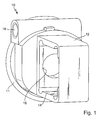
- the in Fig. 1 Housing body 10 shown includes a housing 11, which apart from functionally deviations has a substantially rotationally symmetrical structure about a housing longitudinal axis.
- a frame 12 which encloses a substantially rectangular sensor receptacle 14.
- the plane-parallel end faces of the frame 12 extend substantially parallel to the housing longitudinal axis.
- an inlet opening 16 is arranged, whose axis is aligned with the housing longitudinal axis. In this inlet opening, the neck of a differential pressure sensor is to be positioned.
- Fig. 1 further shows a signal output port 18 through which signal and supply lines are guided in the housing 11 during measurement operation.
- Fig. 2 shows a partially mounted differential pressure transducer 1, with the basis of Fig. 1 explained housing body 10, in the sensor receptacle 14, a differential pressure sensor 20 is inserted.
- the differential pressure sensor 20 comprises a substantially cylindrical sensor body 22 whose axis is perpendicular to the axis of the housing longitudinal axis and to the end faces of the frame 12. runs. The two end faces of the sensor body 22 are to be acted upon in measuring operation with a first and second pressure, wherein the differential pressure sensor provides a primary signal which corresponds to the difference between the first and the second pressure.
- the differential pressure sensor 20 has a substantially cylindrical sensor neck 24, extend through the electrical feedthroughs, wherein the longitudinal axis of the sensor neck 24 is aligned with the housing longitudinal axis, and wherein the sensor neck 24 in the entrance opening 16 of the housing 11 extends.
- the spacers 32 are here designed annular, which gives them a certain flexibility.
- a process connection flange 50 is shown, which abuts against the rear end face of the frame 12 in order to apply a first medium pressure to the rear end face of the sensor body 22.
- the process connection flange has a channel which extends from an opening 54 in a process connection surface visible in the drawing through the process connection flange to an opening which lies approximately on the axis of the sensor body 22.
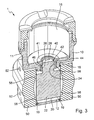
- Fig. 3 shows a longitudinal section along the housing longitudinal axis, wherein the clamped between the two process connection flanges 50 sensor body 22 of the differential pressure sensor 20 in the lower part of Fig. 3 can be seen.
- the flanges each have an annular circumferential recess 56, which receives in each case an elastic O-ring, not shown here, the pressure-tight against the adjacent end face of the sensor body 22 is tensioned.
- an elastic tensioning cord is arranged, which is also stretched by the process connection flanges 50, whereby the frame 12 - and with it the entire housing body 10 - held with respect to the flanges and also clamped differential pressure sensor 20 in position becomes.
- the housing 11 contains in its interior a housing chamber 15, in which an evaluation circuit, not shown here, is arranged.
- a sleeve 40 is provided which slid according to an embodiment on the sensor neck and by means of an external thread its lateral surface is screwed with a complementary internal thread in the wall of the inlet opening 16.
- an annular gap is formed, which meets the requirements for a flame arrester of type of protection ex-d.
- the thread pairing can also meet the requirements for a flame arrester of type of protection ex-d.
- the sleeve 40 further has an annular disk-shaped end face 41, which extends radially inwardly from the inner wall 46 on the one hand to form a first sleeve sealing surface 42, against which a first sealing ring is clamped between the first sleeve sealing surface 42 and a complementary sealing surface on the sensor neck on the other hand, wherein the end face 41 on the other hand extends radially outwardly from the shell surface of the sleeve 40 to form a second sleeve sealing surface 44 against which a second sealing ring bears, between the first sleeve sealing surface 44 and a complementary sealing surface at the edge or near the inlet opening 16 of the housing body 10 is clamped.
- a second containment is realized, which prevents the process medium can get into the housing chamber 15 after a failure of a process seal.
- a pressure relief valve or a rupture disc can be arranged in the frame 12, a pressure relief valve or a rupture disc, which are dimensioned so that they allow a pressure reduction in the sensor receptacle 14 before the seals to the housing chamber 15 fail.
- the electrical connections for the differential pressure sensor are arranged, via which this is connected to the evaluation circuit, not shown here in the housing chamber.
- the differential pressure sensor 20 is in Fig. 3 for the sake of clarity on average as a solid block shown. Of course, this does not correspond to the actual circumstances.
- the sensor body 22 includes a the skilled worker, not shown here measuring unit with a semiconductor differential pressure transducer, as for example in EP 1299701 B1 is described, wherein the measuring mechanism at the end faces of the sensor body each having a metallic separation membrane which closes a hydraulic path which extends from the respective end face to a side of a measuring diaphragm of the semiconductor differential pressure transducer.
- a capacitive differential pressure sensor may be provided in the sensor neck, for example, an electronic circuit for processing the signals of the semiconductor differential pressure transducer is provided. Since in the context of the present invention, which essentially relates to the constructive integration of a differential pressure sensor in the housing of a differential pressure transducer, does not depend on the details of the sensors and the signal processing, these simplifications of the presentation are justified.
Landscapes
- Physics & Mathematics (AREA)
- General Physics & Mathematics (AREA)
- Measuring Fluid Pressure (AREA)
Claims (8)
- Transmetteur de pression différentielle, comprenant :un capteur de pression différentielle (20), qui présente une sortie signal afin d'émettre un signal dépendant d'une différence mesurée entre une première pression de produit et une deuxième pression de produit, ou qui représente cette différence,une première bride de raccordement au process (50) et une deuxième bride de raccordement au process (50),le capteur de pression différentielle (20) étant fixé entre la première bride de raccordement au process (50) et la deuxième bride de raccordement au process (50) et un premier et un deuxième joint, les joints étant disposés respectivement entre les brides de raccordement au process et le capteur de pression différentielle,le capteur de pression différentielle pouvant être alimenté, par l'intermédiaire de la première bride de raccordement au process, avec la première pression de produit et, par l'intermédiaire de la deuxième bride de raccordement au process, avec la deuxième pression de produit ;un boîtier (11), lequel contient un circuit d'exploitation électronique, le boîtier (11) présentant une ouverture d'entrée (16), à travers laquelle la sortie signal du capteur de pression différentielle est raccordée à une entrée signal du circuit d'exploitation, et le boîtier (11) présentant au minimum un prolongement (12), qui s'étend entre la première et la deuxième bride de raccordement au process (50), le prolongement étant fixé dans la dérivation relative au capteur de pression différentielle (20) entre les brides (50), de telle sorte que le boîtier est maintenu par le prolongement fixé,caractérisé en ce quele capteur de pression différentielle présente un col de capteur, ce dernier s'étendant depuis une surface latérale du capteur de pression différentielle jusque dans l'ouverture d'entrée du boîtier, une fente annulaire étant formée entre le col de capteur et l'ouverture d'entrée du boîtier,le transmetteur de pression différentielle présentant en outre une douille de guidage, laquelle est disposée dans la fente annulaire.
- Transmetteur de pression différentielle selon la revendication 1, pour lequel le prolongement présente un cadre (12), lequel entoure le capteur de pression différentielle.
- Transmetteur de pression différentielle selon la revendication 2, pour lequel le cadre est fixé au moins d'un côté, de préférence des deux côtés, le long d'une surface d'étanchéité (19) fermée en soi, entre les brides de raccordement au process (50).
- Transmetteur de pression différentielle selon la revendication 2 ou 3, pour lequel le contour extérieur du cadre affleure, dans les plans des surfaces d'étanchéité, le contour extérieur des brides de raccordement au process.
- Transmetteur de pression différentielle selon la revendication 2, 3 ou 4, pour lequel le capteur de pression différentielle et le prolongement sont fixés au moyen de plusieurs boulons entre les brides de raccordement au process.
- Transmetteur de pression différentielle selon la revendication 5, pour lequel les boulons sont entourés par un contour extérieur du cadre.
- Transmetteur de pression différentielle selon l'une des revendications 1 à 6, pour lequel la douille comprend une première surface d'étanchéité de douille et pour lequel le boîtier comprend une surface d'étanchéité d'entrée entourant l'ouverture d'entrée, une première ouverture entre la douille et le boîtier étant rendue étanche au moyen de la surface d'étanchéité d'entrée et de la première surface d'étanchéité de douille, ainsi qu'avec une éventuelle bague d'étanchéité disposée entre les deux.
- Transmetteur de pression différentielle selon la revendication 7, pour lequel la douille comprend une deuxième surface d'étanchéité de douille et pour lequel le col de capteur comprend une surface d'étanchéité de col de capteur annulaire, une deuxième ouverture entre la douille et le col de capteur étant rendue étanche au moyen de la surface d'étanchéité de col de capteur et de la deuxième surface d'étanchéité de douille, ainsi qu'avec une éventuelle bague d'étanchéité disposée entre les deux.
Applications Claiming Priority (2)
| Application Number | Priority Date | Filing Date | Title |
|---|---|---|---|
| DE102008054991A DE102008054991A1 (de) | 2008-12-19 | 2008-12-19 | Differenzdruckmessumformer |
| PCT/EP2009/065599 WO2010069710A1 (fr) | 2008-12-19 | 2009-11-23 | Convertisseur de mesure de pression différentielle |
Publications (2)
| Publication Number | Publication Date |
|---|---|
| EP2359098A1 EP2359098A1 (fr) | 2011-08-24 |
| EP2359098B1 true EP2359098B1 (fr) | 2013-06-26 |
Family
ID=41630920
Family Applications (1)
| Application Number | Title | Priority Date | Filing Date |
|---|---|---|---|
| EP09765062.6A Active EP2359098B1 (fr) | 2008-12-19 | 2009-11-23 | Convertisseur de mesure de pression différentielle |
Country Status (5)
| Country | Link |
|---|---|
| US (1) | US8726735B2 (fr) |
| EP (1) | EP2359098B1 (fr) |
| CN (1) | CN102257363B (fr) |
| DE (1) | DE102008054991A1 (fr) |
| WO (1) | WO2010069710A1 (fr) |
Families Citing this family (7)
| Publication number | Priority date | Publication date | Assignee | Title |
|---|---|---|---|---|
| DE102010031679A1 (de) * | 2010-07-22 | 2012-01-26 | Robert Bosch Gmbh | Drucksensor sowie Verfahren zum Herstellen eines Drucksensors |
| DE102010041169A1 (de) * | 2010-09-22 | 2012-03-22 | Robert Bosch Gmbh | Drucksensor, insbesondere für Bremsvorrichtung |
| DE102011088303A1 (de) * | 2011-12-12 | 2013-06-13 | Endress + Hauser Gmbh + Co. Kg | Tubusflanschdruckmittler, Druckmessanordnung mit einem solchen Tubusflanschdruckmittler und Druckmessstelle mit einer solchen Druckmessanordnung |
| DE102013106601A1 (de) | 2013-06-25 | 2015-01-08 | Endress + Hauser Gmbh + Co. Kg | Druckmessgerät, insbesondere Differenzdruckmessgerät |
| DE102014115515B3 (de) * | 2014-10-24 | 2016-03-24 | Endress + Hauser Gmbh + Co. Kg | Vorrichtung zur Durchführung einer Dichtheitsprüfung eines Differenzdruckmessaufnehmers |
| DE102017119358A1 (de) * | 2017-08-24 | 2019-02-28 | Endress+Hauser SE+Co. KG | Modulares Feldgerät |
| DE102018129497B4 (de) * | 2018-11-22 | 2022-01-13 | Balluff Gmbh | Sensorgehäuse und Sensor |
Family Cites Families (25)
| Publication number | Priority date | Publication date | Assignee | Title |
|---|---|---|---|---|
| US4172388A (en) * | 1978-03-09 | 1979-10-30 | American Chain & Cable Company, Inc. | Differential pressure sensor with dual level overrange protection |
| US4527428A (en) * | 1982-12-30 | 1985-07-09 | Hitachi, Ltd. | Semiconductor pressure transducer |
| IT1164315B (it) * | 1983-07-08 | 1987-04-08 | Kent Tieghi Spa | Trasmettitore di pressioni differenziali di fluidi di processo industriali, con compensazione degli effetti delle variazioni di pressione statica |
| US4713969A (en) * | 1983-09-30 | 1987-12-22 | Kabushiki Kaisha Toshiba | Differential pressure transmission apparatus |
| DE8407659U1 (de) * | 1984-03-09 | 1985-03-14 | Siemens AG, 1000 Berlin und 8000 München | Druck- oder druckdifferenzmessgeraet |
| DE3443419A1 (de) * | 1984-11-26 | 1986-05-28 | Siemens AG, 1000 Berlin und 8000 München | Druckdifferenz-messgeraet mit einem halbleiter-drucksensor |
| JPH0348128A (ja) * | 1989-07-17 | 1991-03-01 | Yamatake Honeywell Co Ltd | 差圧・圧力発信器 |
| US5583294A (en) | 1994-08-22 | 1996-12-10 | The Foxboro Company | Differential pressure transmitter having an integral flame arresting body and overrange diaphragm |
| US5656782A (en) * | 1994-12-06 | 1997-08-12 | The Foxboro Company | Pressure sealed housing apparatus and methods |
| EP0723143B1 (fr) * | 1995-01-12 | 1998-05-13 | Endress + Hauser Gmbh + Co. | Capteur de pression céramique avec une pièce de connection pour un récipient et une garniture double |
| US5596147A (en) * | 1995-11-17 | 1997-01-21 | Wilda; Douglas W. | Coplanar pressure sensor mounting for remote sensor |
| US5668322A (en) | 1996-06-13 | 1997-09-16 | Rosemount Inc. | Apparatus for coupling a transmitter to process fluid having a sensor extension selectively positionable at a plurality of angles |
| EP0984248B1 (fr) * | 1998-09-02 | 2004-06-09 | Endress + Hauser GmbH + Co. KG | Capteur de mesure |
| US6484107B1 (en) * | 1999-09-28 | 2002-11-19 | Rosemount Inc. | Selectable on-off logic modes for a sensor module |
| CN1151366C (zh) * | 1999-09-28 | 2004-05-26 | 罗斯蒙德公司 | 环境密封仪器环路适配器 |
| US6510740B1 (en) | 1999-09-28 | 2003-01-28 | Rosemount Inc. | Thermal management in a pressure transmitter |
| EP1172640A1 (fr) | 2000-07-13 | 2002-01-16 | Endress + Hauser GmbH + Co. | Capteur de pression différentielle |
| JP4757373B2 (ja) * | 2000-07-24 | 2011-08-24 | エルピーダメモリ株式会社 | 半導体記憶装置及びそのメモリセルアクセス方法 |
| JP4040971B2 (ja) * | 2002-12-27 | 2008-01-30 | 株式会社山武 | 差圧・圧力発信器 |
| US6918303B2 (en) * | 2003-08-12 | 2005-07-19 | Invensys | Bi-planar differential pressure transmitter with orthogonal process connections |
| DE10347861A1 (de) | 2003-10-10 | 2005-04-28 | Endress & Hauser Gmbh & Co Kg | Meßaufnehmer |
| JP2005257498A (ja) * | 2004-03-12 | 2005-09-22 | Denso Corp | 圧力センサ |
| US7363811B2 (en) * | 2005-04-07 | 2008-04-29 | Endress + Hauser Flowtec Ag | Measurement pickup |
| US7401522B2 (en) * | 2005-05-26 | 2008-07-22 | Rosemount Inc. | Pressure sensor using compressible sensor body |
| DE102006047474B4 (de) * | 2006-10-05 | 2013-12-05 | Endress + Hauser Gmbh + Co. Kg | Druckmessgerät für die Prozessmesstechnik |
-
2008
- 2008-12-19 DE DE102008054991A patent/DE102008054991A1/de not_active Withdrawn
-
2009
- 2009-11-23 US US13/140,187 patent/US8726735B2/en active Active
- 2009-11-23 EP EP09765062.6A patent/EP2359098B1/fr active Active
- 2009-11-23 CN CN200980151471.XA patent/CN102257363B/zh active Active
- 2009-11-23 WO PCT/EP2009/065599 patent/WO2010069710A1/fr active Application Filing
Also Published As
| Publication number | Publication date |
|---|---|
| EP2359098A1 (fr) | 2011-08-24 |
| CN102257363A (zh) | 2011-11-23 |
| CN102257363B (zh) | 2014-07-23 |
| WO2010069710A1 (fr) | 2010-06-24 |
| DE102008054991A1 (de) | 2010-06-24 |
| US20110247420A1 (en) | 2011-10-13 |
| US8726735B2 (en) | 2014-05-20 |
Similar Documents
| Publication | Publication Date | Title |
|---|---|---|
| EP2359098B1 (fr) | Convertisseur de mesure de pression différentielle | |
| EP1327128B1 (fr) | Dispositif de mesure de pression | |
| DE3889914T2 (de) | Vorrichtung zur isolierung. | |
| DE60018962T2 (de) | Vorinstallation eines drucksensormoduls | |
| EP0594808B1 (fr) | Dispositif permettant de mesurer la pression et la pression differentielle avec une boite filetee en trois parties et une corniere annulaire | |
| DE3850661T2 (de) | Modularer überträger. | |
| EP2516979B1 (fr) | Capteur de pression résistant aux surcharges, en particulier capteur de pression différentielle | |
| DE102006057828A1 (de) | Differenzdruckmeßaufnehmer | |
| EP0090872B1 (fr) | Détecteur à haute pression | |
| DE19608321C2 (de) | Differenzdruckmeßumformereinheit mit einem Überlastschutzsystem | |
| DE112011102258T5 (de) | Verbesserte Kapazitätssensoren | |
| WO2006045771A1 (fr) | Capteur de pression a transmission hydraulique de la pression | |
| WO2006094692A1 (fr) | Ensemble a capteur de pression differentielle et capteur de pression differentielle associe | |
| DE19608310C1 (de) | Differenzdruckmeßumformereinheit mit einem Überlastschutzsystem | |
| WO1996026423A1 (fr) | Capteur ou detecteur de pression piezoresistif | |
| EP2511685B1 (fr) | Cellule de mesure dotée d'un boîtier pour la réception d'un capteur, notamment un transformateur de mesure de pression | |
| WO2012055605A2 (fr) | Transducteur de pression | |
| WO2021063598A1 (fr) | Adaptateur hygiénique pour instrument de terrain | |
| EP1484590B1 (fr) | Arrangement pour assurer l'étanchéité d'un élément de mesure | |
| DE102006057829A1 (de) | Differenzdruckaufnehmer | |
| EP1334343A1 (fr) | Capteur de pression et son procede de montage | |
| DE3928733A1 (de) | Manometer mit mehreren bourdon-roehrenspulen | |
| DE102011088736A1 (de) | Einbauarmatur mit einer Dichtungsvorrichtung | |
| DE102020209980A1 (de) | Sensor sowie Verfahren zum Herstellen eines Sensors | |
| EP0183640A1 (fr) | Appareil de mesure d'une pression différentielle, comportant un élément semi-conducteur sensible à la pression |
Legal Events
| Date | Code | Title | Description |
|---|---|---|---|
| PUAI | Public reference made under article 153(3) epc to a published international application that has entered the european phase |
Free format text: ORIGINAL CODE: 0009012 |
|
| 17P | Request for examination filed |
Effective date: 20110511 |
|
| AK | Designated contracting states |
Kind code of ref document: A1 Designated state(s): AT BE BG CH CY CZ DE DK EE ES FI FR GB GR HR HU IE IS IT LI LT LU LV MC MK MT NL NO PL PT RO SE SI SK SM TR |
|
| DAX | Request for extension of the european patent (deleted) | ||
| 17Q | First examination report despatched |
Effective date: 20120508 |
|
| GRAP | Despatch of communication of intention to grant a patent |
Free format text: ORIGINAL CODE: EPIDOSNIGR1 |
|
| GRAS | Grant fee paid |
Free format text: ORIGINAL CODE: EPIDOSNIGR3 |
|
| GRAA | (expected) grant |
Free format text: ORIGINAL CODE: 0009210 |
|
| AK | Designated contracting states |
Kind code of ref document: B1 Designated state(s): AT BE BG CH CY CZ DE DK EE ES FI FR GB GR HR HU IE IS IT LI LT LU LV MC MK MT NL NO PL PT RO SE SI SK SM TR |
|
| REG | Reference to a national code |
Ref country code: GB Ref legal event code: FG4D Free format text: NOT ENGLISH |
|
| REG | Reference to a national code |
Ref country code: CH Ref legal event code: EP |
|
| REG | Reference to a national code |
Ref country code: AT Ref legal event code: REF Ref document number: 618887 Country of ref document: AT Kind code of ref document: T Effective date: 20130715 |
|
| REG | Reference to a national code |
Ref country code: IE Ref legal event code: FG4D Free format text: LANGUAGE OF EP DOCUMENT: GERMAN |
|
| REG | Reference to a national code |
Ref country code: DE Ref legal event code: R096 Ref document number: 502009007435 Country of ref document: DE Effective date: 20130814 |
|
| PG25 | Lapsed in a contracting state [announced via postgrant information from national office to epo] |
Ref country code: SE Free format text: LAPSE BECAUSE OF FAILURE TO SUBMIT A TRANSLATION OF THE DESCRIPTION OR TO PAY THE FEE WITHIN THE PRESCRIBED TIME-LIMIT Effective date: 20130626 Ref country code: GR Free format text: LAPSE BECAUSE OF FAILURE TO SUBMIT A TRANSLATION OF THE DESCRIPTION OR TO PAY THE FEE WITHIN THE PRESCRIBED TIME-LIMIT Effective date: 20130927 Ref country code: SI Free format text: LAPSE BECAUSE OF FAILURE TO SUBMIT A TRANSLATION OF THE DESCRIPTION OR TO PAY THE FEE WITHIN THE PRESCRIBED TIME-LIMIT Effective date: 20130626 Ref country code: LT Free format text: LAPSE BECAUSE OF FAILURE TO SUBMIT A TRANSLATION OF THE DESCRIPTION OR TO PAY THE FEE WITHIN THE PRESCRIBED TIME-LIMIT Effective date: 20130626 Ref country code: FI Free format text: LAPSE BECAUSE OF FAILURE TO SUBMIT A TRANSLATION OF THE DESCRIPTION OR TO PAY THE FEE WITHIN THE PRESCRIBED TIME-LIMIT Effective date: 20130626 Ref country code: NO Free format text: LAPSE BECAUSE OF FAILURE TO SUBMIT A TRANSLATION OF THE DESCRIPTION OR TO PAY THE FEE WITHIN THE PRESCRIBED TIME-LIMIT Effective date: 20130926 |
|
| REG | Reference to a national code |
Ref country code: LT Ref legal event code: MG4D |
|
| PG25 | Lapsed in a contracting state [announced via postgrant information from national office to epo] |
Ref country code: BG Free format text: LAPSE BECAUSE OF FAILURE TO SUBMIT A TRANSLATION OF THE DESCRIPTION OR TO PAY THE FEE WITHIN THE PRESCRIBED TIME-LIMIT Effective date: 20130926 Ref country code: HR Free format text: LAPSE BECAUSE OF FAILURE TO SUBMIT A TRANSLATION OF THE DESCRIPTION OR TO PAY THE FEE WITHIN THE PRESCRIBED TIME-LIMIT Effective date: 20130626 |
|
| REG | Reference to a national code |
Ref country code: NL Ref legal event code: VDEP Effective date: 20130626 |
|
| PG25 | Lapsed in a contracting state [announced via postgrant information from national office to epo] |
Ref country code: LV Free format text: LAPSE BECAUSE OF FAILURE TO SUBMIT A TRANSLATION OF THE DESCRIPTION OR TO PAY THE FEE WITHIN THE PRESCRIBED TIME-LIMIT Effective date: 20130626 |
|
| PG25 | Lapsed in a contracting state [announced via postgrant information from national office to epo] |
Ref country code: PT Free format text: LAPSE BECAUSE OF FAILURE TO SUBMIT A TRANSLATION OF THE DESCRIPTION OR TO PAY THE FEE WITHIN THE PRESCRIBED TIME-LIMIT Effective date: 20131028 Ref country code: EE Free format text: LAPSE BECAUSE OF FAILURE TO SUBMIT A TRANSLATION OF THE DESCRIPTION OR TO PAY THE FEE WITHIN THE PRESCRIBED TIME-LIMIT Effective date: 20130626 Ref country code: CY Free format text: LAPSE BECAUSE OF FAILURE TO SUBMIT A TRANSLATION OF THE DESCRIPTION OR TO PAY THE FEE WITHIN THE PRESCRIBED TIME-LIMIT Effective date: 20130626 Ref country code: CZ Free format text: LAPSE BECAUSE OF FAILURE TO SUBMIT A TRANSLATION OF THE DESCRIPTION OR TO PAY THE FEE WITHIN THE PRESCRIBED TIME-LIMIT Effective date: 20130626 Ref country code: IS Free format text: LAPSE BECAUSE OF FAILURE TO SUBMIT A TRANSLATION OF THE DESCRIPTION OR TO PAY THE FEE WITHIN THE PRESCRIBED TIME-LIMIT Effective date: 20131026 Ref country code: SK Free format text: LAPSE BECAUSE OF FAILURE TO SUBMIT A TRANSLATION OF THE DESCRIPTION OR TO PAY THE FEE WITHIN THE PRESCRIBED TIME-LIMIT Effective date: 20130626 |
|
| PG25 | Lapsed in a contracting state [announced via postgrant information from national office to epo] |
Ref country code: ES Free format text: LAPSE BECAUSE OF FAILURE TO SUBMIT A TRANSLATION OF THE DESCRIPTION OR TO PAY THE FEE WITHIN THE PRESCRIBED TIME-LIMIT Effective date: 20131007 Ref country code: NL Free format text: LAPSE BECAUSE OF FAILURE TO SUBMIT A TRANSLATION OF THE DESCRIPTION OR TO PAY THE FEE WITHIN THE PRESCRIBED TIME-LIMIT Effective date: 20130626 Ref country code: RO Free format text: LAPSE BECAUSE OF FAILURE TO SUBMIT A TRANSLATION OF THE DESCRIPTION OR TO PAY THE FEE WITHIN THE PRESCRIBED TIME-LIMIT Effective date: 20130626 Ref country code: PL Free format text: LAPSE BECAUSE OF FAILURE TO SUBMIT A TRANSLATION OF THE DESCRIPTION OR TO PAY THE FEE WITHIN THE PRESCRIBED TIME-LIMIT Effective date: 20130626 |
|
| PG25 | Lapsed in a contracting state [announced via postgrant information from national office to epo] |
Ref country code: DK Free format text: LAPSE BECAUSE OF FAILURE TO SUBMIT A TRANSLATION OF THE DESCRIPTION OR TO PAY THE FEE WITHIN THE PRESCRIBED TIME-LIMIT Effective date: 20130626 |
|
| PLBE | No opposition filed within time limit |
Free format text: ORIGINAL CODE: 0009261 |
|
| STAA | Information on the status of an ep patent application or granted ep patent |
Free format text: STATUS: NO OPPOSITION FILED WITHIN TIME LIMIT |
|
| BERE | Be: lapsed |
Owner name: ENDRESS+HAUSER GMBH+CO. K.G. Effective date: 20131130 |
|
| 26N | No opposition filed |
Effective date: 20140327 |
|
| REG | Reference to a national code |
Ref country code: CH Ref legal event code: PL |
|
| REG | Reference to a national code |
Ref country code: DE Ref legal event code: R097 Ref document number: 502009007435 Country of ref document: DE Effective date: 20140327 |
|
| PG25 | Lapsed in a contracting state [announced via postgrant information from national office to epo] |
Ref country code: CH Free format text: LAPSE BECAUSE OF NON-PAYMENT OF DUE FEES Effective date: 20131130 Ref country code: LI Free format text: LAPSE BECAUSE OF NON-PAYMENT OF DUE FEES Effective date: 20131130 Ref country code: MC Free format text: LAPSE BECAUSE OF FAILURE TO SUBMIT A TRANSLATION OF THE DESCRIPTION OR TO PAY THE FEE WITHIN THE PRESCRIBED TIME-LIMIT Effective date: 20130626 |
|
| REG | Reference to a national code |
Ref country code: IE Ref legal event code: MM4A |
|
| PG25 | Lapsed in a contracting state [announced via postgrant information from national office to epo] |
Ref country code: BE Free format text: LAPSE BECAUSE OF NON-PAYMENT OF DUE FEES Effective date: 20131130 |
|
| PG25 | Lapsed in a contracting state [announced via postgrant information from national office to epo] |
Ref country code: IE Free format text: LAPSE BECAUSE OF NON-PAYMENT OF DUE FEES Effective date: 20131123 |
|
| PG25 | Lapsed in a contracting state [announced via postgrant information from national office to epo] |
Ref country code: SM Free format text: LAPSE BECAUSE OF FAILURE TO SUBMIT A TRANSLATION OF THE DESCRIPTION OR TO PAY THE FEE WITHIN THE PRESCRIBED TIME-LIMIT Effective date: 20130626 |
|
| PG25 | Lapsed in a contracting state [announced via postgrant information from national office to epo] |
Ref country code: TR Free format text: LAPSE BECAUSE OF FAILURE TO SUBMIT A TRANSLATION OF THE DESCRIPTION OR TO PAY THE FEE WITHIN THE PRESCRIBED TIME-LIMIT Effective date: 20130626 |
|
| PG25 | Lapsed in a contracting state [announced via postgrant information from national office to epo] |
Ref country code: LU Free format text: LAPSE BECAUSE OF NON-PAYMENT OF DUE FEES Effective date: 20131123 Ref country code: HU Free format text: LAPSE BECAUSE OF FAILURE TO SUBMIT A TRANSLATION OF THE DESCRIPTION OR TO PAY THE FEE WITHIN THE PRESCRIBED TIME-LIMIT; INVALID AB INITIO Effective date: 20091123 Ref country code: MK Free format text: LAPSE BECAUSE OF FAILURE TO SUBMIT A TRANSLATION OF THE DESCRIPTION OR TO PAY THE FEE WITHIN THE PRESCRIBED TIME-LIMIT Effective date: 20130626 |
|
| PG25 | Lapsed in a contracting state [announced via postgrant information from national office to epo] |
Ref country code: MT Free format text: LAPSE BECAUSE OF FAILURE TO SUBMIT A TRANSLATION OF THE DESCRIPTION OR TO PAY THE FEE WITHIN THE PRESCRIBED TIME-LIMIT Effective date: 20130626 |
|
| REG | Reference to a national code |
Ref country code: FR Ref legal event code: PLFP Year of fee payment: 7 |
|
| REG | Reference to a national code |
Ref country code: AT Ref legal event code: MM01 Ref document number: 618887 Country of ref document: AT Kind code of ref document: T Effective date: 20141123 |
|
| PG25 | Lapsed in a contracting state [announced via postgrant information from national office to epo] |
Ref country code: AT Free format text: LAPSE BECAUSE OF NON-PAYMENT OF DUE FEES Effective date: 20141123 |
|
| REG | Reference to a national code |
Ref country code: FR Ref legal event code: PLFP Year of fee payment: 8 |
|
| PGFP | Annual fee paid to national office [announced via postgrant information from national office to epo] |
Ref country code: GB Payment date: 20161122 Year of fee payment: 8 Ref country code: FR Payment date: 20161118 Year of fee payment: 8 |
|
| PGFP | Annual fee paid to national office [announced via postgrant information from national office to epo] |
Ref country code: IT Payment date: 20161123 Year of fee payment: 8 |
|
| REG | Reference to a national code |
Ref country code: DE Ref legal event code: R081 Ref document number: 502009007435 Country of ref document: DE Owner name: ENDRESS+HAUSER SE+CO. KG, DE Free format text: FORMER OWNER: ENDRESS + HAUSER GMBH + CO. KG, 79689 MAULBURG, DE |
|
| GBPC | Gb: european patent ceased through non-payment of renewal fee |
Effective date: 20171123 |
|
| REG | Reference to a national code |
Ref country code: FR Ref legal event code: ST Effective date: 20180731 |
|
| PG25 | Lapsed in a contracting state [announced via postgrant information from national office to epo] |
Ref country code: FR Free format text: LAPSE BECAUSE OF NON-PAYMENT OF DUE FEES Effective date: 20171130 Ref country code: IT Free format text: LAPSE BECAUSE OF NON-PAYMENT OF DUE FEES Effective date: 20171123 |
|
| PG25 | Lapsed in a contracting state [announced via postgrant information from national office to epo] |
Ref country code: GB Free format text: LAPSE BECAUSE OF NON-PAYMENT OF DUE FEES Effective date: 20171123 |
|
| P01 | Opt-out of the competence of the unified patent court (upc) registered |
Effective date: 20230601 |
|
| PGFP | Annual fee paid to national office [announced via postgrant information from national office to epo] |
Ref country code: DE Payment date: 20231121 Year of fee payment: 15 |