EP2358430B1 - Vorrichtung zur konditionierten desynchronisierenden stimulation - Google Patents
Vorrichtung zur konditionierten desynchronisierenden stimulation Download PDFInfo
- Publication number
- EP2358430B1 EP2358430B1 EP09741225A EP09741225A EP2358430B1 EP 2358430 B1 EP2358430 B1 EP 2358430B1 EP 09741225 A EP09741225 A EP 09741225A EP 09741225 A EP09741225 A EP 09741225A EP 2358430 B1 EP2358430 B1 EP 2358430B1
- Authority
- EP
- European Patent Office
- Prior art keywords
- stimuli
- stimulation
- operating mode
- patient
- accordance
- Prior art date
- Legal status (The legal status is an assumption and is not a legal conclusion. Google has not performed a legal analysis and makes no representation as to the accuracy of the status listed.)
- Not-in-force
Links
- 230000000638 stimulation Effects 0.000 title claims description 172
- 230000001143 conditioned effect Effects 0.000 title description 7
- 210000002569 neuron Anatomy 0.000 claims description 47
- 210000004556 brain Anatomy 0.000 claims description 27
- 230000000694 effects Effects 0.000 claims description 23
- 210000000278 spinal cord Anatomy 0.000 claims description 18
- 230000001360 synchronised effect Effects 0.000 claims description 14
- 230000003287 optical effect Effects 0.000 claims description 9
- 238000012545 processing Methods 0.000 claims description 8
- 230000008859 change Effects 0.000 claims description 3
- 230000001537 neural effect Effects 0.000 description 25
- 238000005259 measurement Methods 0.000 description 24
- 230000001575 pathological effect Effects 0.000 description 17
- 230000003750 conditioning effect Effects 0.000 description 14
- 206010044565 Tremor Diseases 0.000 description 9
- 230000000926 neurological effect Effects 0.000 description 8
- 210000003491 skin Anatomy 0.000 description 8
- 210000001519 tissue Anatomy 0.000 description 8
- 208000012902 Nervous system disease Diseases 0.000 description 7
- 208000025966 Neurological disease Diseases 0.000 description 7
- 210000000653 nervous system Anatomy 0.000 description 7
- 208000020016 psychiatric disease Diseases 0.000 description 7
- 238000000034 method Methods 0.000 description 5
- 230000003534 oscillatory effect Effects 0.000 description 5
- 230000001225 therapeutic effect Effects 0.000 description 5
- 208000015181 infectious disease Diseases 0.000 description 4
- 230000003993 interaction Effects 0.000 description 4
- 230000002969 morbid Effects 0.000 description 4
- 210000000944 nerve tissue Anatomy 0.000 description 4
- 230000001020 rhythmical effect Effects 0.000 description 4
- 230000001953 sensory effect Effects 0.000 description 4
- 208000018737 Parkinson disease Diseases 0.000 description 3
- 238000004364 calculation method Methods 0.000 description 3
- 208000037265 diseases, disorders, signs and symptoms Diseases 0.000 description 3
- 238000000537 electroencephalography Methods 0.000 description 3
- 238000002513 implantation Methods 0.000 description 3
- 230000010355 oscillation Effects 0.000 description 3
- 230000000737 periodic effect Effects 0.000 description 3
- 230000008569 process Effects 0.000 description 3
- 238000002560 therapeutic procedure Methods 0.000 description 3
- 208000014094 Dystonic disease Diseases 0.000 description 2
- 208000021384 Obsessive-Compulsive disease Diseases 0.000 description 2
- 230000036982 action potential Effects 0.000 description 2
- 210000004227 basal ganglia Anatomy 0.000 description 2
- 230000008901 benefit Effects 0.000 description 2
- 210000003710 cerebral cortex Anatomy 0.000 description 2
- 230000007423 decrease Effects 0.000 description 2
- 230000003247 decreasing effect Effects 0.000 description 2
- 230000003111 delayed effect Effects 0.000 description 2
- 201000010099 disease Diseases 0.000 description 2
- 208000010118 dystonia Diseases 0.000 description 2
- 201000006517 essential tremor Diseases 0.000 description 2
- 239000007943 implant Substances 0.000 description 2
- 230000008095 long lasting therapeutic effect Effects 0.000 description 2
- 210000003205 muscle Anatomy 0.000 description 2
- 208000035824 paresthesia Diseases 0.000 description 2
- 230000009467 reduction Effects 0.000 description 2
- 210000001103 thalamus Anatomy 0.000 description 2
- 241000251468 Actinopterygii Species 0.000 description 1
- 206010001541 Akinesia Diseases 0.000 description 1
- 206010003591 Ataxia Diseases 0.000 description 1
- 208000006096 Attention Deficit Disorder with Hyperactivity Diseases 0.000 description 1
- 208000036864 Attention deficit/hyperactivity disease Diseases 0.000 description 1
- 206010065369 Burnout syndrome Diseases 0.000 description 1
- 208000015879 Cerebellar disease Diseases 0.000 description 1
- 208000006561 Cluster Headache Diseases 0.000 description 1
- 206010012335 Dependence Diseases 0.000 description 1
- 206010013886 Dysaesthesia Diseases 0.000 description 1
- 208000001640 Fibromyalgia Diseases 0.000 description 1
- 206010019233 Headaches Diseases 0.000 description 1
- 206010020772 Hypertension Diseases 0.000 description 1
- 208000019695 Migraine disease Diseases 0.000 description 1
- 208000016285 Movement disease Diseases 0.000 description 1
- 208000008238 Muscle Spasticity Diseases 0.000 description 1
- 206010029333 Neurosis Diseases 0.000 description 1
- 206010034158 Pathological gambling Diseases 0.000 description 1
- 208000009205 Tinnitus Diseases 0.000 description 1
- 208000000323 Tourette Syndrome Diseases 0.000 description 1
- 208000016620 Tourette disease Diseases 0.000 description 1
- 230000001133 acceleration Effects 0.000 description 1
- 238000013459 approach Methods 0.000 description 1
- 238000013528 artificial neural network Methods 0.000 description 1
- 230000000712 assembly Effects 0.000 description 1
- 238000000429 assembly Methods 0.000 description 1
- 208000015802 attention deficit-hyperactivity disease Diseases 0.000 description 1
- 239000000560 biocompatible material Substances 0.000 description 1
- 210000000988 bone and bone Anatomy 0.000 description 1
- 210000004027 cell Anatomy 0.000 description 1
- 230000002490 cerebral effect Effects 0.000 description 1
- 208000018912 cluster headache syndrome Diseases 0.000 description 1
- 239000003086 colorant Substances 0.000 description 1
- 238000004891 communication Methods 0.000 description 1
- 239000002537 cosmetic Substances 0.000 description 1
- 235000019788 craving Nutrition 0.000 description 1
- 230000006735 deficit Effects 0.000 description 1
- 230000001934 delay Effects 0.000 description 1
- 238000011161 development Methods 0.000 description 1
- 230000018109 developmental process Effects 0.000 description 1
- 208000035475 disorder Diseases 0.000 description 1
- 238000002651 drug therapy Methods 0.000 description 1
- 210000005069 ears Anatomy 0.000 description 1
- 238000002567 electromyography Methods 0.000 description 1
- 206010015037 epilepsy Diseases 0.000 description 1
- 230000006870 function Effects 0.000 description 1
- 210000003780 hair follicle Anatomy 0.000 description 1
- 238000002582 magnetoencephalography Methods 0.000 description 1
- 210000000716 merkel cell Anatomy 0.000 description 1
- 239000002184 metal Substances 0.000 description 1
- 206010027599 migraine Diseases 0.000 description 1
- 201000006417 multiple sclerosis Diseases 0.000 description 1
- 210000005036 nerve Anatomy 0.000 description 1
- 230000007383 nerve stimulation Effects 0.000 description 1
- 208000004296 neuralgia Diseases 0.000 description 1
- 208000015238 neurotic disease Diseases 0.000 description 1
- 206010033675 panniculitis Diseases 0.000 description 1
- 210000000578 peripheral nerve Anatomy 0.000 description 1
- 208000022821 personality disease Diseases 0.000 description 1
- 210000000976 primary motor cortex Anatomy 0.000 description 1
- 238000007634 remodeling Methods 0.000 description 1
- 201000000980 schizophrenia Diseases 0.000 description 1
- 230000035807 sensation Effects 0.000 description 1
- 230000035945 sensitivity Effects 0.000 description 1
- 208000019116 sleep disease Diseases 0.000 description 1
- 208000018198 spasticity Diseases 0.000 description 1
- 238000001228 spectrum Methods 0.000 description 1
- 230000003068 static effect Effects 0.000 description 1
- 208000023516 stroke disease Diseases 0.000 description 1
- 238000007920 subcutaneous administration Methods 0.000 description 1
- 210000004304 subcutaneous tissue Anatomy 0.000 description 1
- 230000000946 synaptic effect Effects 0.000 description 1
- 208000011580 syndromic disease Diseases 0.000 description 1
- 230000002123 temporal effect Effects 0.000 description 1
- 210000002435 tendon Anatomy 0.000 description 1
- 208000016686 tic disease Diseases 0.000 description 1
- 231100000886 tinnitus Toxicity 0.000 description 1
- 230000007704 transition Effects 0.000 description 1
- 230000001960 triggered effect Effects 0.000 description 1
- XLYOFNOQVPJJNP-UHFFFAOYSA-N water Substances O XLYOFNOQVPJJNP-UHFFFAOYSA-N 0.000 description 1
Images


Classifications
-
- A—HUMAN NECESSITIES
- A61—MEDICAL OR VETERINARY SCIENCE; HYGIENE
- A61N—ELECTROTHERAPY; MAGNETOTHERAPY; RADIATION THERAPY; ULTRASOUND THERAPY
- A61N1/00—Electrotherapy; Circuits therefor
- A61N1/02—Details
- A61N1/04—Electrodes
- A61N1/05—Electrodes for implantation or insertion into the body, e.g. heart electrode
- A61N1/0526—Head electrodes
- A61N1/0529—Electrodes for brain stimulation
-
- A—HUMAN NECESSITIES
- A61—MEDICAL OR VETERINARY SCIENCE; HYGIENE
- A61H—PHYSICAL THERAPY APPARATUS, e.g. DEVICES FOR LOCATING OR STIMULATING REFLEX POINTS IN THE BODY; ARTIFICIAL RESPIRATION; MASSAGE; BATHING DEVICES FOR SPECIAL THERAPEUTIC OR HYGIENIC PURPOSES OR SPECIFIC PARTS OF THE BODY
- A61H23/00—Percussion or vibration massage, e.g. using supersonic vibration; Suction-vibration massage; Massage with moving diaphragms
- A61H23/02—Percussion or vibration massage, e.g. using supersonic vibration; Suction-vibration massage; Massage with moving diaphragms with electric or magnetic drive
- A61H23/0218—Percussion or vibration massage, e.g. using supersonic vibration; Suction-vibration massage; Massage with moving diaphragms with electric or magnetic drive with alternating magnetic fields producing a translating or oscillating movement
- A61H23/0236—Percussion or vibration massage, e.g. using supersonic vibration; Suction-vibration massage; Massage with moving diaphragms with electric or magnetic drive with alternating magnetic fields producing a translating or oscillating movement using sonic waves, e.g. using loudspeakers
-
- A—HUMAN NECESSITIES
- A61—MEDICAL OR VETERINARY SCIENCE; HYGIENE
- A61H—PHYSICAL THERAPY APPARATUS, e.g. DEVICES FOR LOCATING OR STIMULATING REFLEX POINTS IN THE BODY; ARTIFICIAL RESPIRATION; MASSAGE; BATHING DEVICES FOR SPECIAL THERAPEUTIC OR HYGIENIC PURPOSES OR SPECIFIC PARTS OF THE BODY
- A61H7/00—Devices for suction-kneading massage; Devices for massaging the skin by rubbing or brushing not otherwise provided for
- A61H7/002—Devices for suction-kneading massage; Devices for massaging the skin by rubbing or brushing not otherwise provided for by rubbing or brushing
- A61H7/004—Devices for suction-kneading massage; Devices for massaging the skin by rubbing or brushing not otherwise provided for by rubbing or brushing power-driven, e.g. electrical
-
- A—HUMAN NECESSITIES
- A61—MEDICAL OR VETERINARY SCIENCE; HYGIENE
- A61N—ELECTROTHERAPY; MAGNETOTHERAPY; RADIATION THERAPY; ULTRASOUND THERAPY
- A61N1/00—Electrotherapy; Circuits therefor
- A61N1/18—Applying electric currents by contact electrodes
- A61N1/32—Applying electric currents by contact electrodes alternating or intermittent currents
- A61N1/36—Applying electric currents by contact electrodes alternating or intermittent currents for stimulation
- A61N1/3605—Implantable neurostimulators for stimulating central or peripheral nerve system
- A61N1/3606—Implantable neurostimulators for stimulating central or peripheral nerve system adapted for a particular treatment
- A61N1/36082—Cognitive or psychiatric applications, e.g. dementia or Alzheimer's disease
-
- A—HUMAN NECESSITIES
- A61—MEDICAL OR VETERINARY SCIENCE; HYGIENE
- A61N—ELECTROTHERAPY; MAGNETOTHERAPY; RADIATION THERAPY; ULTRASOUND THERAPY
- A61N1/00—Electrotherapy; Circuits therefor
- A61N1/18—Applying electric currents by contact electrodes
- A61N1/32—Applying electric currents by contact electrodes alternating or intermittent currents
- A61N1/36—Applying electric currents by contact electrodes alternating or intermittent currents for stimulation
- A61N1/3605—Implantable neurostimulators for stimulating central or peripheral nerve system
- A61N1/3606—Implantable neurostimulators for stimulating central or peripheral nerve system adapted for a particular treatment
- A61N1/361—Phantom sensations, e.g. tinnitus
-
- A—HUMAN NECESSITIES
- A61—MEDICAL OR VETERINARY SCIENCE; HYGIENE
- A61H—PHYSICAL THERAPY APPARATUS, e.g. DEVICES FOR LOCATING OR STIMULATING REFLEX POINTS IN THE BODY; ARTIFICIAL RESPIRATION; MASSAGE; BATHING DEVICES FOR SPECIAL THERAPEUTIC OR HYGIENIC PURPOSES OR SPECIFIC PARTS OF THE BODY
- A61H33/00—Bathing devices for special therapeutic or hygienic purposes
- A61H2033/0037—Arrangement for cleaning the fluid during use
-
- A—HUMAN NECESSITIES
- A61—MEDICAL OR VETERINARY SCIENCE; HYGIENE
- A61H—PHYSICAL THERAPY APPARATUS, e.g. DEVICES FOR LOCATING OR STIMULATING REFLEX POINTS IN THE BODY; ARTIFICIAL RESPIRATION; MASSAGE; BATHING DEVICES FOR SPECIAL THERAPEUTIC OR HYGIENIC PURPOSES OR SPECIFIC PARTS OF THE BODY
- A61H2201/00—Characteristics of apparatus not provided for in the preceding codes
- A61H2201/10—Characteristics of apparatus not provided for in the preceding codes with further special therapeutic means, e.g. electrotherapy, magneto therapy or radiation therapy, chromo therapy, infrared or ultraviolet therapy
-
- A—HUMAN NECESSITIES
- A61—MEDICAL OR VETERINARY SCIENCE; HYGIENE
- A61H—PHYSICAL THERAPY APPARATUS, e.g. DEVICES FOR LOCATING OR STIMULATING REFLEX POINTS IN THE BODY; ARTIFICIAL RESPIRATION; MASSAGE; BATHING DEVICES FOR SPECIAL THERAPEUTIC OR HYGIENIC PURPOSES OR SPECIFIC PARTS OF THE BODY
- A61H2201/00—Characteristics of apparatus not provided for in the preceding codes
- A61H2201/16—Physical interface with patient
- A61H2201/1602—Physical interface with patient kind of interface, e.g. head rest, knee support or lumbar support
- A61H2201/165—Wearable interfaces
-
- A—HUMAN NECESSITIES
- A61—MEDICAL OR VETERINARY SCIENCE; HYGIENE
- A61H—PHYSICAL THERAPY APPARATUS, e.g. DEVICES FOR LOCATING OR STIMULATING REFLEX POINTS IN THE BODY; ARTIFICIAL RESPIRATION; MASSAGE; BATHING DEVICES FOR SPECIAL THERAPEUTIC OR HYGIENIC PURPOSES OR SPECIFIC PARTS OF THE BODY
- A61H2201/00—Characteristics of apparatus not provided for in the preceding codes
- A61H2201/50—Control means thereof
- A61H2201/5023—Interfaces to the user
- A61H2201/5035—Several programs selectable
-
- A—HUMAN NECESSITIES
- A61—MEDICAL OR VETERINARY SCIENCE; HYGIENE
- A61H—PHYSICAL THERAPY APPARATUS, e.g. DEVICES FOR LOCATING OR STIMULATING REFLEX POINTS IN THE BODY; ARTIFICIAL RESPIRATION; MASSAGE; BATHING DEVICES FOR SPECIAL THERAPEUTIC OR HYGIENIC PURPOSES OR SPECIFIC PARTS OF THE BODY
- A61H2201/00—Characteristics of apparatus not provided for in the preceding codes
- A61H2201/50—Control means thereof
- A61H2201/5023—Interfaces to the user
- A61H2201/5038—Interfaces to the user freely programmable by the user
-
- A—HUMAN NECESSITIES
- A61—MEDICAL OR VETERINARY SCIENCE; HYGIENE
- A61H—PHYSICAL THERAPY APPARATUS, e.g. DEVICES FOR LOCATING OR STIMULATING REFLEX POINTS IN THE BODY; ARTIFICIAL RESPIRATION; MASSAGE; BATHING DEVICES FOR SPECIAL THERAPEUTIC OR HYGIENIC PURPOSES OR SPECIFIC PARTS OF THE BODY
- A61H2201/00—Characteristics of apparatus not provided for in the preceding codes
- A61H2201/50—Control means thereof
- A61H2201/5023—Interfaces to the user
- A61H2201/5041—Interfaces to the user control is restricted to certain individuals
-
- A—HUMAN NECESSITIES
- A61—MEDICAL OR VETERINARY SCIENCE; HYGIENE
- A61H—PHYSICAL THERAPY APPARATUS, e.g. DEVICES FOR LOCATING OR STIMULATING REFLEX POINTS IN THE BODY; ARTIFICIAL RESPIRATION; MASSAGE; BATHING DEVICES FOR SPECIAL THERAPEUTIC OR HYGIENIC PURPOSES OR SPECIFIC PARTS OF THE BODY
- A61H2201/00—Characteristics of apparatus not provided for in the preceding codes
- A61H2201/50—Control means thereof
- A61H2201/5023—Interfaces to the user
- A61H2201/5043—Displays
-
- A—HUMAN NECESSITIES
- A61—MEDICAL OR VETERINARY SCIENCE; HYGIENE
- A61H—PHYSICAL THERAPY APPARATUS, e.g. DEVICES FOR LOCATING OR STIMULATING REFLEX POINTS IN THE BODY; ARTIFICIAL RESPIRATION; MASSAGE; BATHING DEVICES FOR SPECIAL THERAPEUTIC OR HYGIENIC PURPOSES OR SPECIFIC PARTS OF THE BODY
- A61H2201/00—Characteristics of apparatus not provided for in the preceding codes
- A61H2201/50—Control means thereof
- A61H2201/5058—Sensors or detectors
- A61H2201/5084—Acceleration sensors
-
- A—HUMAN NECESSITIES
- A61—MEDICAL OR VETERINARY SCIENCE; HYGIENE
- A61H—PHYSICAL THERAPY APPARATUS, e.g. DEVICES FOR LOCATING OR STIMULATING REFLEX POINTS IN THE BODY; ARTIFICIAL RESPIRATION; MASSAGE; BATHING DEVICES FOR SPECIAL THERAPEUTIC OR HYGIENIC PURPOSES OR SPECIFIC PARTS OF THE BODY
- A61H2205/00—Devices for specific parts of the body
- A61H2205/06—Arms
Definitions
- the invention relates to a device for conditioned desynchronizing stimulation.
- neurode cell aggregates in circumscribed areas of the brain, e.g. thalamus and basal ganglia, pathological, e.g. excessive synchronous, active.
- pathological e.g. excessive synchronous
- the neurons in these brain areas fire qualitatively differently, e.g. in an uncorrelated way.
- pathologically synchronous activity alters neuronal activity in other brain areas, e.g. in areas of the cerebral cortex like the primary motor cortex.
- the pathologically synchronous activity in the area of the thalamus and the basal ganglia forces the cerebral cortical areas to become rhythmic, so that finally the muscles controlled by these areas have pathological activity, e.g. a rhythmic tremor (tremor) unfold.
- tremor rhythmic tremor
- Neurological and psychiatric disorders with excessively pronounced neuronal synchronization have so far been treated by electrical brain stimulation in the case of failure of drug therapy.
- a stimulation unit for generating electrical stimuli which, when administered to the brain and / or spinal cord of a patient, has a pathologically synchronous activity of neurons in the brain and / or spinal cord of the patient.
- Devices which - for the same purpose - produce optical, acoustic, tactile or vibratory stimuli.
- FIG. 1 A device 100 for conditioned desynchronizing stimulation is shown schematically.
- the device 100 consists of a control unit 10, a first stimulation unit 11 and a second stimulation unit 12.
- the first stimulation unit 11 generates electrical first stimuli 21 and the second stimulation unit generates sensory second stimuli 22.
- the sensory second Stimuli 22 are one or more stimuli from the group of optical, acoustic, tactile stimuli and vibration stimuli.
- the control unit 10 serves to control the two stimulation units 11 and 12 by means of control signals 23 and 24, respectively.
- the device 100 may be used in particular for the treatment of neurological or psychiatric disorders, e.g. Parkinson's disease, essential tremor, dystonia, epilepsy, tremor as a result of multiple sclerosis and other pathological tremors, depression, movement disorders, cerebellar diseases, obsessive-compulsive disorder, Tourette's syndrome, post-stroke disorders, spasticity, tinnitus, sleep disorders, schizophrenia, addictions, personality disorders, attention disorders Deficit syndrome, attention deficit hyperactivity disorder, gambling addiction, neurosis, cravings, burnout syndrome, fibromyalgia, migraine, cluster headache, generalized headache, neuralgia, ataxia, tic disorder or hypertension, as well as other diseases.
- neurological or psychiatric disorders e.g. Parkinson's disease, essential tremor, dystonia, epilepsy, tremor as a result of multiple sclerosis and other pathological tremors, depression, movement disorders, cerebellar diseases, obsess
- the above-mentioned diseases can be caused by a disturbance of the bioelectrical communication of neuron assemblies that are connected in specific circuits.
- a neuron population generates persistently pathological neuronal activity and possibly associated pathological connectivity (network structure).
- a large number of neurons synchronously form action potentials, ie the participating neurons fire excessively synchronously.
- the diseased neuron population has an oscillatory neuronal activity, ie the neurons fire rhythmically.
- the mean frequency of the morbid rhythmic activity of the affected neuronal bandages is in the range of 1 to 30 Hz, but may be outside this range. In healthy humans, however, the neurons fire qualitatively differently, eg in an uncorrelated way.
- the device 100 is shown during its intended operation.
- the electrical first stimuli 21 are applied to a patient's brain 29 and / or spine mark 29.
- At least one neuron population 30 in the patient's brain 29 or spinal cord 29 has morbidly synchronous neuronal activity as described above.
- the first stimulation unit 10 may include a generator unit 13 and at least one stimulation electrode 14.
- the generator unit 13 generates the first stimuli 21, which are fed into the stimulation electrode 14 by means of suitable connecting lines.
- the stimulation electrode 14 has been surgically placed in the brain 29 or in the region of the spinal cord 29 of the patient such that the first stimuli 21 are administered to the diseased active neuron population 30 or at least to areas of the brain 29 or spinal cord 29 from where the first stimuli 21 be forwarded via the nervous system to the pathologically active neuron population 30.
- the first stimuli 21 are designed such that they suppress the pathologically synchronous activity of the neuron population 30 or even lead to desynchronization of the neuron population 30. Since the first stimuli 21 are therapeutically effective electrical stimuli, they are also referred to as "specific" stimuli.
- the second stimulation unit 12 generates optical, acoustic, tactile and / or vibratory second stimuli 22.
- the optical or acoustic second stimuli 22 are received via the eyes or the ears of the patient and forwarded to the nervous system.
- the tactile second stimuli 22 may be pressure and / or touch stimuli received by receptors located in the skin of the patient. These receptors include, in particular, Merkel cells and Ruffini bodies, which act as pressure receptors and, in particular, intensity detectors, as well as Meissner bodies and Hair follicle receptors acting as contact receptors and, in particular, speed detectors.
- the vibratory second stimuli 22 are aimed primarily at depth sensitivity.
- the vibratory second stimuli 22 may be received by receptors located in the skin, muscles, subcutaneous tissue, and / or tendons of the patient.
- the receptors for the vibratory second stimuli 22 are exemplified by the father-Pacini bodies, which convey vibration sensations and accelerations.
- the second stimuli 22 are consciously perceptible by the patient and in particular not unpleasant for the patient.
- the sensory second stimuli 22 have applied on their own, i. without the interaction described below with the first stimuli 21 in the learning phase, little or no desynchronizing or coincidence-rate-reducing effect on the pathologically synchronous neuronal activity of the neuron population 30.
- the second stimuli 22 applied by the second stimulation unit 12 are therefore also referred to as " unspecific "stimuli called.
- the device 100 can be operated in two different operating modes.
- the respective operating mode can be predetermined, for example, or can be selected by the control unit 10.
- the control unit 10 controls the two stimulation units 11 and 12 in accordance with the selected operating mode.
- a first operating mode which is also referred to as a learning phase
- the unspecific second stimuli 22 are at least partially closely coupled to the application of the specific first stimuli 21 administered to the patient, ie, the first and second stimuli 21 and 22 are at least partially in the first mode of operation administered in pairs.
- the nervous system of the patient is thereby conditioned, ie it learns to respond to the unspecific second stimuli 22 as to the specific first stimuli 21, even if the specific first stimuli 21 are not applied. This is exploited by the fact that in the second operating mode, the actual stimulation phase, the first and second stimuli 21 and 22 are not always administered in pairs; Rather, non-specific second stimuli 22 alone are applied between such pairs of first and second stimuli 21 and 22.
- the second stimuli 22 also achieve therapeutic effects through the conditioning of the nervous system of the patient achieved in the first operating mode, ie the learning phase, the current input into the tissue of the patient in the second operating mode, ie in the actual stimulation phase, is reduced for the therapy.
- the current input for example by a factor of 10 and more.
- the significantly reduced current input has the advantage that the likelihood of side effects occurring is significantly reduced.
- the more stimulation current is applied the greater the likelihood that not only the target area but also adjacent areas will be stimulated. This leads to a series of known to the expert, for the patient sometimes considerably unpleasant side effects.
- a further advantage of the reduced current input compared with conventional stimulation methods is that the reduced current input for stimulation purposes is accompanied by a significantly lower energy requirement of the generator unit, which is usually implanted in the patient. Since the battery size significantly determines the size of the generator unit, the generator unit can thus be made smaller. This is much more pleasant for the patient for cosmetic reasons.
- the risk of infection lowered in the generator pocket which correlates with the size of the generator unit. Depending on the size of the generator unit, the risk of infection in presently related generator units is about 5%, ie in 5% of the patients, after implantation of the generator unit, an infection occurs in the generator pocket, ie the tissue surrounding the generator unit.
- the generator size can finally be minimized, for example, so that the entire generator unit can be placed in the drill hole introduced into the cranial bone.
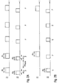
- FIGS. 2A and 2B For example, the differences in the application of the first and second stimuli 21 and 22 in the first and second operating modes are shown graphically.
- Fig. 2A For example, first time intervals ⁇ t 1 and second time intervals ⁇ t 2 are plotted against time t, during which first stimuli 21 and second stimuli 22 are generated in the first operating mode and administered to the patient.
- the time intervals ⁇ t 1 and ⁇ t 2 are each represented by rectangles.
- Out Fig. 2A shows that in the first operating mode, the generation and application of the unspecific second stimuli 22 is coupled to the generation and application of the specific first stimuli 21.
- the time intervals ⁇ t 1 and ⁇ t 2 occur in pairs in the learning phase.
- a non-specific second stimulus 22 also calls without an additional specific first stimulus 21, a therapeutic effect such as a specific first stimulus 21 is evident. Before this learning phase, a nonspecific second stimulus 22 would have produced no therapeutic effect.
- the duration of the time intervals ⁇ t 1 in which the specific first stimuli 21 are applied is, for example, between 30 Minutes and 6 hours, but may also be outside this range.
- the duration of the time intervals ⁇ t 2 , in which the unspecific second stimuli 22 are applied is between 10 minutes and 6 hours, but may also be outside this range.
- overlap in the first mode of operation the periods of time .DELTA.t 1 with the respective associated periods .DELTA.t 2 .
- This overlap ⁇ t 12 is, for example, at least 10% or 20% or 30% or 40% or 50% or 60% or 70% or 80% or at least 90% or even 100% of the respective time interval ⁇ t 2 .
- .DELTA.t 1 and .DELTA.t 2 can as in Fig. 2A illustrated that the period of time .DELTA.t 2 begin first, but it is alternatively also possible that the time interval .DELTA.t 1 is started.
- pauses are observed whose length ⁇ t pause can be between 3 hours and 24 hours, for example.
- Both the lengths of the time intervals ⁇ t 1 and ⁇ t 2 and the overlap periods ⁇ t 12 and the pause pauses ⁇ t pause can be varied during a stimulation phase.
- the duration of the learning phase ie the duration in which the device is operated in the first operating mode, may be predetermined and may, for example, comprise a predetermined number of paired time intervals ⁇ t 1 and ⁇ t 2 .
- first stimuli 21 and second stimuli 22 may be applied, the time interval ⁇ t 2 starting 15 minutes before the time interval ⁇ t 1 and both time periods ⁇ t 1 and ⁇ t 2 thus end simultaneously. After a break ⁇ t break of eg 6 hours, this process could be repeated. In order to achieve a rapid learning or conditioning of the nervous system, the number of learning events, ie the paired administration of first and second stimuli 21 and 22, could be further increased compared to the above example.
- the periods of time .DELTA.t 1 and At 2 could be reduced to 3 and 3.125 hours, wherein the time period begins .DELTA.t 2 7.5 minutes prior to the time interval .DELTA.t. 1 After a pause ⁇ t break of eg 3 hours, the coupled stimulation could be redone .
- a learning effect may possibly already occur after two applications of coupled first and second stimuli 21 and 22.
- the conditioning of the nervous system in order to make the conditioning of the nervous system as robust as possible and to be able to use the conditioning in the actual stimulation phase as long as possible, e.g. 10 to 50 pairs applications in the learning phase, i. the first operating mode.
- each time interval ⁇ t 2 it is not necessary for each time interval ⁇ t 2 to be assigned to one of the time segments ⁇ t 1 .
- a time interval ⁇ t 1 or ⁇ t 2 can be inserted which is not coupled to an associated time interval ⁇ t 2 or ⁇ t 1 and during which only first stimuli 21 or second stimuli 22 be generated and applied.
- at least 50% or 60% or 70% or 80% or 90% or even 100% of the time intervals ⁇ t 2 can be coupled to an associated time interval ⁇ t 1 .
- at least 50% or 60% or 70% or 80% or 90% or even 100% of the time segments ⁇ t 1 can be coupled to an associated time interval ⁇ t 2 .
- the control unit 10 switches to the second operating mode.
- Exemplary are in Fig. 2B the time intervals .DELTA.t 1 and .DELTA.t 2 plotted against each other during the time t, during which the first stimuli 21 and the second stimuli 22 are generated and applied in the second operating mode.
- nonspecific second stimuli 22 also have a therapeutic effect due to the conditioning of the nervous system of the patient achieved in the learning phase.
- the learning phase not primarily couples consisting of first and second stimuli 21 and 22 are applied; on the contrary, only second stimuli 22 which are not applied to the application of a first stimulus 21 are repeatedly applied during a time interval ⁇ t 2 are coupled.
- the second operating mode at least 10% or 20% or 30% or 40% or 50% or 60% or 70% or 80% or 90% of the time intervals ⁇ t 2 are not assigned a time interval ⁇ t 1 , ie the number of time periods ⁇ t is altogether 1 is smaller than the number of second time intervals ⁇ t 2 in the second operating mode.
- the second operating mode it is also possible to insert periods of time ⁇ t 1 which are not coupled to a time interval ⁇ t 2 . According to a further embodiment, it can also be provided, for example, that in the second operating mode, no time interval ⁇ t 1 is assigned to all time intervals ⁇ t 2 .
- the pairs "P" consisting of specific and unspecific stimuli 21 and 22 and the non-specific stimuli "U” applied alone can be used in the second operating mode, e.g. in periodic sequences, e.g. in the following order: P-P-U-U-U-P-P-U-U-U-P-U-U-U -...
- the stimulation effect achieved by the device 100 can be controlled, for example, with the aid of a measuring unit.
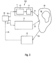
- An apparatus 300 incorporating such a measuring unit 15 is shown schematically in FIG Fig. 3 shown.
- the remaining Components of the device 300 are identical to those of FIG Fig. 1
- the measuring unit 15 receives one or more measurement signals 25 measured on the patient, optionally converts these into electrical signals 26 and supplies them to the control unit 10.
- the neuronal activity in the stimulated target area ie, for example, the neuronal activity of the in Fig. 3 schematically illustrated neuron population 30, or a region associated with the neuron population 30 are measured.
- the measuring unit 15 may be implanted in the form of one or more sensors in the body of the patient.
- deep brain electrodes, sub- or epidural brain electrodes, subcutaneous EEG electrodes and sub- or epidural spinal cord electrodes can serve as invasive sensors.
- electrodes to be attached to peripheral nerves can be used as sensors.
- the invasive sensor may for example be the same electrode 14, which is also used for the application of the first stimuli 21.
- the measurement signals 25 can be recorded in the intervals between the administration of the specific first stimuli 21, but in particular also during the exclusive administration of the unspecific second stimuli 22. If the neuronal activity of the target population 30 is measured, the amplitude of the pathological oscillations in typical frequency ranges of the local field potentials can be determined, eg for akinetic parkinsonian patients, the integral power in the beta frequency range between 10 and 30 Hz. With an effective stimulation, this amplitude decreases from. If the stimulation effect of the non-specific second stimuli 22 applied alone is satisfied in the second operating mode and the measured amplitude exceeds a predefined threshold value, then the next learning phase can take place in the first operating mode. Thereafter, the actual stimulation can be performed again in the second operating mode.
- the threshold value can be set by the doctor individually for the respective patient.
- typical values may be chosen as a default for the threshold, e.g. the mean of the amplitude plus twice the standard deviation in ranges of the frequency spectrum without frequency peaks and above e.g. 70 Hz.
- one or more non-invasive sensors may also be employed, such as e.g. Electroencephalography (EEG) electrodes, magnetoencephalography (MEG) sensors and electromyography (EMG) electrodes.
- EEG Electroencephalography
- MEG magnetoencephalography
- EMG electromyography
- the pathological oscillatory activity in the tremor frequency range or the lack of movement (in the sense of a reduction of the total movements) are measured via an accelerometer. If a predetermined value of the tremor activity is exceeded or falls below a critical value of the average hourly activity (outside the night time), e.g. the next learning phase in the first operating mode.
- two threshold values A L and A S can be predetermined, with which the amplitude of the pathological neuronal activity of the neuron population 30 measured by the measuring unit 15 is compared.
- the threshold value A L can be greater than the threshold value A S and represent the coarser of the two threshold values. If the amplitude of the beta-band activity exceeds the value A L , the system switches from the second operating mode to the first operating mode and carries out a new learning phase.
- the device 300 will not be switched to the first mode of operation but the device 300 will remain in the actual pacing phase, but more pairs "P" will become specific first stimuli 21 and non-specific second stimuli 22 applied.
- a subsequence (-UUUUU-) consisting only of non-specific stimuli "U” can be skipped and it is skipped to the next section in the sequence which has pairs "P" of specific and unspecific stimuli 21 and 22.
- this percentage of the pairs "P" can be increased by a certain percentage when the threshold value A S is exceeded.
- the threshold A S is exceeded.
- this percentage may be increased by 20% to 50%.
- the transition from the second to the first mode of operation may also be controlled by the patient through an external patient programmer. This means that the patient has the option of pressing a button on a small, handy external device if he does not feel sufficiently treated, eg if his tremor or his immobility are too strong.
- the control unit 10 then switches from the second operating mode into the first operating mode, that is to say into a new learning phase.
- the predefined mode here means that this switchover to the first operating mode is already triggered by the first keypress of the patient.
- the device 100 or 300 can also be set by the doctor so that only after a smaller number of such keystrokes per predetermined time interval, for example, after 3 keystrokes per half hour, switching to the first operating mode.
- the device 100 or 300 registers the number and times of keystrokes. This information can be read out by the physician by means of an external programming device intended for the physician.
- the second operating mode returns to the first operating mode, that is, into the learning phase.
- therapy control by means of the measuring unit 15 is not necessarily required, i. this switching mode may be implemented in both device 100 and device 300.
- the second stimulation unit 12 may include, for example, a loudspeaker, a light source (or image source) and / or a vibrator.
- the second stimuli 22 should be strong enough to be consciously perceived by the patient. For example, they should not be perceived as unpleasant, distracting or even distracting.
- the acoustic second stimuli 22 are for example a buzzer, a buzzer or a melody in question, which are generated during the periods .DELTA.t 2 from the speaker.
- optical signals are to be used as second stimuli 22, these can be, for example, abstract or representational patterns which are either static or change over time during the time periods ⁇ t 2 , eg a flower that moves in the wind, a fish that moves in the water Tactile stimuli or vibration stimuli may be vibrations with patient perceivable frequencies generated during periods of time ⁇ t 2 from a mechanical vibrator.
- Perceptible vibration stimuli can have frequencies in the range of 10 to 160 Hz or even higher, while tactile stimuli have significantly lower frequencies, for example less than 1 Hz.
- Mixed forms of tactile and vibratory stimuli can also be used.
- the tactile or vibratory For example, stimuli can be selected as pleasant by the patient himself. By means of the vibrator can also be exercised during the periods .DELTA.t 2 on the skin of the patient a slight, pleasant massaging effect.
- the non-specific second stimuli 22 can be continuously administered to the patient from the beginning to the end of a respective time interval ⁇ t 2 .
- application pauses may also be maintained during the time intervals ⁇ t 2 , for example the second stimuli 22 may be administered at specific time intervals with intervening application pauses during the periods ⁇ t 2 .
- These time patterns can also be varied, eg stochastic or deterministic or mixed stochastically deterministic. It can be provided that the second stimuli 22 are applied during at least 60% or 70% or 80% or 90% of the time duration of a respective time interval ⁇ t 2 .
- first stimuli 21 desynchronizing electrical stimulation signals are used or electrical stimulation signals that cause at least a reduction in the coincidence rate of the diseased neurons.
- the stimulation electrode 14, by means of which the first stimuli 21 are transmitted to the brain 29 or spinal cord 29 of the patient, may, for example, have one or two or more stimulation contact surfaces which are in contact with the tissue of the brain 29 or spinal cord 29 after implantation and over the first electrical stimuli 21 are applied.
- the stimulation electrode 14 consists of an insulated electrode shaft 50 and at least one, for example, two or more stimulation contact surfaces, which have been introduced into the electrode shaft 50.
- the stimulation electrode 14 includes four stimulation pads 51, 52, 53, and 54 Electrode shaft 50 and stimulation pads 51-54 may be made of a biocompatible material.
- the stimulation pads 51 to 54 are electrically conductive, for example, they are made of a metal, and are located after the implantation in direct electrical contact with the nerve tissue.
- each of the stimulation contact surfaces 51 to 54 can be activated via its own supply line 55, or the recorded measurement signals can be dissipated via the supply lines 55.
- two or more stimulation pads 51 to 54 may be connected to the same lead 55.
- the electrode 14 may have a reference electrode 56 whose surface may be larger than that of the stimulation contact surfaces 51 to 54.
- the reference electrode 56 is used in the stimulation of the nerve tissue to generate a reference potential.
- one of the stimulation pads 51 to 54 may be used for this purpose. That is, it can either be stimulated unipolarly between a single stimulation contact surface 51 to 54 and the reference electrode 56 (or the housing of the generator unit 13) or bipolar between different stimulation contact surfaces 51 to 54.
- the electrode 14 can also be used as a measuring unit 15 within the device 300. In this case, measuring signals are recorded via at least one of the contact surfaces 51 to 54.
- the stimulation pads 51 to 54 may be connected to the generator unit 13 via cables or via telemetric connections.
- the plurality of stimulation pads 51-54 allow separate regions of the brain 29 or spinal cord 29 to be separately stimulated via the individual stimulation pads 51-54.
- each of the stimulation contact surfaces 51 to 54 may be connected via a separate connecting line 55 to the generator unit 13. This makes it possible for the generator unit 13 to generate specific first stimuli 21 for each individual one of the stimulation contact surfaces 51 to 54.
- the stimulation contact surfaces 51 to 54 may be implanted in the patient such that the first stimuli 21 applied to the tissue are transmitted via nerve leads to different target areas located in the brain 29 and / or spinal cord 29. Consequently, 100 or 300 different target areas in the brain 29 and / or Rükkenmark 29 can be stimulated by the device 100 or 300 during the same stimulation period .DELTA.t 1 with possibly different and / or time-shifted first stimuli 21.
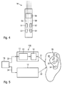
- the neuron population 30 which has a pathologically synchronous and oscillatory activity, is administered by means of the stimulation electrode 14 first stimuli 21, which in the Neuron population 30, a so-called reset, effect the phase of neuronal activity of the stimulated neurons.
- the phase of the stimulated neurons is set to a particular phase value, eg 0 °, independent of the current phase value.
- the phase of neuronal activity of the diseased neuron population 30 is controlled by targeted stimulation.
- the diseased neuron population 30 is split into a number of subpopulations, which in Fig. 5 are shown schematically and are identified by the reference numerals 31, 32, 33 and 34.
- the neurons are still synchronous after phase-reset and continue to fire at the same pathological frequency, but each of the sub-populations 31 to 34 has the phase imposed by the stimulation stimulus on their neuronal activity. This means that the neuronal activities of the individual subpopulations 31 to 34 after the resetting of their phases continue to have an approximately sinusoidal course with the same pathological frequency, but different phases.
- the stimulation contact surfaces 51 to 54 may be placed on or in the patient's brain or spinal cord tissue 29 such that the first stimuli 21 applied by the stimulation contact surface 51 irritate the subpopulation 31 and reset its neuronal phase and the first stimuli applied by the stimulation contact surface 52 21 irritate the subpopulation 52 and reset its neuronal phase.
- the stimulation contact surface 53 or 54 with respect to the subpopulation 33 or 34.
- the condition created by the stimulation is unstable with at least two subpopulations, and the entire neuron population 30 rapidly approaches a state of complete desynchronization in which the neurons fire uncorrelated.
- the desired state that is the complete desynchronization, is thus not immediately present after the application of the stimulation signals via the stimulation electrode 14, but usually occurs within a few periods or even less than one period of the pathological frequency.
- One theory for explaining the stimulation success is based on the fact that the ultimately desired desynchronization is made possible by the morbidly increased interaction between the neurons.
- a self-organization process is used, which is responsible for the morbid synchronization. It causes a division of a total population 30 into subpopulations 31 to 34 with different phases followed by a desynchronization. In contrast, without pathologically enhanced interaction of the neurons, no desynchronization would occur.
- the electrical stimulation with the device 100 or 300 can reorganize the connectivity of the disturbed neural networks, so that long-lasting therapeutic effects can be achieved.
- the achieved synaptic remodeling is of great importance for the effective treatment of neurological or psychiatric disorders.
- stimulation signals with which the phases of the stimulated neurons can be controlled, differently designed stimulation signals, such as high-frequency, continuously applied high-frequency pulse trains, the long-lasting therapeutic effects described above typically could not be achieved, with the result that would have to be stimulated permanently and at relatively high currents.
- stimulation forms described here only little energy introduced externally into the neuron system is needed to achieve a therapeutic effect. Due to the comparatively low energy input into the body of the patient and the often very quickly achieved stimulation results, by means of the device 100 and 300 often associated with an electrical nerve stimulation dysesthesia or paresthesia (painful discomfort) can be significantly reduced.
- stimulation signals that cause the phase of neurons to be reset can be delivered in a time-delayed manner via the different stimulation contact surfaces 51 to 54 to the respective stimulated nerve tissue.
- the stimulation signals may be e.g. out of phase or applied with different polarity, so that they also result in a delayed reset of the phases of the different subpopulations 31 to 34.
- the device 100 can be operated, for example, in a so-called "open loop” mode, in which the generator unit 13 generates predetermined first stimuli 21 and these are emitted via the stimulation contact surfaces 51 to 54 to the nerve tissue. Furthermore, the device 100 can also be connected to the in Fig. 3 shown device 300, which represents a so-called "closed loop” system. The device 300 additionally contains the Measuring unit 15, which provides one or more recorded on the patient measurement signals 26 and forwards them to the control unit 10.
- the control unit 10 detects the presence and / or the expression of one or more pathological features on the basis of the measurement signals 26 received by the measuring unit 15. For example, as already explained above, the amplitude or the amount of the neuronal activity can be measured, compared with one or more predetermined threshold values and, depending on the result of the comparison, a specific operating mode can be selected.
- the generator unit 13 can be configured such that a stimulation or the first operating mode is started as soon as the predetermined threshold value is exceeded.
- the strength of the first stimuli 21 can be adjusted on the basis of the measurement signals 26 received by the measuring unit 15.
- one or more threshold values can be preset, and when the amplitude or the magnitude of the measurement signals 26 exceeds a specific threshold value, a specific strength of the first stimuli 21 is set.
- the measuring signals 26 recorded by the measuring unit 15 are used directly or optionally after one or more processing steps as first stimuli 21 and are fed by the generator unit 13 into the stimulation electrode 14.
- the measurement signals 26 can be amplified and, if appropriate after mathematical calculation (for example, after mixing of the measurement signals), processed with a time delay and linear and / or nonlinear computation steps and combinations and fed into the stimulation electrode 14.
- the billing mode is chosen in such a way that the pathological neuronal activity is counteracted and the stimulation signal decreases with decreasing pathological neuronal activity also disappears or is at least significantly reduced in strength.
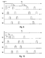
- the first stimuli 21 applied to the stimulation contact surfaces 51 to 54 are plotted against the time t.
- the in Fig. 6 shown period represents a section of a period of time .DELTA.t 1.
- the illustrated stimulation can be continued until the end of the period .DELTA.t 1 .
- each of the stimulation pads 51-54 periodically applies the first stimulus 21 to the respective area of tissue on which the stimulation pads 51-54 are placed.
- the frequency f 21 at which the first stimuli 21 are repeated per stimulation contact surface 51 to 54 can be in the range of 1 to 30 Hz and in particular in the range of 1 to 20 Hz or in the range of 5 to 20 Hz or in the range of 10 to 30 Hz, but can also accept smaller or larger values.
- the first stimuli 21 are administered via the individual stimulation contact surfaces 51 to 54 with a time delay between the individual stimulation contact surfaces 51 to 54.
- the beginning of temporally successive first stimuli 21 applied by different stimulation contact surfaces 51 to 54 can be delayed by a time ⁇ T j, j + 1 shifted.
- the time delay ⁇ T j, j + 1 between any two successive first stimuli 21 may, for example, be in the range of one Nth of the period 1 / f 21 .
- the delay ⁇ T j, j + 1 is then 1 / (4 xf 21 ).
- the frequency f 21 may, for example, be in the range of the mean frequency of the pathologically rhythmic activity of the target network.
- the mean frequency is typically in the range of 1 to 30 Hz, but may be outside this range. It should be noted that the frequency with which the affected neurons fire synchronously in neurological and psychiatric disorders is usually not constant, but may well be variable and, moreover, shows individual deviations in each patient.
- first stimuli 21 for example, current- or voltage-controlled pulses can be used.
- a first stimulus 21 may be as in FIG Fig. 7 be shown consisting of several individual pulses 210 existing pulse train.
- the pulse trains 21 may each consist of 1 to 100, in particular 2 to 10, electric charge-balanced individual pulses 210.
- the pulse trains 21 are applied, for example, as a sequence with up to 20 or more pulse trains. Within a sequence, the pulse trains 21 are repeated at the frequency f 21 in the range of 1 to 30 Hz.
- the individual pulses 210 are repeated at a frequency f 210 in the range from 50 to 500 Hz, in particular in the range from 100 to 150 Hz.
- the individual pulses 210 may be current- or voltage-controlled pulses which are composed of an initial pulse component 211 and a pulse component 212 flowing in the opposite direction, the polarity of the two pulse components 211 and 212 being opposite to that in FIG Fig. 8 shown polarity can also be reversed.
- the duration 213 of the pulse component 211 is in the range between 1 ⁇ s and 450 ⁇ s.
- the amplitude 214 of the pulse component 211 is in the range between 0 mA and 25 mA in the case of current-controlled pulses and in the range of 0 to 20 V in the case of voltage-controlled pulses.
- the amplitude of the pulse component 212 is less than the amplitude 214 of the pulse component 211 the duration of the pulse portion 212 is longer than that of the pulse portion 211.
- the pulse portions 211 and 212 are ideally dimensioned so that the charge that is transmitted through them is the same for both pulse portions 211 and 212, ie the in Fig. 8 hatched areas are the same size. As a result, by a single pulse 210 as much charge is introduced into the tissue as is removed from the tissue.
- rectangular shape of the individual pulses 210 represents an ideal shape. Depending on the quality of the individual pulses 210 generating electronics is deviated from the ideal rectangular shape.
- generator unit 13 may also generate differently configured stimulation signals, e.g. temporally continuous stimulus pattern.
- stimulation signals e.g. temporally continuous stimulus pattern.
- the signal forms described above and their parameters are only to be understood as examples. It may well be provided that deviates from the above-mentioned waveforms and their parameters.
- the strictly periodic stimulation pattern shown can be deviated in different ways.
- the time delay ⁇ T j, j + 1 between two successive first stimuli 21 does not necessarily have to be always the same. It can certainly be provided that the time intervals between the individual first stimuli 21 are chosen differently.
- the delay times can also be varied during the treatment of a patient. Also, the Delay times are adjusted with respect to the physiological signal transit times.
- breaks can be provided during which no stimulation takes place. Such a break is exemplary in Fig. 9 shown.
- the pauses can be maintained after any number of stimulations. For example, stimulation may be performed during n consecutive periods of length T 21 , followed by a pause during m periods of length T 21 without stimulation, where n and m are small integers, eg in the range of 1 to 10.
- This scheme can be either periodically continued or modified stochastically and / or deterministically, eg chaotically.
- Fig. 6 Another possibility of which in Fig. 6 The deviation from the strictly periodic stimulation pattern shown is to vary the time sequence of the individual first stimuli 21 stochastically or deterministically or mixed stochastically-deterministically.
- the period in which the stimulation contact surfaces 51 to 54 apply the first stimuli 21 can be varied per period T 21 (or else in other time steps), as shown by way of example in FIG Fig. 10 is shown.
- This variation can be stochastic or deterministic or mixed stochastic-deterministic.
- stimulation pads 51 to 54 may be used for stimulation, and the stimulation pads involved in the stimulation may be varied in each time interval. Also this variation can be stochastic or deterministic or mixed stochastically-deterministic.
- All of the stimulation forms described above can also be performed by means of the device 300 in a "closed loop" mode. Concerning. the in Fig. 9 shown stimulation form, the start time and the length of the break can be selected, for example, demand-controlled.
- the closed loop mode of the device 300 may be configured such that the measurement signals 26 received by the measuring unit 15 are converted by the generator unit 13 directly or optionally after one or more processing steps into electrical first stimuli 21 are implemented and applied by the stimulation electrode 14.
- the device 300 does not necessarily have to contain at least two pacing pads.
- This type of stimulation in which the measured signals recorded on the patient are fed back into the body of the patient, could in principle also be carried out with only a single stimulation contact surface, however, it is also possible to provide any, larger number of stimulation contact surfaces.
- the "closed loop” mode described above can also be used for desynchronization of a neuron population with a morbidly synchronous and oscillatory neuronal activity.
- the measurement signals 26 can be amplified, for example, and, if appropriate after mathematical calculation (eg, after mixing the measurement signals) with a time delay and linear and / or non-linear calculation steps, used as first stimuli 21 for the electrical stimulation.
- the billing mode can be chosen so that the pathological neuronal Activity is counteracted and the stimulation signal with decreasing pathological neuronal activity also disappears or at least significantly reduced in its strength.
- the measurement signal 26 can be filtered and / or amplified and / or time-delayed, for example, before the signal processed in this way is fed into the stimulation electrode 14 and applied by the stimulation contact surface (s) becomes.
- the measurement signal 26 has been recorded by means of an EEG electrode and reflects the pathological activity in the target area. Accordingly, the measuring signal 26 is a sinusoidal oscillation with a frequency in the range of 1 to 30 Hz. Furthermore, it is assumed by way of example that the measuring signal 26 has a frequency of 5 Hz.
- the measurement signal 26 can be filtered by means of a bandpass filter with a passband in the range of 5 Hz and amplified by means of an amplifier so that it has suitable levels for electrical brain or spinal cord stimulation. Subsequently, the resulting amplified sinusoidal oscillation is used to drive the stimulation electrode 14.
- the measurement signal 26 can be compared with the in Fig. 6 shown time delays ⁇ T j, j + 1 are applied before it is fed as a first stimulus 21 in the corresponding stimulation pads.
- the in Fig. 6 shown rectangular stimulation signals 21 sine wave applied at a frequency of 5 Hz.
- a measurement signal 26 obtained by the measurement unit 15 can be subjected to non-linear processing before it is used as the first stimulus 21 for the electrical brain or spinal cord stimulation is explained below by means of an example.
- the measurement signal 26 can also be filtered and / or amplified and / or acted upon here with a time delay.
- the starting point is an equation for the stimulation signal S (t) (first stimulus):
- S t K ⁇ Z ⁇ 2 t ⁇ Z ⁇ * ⁇ t - ⁇
- K is a gain which can be suitably selected
- Z (t) a mean state variable of the measurement signal.
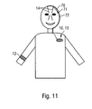
- Fig. 11 the device 100 or 300 is shown schematically during its intended operation.
- at least one stimulation electrode 14 has been implanted in one or both sides of the brain of a patient.
- the stimulation electrodes 14 placed in one or more of the target areas mentioned above are each connected to the generator unit 13 by a cable 70 via a connector 71 and by a continuing cable 72.
- the generator unit 13 in the present embodiment also includes the control unit 10.
- the above-mentioned components of the apparatus 100 are implanted in the body of the patient.
- the connecting cables 70 and 72 and the connector 71 are implanted under the skin.
- pectorally implanted generator unit 13 and a smaller generator can be implanted directly in the borehole.
- the infection rate in the generator pocket can be reduced and breaks in the connecting cables 70 and 72 can be avoided.
- a semi-implant with a radio link can also be used.
- the device 300 also contains a measuring unit 15.
- the second stimulation unit 12 for generating the non-specific second stimuli 22 is attached to the arm of the patient in the present example.
- the second stimulation unit 12 can with the in the Body of the patient located control unit 10 communicate for example via a radio link.
- the second stimulation unit 12 for generating the nonspecific second stimuli 22 is shown.
- the second stimulation unit 12 is designed as a so-called "conditioning clock", which is comfortable for the patient to wear.
- Fig. 12A is the front view
- Fig. 12B the rear view of the conditioning clock 12 is shown.
- the conditioning watch 12 consists of a middle part 80, bracelets 81, a closure part 82 and associated holes 83. Alternatively, a hook-and-loop fastener or any other equivalent closure may be used.
- the middle part 80 contains a loudspeaker 84 for generating unspecific acoustic signals 22, for example a melody or a pleasant buzzer, and a display 85 for generating a pleasant, nonglaring non-specific optical stimulus 22, for example a flower moving in the wind or an abstract light pattern with bright and warm colors.
- the conditioning watch 12 may be equipped with one or more vibrators 86 that generate nonspecific tactile and / or vibratory stimuli 22.
- the vibrators can be operated with frequencies of less than 1 Hz.
- the moving parts of the vibrators 86 may be oriented so that they can better realize pressure stimuli, ie, the main direction of movement of the vibrators 86 should be directed into the skin.
- the tactile stimuli 22 could also be generated by pressure actuators or slowly moving relative to the skin elements, which may be integrated into the conditioning watch, for example. If by means of the vibrators 86 vibratory stimuli 22 are to be generated, vibration frequencies in the range of 10 to 160 Hz or more can be used. In this case, the moving parts of the vibrators 86 may have a pronounced moving direction substantially parallel to the skin. The vibrators 86 can are also operated so that they simultaneously produce tactile and vibratory stimuli 22.
- the conditioning clock 12 may also be designed to have only one non-specific stimulus 22 of a sensory modality, e.g. only an optical stimulus, generated.
- the power supply of the conditioning clock 12 is effected by a battery and / or solar cells and / or a mechanical flywheel in the interior of the conditioning clock 12.
- the conditioning clock 12 may additionally include an accelerometer with which the diseased oscillatory activity, e.g. of morbid tremor, or to measure the average level of activity of the patient.
- the average level of activity of the patient reflects the slowdown or depletion of the patient's movement or immobility (i.e., brady, hypo, and akinesia).
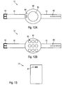
- FIG. 13 Another embodiment of the second stimulation unit 12 is Fig. 13 shown schematically. This is, for example, a cellphone-shaped stimulator that can be worn, for example, in the shirt pocket or trouser pocket of the patient and that generates non-specific acoustic stimuli 22 by means of a loudspeaker 87.
- an external programming device for the physician can be provided with which the parameters of the control unit 10, the generator unit 13 and / or the unspecific, physiological stimulation unit 12 can be adjusted.
- the patient can also be provided with an external programming device with which the patient can issue the stimulation devices or can modify parameters of the stimulation units 11 and 12 within narrow limits prescribed by the physician.
- the programming device intended for the patient may include the functionality already described above, by means of which the Patient independently, for example by pressing a button, a switch from the second mode of operation in the first mode of operation, ie the learning phase, can cause if he does not feel adequately treated, so if, for example, his tremor or immobility are too strong.
- the programming devices can communicate, for example via radio links with the respective components of the stimulation device.
Applications Claiming Priority (2)
| Application Number | Priority Date | Filing Date | Title |
|---|---|---|---|
| DE102008052078A DE102008052078B4 (de) | 2008-10-17 | 2008-10-17 | Vorrichtung zur konditionierten desynchronisierenden Stimulation |
| PCT/EP2009/007452 WO2010043413A1 (de) | 2008-10-17 | 2009-10-16 | Vorrichtung und verfahren zur konditionierten desynchronisierenden stimulation |
Publications (2)
| Publication Number | Publication Date |
|---|---|
| EP2358430A1 EP2358430A1 (de) | 2011-08-24 |
| EP2358430B1 true EP2358430B1 (de) | 2013-01-23 |
Family
ID=41393642
Family Applications (1)
| Application Number | Title | Priority Date | Filing Date |
|---|---|---|---|
| EP09741225A Not-in-force EP2358430B1 (de) | 2008-10-17 | 2009-10-16 | Vorrichtung zur konditionierten desynchronisierenden stimulation |
Country Status (7)
| Country | Link |
|---|---|
| US (1) | US8463378B2 (es) |
| EP (1) | EP2358430B1 (es) |
| JP (1) | JP5275471B2 (es) |
| CN (1) | CN102186536B (es) |
| DE (1) | DE102008052078B4 (es) |
| ES (1) | ES2401832T3 (es) |
| WO (1) | WO2010043413A1 (es) |
Families Citing this family (68)
| Publication number | Priority date | Publication date | Assignee | Title |
|---|---|---|---|---|
| US20090204173A1 (en) | 2007-11-05 | 2009-08-13 | Zi-Ping Fang | Multi-Frequency Neural Treatments and Associated Systems and Methods |
| US9089707B2 (en) | 2008-07-02 | 2015-07-28 | The Board Of Regents, The University Of Texas System | Systems, methods and devices for paired plasticity |
| US9327121B2 (en) | 2011-09-08 | 2016-05-03 | Nevro Corporation | Selective high frequency spinal cord modulation for inhibiting pain, including cephalic and/or total body pain with reduced side effects, and associated systems and methods |
| US8255057B2 (en) | 2009-01-29 | 2012-08-28 | Nevro Corporation | Systems and methods for producing asynchronous neural responses to treat pain and/or other patient conditions |
| EP2243510B1 (en) | 2009-04-22 | 2014-04-09 | Nevro Corporation | Sytems for selective high frequency spinal cord modulation for inhibiting pain with reduced side effects |
| WO2010124128A1 (en) | 2009-04-22 | 2010-10-28 | Nevro Corporation | Spinal cord modulation for inducing paresthetic and anesthetic effects, and associated systems and methods |
| US8498710B2 (en) | 2009-07-28 | 2013-07-30 | Nevro Corporation | Linked area parameter adjustment for spinal cord stimulation and associated systems and methods |
| DE102010000390A1 (de) | 2010-02-11 | 2011-08-11 | Forschungszentrum Jülich GmbH, 52428 | Vorrichtung und Verfahren zur Behandlung eines Patienten mit Vibrations-, Tast- und/oder Thermoreizen |
| DE102010016404A1 (de) * | 2010-04-12 | 2012-12-27 | Forschungszentrum Jülich GmbH | Vorrichtung und Verfahren zur konditionierten desynchronisierenden nicht-invasiven Stimulation |
| DE102010016461B4 (de) | 2010-04-15 | 2013-03-21 | Forschungszentrum Jülich GmbH | Vorrichtung zur Behandlung von Erkrankungen des Gehirns und/oder Rückenmarks mittels Neurofeedback |
| US8649874B2 (en) | 2010-11-30 | 2014-02-11 | Nevro Corporation | Extended pain relief via high frequency spinal cord modulation, and associated systems and methods |
| WO2012094484A1 (en) * | 2011-01-05 | 2012-07-12 | Stefanie Lattner | Method and apparatus for treating various neurological conditions |
| EP2747636B1 (en) | 2011-08-25 | 2019-03-20 | Insomnisolv, LLC | System for the treatment of insomnia |
| DE102012002437B4 (de) | 2012-02-08 | 2014-08-21 | Forschungszentrum Jülich GmbH | Vorrichtung zur Eichung einer invasiven, elektrischen und desynchronisierenden Neurostimulation |
| DE102012002436B4 (de) * | 2012-02-08 | 2014-08-21 | Forschungszentrum Jülich GmbH | Vorrichtung zur Eichung einer nicht-invasiven desynchronisierenden Neurostimulation |
| DE102012005030B4 (de) | 2012-03-12 | 2016-06-16 | Forschungszentrum Jülich GmbH | Vorrichtung und Verfahren zur Stimulation mit Thermoreizen |
| US10265527B2 (en) | 2012-04-17 | 2019-04-23 | Regents Of The University Of Minnesota | Multi-modal synchronization therapy |
| US9833614B1 (en) | 2012-06-22 | 2017-12-05 | Nevro Corp. | Autonomic nervous system control via high frequency spinal cord modulation, and associated systems and methods |
| EP2866888B1 (en) * | 2012-06-30 | 2018-11-07 | Boston Scientific Neuromodulation Corporation | System for compounding low-frequency sources for high-frequency neuromodulation |
| DE102012218057A1 (de) | 2012-10-02 | 2014-04-03 | Forschungszentrum Jülich GmbH | Vorrichtung und verfahren zur untersuchung einer krankhaften interaktion zwischen verschiedenen hirnarealen |
| AU2014207265B2 (en) * | 2013-01-21 | 2017-04-20 | Cala Health, Inc. | Devices and methods for controlling tremor |
| WO2014130865A2 (en) | 2013-02-22 | 2014-08-28 | Boston Scientific Neuromodulation Corporation | Neurostimulation system having increased flexibility for creating complex pulse trains |
| ES2675330T3 (es) * | 2013-03-15 | 2018-07-10 | The Regents Of The University Of Michigan | Estimulación auditiva-somatosensorial personalizada para el tratamiento de acúfenos |
| US9895539B1 (en) | 2013-06-10 | 2018-02-20 | Nevro Corp. | Methods and systems for disease treatment using electrical stimulation |
| DE102013013278A1 (de) * | 2013-08-08 | 2015-02-12 | Forschungszentrum Jülich GmbH | Vorrichtung und Verfahren zur Eichung einer akustischen desynchronisierenden Neurostimulation |
| DK3054912T3 (da) | 2013-10-07 | 2021-05-25 | Oy Neurosonic Finland Ltd | Fremgangsmåde og anordning til lindring af en persons stressrelaterede søvnforstyrrelse og reduktion af personens stressniveau |
| US10149978B1 (en) | 2013-11-07 | 2018-12-11 | Nevro Corp. | Spinal cord modulation for inhibiting pain via short pulse width waveforms, and associated systems and methods |
| WO2016049047A2 (en) | 2014-09-22 | 2016-03-31 | Boston Scientific Neuromodulation Corporation | Systems and methods for providing therapy using electrical stimulation to disrupt neuronal activity |
| CN106714678B (zh) | 2014-09-22 | 2020-03-20 | 波士顿科学神经调制公司 | 使用功率谱或信号关联性进行疼痛管理的设备和方法 |
| EP3197547A1 (en) | 2014-09-22 | 2017-08-02 | Boston Scientific Neuromodulation Corporation | Systems and methods for providing therapy to a patient using intermittent electrical stimulation |
| EP3197548A1 (en) | 2014-09-22 | 2017-08-02 | Boston Scientific Neuromodulation Corporation | Devices using a pathological frequency in electrical stimulation for pain management |
| WO2016049021A1 (en) | 2014-09-22 | 2016-03-31 | Boston Scientific Neuromodulation Corporation | Systems and methods for providing therapy using electrical stimulation to disrupt neuronal activity |
| DE102014115994B4 (de) * | 2014-11-03 | 2016-12-22 | Forschungszentrum Jülich GmbH | Vorrichtung zur effektiven invasiven desynchronisierenden Neurostimulation |
| DE102014115997B4 (de) * | 2014-11-03 | 2016-12-22 | Forschungszentrum Jülich GmbH | Vorrichtung zur effektiven nicht-invasiven desynchronisierenden Neurostimulation |
| DE102015101371A1 (de) | 2015-01-30 | 2016-08-04 | Forschungszentrum Jülich GmbH | Vorrichtung und Verfahren zur nicht-invasiven Neurostimulation mittels Mehrkanal-Bursts |
| DE102015101823A1 (de) * | 2015-02-09 | 2016-08-11 | Forschungszentrum Jülich GmbH | Vorrichtung und Verfahren zur Kalibrierung einer nicht-invasiven mechanisch taktilen und/oder thermischen Neurostimulation |
| US10052486B2 (en) * | 2015-04-06 | 2018-08-21 | Medtronic, Inc. | Timed delivery of electrical stimulation therapy |
| DE102015109988B4 (de) * | 2015-06-22 | 2017-04-27 | Forschungszentrum Jülich GmbH | Vorrichtung zur effektiven invasiven Zwei-Stufen-Neurostimulation |
| DE102015109986B4 (de) * | 2015-06-22 | 2017-04-27 | Forschungszentrum Jülich GmbH | Vorrichtung zur effektiven nicht-invasiven Zwei-Stufen-Neurostimulation |
| US10413737B2 (en) | 2015-09-25 | 2019-09-17 | Boston Scientific Neuromodulation Corporation | Systems and methods for providing therapy using electrical stimulation to disrupt neuronal activity |
| US11318310B1 (en) | 2015-10-26 | 2022-05-03 | Nevro Corp. | Neuromodulation for altering autonomic functions, and associated systems and methods |
| DE102015122888B4 (de) * | 2015-12-29 | 2017-12-21 | Forschungszentrum Jülich GmbH | Vorrichtung und Verfahren zur effektiven invasiven Mehrsegment-Neurostimulation |
| US20170209699A1 (en) | 2016-01-25 | 2017-07-27 | Nevro Corp. | Treatment of congestive heart failure with electrical stimulation, and associated systems and methods |
| DE102016104913B4 (de) * | 2016-03-16 | 2018-04-26 | Forschungszentrum Jülich GmbH | Vorrichtung zur effektiven, invasiven und amplitudenmodulierten Neurostimulation |
| US10799701B2 (en) | 2016-03-30 | 2020-10-13 | Nevro Corp. | Systems and methods for identifying and treating patients with high-frequency electrical signals |
| US11446504B1 (en) | 2016-05-27 | 2022-09-20 | Nevro Corp. | High frequency electromagnetic stimulation for modulating cells, including spontaneously active and quiescent cells, and associated systems and methods |
| US11213641B2 (en) | 2016-09-14 | 2022-01-04 | Healthy Humming, LLC | Therapeutic device for treatment of conditions relating to the sinuses, nasal cavities, ear, nose and throat |
| WO2018053079A1 (en) * | 2016-09-14 | 2018-03-22 | Bogan Consulting Services, P.A. | Therapeutic device for treatment of conditions relating to the sinuses, nasal cavities, ear, nose and throat |
| US11432993B2 (en) | 2016-09-14 | 2022-09-06 | Healthy Humming, LLC | Therapeutic device for treatment of conditions relating to the sinuses, nasal cavities, ear, nose and throat |
| US11305077B2 (en) | 2016-09-14 | 2022-04-19 | Healthy Humming, LLC | Therapeutic device for treatment of conditions relating to the sinuses, nasal cavities, ear, nose and throat |
| WO2019060298A1 (en) | 2017-09-19 | 2019-03-28 | Neuroenhancement Lab, LLC | METHOD AND APPARATUS FOR NEURO-ACTIVATION |
| WO2019099887A1 (en) | 2017-11-17 | 2019-05-23 | Boston Scientific Neuromodulation Corporation | Systems and methods for generating intermittent stimulation using electrical stimulation systems |
| US11717686B2 (en) | 2017-12-04 | 2023-08-08 | Neuroenhancement Lab, LLC | Method and apparatus for neuroenhancement to facilitate learning and performance |
| US11478603B2 (en) | 2017-12-31 | 2022-10-25 | Neuroenhancement Lab, LLC | Method and apparatus for neuroenhancement to enhance emotional response |
| US11364361B2 (en) | 2018-04-20 | 2022-06-21 | Neuroenhancement Lab, LLC | System and method for inducing sleep by transplanting mental states |
| WO2019246561A1 (en) * | 2018-06-22 | 2019-12-26 | The Board Of Trustees Of The Leland Stanford Junior University | Effective invasive multichannel desynchronizing stimulation |
| EP3810258A1 (en) * | 2018-06-22 | 2021-04-28 | Gretap AG | Medical treatment device and method for stimulating neurons of a patient to suppress a pathologically synchronous activity thereof |
| CN109078263A (zh) * | 2018-08-22 | 2018-12-25 | 广州欧欧医疗科技有限责任公司 | 一种耳鸣治疗仪系统 |
| WO2020049004A1 (en) * | 2018-09-03 | 2020-03-12 | Gretap Ag C/O Vtb Verwaltung, Treuhand Und Beratung Ag | Medical treatment device and method for stimulating neurons of a patient to suppress a pathologically synchronous activity of the neurons |
| US11839583B1 (en) | 2018-09-11 | 2023-12-12 | Encora, Inc. | Apparatus and method for reduction of neurological movement disorder symptoms using wearable device |
| US11701293B2 (en) | 2018-09-11 | 2023-07-18 | Encora, Inc. | Apparatus and method for reduction of neurological movement disorder symptoms using wearable device |
| WO2020056418A1 (en) | 2018-09-14 | 2020-03-19 | Neuroenhancement Lab, LLC | System and method of improving sleep |
| AU2020207940A1 (en) | 2019-01-17 | 2021-08-12 | Nevro Corp. | Sensory threshold and/or adaptation for neurological therapy screening and/or parameter selection, and associated systems and methods |
| US11590352B2 (en) | 2019-01-29 | 2023-02-28 | Nevro Corp. | Ramped therapeutic signals for modulating inhibitory interneurons, and associated systems and methods |
| US11786694B2 (en) | 2019-05-24 | 2023-10-17 | NeuroLight, Inc. | Device, method, and app for facilitating sleep |
| KR102244599B1 (ko) * | 2019-06-07 | 2021-04-23 | 한림대학교 산학협력단 | 이명 치료 모니터링 장치 및 방법 |
| CN110262336B (zh) * | 2019-06-18 | 2021-02-02 | 中国科学院自动化研究所 | 电流输出电路及包括其的经颅电刺激设备 |
| US11260231B2 (en) * | 2020-01-24 | 2022-03-01 | Medtronic, Inc. | Electrical stimulation modulation |
Family Cites Families (9)
| Publication number | Priority date | Publication date | Assignee | Title |
|---|---|---|---|---|
| US6944501B1 (en) * | 2000-04-05 | 2005-09-13 | Neurospace, Inc. | Neurostimulator involving stimulation strategies and process for using it |
| US6067470A (en) * | 1998-03-05 | 2000-05-23 | Mower Family Chf Treatment Irrevocable Trust | System and method for multiple site biphasic stimulation to revert ventricular arrhythmias |
| DE10233960B4 (de) * | 2002-07-29 | 2006-11-02 | Forschungszentrum Jülich GmbH | Vorrichtung zur bedarfsgesteuerten Modulation physiologischer und pathologischer neuronaler rhythmischer Aktivität im Gehirn mittels sensorischer Stimulation |
| DE10318071A1 (de) * | 2003-04-17 | 2004-11-25 | Forschungszentrum Jülich GmbH | Vorrichtung zur Desynchronisation von neuronaler Hirnaktivität |
| US20060020291A1 (en) | 2004-03-09 | 2006-01-26 | Gozani Shai N | Apparatus and method for performing nerve conduction studies with multiple neuromuscular electrodes |
| DE102004060514A1 (de) * | 2004-12-16 | 2006-06-29 | Forschungszentrum Jülich GmbH | Verfahren und Vorrichtung zur Desynchronisation neuronaler Hirnaktivität, Steuerung, sowie Verfahren zur Behandlung neuronaler und/oder psychiatrischer Erkrankungen |
| JP2006244343A (ja) * | 2005-03-07 | 2006-09-14 | Nissan Motor Co Ltd | ドライバ活性化誘導装置及びドライバ活性化誘導方法 |
| JP2007130424A (ja) * | 2005-11-09 | 2007-05-31 | Hirobumi Funamizu | 電気・磁気刺激方法、電気・磁気刺激装置及び電気・磁気刺激評価方法 |
| WO2009042170A1 (en) * | 2007-09-26 | 2009-04-02 | Medtronic, Inc. | Therapy program selection |
-
2008
- 2008-10-17 DE DE102008052078A patent/DE102008052078B4/de not_active Expired - Fee Related
-
2009
- 2009-10-16 WO PCT/EP2009/007452 patent/WO2010043413A1/de active Application Filing
- 2009-10-16 ES ES09741225T patent/ES2401832T3/es active Active
- 2009-10-16 EP EP09741225A patent/EP2358430B1/de not_active Not-in-force
- 2009-10-16 CN CN200980140942.7A patent/CN102186536B/zh not_active Expired - Fee Related
- 2009-10-16 US US13/124,571 patent/US8463378B2/en active Active
- 2009-10-16 JP JP2011531402A patent/JP5275471B2/ja not_active Expired - Fee Related
Also Published As
| Publication number | Publication date |
|---|---|
| WO2010043413A1 (de) | 2010-04-22 |
| DE102008052078B4 (de) | 2011-06-01 |
| JP5275471B2 (ja) | 2013-08-28 |
| ES2401832T3 (es) | 2013-04-24 |
| US20110201977A1 (en) | 2011-08-18 |
| JP2012505674A (ja) | 2012-03-08 |
| EP2358430A1 (de) | 2011-08-24 |
| US8463378B2 (en) | 2013-06-11 |
| DE102008052078A1 (de) | 2010-04-29 |
| CN102186536A (zh) | 2011-09-14 |
| CN102186536B (zh) | 2014-06-25 |
Similar Documents
| Publication | Publication Date | Title |
|---|---|---|
| EP2358430B1 (de) | Vorrichtung zur konditionierten desynchronisierenden stimulation | |
| EP2547398B1 (de) | Vorrichtung zur konditionierten desynchronisierenden nicht-invasiven stimulation | |
| DE102014117427B4 (de) | Vorrichtung zur effektiven nicht-invasiven Neurostimulation mittels variierender Reizsequenzen | |
| EP2103288B1 (de) | Vorrichtung zur auditorischen Stimulation | |
| EP2533747B1 (de) | Vorrichtung zur behandlung eines patienten mit vibrations-, tast- und/oder thermoreizen | |
| DE102015109986B4 (de) | Vorrichtung zur effektiven nicht-invasiven Zwei-Stufen-Neurostimulation | |
| DE102010016461B4 (de) | Vorrichtung zur Behandlung von Erkrankungen des Gehirns und/oder Rückenmarks mittels Neurofeedback | |
| DE102016104913B4 (de) | Vorrichtung zur effektiven, invasiven und amplitudenmodulierten Neurostimulation | |
| EP3397336B1 (de) | Vorrichtung zur effektiven invasiven mehrsegment-neurostimulation | |
| EP3285854B1 (de) | Vorrichtung zur effektiven invasiven zwei-stufen-neurostimulation | |
| EP3183031B1 (de) | Vorrichtung zur effektiven nicht-invasiven desynchronisierenden neurostimulation | |
| WO2016083516A1 (de) | Vorrichtung und verfahren zur effektiven invasiven neurostimulation mittels variierender reizsequenzen | |
| WO2016071234A1 (de) | Vorrichtung zur effektiven invasiven desynchronisierenden neurostimulation | |
| DE102009015723B4 (de) | Stimulationselektrode | |
| DE102008039387B4 (de) | Vorrichtung zur transkutanen Stimulation |
Legal Events
| Date | Code | Title | Description |
|---|---|---|---|
| PUAI | Public reference made under article 153(3) epc to a published international application that has entered the european phase |
Free format text: ORIGINAL CODE: 0009012 |
|
| 17P | Request for examination filed |
Effective date: 20110426 |
|
| AK | Designated contracting states |
Kind code of ref document: A1 Designated state(s): AT BE BG CH CY CZ DE DK EE ES FI FR GB GR HR HU IE IS IT LI LT LU LV MC MK MT NL NO PL PT RO SE SI SK SM TR |
|
| DAX | Request for extension of the european patent (deleted) | ||
| GRAP | Despatch of communication of intention to grant a patent |
Free format text: ORIGINAL CODE: EPIDOSNIGR1 |
|
| GRAS | Grant fee paid |
Free format text: ORIGINAL CODE: EPIDOSNIGR3 |
|
| GRAA | (expected) grant |
Free format text: ORIGINAL CODE: 0009210 |
|
| AK | Designated contracting states |
Kind code of ref document: B1 Designated state(s): AT BE BG CH CY CZ DE DK EE ES FI FR GB GR HR HU IE IS IT LI LT LU LV MC MK MT NL NO PL PT RO SE SI SK SM TR |
|
| REG | Reference to a national code |
Ref country code: GB Ref legal event code: FG4D Free format text: NOT ENGLISH |
|
| REG | Reference to a national code |
Ref country code: CH Ref legal event code: EP |
|
| REG | Reference to a national code |
Ref country code: AT Ref legal event code: REF Ref document number: 594631 Country of ref document: AT Kind code of ref document: T Effective date: 20130215 Ref country code: CH Ref legal event code: EP |
|
| REG | Reference to a national code |
Ref country code: IE Ref legal event code: FG4D Free format text: LANGUAGE OF EP DOCUMENT: GERMAN |
|
| REG | Reference to a national code |
Ref country code: DE Ref legal event code: R096 Ref document number: 502009006111 Country of ref document: DE Effective date: 20130321 |
|
| REG | Reference to a national code |
Ref country code: ES Ref legal event code: FG2A Ref document number: 2401832 Country of ref document: ES Kind code of ref document: T3 Effective date: 20130424 |
|
| REG | Reference to a national code |
Ref country code: CH Ref legal event code: NV Representative=s name: DR. GRAF AND PARTNER AG INTELLECTUAL PROPERTY, CH |
|
| REG | Reference to a national code |
Ref country code: LT Ref legal event code: MG4D |
|
| REG | Reference to a national code |
Ref country code: NL Ref legal event code: VDEP Effective date: 20130123 |
|
| PG25 | Lapsed in a contracting state [announced via postgrant information from national office to epo] |
Ref country code: BG Free format text: LAPSE BECAUSE OF FAILURE TO SUBMIT A TRANSLATION OF THE DESCRIPTION OR TO PAY THE FEE WITHIN THE PRESCRIBED TIME-LIMIT Effective date: 20130423 Ref country code: SE Free format text: LAPSE BECAUSE OF FAILURE TO SUBMIT A TRANSLATION OF THE DESCRIPTION OR TO PAY THE FEE WITHIN THE PRESCRIBED TIME-LIMIT Effective date: 20130123 Ref country code: NO Free format text: LAPSE BECAUSE OF FAILURE TO SUBMIT A TRANSLATION OF THE DESCRIPTION OR TO PAY THE FEE WITHIN THE PRESCRIBED TIME-LIMIT Effective date: 20130423 Ref country code: LT Free format text: LAPSE BECAUSE OF FAILURE TO SUBMIT A TRANSLATION OF THE DESCRIPTION OR TO PAY THE FEE WITHIN THE PRESCRIBED TIME-LIMIT Effective date: 20130123 Ref country code: IS Free format text: LAPSE BECAUSE OF FAILURE TO SUBMIT A TRANSLATION OF THE DESCRIPTION OR TO PAY THE FEE WITHIN THE PRESCRIBED TIME-LIMIT Effective date: 20130523 |
|
| PG25 | Lapsed in a contracting state [announced via postgrant information from national office to epo] |
Ref country code: PT Free format text: LAPSE BECAUSE OF FAILURE TO SUBMIT A TRANSLATION OF THE DESCRIPTION OR TO PAY THE FEE WITHIN THE PRESCRIBED TIME-LIMIT Effective date: 20130523 Ref country code: NL Free format text: LAPSE BECAUSE OF FAILURE TO SUBMIT A TRANSLATION OF THE DESCRIPTION OR TO PAY THE FEE WITHIN THE PRESCRIBED TIME-LIMIT Effective date: 20130123 Ref country code: GR Free format text: LAPSE BECAUSE OF FAILURE TO SUBMIT A TRANSLATION OF THE DESCRIPTION OR TO PAY THE FEE WITHIN THE PRESCRIBED TIME-LIMIT Effective date: 20130424 Ref country code: PL Free format text: LAPSE BECAUSE OF FAILURE TO SUBMIT A TRANSLATION OF THE DESCRIPTION OR TO PAY THE FEE WITHIN THE PRESCRIBED TIME-LIMIT Effective date: 20130123 Ref country code: FI Free format text: LAPSE BECAUSE OF FAILURE TO SUBMIT A TRANSLATION OF THE DESCRIPTION OR TO PAY THE FEE WITHIN THE PRESCRIBED TIME-LIMIT Effective date: 20130123 Ref country code: LV Free format text: LAPSE BECAUSE OF FAILURE TO SUBMIT A TRANSLATION OF THE DESCRIPTION OR TO PAY THE FEE WITHIN THE PRESCRIBED TIME-LIMIT Effective date: 20130123 Ref country code: SI Free format text: LAPSE BECAUSE OF FAILURE TO SUBMIT A TRANSLATION OF THE DESCRIPTION OR TO PAY THE FEE WITHIN THE PRESCRIBED TIME-LIMIT Effective date: 20130123 |
|
| PG25 | Lapsed in a contracting state [announced via postgrant information from national office to epo] |
Ref country code: HR Free format text: LAPSE BECAUSE OF FAILURE TO SUBMIT A TRANSLATION OF THE DESCRIPTION OR TO PAY THE FEE WITHIN THE PRESCRIBED TIME-LIMIT Effective date: 20130123 |
|
| PG25 | Lapsed in a contracting state [announced via postgrant information from national office to epo] |
Ref country code: DK Free format text: LAPSE BECAUSE OF FAILURE TO SUBMIT A TRANSLATION OF THE DESCRIPTION OR TO PAY THE FEE WITHIN THE PRESCRIBED TIME-LIMIT Effective date: 20130123 Ref country code: CZ Free format text: LAPSE BECAUSE OF FAILURE TO SUBMIT A TRANSLATION OF THE DESCRIPTION OR TO PAY THE FEE WITHIN THE PRESCRIBED TIME-LIMIT Effective date: 20130123 Ref country code: EE Free format text: LAPSE BECAUSE OF FAILURE TO SUBMIT A TRANSLATION OF THE DESCRIPTION OR TO PAY THE FEE WITHIN THE PRESCRIBED TIME-LIMIT Effective date: 20130123 Ref country code: SK Free format text: LAPSE BECAUSE OF FAILURE TO SUBMIT A TRANSLATION OF THE DESCRIPTION OR TO PAY THE FEE WITHIN THE PRESCRIBED TIME-LIMIT Effective date: 20130123 Ref country code: RO Free format text: LAPSE BECAUSE OF FAILURE TO SUBMIT A TRANSLATION OF THE DESCRIPTION OR TO PAY THE FEE WITHIN THE PRESCRIBED TIME-LIMIT Effective date: 20130123 |
|
| PG25 | Lapsed in a contracting state [announced via postgrant information from national office to epo] |
Ref country code: CY Free format text: LAPSE BECAUSE OF FAILURE TO SUBMIT A TRANSLATION OF THE DESCRIPTION OR TO PAY THE FEE WITHIN THE PRESCRIBED TIME-LIMIT Effective date: 20130123 |
|
| PLBE | No opposition filed within time limit |
Free format text: ORIGINAL CODE: 0009261 |
|
| STAA | Information on the status of an ep patent application or granted ep patent |
Free format text: STATUS: NO OPPOSITION FILED WITHIN TIME LIMIT |
|
| 26N | No opposition filed |
Effective date: 20131024 |
|
| REG | Reference to a national code |
Ref country code: DE Ref legal event code: R097 Ref document number: 502009006111 Country of ref document: DE Effective date: 20131024 |
|
| BERE | Be: lapsed |
Owner name: FORSCHUNGSZENTRUM JULICH G.M.B.H. Effective date: 20131031 |
|
| PG25 | Lapsed in a contracting state [announced via postgrant information from national office to epo] |
Ref country code: MC Free format text: LAPSE BECAUSE OF FAILURE TO SUBMIT A TRANSLATION OF THE DESCRIPTION OR TO PAY THE FEE WITHIN THE PRESCRIBED TIME-LIMIT Effective date: 20130123 |
|
| REG | Reference to a national code |
Ref country code: IE Ref legal event code: MM4A |
|
| PG25 | Lapsed in a contracting state [announced via postgrant information from national office to epo] |
Ref country code: BE Free format text: LAPSE BECAUSE OF NON-PAYMENT OF DUE FEES Effective date: 20131031 |
|
| PG25 | Lapsed in a contracting state [announced via postgrant information from national office to epo] |
Ref country code: IE Free format text: LAPSE BECAUSE OF NON-PAYMENT OF DUE FEES Effective date: 20131016 |
|
| PG25 | Lapsed in a contracting state [announced via postgrant information from national office to epo] |
Ref country code: SM Free format text: LAPSE BECAUSE OF FAILURE TO SUBMIT A TRANSLATION OF THE DESCRIPTION OR TO PAY THE FEE WITHIN THE PRESCRIBED TIME-LIMIT Effective date: 20130123 |
|
| PG25 | Lapsed in a contracting state [announced via postgrant information from national office to epo] |
Ref country code: TR Free format text: LAPSE BECAUSE OF FAILURE TO SUBMIT A TRANSLATION OF THE DESCRIPTION OR TO PAY THE FEE WITHIN THE PRESCRIBED TIME-LIMIT Effective date: 20130123 |
|
| PG25 | Lapsed in a contracting state [announced via postgrant information from national office to epo] |
Ref country code: HU Free format text: LAPSE BECAUSE OF FAILURE TO SUBMIT A TRANSLATION OF THE DESCRIPTION OR TO PAY THE FEE WITHIN THE PRESCRIBED TIME-LIMIT; INVALID AB INITIO Effective date: 20091016 Ref country code: MK Free format text: LAPSE BECAUSE OF FAILURE TO SUBMIT A TRANSLATION OF THE DESCRIPTION OR TO PAY THE FEE WITHIN THE PRESCRIBED TIME-LIMIT Effective date: 20130123 Ref country code: LU Free format text: LAPSE BECAUSE OF NON-PAYMENT OF DUE FEES Effective date: 20131016 |
|
| PG25 | Lapsed in a contracting state [announced via postgrant information from national office to epo] |
Ref country code: MT Free format text: LAPSE BECAUSE OF FAILURE TO SUBMIT A TRANSLATION OF THE DESCRIPTION OR TO PAY THE FEE WITHIN THE PRESCRIBED TIME-LIMIT Effective date: 20130123 |
|
| REG | Reference to a national code |
Ref country code: FR Ref legal event code: PLFP Year of fee payment: 7 |
|
| REG | Reference to a national code |
Ref country code: AT Ref legal event code: MM01 Ref document number: 594631 Country of ref document: AT Kind code of ref document: T Effective date: 20141016 |
|
| PG25 | Lapsed in a contracting state [announced via postgrant information from national office to epo] |
Ref country code: AT Free format text: LAPSE BECAUSE OF NON-PAYMENT OF DUE FEES Effective date: 20141016 |
|
| REG | Reference to a national code |
Ref country code: FR Ref legal event code: PLFP Year of fee payment: 8 |
|
| REG | Reference to a national code |
Ref country code: DE Ref legal event code: R082 Ref document number: 502009006111 Country of ref document: DE Representative=s name: MUELLER-BORE & PARTNER PATENTANWAELTE PARTG MB, DE |
|
| REG | Reference to a national code |
Ref country code: FR Ref legal event code: PLFP Year of fee payment: 9 |
|
| REG | Reference to a national code |
Ref country code: FR Ref legal event code: PLFP Year of fee payment: 10 |
|
| PGFP | Annual fee paid to national office [announced via postgrant information from national office to epo] |
Ref country code: DE Payment date: 20201126 Year of fee payment: 12 Ref country code: ES Payment date: 20201130 Year of fee payment: 12 Ref country code: IT Payment date: 20201127 Year of fee payment: 12 Ref country code: FR Payment date: 20201125 Year of fee payment: 12 Ref country code: CH Payment date: 20201015 Year of fee payment: 12 Ref country code: GB Payment date: 20201125 Year of fee payment: 12 |
|
| REG | Reference to a national code |
Ref country code: DE Ref legal event code: R119 Ref document number: 502009006111 Country of ref document: DE |
|
| REG | Reference to a national code |
Ref country code: CH Ref legal event code: PL |
|
| GBPC | Gb: european patent ceased through non-payment of renewal fee |
Effective date: 20211016 |
|
| PG25 | Lapsed in a contracting state [announced via postgrant information from national office to epo] |
Ref country code: GB Free format text: LAPSE BECAUSE OF NON-PAYMENT OF DUE FEES Effective date: 20211016 Ref country code: DE Free format text: LAPSE BECAUSE OF NON-PAYMENT OF DUE FEES Effective date: 20220503 |
|
| PG25 | Lapsed in a contracting state [announced via postgrant information from national office to epo] |
Ref country code: LI Free format text: LAPSE BECAUSE OF NON-PAYMENT OF DUE FEES Effective date: 20211031 Ref country code: CH Free format text: LAPSE BECAUSE OF NON-PAYMENT OF DUE FEES Effective date: 20211031 |
|
| PG25 | Lapsed in a contracting state [announced via postgrant information from national office to epo] |
Ref country code: FR Free format text: LAPSE BECAUSE OF NON-PAYMENT OF DUE FEES Effective date: 20211031 |
|
| PG25 | Lapsed in a contracting state [announced via postgrant information from national office to epo] |
Ref country code: IT Free format text: LAPSE BECAUSE OF NON-PAYMENT OF DUE FEES Effective date: 20211016 |
|
| REG | Reference to a national code |
Ref country code: ES Ref legal event code: FD2A Effective date: 20230217 |
|
| PG25 | Lapsed in a contracting state [announced via postgrant information from national office to epo] |
Ref country code: ES Free format text: LAPSE BECAUSE OF NON-PAYMENT OF DUE FEES Effective date: 20211017 |