EP2356522B1 - Verringerung von oszillationen in einem regelsystem - Google Patents
Verringerung von oszillationen in einem regelsystem Download PDFInfo
- Publication number
- EP2356522B1 EP2356522B1 EP09756409.0A EP09756409A EP2356522B1 EP 2356522 B1 EP2356522 B1 EP 2356522B1 EP 09756409 A EP09756409 A EP 09756409A EP 2356522 B1 EP2356522 B1 EP 2356522B1
- Authority
- EP
- European Patent Office
- Prior art keywords
- control input
- control
- multiplication factor
- amplification
- decay ratio
- Prior art date
- Legal status (The legal status is an assumption and is not a legal conclusion. Google has not performed a legal analysis and makes no representation as to the accuracy of the status listed.)
- Active
Links
- 230000010355 oscillation Effects 0.000 title claims description 54
- 238000000034 method Methods 0.000 claims description 29
- 230000003321 amplification Effects 0.000 claims description 27
- 238000003199 nucleic acid amplification method Methods 0.000 claims description 27
- 230000003247 decreasing effect Effects 0.000 claims description 5
- 230000009467 reduction Effects 0.000 description 8
- 230000008569 process Effects 0.000 description 7
- 230000008859 change Effects 0.000 description 4
- 238000013016 damping Methods 0.000 description 3
- 238000001514 detection method Methods 0.000 description 3
- 238000004364 calculation method Methods 0.000 description 2
- 238000010586 diagram Methods 0.000 description 1
- 238000005265 energy consumption Methods 0.000 description 1
- 238000004519 manufacturing process Methods 0.000 description 1
- 230000003534 oscillatory effect Effects 0.000 description 1
- 230000000737 periodic effect Effects 0.000 description 1
- 230000004044 response Effects 0.000 description 1
Images

Classifications
-
- G—PHYSICS
- G05—CONTROLLING; REGULATING
- G05B—CONTROL OR REGULATING SYSTEMS IN GENERAL; FUNCTIONAL ELEMENTS OF SUCH SYSTEMS; MONITORING OR TESTING ARRANGEMENTS FOR SUCH SYSTEMS OR ELEMENTS
- G05B23/00—Testing or monitoring of control systems or parts thereof
- G05B23/02—Electric testing or monitoring
- G05B23/0205—Electric testing or monitoring by means of a monitoring system capable of detecting and responding to faults
- G05B23/0218—Electric testing or monitoring by means of a monitoring system capable of detecting and responding to faults characterised by the fault detection method dealing with either existing or incipient faults
-
- G—PHYSICS
- G05—CONTROLLING; REGULATING
- G05B—CONTROL OR REGULATING SYSTEMS IN GENERAL; FUNCTIONAL ELEMENTS OF SUCH SYSTEMS; MONITORING OR TESTING ARRANGEMENTS FOR SUCH SYSTEMS OR ELEMENTS
- G05B5/00—Anti-hunting arrangements
-
- G—PHYSICS
- G05—CONTROLLING; REGULATING
- G05B—CONTROL OR REGULATING SYSTEMS IN GENERAL; FUNCTIONAL ELEMENTS OF SUCH SYSTEMS; MONITORING OR TESTING ARRANGEMENTS FOR SUCH SYSTEMS OR ELEMENTS
- G05B13/00—Adaptive control systems, i.e. systems automatically adjusting themselves to have a performance which is optimum according to some preassigned criterion
- G05B13/02—Adaptive control systems, i.e. systems automatically adjusting themselves to have a performance which is optimum according to some preassigned criterion electric
- G05B13/0205—Adaptive control systems, i.e. systems automatically adjusting themselves to have a performance which is optimum according to some preassigned criterion electric not using a model or a simulator of the controlled system
- G05B13/024—Adaptive control systems, i.e. systems automatically adjusting themselves to have a performance which is optimum according to some preassigned criterion electric not using a model or a simulator of the controlled system in which a parameter or coefficient is automatically adjusted to optimise the performance
- G05B13/0245—Adaptive control systems, i.e. systems automatically adjusting themselves to have a performance which is optimum according to some preassigned criterion electric not using a model or a simulator of the controlled system in which a parameter or coefficient is automatically adjusted to optimise the performance not using a perturbation signal
-
- G—PHYSICS
- G05—CONTROLLING; REGULATING
- G05B—CONTROL OR REGULATING SYSTEMS IN GENERAL; FUNCTIONAL ELEMENTS OF SUCH SYSTEMS; MONITORING OR TESTING ARRANGEMENTS FOR SUCH SYSTEMS OR ELEMENTS
- G05B2219/00—Program-control systems
- G05B2219/20—Pc systems
- G05B2219/25—Pc structure of the system
- G05B2219/25055—During calibration adapt vco, counter to deliver wanted frequency, pulses
Definitions
- the present invention relates to a method of performing control of a closed loop control system and a computer-readable medium having stored therein instructions for causing a processing unit to execute such a method and a control unit, e.g. an actuator, adapted to be used as part of a system controlled in a control system.
- a control unit e.g. an actuator
- the PID regulator is very common for the control of industrial processes and provides for proportional, integrating and derivative control. A process of larger scope employs a large number of such regulators. PID regulators are manufactured in large series as standard products. It is more and more common that the regulators are based on microcomputers, whereby more complicated control functions can be used.
- the object of the invention is to solve the above mentioned problems.
- control unit characteristics of the control unit are changed as oscillations are detected. Thereby oscillations are minimized, and e.g. the wear of the control units is reduced and service intervals are increased. Further by minimizing oscillations of the control unit the energy consumption of the control unit are lowered and an improved control is obtained.
- the oscillation level is an indication of how much the input signal to the control unit oscillates.
- the oscillation level is an indication of control loop stability. A high oscillation level indicates a nearly unstable control system or that th system is very close to instability.
- the control unit could e.g. be an actuator for a valve or a similar device.
- the controller could e.g. be a PID controller, a PI controller or a P controller or another controller.
- the control system could be a closed loop control system, but also other control systems are relevant.
- said oscillation level is detected by calculating a decay ratio, wherein said decay ratio is used for determining said multiplication factor. Calculation of decay ratio is a special simple way of determining oscillation level.
- a range of decay ratios is chosen as the optimal decay ratio resulting in a multiplication factor of 1.
- a decay ratio lower than said optimal decay ratio results in a multiplication factor more than 1. This can improve control performance if e.g. a closed-loop response is too slow
- a decay ratio higher than said optimal decay ratio results in a multiplication factor less than 1. This can reduce overshoots and oscillatory behavior of the control unit in the closed-loop configuration.
- the method further comprises the step of determining the amplification of the control input for the entire working range of said control unit based on said determined multiplication factor.
- the amplification of said control input has to be between a maximum and a minimum preset amplification. Otherwise permanent periodic disturbance might decrease control input amplification toward zero.
- the invention further relates to a computer-readable medium having stored therein instructions for causing a processing unit to execute a method according to the above.
- the invention further relates to an actuator such as a valve adapted to be used as part of a system controlled in a control system by a controller, wherein said controller delivers the control input to said control unit, said unit comprises:
- the invention further relates to a control system comprising a control unit according to any of the claims 10-12.
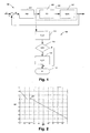
- a closed loop control system 100 is illustrated.
- the system comprises a PID controller 101 receiving the control error e as input, where the control error has been calculated by subtracting the process output from a reference r. Based on the control error, the PID controller calculates a controller output given to the system 103 as control input.
- the control input is given to a control unit (CU) 105 from which the system can be influenced, e.g. an actuator for a valve or the like.
- the control unit responds to the control input and influences the process Gp(s). If the control unit is an actuator for a valve, it responds by changing how open or closed the valve is.
- the control input is being processed as illustrated in the flow diagram 109.
- the control input is low pass filtered in 111 (F CI), then in 113 (OSC) it is detected whether there are oscillations in the control input. If oscillations are present, then in 115 the control input is amplified (A CI) with a multiplication factor typically less than 1 in order to dampen the control input to the control unit. If no oscillations are detected, the algorithm is ended in 117 (E).
- the algorithm as described could be performed each time the general control program for controlling the process is executed, e.g. each time, whereby oscillations are detected as they occur as an integrated part of determining the control input to the control unit.
- the degree of oscillations is determined and used for determining the value of the multiplication factor.
- Decay ratio DR peak ⁇ 1 - peak ⁇ 2 / peak ⁇ 3 - peak ⁇ 4 , where peak1 is the last peak and peak 4 is the first detected peak.
- FIG 2 an example of dependency between calculated decay ratio DR and multiplication factor MF is illustrated.
- the range from 0.15 to 0.25 is chosen 201, and if the measured decay ratio DR is in this range, the multiplication factor is 1 and the control input will not be changed.
- the damping of the control input is too high, and the multiplication factor is more than 1 in order to increase control input to the control unit.
- the decay ratio is getting smaller than 0.15, the multiplication factor is linearly increasing.
- the damping of the control input is too low, and the multiplication factor is less than 1 in order to decrease control input to the control unit.
- the multiplication factor is linearly decreasing.
- interval 0.15 - 0.25 is just an example where tests have shown successful results (good tracking and disturbance rejection properties), but other intervals having another size and position could be chosen depending on the control system and the characteristics of the control unit.
- the multiplication factor needs not be linearly decreasing and increasing around the interval - the main importance is that oscillations are damped via a multiplication factor less than 1, and too much damping is amplified via a multiplication factor more than 1.
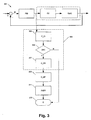
- a control loop is illustrated 301 similar to the one in figure 1 and where further steps are comprised in the method of controlling.
- the oscillation detection is performed in 304 and consists of the control input being low pass filtered in 303 (F_CI) in order to remove high frequency noise. Further in 305 (OSC) it is detected whether there are oscillations in the control input. If oscillations are present, then in 307 the decay ratio is calculated (C_DR) as described above.
- the algorithm is ended in 313 (E).
- the algorithm as described could be performed each time the general control program for controlling the process is executed, e.g. each time, whereby oscillations are detected as they occur as an integrated part of determining the control input to the control unit.
- FIG 4 an example is given of the step 311 in figure 3 where the control unit is a valve.
- the working range of the valve is represented with three points 401, 403, 405 - these points represent amplification of the valve at 0%, 50% and 100% openness of the valve. Amplification can never be higher or lower than preset value (parameter gain_max (e.g. value 1) and gain_min (eg. value 0.2)). Further, the value of amplification in the range 0% to 50% and in the range 50% to 100% is determined by interpolating the three points representing the working range.
- control according to the present invention is that if calculations show that a reduction of the amplification of a factor 0.5 is needed, then amplification is reduced in all three points, but not in the same degree for all points. Amplification is reduced most in the point nearest the point where the oscillations appeared and least in the point most distant to the point of the oscillation. Algorithms for calculating the reductions for each point could in an embodiment be algorithms similar to the ones used in fuzzy control systems.
- FIG 5 the change of the amplification in the three working points is illustrated, where after oscillations have been detected near 40% of openness of the valve. Amplification is reduced by suitably changing the three points representing the working range. Most changed is the point near the range where oscillations appeared (50%) and the least changed point is the most distant point (100%). The working range after this change is then represented with three points 501, 503, 505. These points represent amplification of the valve at 0%, 50% and 100% openness of valve. Again the value of amplification in the range 0% to 50% and in the range 50% to 100% is determined by interpolating the three points representing the working range.
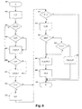
- the oscillation detector illustrated as 304 in figure 3 .
- the algorithm is started.
- the input signal is filtered (F_CI) and in 604 it is determined whether the routine shall search for a negative or a positive peak (S_P_P), this depends on which peak where detected previously and if it is the first iteration the algorithm starts searching for a positive peak.
- the routine could also start by searching for a negative peak.
- P_P a positive peak is confirmed if the signal is less than a maximum detected value minus hysteresis
- the peak is counted in 607 by adding to a counter a new positive peak (A_N_P_P).
- N_P a negative peak is confirmed if the signal is more than a minimum detected value plus hysteresis
- the negative peak is counted in 611 by adding to a counter a new negative peak (A_N_N_P).
Claims (9)
- Verfahren zum Regeln eines Regelsystems (103), das von einer Regelvorrichtung (101) geregelt wird, wobei die Regelvorrichtung (101) den Regeleingang zu mindestens einer Regeleinheit (105) in dem System, z. B. einem Ventil, liefert, wobei das Verfahren folgende Schritte umfasst:- Detektieren des Oszillationspegels (113) in dem Regeleingang in die Regeleinheit,- Verstärken (115) des Regeleingangs um einen Multiplikationsfaktor auf der Basis des detektierten Oszillationspegels,dadurch gekennzeichnet, dass
der Oszillationspegel durch Berechnen eines Ausschwingverhältnisses auf der Basis detektierter Spitzen detektiert wird und wobei das Ausschwingverhältnis zum Ermitteln des Multiplikationsfaktors verwendet wird und wobei der verstärkte (115) Regeleingang als Regeleingang in die mindestens eine Regeleinheit (105) verwendet wird. - Verfahren nach Anspruch 1, wobei ein Bereich von Ausschwingverhältnissen als optimaler Ausschwingverhältnisbereich (201) gewählt wird, was zu einem Multiplikationsfaktor von 1 führt, und wobei ein Ausschwingverhältnis, das kleiner ist als der optimale Ausschwingverhältnisbereich (201), zu einem Multiplikationsfaktor von größer als 1 in einer sich vergrößernden Beziehung zu einem sich verkleinernden Multiplikationsfaktor führt und ein Ausschwingverhältnis, das größer ist als der optimale Ausschwingverhältnisbereich (201) zu einem Multiplikationsfaktor von kleiner als 1 in einer sich verkleinernden Beziehung zu einem sich vergrößernden Multiplikationsfaktor führt.
- Verfahren nach Anspruch 2, wobei sich die Beziehung in Bezug auf den Multiplikationsfaktor linear vergrößert und verkleinert.
- Verfahren nach Anspruch 2 oder 3, wobei der optimale Ausschwingverhältnisbereich (201) das Intervall von 0,15-0,25 ist.
- Verfahren nach einem der Ansprüche 1-4, wobei das Verfahren ferner den Schritt des Ermittelns der Verstärkung des Regeleingangs für den gesamten Arbeitsbereich der Regeleinheit umfasst und wobei das Verfahren die folgenden Schritte umfasst:- Ermitteln des Verstärkungswerts für mindestens drei vordefinierte Arbeitspunkte, die den gesamten Arbeitsbereich darstellen,- Interpolieren der Verstärkungswerte für die Werte der Verstärkung in den Arbeitsbereichen zwischen den mindestens drei vordefinierten Arbeitspunkten.
- Verfahren nach Anspruch 5, wobei die Verstärkung in dem Punkt am stärksten verringert wird, an dem die Oszillationen aufgetreten sind, und am wenigsten in dem Punkt, der von dem Punkt der Oszillation am weitesten entfernt ist.
- Verfahren nach einem der Ansprüche 1-6, wobei die Verstärkung des Regeleingangs zwischen einer maximalen und einer minimalen voreingestellten Verstärkung liegen muss.
- Regelsystem (100, 301), das eine Regeleinheit (105), z. B. ein Stellglied, wie z. B. ein Ventil, umfasst, welches so ausgelegt ist, dass es als Teil eines Systems verwendet wird, das in einem Regelsystem (103) von einer Regelvorrichtung (101) geregelt wird, wobei die Regelvorrichtung (101) den Regeleingang zu der Regeleinheit (105) liefert, wobei die Einheit umfasst:- eine Einrichtung (109, 113) zum Detektieren des Oszillationspegels in dem Regeleingang aus der Regelvorrichtung (101) durch Berechnen eines Ausschwingverhältnisses auf der Basis von detektierten Spitzen und wobei das Ausschwingverhältnis zum Ermitteln des Multiplikationsfaktors verwendet wird,- eine Einrichtung zum Verstärken (109, 115) des Regeleingangs um den Multiplikationsfaktor auf der Basis des detektierten Oszillationspegels,und wobei der verstärkte (115) Regeleingang als Regeleingang in die Regeleinheit (105) verwendet wird.
- Regelsystem (100, 301) nach Anspruch 8, wobei das Regelsystem (100, 301) so ausgelegt ist, dass es anhand des Verfahrens nach einem der Ansprüche 1-7 arbeitet.
Priority Applications (2)
| Application Number | Priority Date | Filing Date | Title |
|---|---|---|---|
| SI200931366T SI2356522T1 (sl) | 2008-11-17 | 2009-11-16 | Zmanjševanje oscilacij v kontrolnem sistemu |
| PL09756409T PL2356522T3 (pl) | 2008-11-17 | 2009-11-16 | Zmniejszenie oscylacji w układzie sterowania |
Applications Claiming Priority (2)
| Application Number | Priority Date | Filing Date | Title |
|---|---|---|---|
| DKPA200801591 | 2008-11-17 | ||
| PCT/DK2009/000236 WO2010054657A1 (en) | 2008-11-17 | 2009-11-16 | Reducing oscillations in a control system |
Publications (2)
| Publication Number | Publication Date |
|---|---|
| EP2356522A1 EP2356522A1 (de) | 2011-08-17 |
| EP2356522B1 true EP2356522B1 (de) | 2016-01-06 |
Family
ID=41650304
Family Applications (1)
| Application Number | Title | Priority Date | Filing Date |
|---|---|---|---|
| EP09756409.0A Active EP2356522B1 (de) | 2008-11-17 | 2009-11-16 | Verringerung von oszillationen in einem regelsystem |
Country Status (7)
| Country | Link |
|---|---|
| EP (1) | EP2356522B1 (de) |
| CN (2) | CN105717910A (de) |
| DK (1) | DK2356522T3 (de) |
| PL (1) | PL2356522T3 (de) |
| RU (1) | RU2494431C2 (de) |
| SI (1) | SI2356522T1 (de) |
| WO (1) | WO2010054657A1 (de) |
Cited By (1)
| Publication number | Priority date | Publication date | Assignee | Title |
|---|---|---|---|---|
| DE102022107930A1 (de) | 2022-04-04 | 2023-10-05 | Festo Se & Co. Kg | Reglereinrichtung, Reglergerät und Verfahren |
Families Citing this family (4)
| Publication number | Priority date | Publication date | Assignee | Title |
|---|---|---|---|---|
| DE102018203574A1 (de) | 2018-03-09 | 2019-09-12 | Robert Bosch Gmbh | Verfahren zur Bestimmung von in einem Messsignal vorkommenden Schwingungen |
| EP3543803A1 (de) * | 2018-03-22 | 2019-09-25 | Metro Therm A/S | Verfahren zur steuerung eines heizsystems und solch ein heizsystem |
| US10855079B1 (en) | 2019-07-19 | 2020-12-01 | General Electric Company | System and method for reducing oscillations in a renewable energy power system |
| DE102022114745B3 (de) * | 2022-06-10 | 2023-07-20 | Samson Aktiengesellschaft | Verhindern von regelungsbedingten Schwingungen der Position eines Ventilglieds bei einem Ventil mit pneumatischem Antrieb |
Family Cites Families (8)
| Publication number | Priority date | Publication date | Assignee | Title |
|---|---|---|---|---|
| GB1190580A (en) * | 1966-08-16 | 1970-05-06 | Ici Ltd | Gain-Adaptive Control. |
| SE320432B (de) * | 1966-11-29 | 1970-02-09 | Asea Ab | |
| RU2068196C1 (ru) * | 1992-12-07 | 1996-10-20 | Акционерное общество закрытого типа "Экспериментальная лаборатория системотехники" | Самонастраивающаяся система управления |
| EP1441266B1 (de) * | 1997-07-23 | 2007-03-21 | Dresser, Inc. | Ventilpositioniersystem |
| RU2130635C1 (ru) * | 1998-03-30 | 1999-05-20 | Иркутское высшее военное авиационное инженерное училище | Адаптивная система управления с переменной структурой |
| JP3875458B2 (ja) * | 2000-06-30 | 2007-01-31 | 株式会社東芝 | 送受信一体型高周波装置 |
| US6970750B2 (en) * | 2001-07-13 | 2005-11-29 | Fisher-Rosemount Systems, Inc. | Model-free adaptation of a process controller |
| US6937909B2 (en) * | 2003-07-02 | 2005-08-30 | Johnson Controls Technology Company | Pattern recognition adaptive controller |
-
2009
- 2009-11-16 CN CN201610027372.2A patent/CN105717910A/zh active Pending
- 2009-11-16 PL PL09756409T patent/PL2356522T3/pl unknown
- 2009-11-16 WO PCT/DK2009/000236 patent/WO2010054657A1/en active Application Filing
- 2009-11-16 CN CN2009801459341A patent/CN102257444A/zh active Pending
- 2009-11-16 EP EP09756409.0A patent/EP2356522B1/de active Active
- 2009-11-16 DK DK09756409.0T patent/DK2356522T3/en active
- 2009-11-16 RU RU2011124177/08A patent/RU2494431C2/ru active
- 2009-11-16 SI SI200931366T patent/SI2356522T1/sl unknown
Cited By (2)
| Publication number | Priority date | Publication date | Assignee | Title |
|---|---|---|---|---|
| DE102022107930A1 (de) | 2022-04-04 | 2023-10-05 | Festo Se & Co. Kg | Reglereinrichtung, Reglergerät und Verfahren |
| WO2023194306A1 (de) | 2022-04-04 | 2023-10-12 | Festo Se & Co. Kg | Reglereinrichtung, reglergerät und verfahren |
Also Published As
| Publication number | Publication date |
|---|---|
| RU2494431C2 (ru) | 2013-09-27 |
| EP2356522A1 (de) | 2011-08-17 |
| CN102257444A (zh) | 2011-11-23 |
| RU2011124177A (ru) | 2012-12-27 |
| DK2356522T3 (en) | 2016-04-11 |
| CN105717910A (zh) | 2016-06-29 |
| SI2356522T1 (sl) | 2016-04-29 |
| PL2356522T3 (pl) | 2016-06-30 |
| WO2010054657A1 (en) | 2010-05-20 |
Similar Documents
| Publication | Publication Date | Title |
|---|---|---|
| EP2356522B1 (de) | Verringerung von oszillationen in einem regelsystem | |
| US9423786B2 (en) | Motor drive device | |
| EP3641127B1 (de) | Elektromotorsteuerungsvorrichtung und elektromotorsteuerungsvorrichtungsteuerungsverfahren | |
| Veronesi et al. | Simultaneous closed-loop automatic tuning method for cascade controllers | |
| US8975849B2 (en) | Motor control apparatus | |
| CN1867965B (zh) | 使用自适应噪声基底跟踪的语音活动检测 | |
| US6580245B2 (en) | Jerk-limitation with adaptation of the path dynamics | |
| CN106909073B (zh) | 一种数字调节器的参数调整方法 | |
| JP6304461B1 (ja) | モータ制御装置 | |
| US20130090747A1 (en) | Closed-Loop Control Device | |
| Rossiter et al. | Modelling and implicit modelling for predictive control | |
| US9733641B2 (en) | Method and apparatus for performing diagnostics on a conventional control valve | |
| GB2400191A (en) | Control system for quantity having characteristic frequency behaviour | |
| KR101708739B1 (ko) | 복수개의 고정 노치 필터를 이용한 서보 시스템의 공진 감지 및 억제 장치 및 그 방법 | |
| US8295954B2 (en) | Method and device for adjusting a regulating device | |
| CN111168196B (zh) | 爬行焊接机器人的控制方法、机器人及存储介质 | |
| KR102278353B1 (ko) | 서보 시스템의 자동 공진 검출 및 억제 장치 및 그 방법 | |
| US7797129B2 (en) | Processing data to maintain an estimate of a running median | |
| Kurien et al. | Overview of different approaches of pid controller tuning | |
| JP3336520B2 (ja) | Pid調節計 | |
| JP2008102743A (ja) | オートチューニング装置およびオートチューニング方法 | |
| KR101234549B1 (ko) | 범용성을 가지는 원자로 출력제어방법 및 원자로 출력제어시스템 | |
| JP2021189514A (ja) | マスフローコントローラおよびハンチング抑制方法 | |
| KR101572241B1 (ko) | 강건한 제어 성능을 갖는 제어시스템 | |
| US6847851B1 (en) | Apparatus for improved general-purpose PID and non-PID controllers |
Legal Events
| Date | Code | Title | Description |
|---|---|---|---|
| PUAI | Public reference made under article 153(3) epc to a published international application that has entered the european phase |
Free format text: ORIGINAL CODE: 0009012 |
|
| 17P | Request for examination filed |
Effective date: 20110610 |
|
| AK | Designated contracting states |
Kind code of ref document: A1 Designated state(s): AT BE BG CH CY CZ DE DK EE ES FI FR GB GR HR HU IE IS IT LI LT LU LV MC MK MT NL NO PL PT RO SE SI SK SM TR |
|
| DAX | Request for extension of the european patent (deleted) | ||
| 17Q | First examination report despatched |
Effective date: 20121128 |
|
| GRAP | Despatch of communication of intention to grant a patent |
Free format text: ORIGINAL CODE: EPIDOSNIGR1 |
|
| INTG | Intention to grant announced |
Effective date: 20150708 |
|
| GRAS | Grant fee paid |
Free format text: ORIGINAL CODE: EPIDOSNIGR3 |
|
| GRAA | (expected) grant |
Free format text: ORIGINAL CODE: 0009210 |
|
| AK | Designated contracting states |
Kind code of ref document: B1 Designated state(s): AT BE BG CH CY CZ DE DK EE ES FI FR GB GR HR HU IE IS IT LI LT LU LV MC MK MT NL NO PL PT RO SE SI SK SM TR |
|
| REG | Reference to a national code |
Ref country code: GB Ref legal event code: FG4D |
|
| REG | Reference to a national code |
Ref country code: CH Ref legal event code: EP |
|
| REG | Reference to a national code |
Ref country code: IE Ref legal event code: FG4D |
|
| REG | Reference to a national code |
Ref country code: AT Ref legal event code: REF Ref document number: 769361 Country of ref document: AT Kind code of ref document: T Effective date: 20160215 |
|
| REG | Reference to a national code |
Ref country code: DE Ref legal event code: R096 Ref document number: 602009035634 Country of ref document: DE |
|
| REG | Reference to a national code |
Ref country code: SE Ref legal event code: TRGR |
|
| REG | Reference to a national code |
Ref country code: NL Ref legal event code: FP |
|
| REG | Reference to a national code |
Ref country code: RO Ref legal event code: EPE |
|
| REG | Reference to a national code |
Ref country code: DK Ref legal event code: T3 Effective date: 20160407 |
|
| REG | Reference to a national code |
Ref country code: LT Ref legal event code: MG4D |
|
| PG25 | Lapsed in a contracting state [announced via postgrant information from national office to epo] |
Ref country code: GR Free format text: LAPSE BECAUSE OF FAILURE TO SUBMIT A TRANSLATION OF THE DESCRIPTION OR TO PAY THE FEE WITHIN THE PRESCRIBED TIME-LIMIT Effective date: 20160407 Ref country code: HR Free format text: LAPSE BECAUSE OF FAILURE TO SUBMIT A TRANSLATION OF THE DESCRIPTION OR TO PAY THE FEE WITHIN THE PRESCRIBED TIME-LIMIT Effective date: 20160106 Ref country code: FI Free format text: LAPSE BECAUSE OF FAILURE TO SUBMIT A TRANSLATION OF THE DESCRIPTION OR TO PAY THE FEE WITHIN THE PRESCRIBED TIME-LIMIT Effective date: 20160106 Ref country code: ES Free format text: LAPSE BECAUSE OF FAILURE TO SUBMIT A TRANSLATION OF THE DESCRIPTION OR TO PAY THE FEE WITHIN THE PRESCRIBED TIME-LIMIT Effective date: 20160106 Ref country code: NO Free format text: LAPSE BECAUSE OF FAILURE TO SUBMIT A TRANSLATION OF THE DESCRIPTION OR TO PAY THE FEE WITHIN THE PRESCRIBED TIME-LIMIT Effective date: 20160406 |
|
| PG25 | Lapsed in a contracting state [announced via postgrant information from national office to epo] |
Ref country code: IS Free format text: LAPSE BECAUSE OF FAILURE TO SUBMIT A TRANSLATION OF THE DESCRIPTION OR TO PAY THE FEE WITHIN THE PRESCRIBED TIME-LIMIT Effective date: 20160506 Ref country code: PT Free format text: LAPSE BECAUSE OF FAILURE TO SUBMIT A TRANSLATION OF THE DESCRIPTION OR TO PAY THE FEE WITHIN THE PRESCRIBED TIME-LIMIT Effective date: 20160506 Ref country code: LV Free format text: LAPSE BECAUSE OF FAILURE TO SUBMIT A TRANSLATION OF THE DESCRIPTION OR TO PAY THE FEE WITHIN THE PRESCRIBED TIME-LIMIT Effective date: 20160106 Ref country code: LT Free format text: LAPSE BECAUSE OF FAILURE TO SUBMIT A TRANSLATION OF THE DESCRIPTION OR TO PAY THE FEE WITHIN THE PRESCRIBED TIME-LIMIT Effective date: 20160106 |
|
| REG | Reference to a national code |
Ref country code: DE Ref legal event code: R097 Ref document number: 602009035634 Country of ref document: DE |
|
| PG25 | Lapsed in a contracting state [announced via postgrant information from national office to epo] |
Ref country code: EE Free format text: LAPSE BECAUSE OF FAILURE TO SUBMIT A TRANSLATION OF THE DESCRIPTION OR TO PAY THE FEE WITHIN THE PRESCRIBED TIME-LIMIT Effective date: 20160106 |
|
| PLBE | No opposition filed within time limit |
Free format text: ORIGINAL CODE: 0009261 |
|
| STAA | Information on the status of an ep patent application or granted ep patent |
Free format text: STATUS: NO OPPOSITION FILED WITHIN TIME LIMIT |
|
| PG25 | Lapsed in a contracting state [announced via postgrant information from national office to epo] |
Ref country code: SK Free format text: LAPSE BECAUSE OF FAILURE TO SUBMIT A TRANSLATION OF THE DESCRIPTION OR TO PAY THE FEE WITHIN THE PRESCRIBED TIME-LIMIT Effective date: 20160106 Ref country code: SM Free format text: LAPSE BECAUSE OF FAILURE TO SUBMIT A TRANSLATION OF THE DESCRIPTION OR TO PAY THE FEE WITHIN THE PRESCRIBED TIME-LIMIT Effective date: 20160106 Ref country code: CZ Free format text: LAPSE BECAUSE OF FAILURE TO SUBMIT A TRANSLATION OF THE DESCRIPTION OR TO PAY THE FEE WITHIN THE PRESCRIBED TIME-LIMIT Effective date: 20160106 |
|
| 26N | No opposition filed |
Effective date: 20161007 |
|
| PG25 | Lapsed in a contracting state [announced via postgrant information from national office to epo] |
Ref country code: BE Free format text: LAPSE BECAUSE OF FAILURE TO SUBMIT A TRANSLATION OF THE DESCRIPTION OR TO PAY THE FEE WITHIN THE PRESCRIBED TIME-LIMIT Effective date: 20160106 |
|
| PG25 | Lapsed in a contracting state [announced via postgrant information from national office to epo] |
Ref country code: BG Free format text: LAPSE BECAUSE OF FAILURE TO SUBMIT A TRANSLATION OF THE DESCRIPTION OR TO PAY THE FEE WITHIN THE PRESCRIBED TIME-LIMIT Effective date: 20160406 |
|
| REG | Reference to a national code |
Ref country code: CH Ref legal event code: PL |
|
| PG25 | Lapsed in a contracting state [announced via postgrant information from national office to epo] |
Ref country code: LI Free format text: LAPSE BECAUSE OF NON-PAYMENT OF DUE FEES Effective date: 20161130 Ref country code: CH Free format text: LAPSE BECAUSE OF NON-PAYMENT OF DUE FEES Effective date: 20161130 |
|
| REG | Reference to a national code |
Ref country code: IE Ref legal event code: MM4A |
|
| REG | Reference to a national code |
Ref country code: FR Ref legal event code: ST Effective date: 20170731 |
|
| PG25 | Lapsed in a contracting state [announced via postgrant information from national office to epo] |
Ref country code: LU Free format text: LAPSE BECAUSE OF NON-PAYMENT OF DUE FEES Effective date: 20161130 |
|
| PG25 | Lapsed in a contracting state [announced via postgrant information from national office to epo] |
Ref country code: FR Free format text: LAPSE BECAUSE OF NON-PAYMENT OF DUE FEES Effective date: 20161130 |
|
| PG25 | Lapsed in a contracting state [announced via postgrant information from national office to epo] |
Ref country code: IE Free format text: LAPSE BECAUSE OF NON-PAYMENT OF DUE FEES Effective date: 20161116 |
|
| REG | Reference to a national code |
Ref country code: AT Ref legal event code: UEP Ref document number: 769361 Country of ref document: AT Kind code of ref document: T Effective date: 20160106 |
|
| PG25 | Lapsed in a contracting state [announced via postgrant information from national office to epo] |
Ref country code: CY Free format text: LAPSE BECAUSE OF FAILURE TO SUBMIT A TRANSLATION OF THE DESCRIPTION OR TO PAY THE FEE WITHIN THE PRESCRIBED TIME-LIMIT Effective date: 20160106 Ref country code: HU Free format text: LAPSE BECAUSE OF FAILURE TO SUBMIT A TRANSLATION OF THE DESCRIPTION OR TO PAY THE FEE WITHIN THE PRESCRIBED TIME-LIMIT; INVALID AB INITIO Effective date: 20091116 |
|
| PG25 | Lapsed in a contracting state [announced via postgrant information from national office to epo] |
Ref country code: MC Free format text: LAPSE BECAUSE OF FAILURE TO SUBMIT A TRANSLATION OF THE DESCRIPTION OR TO PAY THE FEE WITHIN THE PRESCRIBED TIME-LIMIT Effective date: 20160106 Ref country code: MK Free format text: LAPSE BECAUSE OF FAILURE TO SUBMIT A TRANSLATION OF THE DESCRIPTION OR TO PAY THE FEE WITHIN THE PRESCRIBED TIME-LIMIT Effective date: 20160106 |
|
| PG25 | Lapsed in a contracting state [announced via postgrant information from national office to epo] |
Ref country code: MT Free format text: LAPSE BECAUSE OF NON-PAYMENT OF DUE FEES Effective date: 20161116 |
|
| REG | Reference to a national code |
Ref country code: DE Ref legal event code: R082 Ref document number: 602009035634 Country of ref document: DE Representative=s name: KILBURN & STRODE LLP, NL |
|
| PGFP | Annual fee paid to national office [announced via postgrant information from national office to epo] |
Ref country code: DK Payment date: 20221111 Year of fee payment: 14 |
|
| P01 | Opt-out of the competence of the unified patent court (upc) registered |
Effective date: 20230617 |
|
| PGFP | Annual fee paid to national office [announced via postgrant information from national office to epo] |
Ref country code: NL Payment date: 20231013 Year of fee payment: 15 |
|
| PGFP | Annual fee paid to national office [announced via postgrant information from national office to epo] |
Ref country code: GB Payment date: 20231006 Year of fee payment: 15 |
|
| PGFP | Annual fee paid to national office [announced via postgrant information from national office to epo] |
Ref country code: TR Payment date: 20231115 Year of fee payment: 15 Ref country code: SI Payment date: 20231016 Year of fee payment: 15 Ref country code: SE Payment date: 20231010 Year of fee payment: 15 Ref country code: RO Payment date: 20231013 Year of fee payment: 15 Ref country code: IT Payment date: 20231010 Year of fee payment: 15 Ref country code: DE Payment date: 20231003 Year of fee payment: 15 Ref country code: AT Payment date: 20231025 Year of fee payment: 15 |
|
| PGFP | Annual fee paid to national office [announced via postgrant information from national office to epo] |
Ref country code: PL Payment date: 20231016 Year of fee payment: 15 |