EP2354718A2 - Integrationsblock für Solarmodul und mit solchen Blocks versehenes Dach - Google Patents
Integrationsblock für Solarmodul und mit solchen Blocks versehenes Dach Download PDFInfo
- Publication number
- EP2354718A2 EP2354718A2 EP10164176A EP10164176A EP2354718A2 EP 2354718 A2 EP2354718 A2 EP 2354718A2 EP 10164176 A EP10164176 A EP 10164176A EP 10164176 A EP10164176 A EP 10164176A EP 2354718 A2 EP2354718 A2 EP 2354718A2
- Authority
- EP
- European Patent Office
- Prior art keywords
- frame
- solar energy
- profile
- recess
- energy module
- Prior art date
- Legal status (The legal status is an assumption and is not a legal conclusion. Google has not performed a legal analysis and makes no representation as to the accuracy of the status listed.)
- Withdrawn
Links
- 230000010354 integration Effects 0.000 title claims abstract description 41
- 230000037431 insertion Effects 0.000 claims abstract description 6
- 238000003780 insertion Methods 0.000 claims abstract description 6
- 230000000295 complement effect Effects 0.000 claims abstract description 4
- 238000007789 sealing Methods 0.000 claims description 7
- 230000008595 infiltration Effects 0.000 description 5
- 238000001764 infiltration Methods 0.000 description 5
- 238000009434 installation Methods 0.000 description 5
- 239000008393 encapsulating agent Substances 0.000 description 2
- 239000000463 material Substances 0.000 description 2
- XAGFODPZIPBFFR-UHFFFAOYSA-N aluminium Chemical compound [Al] XAGFODPZIPBFFR-UHFFFAOYSA-N 0.000 description 1
- 229910052782 aluminium Inorganic materials 0.000 description 1
- 238000005352 clarification Methods 0.000 description 1
- 238000010586 diagram Methods 0.000 description 1
- 229920003023 plastic Polymers 0.000 description 1
- 229920002620 polyvinyl fluoride Polymers 0.000 description 1
- 238000010248 power generation Methods 0.000 description 1
- 229920002379 silicone rubber Polymers 0.000 description 1
- 239000004945 silicone rubber Substances 0.000 description 1
- 239000013589 supplement Substances 0.000 description 1
- 239000005341 toughened glass Substances 0.000 description 1
- XLYOFNOQVPJJNP-UHFFFAOYSA-N water Substances O XLYOFNOQVPJJNP-UHFFFAOYSA-N 0.000 description 1
Images

Classifications
-
- H—ELECTRICITY
- H02—GENERATION; CONVERSION OR DISTRIBUTION OF ELECTRIC POWER
- H02S—GENERATION OF ELECTRIC POWER BY CONVERSION OF INFRARED RADIATION, VISIBLE LIGHT OR ULTRAVIOLET LIGHT, e.g. USING PHOTOVOLTAIC [PV] MODULES
- H02S20/00—Supporting structures for PV modules
- H02S20/20—Supporting structures directly fixed to an immovable object
- H02S20/22—Supporting structures directly fixed to an immovable object specially adapted for buildings
- H02S20/23—Supporting structures directly fixed to an immovable object specially adapted for buildings specially adapted for roof structures
-
- F—MECHANICAL ENGINEERING; LIGHTING; HEATING; WEAPONS; BLASTING
- F24—HEATING; RANGES; VENTILATING
- F24S—SOLAR HEAT COLLECTORS; SOLAR HEAT SYSTEMS
- F24S25/00—Arrangement of stationary mountings or supports for solar heat collector modules
- F24S25/20—Peripheral frames for modules
-
- F—MECHANICAL ENGINEERING; LIGHTING; HEATING; WEAPONS; BLASTING
- F24—HEATING; RANGES; VENTILATING
- F24S—SOLAR HEAT COLLECTORS; SOLAR HEAT SYSTEMS
- F24S25/00—Arrangement of stationary mountings or supports for solar heat collector modules
- F24S25/60—Fixation means, e.g. fasteners, specially adapted for supporting solar heat collector modules
- F24S25/67—Fixation means, e.g. fasteners, specially adapted for supporting solar heat collector modules for coupling adjacent modules or their peripheral frames
-
- H—ELECTRICITY
- H02—GENERATION; CONVERSION OR DISTRIBUTION OF ELECTRIC POWER
- H02S—GENERATION OF ELECTRIC POWER BY CONVERSION OF INFRARED RADIATION, VISIBLE LIGHT OR ULTRAVIOLET LIGHT, e.g. USING PHOTOVOLTAIC [PV] MODULES
- H02S30/00—Structural details of PV modules other than those related to light conversion
- H02S30/10—Frame structures
-
- F—MECHANICAL ENGINEERING; LIGHTING; HEATING; WEAPONS; BLASTING
- F24—HEATING; RANGES; VENTILATING
- F24S—SOLAR HEAT COLLECTORS; SOLAR HEAT SYSTEMS
- F24S20/00—Solar heat collectors specially adapted for particular uses or environments
- F24S2020/10—Solar modules layout; Modular arrangements
- F24S2020/12—Coplanar arrangements with frame overlapping portions
-
- F—MECHANICAL ENGINEERING; LIGHTING; HEATING; WEAPONS; BLASTING
- F24—HEATING; RANGES; VENTILATING
- F24S—SOLAR HEAT COLLECTORS; SOLAR HEAT SYSTEMS
- F24S25/00—Arrangement of stationary mountings or supports for solar heat collector modules
- F24S2025/01—Special support components; Methods of use
- F24S2025/021—Sealing means between support elements and mounting surface
-
- F—MECHANICAL ENGINEERING; LIGHTING; HEATING; WEAPONS; BLASTING
- F24—HEATING; RANGES; VENTILATING
- F24S—SOLAR HEAT COLLECTORS; SOLAR HEAT SYSTEMS
- F24S25/00—Arrangement of stationary mountings or supports for solar heat collector modules
- F24S25/60—Fixation means, e.g. fasteners, specially adapted for supporting solar heat collector modules
- F24S2025/6012—Joining different materials
-
- Y—GENERAL TAGGING OF NEW TECHNOLOGICAL DEVELOPMENTS; GENERAL TAGGING OF CROSS-SECTIONAL TECHNOLOGIES SPANNING OVER SEVERAL SECTIONS OF THE IPC; TECHNICAL SUBJECTS COVERED BY FORMER USPC CROSS-REFERENCE ART COLLECTIONS [XRACs] AND DIGESTS
- Y02—TECHNOLOGIES OR APPLICATIONS FOR MITIGATION OR ADAPTATION AGAINST CLIMATE CHANGE
- Y02B—CLIMATE CHANGE MITIGATION TECHNOLOGIES RELATED TO BUILDINGS, e.g. HOUSING, HOUSE APPLIANCES OR RELATED END-USER APPLICATIONS
- Y02B10/00—Integration of renewable energy sources in buildings
- Y02B10/10—Photovoltaic [PV]
-
- Y—GENERAL TAGGING OF NEW TECHNOLOGICAL DEVELOPMENTS; GENERAL TAGGING OF CROSS-SECTIONAL TECHNOLOGIES SPANNING OVER SEVERAL SECTIONS OF THE IPC; TECHNICAL SUBJECTS COVERED BY FORMER USPC CROSS-REFERENCE ART COLLECTIONS [XRACs] AND DIGESTS
- Y02—TECHNOLOGIES OR APPLICATIONS FOR MITIGATION OR ADAPTATION AGAINST CLIMATE CHANGE
- Y02B—CLIMATE CHANGE MITIGATION TECHNOLOGIES RELATED TO BUILDINGS, e.g. HOUSING, HOUSE APPLIANCES OR RELATED END-USER APPLICATIONS
- Y02B10/00—Integration of renewable energy sources in buildings
- Y02B10/20—Solar thermal
-
- Y—GENERAL TAGGING OF NEW TECHNOLOGICAL DEVELOPMENTS; GENERAL TAGGING OF CROSS-SECTIONAL TECHNOLOGIES SPANNING OVER SEVERAL SECTIONS OF THE IPC; TECHNICAL SUBJECTS COVERED BY FORMER USPC CROSS-REFERENCE ART COLLECTIONS [XRACs] AND DIGESTS
- Y02—TECHNOLOGIES OR APPLICATIONS FOR MITIGATION OR ADAPTATION AGAINST CLIMATE CHANGE
- Y02E—REDUCTION OF GREENHOUSE GAS [GHG] EMISSIONS, RELATED TO ENERGY GENERATION, TRANSMISSION OR DISTRIBUTION
- Y02E10/00—Energy generation through renewable energy sources
- Y02E10/40—Solar thermal energy, e.g. solar towers
- Y02E10/47—Mountings or tracking
-
- Y—GENERAL TAGGING OF NEW TECHNOLOGICAL DEVELOPMENTS; GENERAL TAGGING OF CROSS-SECTIONAL TECHNOLOGIES SPANNING OVER SEVERAL SECTIONS OF THE IPC; TECHNICAL SUBJECTS COVERED BY FORMER USPC CROSS-REFERENCE ART COLLECTIONS [XRACs] AND DIGESTS
- Y02—TECHNOLOGIES OR APPLICATIONS FOR MITIGATION OR ADAPTATION AGAINST CLIMATE CHANGE
- Y02E—REDUCTION OF GREENHOUSE GAS [GHG] EMISSIONS, RELATED TO ENERGY GENERATION, TRANSMISSION OR DISTRIBUTION
- Y02E10/00—Energy generation through renewable energy sources
- Y02E10/50—Photovoltaic [PV] energy
Definitions
- the present patent relates to an integration block for solar energy modules and in particular the structure of the assembly components of such a block, as well as the roof comprising these integration blocks.
- a photovoltaic power generation system comprises a plurality of solar energy modules, which modules include components that convert solar energy into electrical energy and assembly components, among which assembly components including a profile for the front frame, a profile for the rear frame and two profiles for the lateral uprights of the frame, together forming a rectangular frame.
- the cross sections of the various sections of the traditional joining components are generally L-shaped and once assembled together, all their faces viewed from the outside are planar.
- solar energy modules are installed on roofs that are suitably exposed to the sun. When installing the modules on the roof, you must first install a waterproof layer, then use a large amount of hardware to attach a frame to the roof and finally attach the solar energy modules to the chassis. Not only is the implementation of this type of site tedious, but in case of rain, the water that infiltrates between the modules may eventually penetrate into the piercing holes of the roof and thereby create infiltrations to the inside of the rooms.
- This patent solves certain technical problems encountered in installing solar energy modules by providing simpler mounting solutions, which at the same time improve the overall impermeability.
- an upper surface of the mounting slide of the front frame profile and the upper surface of said front recess will be on the same plane; likewise an upper surface of the mounting slide of said rear frame profile and an upper surface of said rear recess will be on the same plane.
- a roof comprising a plurality of aforementioned integration blocks for a solar energy module.
- the rear recesses of the rear frame sections of the integration blocks fit by recess in the recesses before the front frame profiles of said neighboring integration blocks; the two sections of the lateral frame uprights of two so-called neighboring integration blocks being joined together by a fixing profile and screws.
- the fastening profile will comprise a U-shaped body and two fastening tabs extended outwards at the ends of the uprights of said U-shaped body, an inner face of said fastening tabs and an upper part of an outer face of said stud profiles.
- side of frame coming to lean against each other.
- a seal strip Between said fixing lugs and an upper face of said side frame side profiles it is advisable to place a seal strip; said screws (40) then preferably passing through said U-shaped body and being connected to a chassis installed on the roof.
- seal strip will extend to the outside of said fastening tabs.
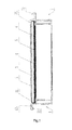
- Drawing 1 shows an overall sectional view of the structure of the integration unit for solar energy module covered by this patent.
- Drawing 2 shows a sectional view of the structure of the junction between a rear frame profile and the profile of the front frame of the neighboring solar energy module, in the case where several integration blocks for solar energy module referred to in FIG. present patent were assembled together.
- Drawing 3 shows a sectional view of the structure of the junction between two side jamb sections of two neighboring integration units for solar energy module, in the case where several integration blocks for solar energy module referred to in FIG. present patent were assembled together.
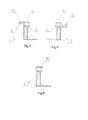
- Drawing 4 shows a cross-section of the profile of the front frame of an integration unit for solar energy module.
- Drawing 5 shows a cross-section of the rear frame profile of a solar energy module integration block.
- Drawing 6 shows a cross section of the side jamb profiles of the frame of an integration block for solar energy module.
- an integration unit for solar energy module comprises a solar module and assembly components.
- the structure of the solar energy module is similar to the traditional structure, namely it comprises a tempered glass (3), an EVA encapsulant layer (4), photovoltaic cells (5), another layer of EVA encapsulant ( 6) and a back layer in "Tedlar; TPT ".
- the assembly components include the front frame section (1), the rear frame section (7) and two sections for the side frame members (2), which components are capable of being assembled to form a rectangular frame .
- the front, rear and side frame profiles can be made of aluminum profile as well as thermoformed plastic or other material.
- the integration unit for solar energy module of this patent due to the presence of a front recess on the profile of the front frame and the rear frame section of a rear recess that comes to work in complementarity with the front installation, during the installation of several integration blocks for solar energy module, from front to back, the neighboring front and rear recesses come to nest the ones in the others by simple pose, simplifying much of the assembly.
- the roof covered by this patent comprises several integration blocks for solar energy module covered by this patent assembled by embedding.
- the rear mounting (72) of the rear frame profile (7) of a solar energy module integration block is adapted by embedding in one front recess (12) of the front frame profile (1) of the neighboring integration unit for solar energy module and a U-shaped seal (10) is installed between the front complementary recesses (12) and rear (72), so as to ensure the seal between the front recesses (12) and rear (72) and thus prevent any infiltration of rainwater or other infiltration.
- the upper surface (121) of the front recess (12) of two module integration blocks with solar energy installed together and the upper surface (711) of the mounting slide (71) of the rear frame profile (7) are on the same plane.
- the profiles of the lateral uprights (2) of the frames of two neighboring solar energy module integration blocks are connected together by a fixing profile and screws (40).
- the fastening profile it will be possible to use an existing structure, but in the case where it is necessary to increase the impermeability, the priority is the fastening profile of this patent.
- the fastening profile comprises a U-shaped body (91) and two fastening tabs (92) elongated outwardly at the ends of the uprights of the U-shaped body.
- the upper face of the fastening tabs is inclined at an angle. which allows one side to reduce the amount of material and reduce the cost price and on the other hand to facilitate the flow of rainwater.
- the fixing profile can be made of silicone rubber.
- the inner face of the fastening lugs (92) and the upper part of the outer face of the profiles of the lateral uprights (2) of the frames are supported against one another and between the fastening section (92) and the upper face of the profiles of the lateral uprights (2) of the frames is placed a strip sealing ring (20) whose cross section represents a dash; the sealing strip (20) can extend outside the fixing lugs (92), in order to improve the seal between the fixing lugs (92) and the profiles of the lateral uprights (2) frames.
- Screws (40) pass through the U-shaped body (91) and are connected to the chassis installed on the roof.
- a sealing washer (30) may be inserted between the screws and the U-shaped body (91).
- the integration blocks for solar energy module used by the roof presented here are not only simple to mount, but because of the possibility of inserting during mounting a profile between the front (1) and rear (7) recesses. ), inserting a sealing washer (30) between the screws and the U-shaped body (91) of the fastening profile and inserting a sealing strip (20) between the fastening tabs (92) of the profile fasteners and the profiles of the lateral uprights (2) of the frames.
- the solar energy module integration blocks not only can be used in a traditional photovoltaic system, but can be used on a roof that must be rainproof without laying an additional waterproof layer and ensure that the roof is watertight .
Landscapes
- Engineering & Computer Science (AREA)
- Chemical & Material Sciences (AREA)
- Mechanical Engineering (AREA)
- Sustainable Development (AREA)
- Sustainable Energy (AREA)
- Thermal Sciences (AREA)
- Physics & Mathematics (AREA)
- Combustion & Propulsion (AREA)
- Life Sciences & Earth Sciences (AREA)
- General Engineering & Computer Science (AREA)
- Architecture (AREA)
- Civil Engineering (AREA)
- Structural Engineering (AREA)
- Photovoltaic Devices (AREA)
- Roof Covering Using Slabs Or Stiff Sheets (AREA)
Applications Claiming Priority (1)
| Application Number | Priority Date | Filing Date | Title |
|---|---|---|---|
| CN2010201075411U CN201594543U (zh) | 2010-02-04 | 2010-02-04 | 太阳能电池模块及由该太阳能电池模块组装的屋顶 |
Publications (2)
| Publication Number | Publication Date |
|---|---|
| EP2354718A2 true EP2354718A2 (de) | 2011-08-10 |
| EP2354718A3 EP2354718A3 (de) | 2012-04-25 |
Family
ID=42776610
Family Applications (1)
| Application Number | Title | Priority Date | Filing Date |
|---|---|---|---|
| EP10164176A Withdrawn EP2354718A3 (de) | 2010-02-04 | 2010-05-27 | Integrationsblock für Solarmodul und mit solchen Blocks versehenes Dach |
Country Status (2)
| Country | Link |
|---|---|
| EP (1) | EP2354718A3 (de) |
| CN (1) | CN201594543U (de) |
Cited By (4)
| Publication number | Priority date | Publication date | Assignee | Title |
|---|---|---|---|---|
| CN102514818A (zh) * | 2011-12-08 | 2012-06-27 | 常州天合光能有限公司 | 两光伏组件叠合包装方式 |
| FR2975174A1 (fr) * | 2011-05-10 | 2012-11-16 | 3I Plus | Cadre pour panneau photovoltaique, tuile ainsi pourvue |
| EP2520876B1 (de) * | 2011-05-04 | 2013-04-03 | V-Energie S.r.L. | Bausatz zur Herstellung eines photovoltaischen Daches |
| EP2642218A1 (de) * | 2012-03-23 | 2013-09-25 | Brandoni Solare S.p.A. | Modulare Vorrichtung zur architektonischen Integration von rahmenlosen Solarmodulen |
Families Citing this family (10)
| Publication number | Priority date | Publication date | Assignee | Title |
|---|---|---|---|---|
| CN102296759A (zh) * | 2011-05-26 | 2011-12-28 | 泰通(泰州)工业有限公司 | 一种嵌入式光伏屋顶组件及其屋顶安装结构 |
| CN102339880A (zh) * | 2011-06-23 | 2012-02-01 | 泰通(泰州)工业有限公司 | 一种快速安装光伏组件边框 |
| CN102400523B (zh) * | 2011-07-28 | 2015-01-21 | 皇明洁能控股有限公司 | 太阳能屋顶系统 |
| CN102593220B (zh) * | 2012-03-01 | 2013-10-23 | 安徽长远绿色能源有限公司 | 一种用于光伏蜂窝组件模块的铝合金边框 |
| CN103362258B (zh) * | 2012-03-28 | 2015-12-02 | 中电电气(上海)太阳能科技有限公司 | 快装型太阳能屋瓦组件 |
| CN103206050B (zh) * | 2013-01-22 | 2015-04-15 | 于勤勇 | 太阳能光伏光热屋顶系统 |
| CN105227110A (zh) * | 2015-10-19 | 2016-01-06 | 广东大粤新能源科技股份有限公司 | 太阳能光伏组件扣接式拼接密封结构 |
| US10505492B2 (en) | 2016-02-12 | 2019-12-10 | Solarcity Corporation | Building integrated photovoltaic roofing assemblies and associated systems and methods |
| CN108412141A (zh) * | 2018-05-16 | 2018-08-17 | 蚌埠时代塑业有限公司 | 光伏瓦侧框连接组件 |
| CN110725481A (zh) * | 2019-09-20 | 2020-01-24 | 嘉兴市中法市政工程有限公司 | 遮阳挡雨板安装拼接机构 |
Family Cites Families (5)
| Publication number | Priority date | Publication date | Assignee | Title |
|---|---|---|---|---|
| DE2721343A1 (de) * | 1977-05-12 | 1978-11-23 | Harald Dr Ing Bitter | Vorrichtung zur energiegewinnung aus sonnenstrahlung |
| FR2465315A1 (fr) * | 1979-09-10 | 1981-03-20 | Radiotechnique Compelec | Panneau generateur photovoltaique assurant l'etancheite aux intemperies d'une toiture par pose directe sur la charpente |
| CH684202A5 (de) * | 1991-07-11 | 1994-07-29 | Plaston Ag Kunststoffwerk Hans | Dacheindeckung und Bauelement mit Solarzellen. |
| DE19521098A1 (de) * | 1995-06-09 | 1996-12-12 | Wilfried Bonn | Bauelement mit fotoelektrischen Zellen und damit ausgestattete Dacheindeckung |
| JP2003336357A (ja) * | 2002-05-20 | 2003-11-28 | Sekisui Chem Co Ltd | 太陽エネルギー集収装置の取付構造 |
-
2010
- 2010-02-04 CN CN2010201075411U patent/CN201594543U/zh not_active Expired - Fee Related
- 2010-05-27 EP EP10164176A patent/EP2354718A3/de not_active Withdrawn
Non-Patent Citations (1)
| Title |
|---|
| None |
Cited By (5)
| Publication number | Priority date | Publication date | Assignee | Title |
|---|---|---|---|---|
| EP2520876B1 (de) * | 2011-05-04 | 2013-04-03 | V-Energie S.r.L. | Bausatz zur Herstellung eines photovoltaischen Daches |
| FR2975174A1 (fr) * | 2011-05-10 | 2012-11-16 | 3I Plus | Cadre pour panneau photovoltaique, tuile ainsi pourvue |
| CN102514818A (zh) * | 2011-12-08 | 2012-06-27 | 常州天合光能有限公司 | 两光伏组件叠合包装方式 |
| CN102514818B (zh) * | 2011-12-08 | 2013-11-20 | 常州天合光能有限公司 | 两光伏组件叠合包装结构 |
| EP2642218A1 (de) * | 2012-03-23 | 2013-09-25 | Brandoni Solare S.p.A. | Modulare Vorrichtung zur architektonischen Integration von rahmenlosen Solarmodulen |
Also Published As
| Publication number | Publication date |
|---|---|
| CN201594543U (zh) | 2010-09-29 |
| EP2354718A3 (de) | 2012-04-25 |
Similar Documents
| Publication | Publication Date | Title |
|---|---|---|
| EP2354718A2 (de) | Integrationsblock für Solarmodul und mit solchen Blocks versehenes Dach | |
| JP4661021B2 (ja) | 太陽電池モジュール、太陽電池モジュールの設置構造、及びその設置構造を有した発電機能付き屋根 | |
| CA2684545C (fr) | Bati support d'un panneau tel que panneau photoelectrique et paroi exterieure d'un batiment comportant de tels batis | |
| CA2931337C (fr) | Panneau, assemblage de panneaux et toiture associee | |
| EP2023402A1 (de) | Profil und Montagevorrichtung für Photovoltaikpaneele in eine Gebäudestruktur, insbesondere in ein Dach, und diese Elemente integrierende Gebäudestruktur | |
| EP3303723A1 (de) | Platte, anordnung der platten und zugehöriges dach | |
| WO2009153497A2 (fr) | Dispositif de support de modules de récupération d'énergie solaire, unité de récupération d'énergie solaire et procédé de montage de modules de récupération d'énergie solaire | |
| EP2195495A1 (de) | Vorrichtung zur befestigung von pv-modulen auf einem dach mit befestigungsmitteln für den durchlass eines luftstroms zwischen einer grundfläche und dem pv-modul | |
| EP2588815B1 (de) | Anlage zur gewinnung von sonnenenergie | |
| JPWO2002004761A1 (ja) | 太陽電池モジュール、太陽電池モジュールの設置構造、及びその設置構造を有した発電機能付き屋根、並びに太陽電池モジュールの設置方法 | |
| EP2724088A1 (de) | Platte, plattenanordnung und zugehörige bedachung | |
| WO2021074339A1 (fr) | Tuile photovoltaique plate, procédé de pose et couverture obtenue | |
| CA2954134C (fr) | Panneau muni d'un dispositif photovoltaique | |
| EP2718635B1 (de) | Befestigungs- und dichtungssystem zur erzeugung eines solardaches und damit erzeugtes solardach | |
| FR2943369A1 (fr) | Profile et systeme de fixation et d'etancheite pour la realisation d'une toiture solaire, et toiture solaire obtenue | |
| EP1106771A2 (de) | Bauelement mit einer Kabeldurchführung sowie Herstellungsverfahren für dasselbe | |
| EP2491197A2 (de) | Stromerzeugendes abdeckelement | |
| WO2010122241A2 (fr) | Pièce de fixation pour l'assemblage d'un module, notamment photovoltaïque, sur une tôle nervurée, assemblage et utilisation pour la réalisation d'une couverture de bâtiment et procede de fabrication associe | |
| FR2937663A1 (fr) | Systeme d'etancheite pour couverture de toiture,notamment pourvue de panneaux solaires,et construction comportant une telle couverture | |
| FR2999205A1 (fr) | Systeme de fixation et d’etancheite pour la realisation d’une toiture solaire comprenant des vitrages electrochromes, et toiture solaire obtenue | |
| JP5839344B2 (ja) | 太陽電池パネルを用いた外装構造 | |
| FR2963089A1 (fr) | Structure de maintien en position de panneaux photovoltaiques par rapport a un bati | |
| FR2956681A1 (fr) | Dispositif pour l'integration de panneaux photovoltaiques sur un toit | |
| FR2546552A1 (fr) | Enveloppe a paroi multiple isolee thermiquement et munie de moyens de recuperation d'energie solaire pour delimiter au moins en partie un volume habitable | |
| FR3046296A1 (fr) | Dispositif photovoltaique avec boitier de jonction electrique, procede de fabrication et utilisation dudit dispositif |
Legal Events
| Date | Code | Title | Description |
|---|---|---|---|
| PUAI | Public reference made under article 153(3) epc to a published international application that has entered the european phase |
Free format text: ORIGINAL CODE: 0009012 |
|
| AK | Designated contracting states |
Kind code of ref document: A2 Designated state(s): AL AT BE BG CH CY CZ DE DK EE ES FI FR GB GR HR HU IE IS IT LI LT LU LV MC MK MT NL NO PL PT RO SE SI SK SM TR |
|
| AX | Request for extension of the european patent |
Extension state: BA ME RS |
|
| PUAL | Search report despatched |
Free format text: ORIGINAL CODE: 0009013 |
|
| AK | Designated contracting states |
Kind code of ref document: A3 Designated state(s): AL AT BE BG CH CY CZ DE DK EE ES FI FR GB GR HR HU IE IS IT LI LT LU LV MC MK MT NL NO PL PT RO SE SI SK SM TR |
|
| AX | Request for extension of the european patent |
Extension state: BA ME RS |
|
| RIC1 | Information provided on ipc code assigned before grant |
Ipc: H01L 31/042 20060101ALI20120319BHEP Ipc: F24J 2/52 20060101AFI20120319BHEP |
|
| STAA | Information on the status of an ep patent application or granted ep patent |
Free format text: STATUS: THE APPLICATION IS DEEMED TO BE WITHDRAWN |
|
| 18D | Application deemed to be withdrawn |
Effective date: 20121026 |