EP2354504A2 - Vorrichtung zur Regelung der Abgasemission für einen Verbrennungsmotor - Google Patents
Vorrichtung zur Regelung der Abgasemission für einen Verbrennungsmotor Download PDFInfo
- Publication number
- EP2354504A2 EP2354504A2 EP11150699A EP11150699A EP2354504A2 EP 2354504 A2 EP2354504 A2 EP 2354504A2 EP 11150699 A EP11150699 A EP 11150699A EP 11150699 A EP11150699 A EP 11150699A EP 2354504 A2 EP2354504 A2 EP 2354504A2
- Authority
- EP
- European Patent Office
- Prior art keywords
- temperature
- catalyst
- hydrocarbon
- occluding
- hydrocarbons
- Prior art date
- Legal status (The legal status is an assumption and is not a legal conclusion. Google has not performed a legal analysis and makes no representation as to the accuracy of the status listed.)
- Granted
Links
Images


Classifications
-
- F—MECHANICAL ENGINEERING; LIGHTING; HEATING; WEAPONS; BLASTING
- F02—COMBUSTION ENGINES; HOT-GAS OR COMBUSTION-PRODUCT ENGINE PLANTS
- F02D—CONTROLLING COMBUSTION ENGINES
- F02D41/00—Electrical control of supply of combustible mixture or its constituents
- F02D41/02—Circuit arrangements for generating control signals
- F02D41/021—Introducing corrections for particular conditions exterior to the engine
- F02D41/0235—Introducing corrections for particular conditions exterior to the engine in relation with the state of the exhaust gas treating apparatus
- F02D41/027—Introducing corrections for particular conditions exterior to the engine in relation with the state of the exhaust gas treating apparatus to purge or regenerate the exhaust gas treating apparatus
-
- F—MECHANICAL ENGINEERING; LIGHTING; HEATING; WEAPONS; BLASTING
- F01—MACHINES OR ENGINES IN GENERAL; ENGINE PLANTS IN GENERAL; STEAM ENGINES
- F01N—GAS-FLOW SILENCERS OR EXHAUST APPARATUS FOR MACHINES OR ENGINES IN GENERAL; GAS-FLOW SILENCERS OR EXHAUST APPARATUS FOR INTERNAL-COMBUSTION ENGINES
- F01N13/00—Exhaust or silencing apparatus characterised by constructional features
- F01N13/009—Exhaust or silencing apparatus characterised by constructional features having two or more separate purifying devices arranged in series
-
- F—MECHANICAL ENGINEERING; LIGHTING; HEATING; WEAPONS; BLASTING
- F01—MACHINES OR ENGINES IN GENERAL; ENGINE PLANTS IN GENERAL; STEAM ENGINES
- F01N—GAS-FLOW SILENCERS OR EXHAUST APPARATUS FOR MACHINES OR ENGINES IN GENERAL; GAS-FLOW SILENCERS OR EXHAUST APPARATUS FOR INTERNAL-COMBUSTION ENGINES
- F01N3/00—Exhaust or silencing apparatus having means for purifying, rendering innocuous, or otherwise treating exhaust
- F01N3/08—Exhaust or silencing apparatus having means for purifying, rendering innocuous, or otherwise treating exhaust for rendering innocuous
- F01N3/0807—Exhaust or silencing apparatus having means for purifying, rendering innocuous, or otherwise treating exhaust for rendering innocuous by using absorbents or adsorbents
- F01N3/0814—Exhaust or silencing apparatus having means for purifying, rendering innocuous, or otherwise treating exhaust for rendering innocuous by using absorbents or adsorbents combined with catalytic converters, e.g. NOx absorption/storage reduction catalysts
-
- F—MECHANICAL ENGINEERING; LIGHTING; HEATING; WEAPONS; BLASTING
- F01—MACHINES OR ENGINES IN GENERAL; ENGINE PLANTS IN GENERAL; STEAM ENGINES
- F01N—GAS-FLOW SILENCERS OR EXHAUST APPARATUS FOR MACHINES OR ENGINES IN GENERAL; GAS-FLOW SILENCERS OR EXHAUST APPARATUS FOR INTERNAL-COMBUSTION ENGINES
- F01N3/00—Exhaust or silencing apparatus having means for purifying, rendering innocuous, or otherwise treating exhaust
- F01N3/08—Exhaust or silencing apparatus having means for purifying, rendering innocuous, or otherwise treating exhaust for rendering innocuous
- F01N3/0807—Exhaust or silencing apparatus having means for purifying, rendering innocuous, or otherwise treating exhaust for rendering innocuous by using absorbents or adsorbents
- F01N3/0828—Exhaust or silencing apparatus having means for purifying, rendering innocuous, or otherwise treating exhaust for rendering innocuous by using absorbents or adsorbents characterised by the absorbed or adsorbed substances
- F01N3/0835—Hydrocarbons
-
- F—MECHANICAL ENGINEERING; LIGHTING; HEATING; WEAPONS; BLASTING
- F01—MACHINES OR ENGINES IN GENERAL; ENGINE PLANTS IN GENERAL; STEAM ENGINES
- F01N—GAS-FLOW SILENCERS OR EXHAUST APPARATUS FOR MACHINES OR ENGINES IN GENERAL; GAS-FLOW SILENCERS OR EXHAUST APPARATUS FOR INTERNAL-COMBUSTION ENGINES
- F01N3/00—Exhaust or silencing apparatus having means for purifying, rendering innocuous, or otherwise treating exhaust
- F01N3/08—Exhaust or silencing apparatus having means for purifying, rendering innocuous, or otherwise treating exhaust for rendering innocuous
- F01N3/10—Exhaust or silencing apparatus having means for purifying, rendering innocuous, or otherwise treating exhaust for rendering innocuous by thermal or catalytic conversion of noxious components of exhaust
- F01N3/103—Oxidation catalysts for HC and CO only
-
- F—MECHANICAL ENGINEERING; LIGHTING; HEATING; WEAPONS; BLASTING
- F01—MACHINES OR ENGINES IN GENERAL; ENGINE PLANTS IN GENERAL; STEAM ENGINES
- F01N—GAS-FLOW SILENCERS OR EXHAUST APPARATUS FOR MACHINES OR ENGINES IN GENERAL; GAS-FLOW SILENCERS OR EXHAUST APPARATUS FOR INTERNAL-COMBUSTION ENGINES
- F01N2560/00—Exhaust systems with means for detecting or measuring exhaust gas components or characteristics
- F01N2560/06—Exhaust systems with means for detecting or measuring exhaust gas components or characteristics the means being a temperature sensor
-
- F—MECHANICAL ENGINEERING; LIGHTING; HEATING; WEAPONS; BLASTING
- F01—MACHINES OR ENGINES IN GENERAL; ENGINE PLANTS IN GENERAL; STEAM ENGINES
- F01N—GAS-FLOW SILENCERS OR EXHAUST APPARATUS FOR MACHINES OR ENGINES IN GENERAL; GAS-FLOW SILENCERS OR EXHAUST APPARATUS FOR INTERNAL-COMBUSTION ENGINES
- F01N2560/00—Exhaust systems with means for detecting or measuring exhaust gas components or characteristics
- F01N2560/14—Exhaust systems with means for detecting or measuring exhaust gas components or characteristics having more than one sensor of one kind
-
- F—MECHANICAL ENGINEERING; LIGHTING; HEATING; WEAPONS; BLASTING
- F01—MACHINES OR ENGINES IN GENERAL; ENGINE PLANTS IN GENERAL; STEAM ENGINES
- F01N—GAS-FLOW SILENCERS OR EXHAUST APPARATUS FOR MACHINES OR ENGINES IN GENERAL; GAS-FLOW SILENCERS OR EXHAUST APPARATUS FOR INTERNAL-COMBUSTION ENGINES
- F01N2900/00—Details of electrical control or of the monitoring of the exhaust gas treating apparatus
- F01N2900/06—Parameters used for exhaust control or diagnosing
- F01N2900/16—Parameters used for exhaust control or diagnosing said parameters being related to the exhaust apparatus, e.g. particulate filter or catalyst
- F01N2900/1618—HC-slip from catalyst
-
- F—MECHANICAL ENGINEERING; LIGHTING; HEATING; WEAPONS; BLASTING
- F01—MACHINES OR ENGINES IN GENERAL; ENGINE PLANTS IN GENERAL; STEAM ENGINES
- F01N—GAS-FLOW SILENCERS OR EXHAUST APPARATUS FOR MACHINES OR ENGINES IN GENERAL; GAS-FLOW SILENCERS OR EXHAUST APPARATUS FOR INTERNAL-COMBUSTION ENGINES
- F01N2900/00—Details of electrical control or of the monitoring of the exhaust gas treating apparatus
- F01N2900/06—Parameters used for exhaust control or diagnosing
- F01N2900/16—Parameters used for exhaust control or diagnosing said parameters being related to the exhaust apparatus, e.g. particulate filter or catalyst
- F01N2900/1621—Catalyst conversion efficiency
-
- F—MECHANICAL ENGINEERING; LIGHTING; HEATING; WEAPONS; BLASTING
- F02—COMBUSTION ENGINES; HOT-GAS OR COMBUSTION-PRODUCT ENGINE PLANTS
- F02D—CONTROLLING COMBUSTION ENGINES
- F02D2200/00—Input parameters for engine control
- F02D2200/02—Input parameters for engine control the parameters being related to the engine
- F02D2200/08—Exhaust gas treatment apparatus parameters
- F02D2200/0802—Temperature of the exhaust gas treatment apparatus
Definitions
- the present invention relates to an exhaust emission control device for an internal combustion engine that estimates a quantity of hydrocarbon occluded in an occluding agent of an exhaust system.
- an exhaust emission control system that purifies hydrocarbon emitted from an internal combustion engine includes catalytic converter rhodium, an oxidation catalyst, or the like, provided in a vehicle exhaust system is know.
- the catalyst includes a supported precious metal component exhibiting oxidation, such as platinum, palladium, and rhodium, and efficient hydrocarbon purification is implemented.
- hydrocarbon oxidation effected by precious metal requires a predetermined catalyst temperature. Sufficient performance cannot be exhibited at cold start of an internal combustion engine during which a catalyst is cold. Accordingly, there has been developed a technique of using in combination an occluding member having a feature of temporarily occluding hydrocarbon emitted when an activating temperature of a catalyst is not reached, thereby enhancing emission purification performance.
- JP-A-2005-240726 includes a description about an occluding catalyst (an HC trap catalyst) including a combination of catalytic converter rhodium with an occluding material (an HC trap material) that adsorbs or desorbs hydrocarbon emitted from an internal combustion engine.
- an occluding catalyst adsorbs (traps) hydrocarbon when the catalyst is at a comparatively low temperature.
- the catalyst oxidizes the hydrocarbon while desorbing the same, thereby purifying emissions.
- a general hydrocarbon occluding member has a ceiling on the quantity of hydrocarbon capable of being occluded, and a predetermined quantity of hydrocarbon or more cannot be occluded. Accordingly, operation for periodically desorbing the occluded hydrocarbon is required.
- hydrocarbon occluding member is applied to an exhaust system of a diesel engine, hydrocarbon is likely to be excessively stored during idling operation performed at an extremely low emission temperature. Therefore, delayed desorbing operation may result in deterioration of the occluding member. Consequently, it is important to accurately ascertain the quantity of hydrocarbon in an occluding member and perform desorbing operation without a delay.
- the technique described in connection with JP-A-2005-240726 provides a description including detecting combustion-related fuel property pertaining to a state of an internal combustion engine, calculating a quantity of hydrocarbon in emissions appropriate for the fuel property, and estimating a quantity of hydrocarbon occluded. Such control is said to make it possible to desorb hydrocarbon at appropriate timing from an occluding catalyst.
- a desorbing characteristic of the hydrocarbon occluded in the occluding member varies according to the temperature at which the hydrocarbon was trapped. Specifically, a wide variety of types of hydrocarbon having different boiling points are occluded in the occluding member. A distribution of boiling points of these types of hydrocarbons is dependent on temperature conditions employed during trapping operation as well as on a distribution of boiling points of hydrocarbons in emissions. Provided that the quantity of occluded hydrocarbon is calculated without taking into account such temperature conditions and that an estimated quantity of desorbed hydrocarbon is simply subtracted from the thus-calculated quantity of occluded hydrocarbon, a quantity of hydrocarbon that has a high boiling point and that would not originally be desorbed will also be subtracted. Therefore, the quantity of occluded hydrocarbon is often underestimated, and desorbing operation cannot be performed at accurate timing.
- One of objects of the present invention has been conceived in light of such a problem and is to enhance accuracy of estimation of a quantity of hydrocarbon occluded in an occluding member.
- an exhaust emission control device for an internal combustion engine comprising: an occluding member that is provided in an exhaust system of an internal combustion engine and that traps and desorbs a plurality of types of hydrocarbons having different boiling points in emissions; first calculation means that estimates a distribution of presence of each type of the hydrocarbons to be trapped by the occluding member and that calculates an occlusion quantity of the occluding member for each type of the hydrocarbons from the quantity of trapped hydrocarbons; and control means that performs control operation for purifying the hydrocarbons occluded in the occluding member according to the occlusion quantity calculated by the first calculation means.
- the exhaust emission control device for an internal combustion engine may further have second calculation means that subtracts in sequence a quantity of the hydrocarbon desorbed from the occluding member from the quantity of occluded hydrocarbon having a lower boiling point among the occlusion quantities calculated by the first calculation means, thereby calculating the quantity of hydrocarbon occluded in the occluding member.
- the exhaust emission control device for an internal combustion engine may also be configured so as to further have first catalyst temperature detection means for detecting a first catalyst temperature that is a catalyst temperature of the occluding member, and the first calculation means may calculate a quantity of trapped hydrocarbon having a boiling point that is equal to or higher than the first catalyst temperature detected by the first catalyst temperature detection means.
- the second calculation means may also be configured so as to subtract the desorption quantity solely from the quantity of occluded hydrocarbon having a boiling point that is less than the first catalyst temperature detected by the first catalyst temperature detection means.
- the exhaust emission control device for an internal combustion engine has an oxidation catalyst provided in an upstream position with reference to an occluding catalyst in the exhaust and second catalyst temperature detection means that detects a catalyst temperature of the oxidation catalyst as a second catalyst temperature.
- the first calculation means may also be configured so as to calculate a quantity of trapped hydrocarbon having a boiling point that is equal to or higher than either the first catalyst temperature detected by the first catalyst temperature detection means or the second catalyst temperature detected by the second catalyst temperature detection means, whichever is higher.
- the exhaust emission control device for an internal combustion engine of the present invention makes it possible to enhance accuracy of estimation of an occlusion quantity by estimating a distribution of presence of a trapped hydrocarbon according to a distribution of boiling points of hydrocarbons included in emissions flowing into an occluding member.
- An engine 1 (an internal combustion engine) shown in Fig. 1 is a diesel engine that takes light oil containing various hydrocarbons (HC) as fuel.
- An exhaust passageway 6 and an intake passageway 7 are connected to the engine 1.
- Intake air is introduced into combustion chambers of cylinders of the engine 1 by way of the intake passageway 7, and an exhaust gas (hereinafter referred to simply as an "emission") resulting from combustion is discharged outside of the vehicle by way of the exhaust passageway 6.
- Hydrocarbons having a plurality of carbon numbers are mixedly present in the fuel of the engine 1.
- a plurality of types of hydrocarbons having different boiling points also mixedly exist in hydrocarbons contained in the emissions.
- a controller 10 controls a fuel-air ratio, a quantity of intake air, a quantity of fuel injection, fuel injection timing, a quantity of post fuel injection, and others, that are related to combustion reaction occurred in the combustion chambers of the engine 1.
- the controller 10 is a so-called ECU (Electric Control Unit).
- An oxidation catalyst 3 and an occluding catalyst 2 are placed in the exhaust passageway 6 in a decreasing sequence of emission flow from an upstream position.
- the occluding catalyst 2 (an occluding member) is a catalyst unit that has an occluding layer provided on a surface of a catalyst support. In some instance, the unit additionally has a precious metal catalyst layer.
- the occluding layer is a layer containing various types of zeolites having a characteristic of occluding hydrocarbons contained in emissions.
- the precious metal catalyst layer is a layer that contains active alumina carrying a precious metal component for enhancing a hydrocarbon oxidation function.
- the occluding catalyst 2 traps hydrocarbon at a low catalyst temperature, and the thus-trapped hydrocarbon is occluded in the occluding layer. As the catalyst temperature increases, the occluding catalyst 2 desorbs the trapped hydrocarbon, and the precious metal catalyst layer eliminates the hydrocarbon through oxidation.
- a regeneration temperature T c is set as a target value of a catalyst temperature to be operated for desorbing hydrocarbon from the occluding catalyst 2.
- the regeneration temperature T c is a catalyst temperature that makes it possible to desorb nearly all occluded hydrocarbon without involvement of deterioration of the occluding catalyst 2, thereby purifying the occluding catalyst.
- the regeneration temperature T c is set to; for instance, 400 [°C] or thereabouts.
- purge control controlling an exhaust temperature in such a way that the catalyst temperature of the occluding catalyst 2 reaches the regeneration temperature T c is called purge control.
- the controller 10 to be described later implements purge control.
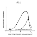
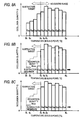
- a hydrocarbon desorbing characteristic of the occluding catalyst 2 is now described by reference to Fig. 2 .
- a solid-line plot in Fig. 2 denotes a test result showing a concentration of hydrocarbon detected at a downstream position with respect to the catalyst when the catalyst temperature of the occluding catalyst 2, which occludes hydrocarbon as a result of the engine 1 having continually performed idling operation for a predetermined time while the catalyst temperature is held at a predetermined temperature T A [°C], is changed from a low temperature to a high temperature.
- a broken-line plot in the drawing denotes a test result yielded when the idling operation is shortened while the catalyst temperature is maintained at a predetermined temperature T B [°C] by means of changing conditions for letting the occluding catalyst 2 of the same type occlude hydrocarbon.
- a dashed line in the drawing denotes a reference line showing a concentration of hydrocarbon detected at an upstream position with respect to the catalyst.
- the solid-line plot in Fig. 2 shows that hydrocarbon is desorbed over an entire temperature range from the predetermined temperature T A employed during trapping operation to the regeneration temperature T C . Even in a broken-line graph, hydrocarbons are desorbed over an entire temperature range from the predetermined temperature T B employed during trapping operation to the regeneration temperature T C . In short, when a catalyst temperature employed during trapping operation is constantly maintained, only hydrocarbons having boiling points that are equal to or higher than the catalyst temperature are occluded in the occluding catalyst 2, and hydrocarbons having boiling points that are less than the catalyst temperature are not occluded in the occluding catalyst 2.
- the regeneration temperature T c can be considered to be the maximum value of a boiling point of the hydrocarbon trapped in the occluding catalyst 2.
- the oxidation catalyst 3 is a catalyst that carries on its surface a precious metal component and has an ability to oxidize various components in emissions. Components in emissions purified by the oxidation catalyst 3 include carbon monoxide (CO), hydrocarbons, and others.
- the oxidation catalyst 3 in a diesel engine exhaust system in which a fuel-air ratio in emissions is set to a lean atmosphere oxidizes nitrogen monoxide, carbon monoxide, and hydrocarbon, thereby producing nitrogen dioxide, carbon dioxide, and a moisture.
- the catalyst temperature of the oxidation catalyst 3 is less than the predetermined activating temperature, hydrocarbon is not purified and captured by the occluding catalyst 2 disposed downstream.
- a first temperature sensor 4 (first catalyst temperature detection means) is disposed downstream of the occluding catalyst 2, and a second temperature sensor 5 (second catalyst temperature detection means) is disposed downstream of the oxidation catalyst 3.
- the first temperature sensor 4 detects a catalyst temperature of the occluding catalyst 2
- the second temperature sensor 5 detects a catalyst temperature of the oxidation catalyst 3.
- the catalyst temperature of the occluding catalyst 2 is hereunder called a "first catalyst temperature T 1 ”
- the catalyst temperature of the oxidation catalyst 3 is hereunder called a "second catalyst temperature T 2 .”
- the first catalyst temperature T 1 detected by the first temperature sensor 4 and the second catalyst temperature T 2 detected by the second temperature sensor 5 are input to the controller 10.
- the engine 1 is also equipped, side by side, with an engine speed sensor 21 for detecting an engine speed N E , an engine coolant temperature sensor 22 for detecting a temperature T HW of an engine coolant, and a torque sensor 25 for detecting torque T OR of a drive shaft of the engine 1.
- a linear fuel-air ratio sensor 23 for detecting a fuel-air ratio R A/F is disposed on the exhaust passageway 6, and an intake temperature sensor 24 for detecting a temperature T HA of an intake air is disposed on the intake passageway 7.
- the engine speed N E , the engine coolant temperature T HW , the engine torque T OR , the fuel-air ratio R A/F , and the intake temperature T HA detected by the various sensors are input to the controller 10.
- a vehicle speed sensor 26 for detecting a vehicle speed V is provided at an arbitrary position on a vehicle. The thus-detected vehicle speed V is also input to the controller 10.
- the controller 10 is an electronic controller offered as an LSI device that results from integration of known microprocessors, ROM, RAM, and the like.
- the engine speed sensor 21, the engine coolant temperature sensor 22, the linear fuel-air ratio sensor 23, the intake temperature sensor 24, the torque sensor 25, the vehicle speed sensor 26, the first temperature sensor 4, and the second temperature sensor 5 are connected to an input side of the controller 10. According to input information from these sensors, the controller 10 performs occlusion quantity estimation control and purge control.
- Occlusion quantity estimation control is control operation for calculating, in an estimating manner, the quantity Q of hydrocarbon occluded in the occluding catalyst 2.
- the occlusion quantity Q is calculated according to the engine speed N E , the engine coolant temperature T HW , the fuel-air ratio R A/F , the intake temperature T HA , the engine torque T OR , the vehicle speed V, the first catalyst temperature T 1 , and the second catalyst temperature T 2 .
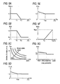
- Basic idea of occlusion quantity estimation control is described by reference to Fig. 3 .
- a relationship, such as that designated by a solid line in Fig. 3 , is assumed to exist between the catalyst temperature of the occluding catalyst 2 and a desorption speed V de of hydrocarbon. Namely, when a catalyst temperature T is less than a predetermined temperature T 01 , the desorption speed comes to V de 0, so that hydrocarbon is not desorbed. When the catalyst temperature is the predetermined temperature T 01 or more, hydrocarbon is desorbed.
- the desorption speed V de corresponds to a desorption quantity achieved per unit time.
- the desorption speed V de is assumed to linearly increase within a range where the catalyst temperature T changes from the predetermined temperature T 01 to a regeneration temperature T 03 .
- the regeneration temperature T 03 signifies a catalyst temperature identical with the regeneration temperature T c .
- the desorption speed V de achieved when the catalyst temperature T is a predetermined temperature T 02 is assumed to be a predetermined speed V 1 .
- hydrocarbons whose boiling points fall within a temperature range from the predetermined temperature T 01 to the predetermined temperature T 02 are assumed to be desorbed, and hydrocarbons whose boiling points fall within a temperature range from the predetermined temperature T 02 to the regeneration temperature T 03 are assumed to be trapped.
- hydrocarbons whose boiling points fall within a temperature range A shown in Fig. 3 are considered to be untrapped, and hydrocarbons whose boiling points fall within a temperature range B are considered to be trapped.
- the hydrocarbons whose boiling points fall within the temperature range A are considered to be desorbed, and the hydrocarbons whose boiling points fall within the temperature range B are considered not to be desorbed.
- hydrocarbons are classified into a plurality of types having different boiling points, and a trap quantity and a desorption quantity are calculated for each type.
- a boiling point distribution model for hydrocarbons contained in the emissions flowing into the occluding catalyst 2.
- Hydrocarbons are herein supposed to have boiling points that range from a first temperature B 1 to a third temperature B 3 .
- a distribution profile assumes a shape of an isosceles triangle.
- hydrocarbons having higher boiling points are distributed so as to become larger in quantity.
- hydrocarbons having lower boiling points are distributed so as to become larger in quantity.
- the distribution of boiling points of hydrocarbons trapped in the occluding catalyst 2 is assumed to imitate the foregoing distribution patterns in a range in excess of a catalyst temperature of the occluding catalyst 2.
- hydrocarbons trapped in the occluding catalyst 2 are first assumed to be limited to hydrocarbons having boiling points that are equal to or higher than the catalyst temperature T achieved at that time.
- a quantity of trapped hydrocarbons is now calculated on the basis of assumptions provided below. In relation to hydrocarbons having boiling points that fall within a range from the first temperature B 1 to the second temperature B 2 , hydrocarbons having higher boiling points are trapped in larger quantity.
- hydrocarbons having lower boiling points are trapped in larger quantity.
- hydrocarbons having lower boiling points among the hydrocarbons occluded in the occluding catalyst 2 are considered to be desorbed in an increasing sequence from a lower boiling point within a temperature range under the catalyst temperature of the occluding catalyst 2.
- the reason for this is that a degree of reactivity of desorption from the occluding catalyst 2 is dependent on a boiling point of hydrocarbon.
- Purge control is for forcefully desorbing and purifying the hydrocarbons occluded in the occluding catalyst 2. Purge control is performed when the occlusion quantity Q estimated by means of occlusion quantity estimation control has exceeded a predetermined threshold value Q TH .
- the predetermined threshold value Q TH is set to an arbitrary value in a range that is the hydrocarbon quantity Q MAX of the occluding catalyst 2 or less.
- An exhaust temperature is regulated by purge control in such a way that the catalyst temperature of the occluding catalyst 2 is maintained at the regeneration temperature T C for a predetermined period of time.
- One of objectives of purge control is to desorb hydrocarbons before the hydrocarbon occlusion quantity Q reaches the hydrocarbon quantity Q max .
- the objective becomes easier to attain, so long as the predetermined threshold value Q TH is set to a lower value. Namely, the objective becomes easier to attain with an increase in frequency of performance of purge control.
- purge control is performed so as to make an exhaust temperature higher than the exhaust temperature achieved during normal idling operation. For this reason, an increase in frequency of performance of purge control results in deterioration of fuel efficiency.
- Occlusion quantity estimation control of the present embodiment can also be said to be control for effecting estimated operation of an occlusion quantity Q with high accuracy from the foregoing viewpoint.
- the controller 10 has an estimation control block 11 and a purge control block 17 (control means) as a software configuration for implementing the respective control operations.
- These software programs are recorded in unillustrated memory and an unillustrated storage device. Functions which will be described below are implemented by reading the software program into a CPU, as required.
- the estimation control block 11 is assigned the previously described occlusion quantity estimation control and calculates, in an estimating manner, the hydrocarbon occlusion quantity Q in the occluding catalyst 2, as necessary.
- the estimation control block 11 is equipped with first calculation means including a trap quantity calculation block 12 and a distribution block 13; second calculation means including a desorption quantity calculation block 14 and a subtraction block 15; and a determination block 16.
- the trap quantity calculation block 12 is for calculating a quantity M hcad [g/sec]of hydrocarbon trapped in the occluding catalyst 2 per unit time.
- the trap quantity M hcad is given by the following equation.
- M hcad K adsorp ⁇ M hcin
- K adsorp is a trapping coefficient.
- M hcin is a quantity of inflow hydrocarbon.
- the trapping coefficient K adsorp designates a ratio of hydrocarbon trapped into the occluding catalyst 2 from emissions and is set according to the first catalyst temperature T 1 (the catalyst temperature of the occluding catalyst 2) and a characteristic of the occluding catalyst 2.
- the characteristic of the occluding catalyst 2 includes; for instance, a type, a composition, a structure, and the like, of a catalytic material.
- a predetermined value K 1 is given as the trapping coefficient K adsorp .
- the specific predetermined temperature T 12 may be determined according to a trapping characteristic of the occluding catalyst 2. For instance, a temperature of about 250 [°C] is conceivable for the predetermined temperature T 12 .
- M hcin K OXI ⁇ M hceng
- K OXI is an upstream slip coefficient.
- M hceng is an engine discharge.
- the upstream slip coefficient K OXI designates a ratio of hydrocarbon flowing into the occluding catalyst 2 without being purified by the oxidation catalyst 3 and is determined by the second catalyst temperature T 2 that is a catalyst temperature of the oxidation catalyst 3 and the characteristic of the oxidation catalyst 3.
- K OXI 1
- K OXI K 2
- T 21 ⁇ T 22 the coefficient gradually decreases with an increase in the second catalyst temperature T 2 .
- the upstream slip coefficient K OXI is set according to hydrocarbon purification efficiency of the oxidation catalyst 3. For instance, when the purification efficiency of the oxidation catalyst 3 reached the activating temperature is 90[%], the coefficient K 2 is set to 0.1 in a range that is equal to or higher than the second catalyst temperature T 2 equivalent to the activating temperature. It is desirable to set the predetermined temperatures T 21 and T 22 such that the upstream slip coefficient K OXI changes in a neighborhood of the activating temperature.
- the engine discharge M hceng [g/sec] designates a quantity of hydrocarbon discharged per unit time from the engine 1 and is given by the following equation.
- M hceng M hceng ⁇ 0 ⁇ K THW ⁇ K THA
- M hceng0 designates a basic discharge.
- K THW is a water temperature correction coefficient.
- K THA is an intake temperature correction coefficient.
- the basic discharge M hceng0 designates a standard hydrocarbon discharge per unit time estimated from an operating state of the engine 1. As shown in Fig. 5C , the basic discharge M hceng0 is calculated according to a map pertaining to the engine speed N E detected by the engine speed sensor 21 and the engine torque T OR detected by the torque sensor 25. The basic discharge M hceng0 is set so as to become greater with an increase in the engine speed N E or engine torque T OR . Specifically, the basic discharge M hceng0 is set so as to increase as an output of the engine 1 becomes greater.
- the predetermined temperature T HW1 is set to; for instance, 85[°C].
- the intake temperature correction coefficient K THA is a hydrocarbon discharge correction gain based on the intake temperature T HA .
- the intake temperature correction coefficient K THA is set so as to increase as the intake temperature is lower.
- the predetermined temperature T HA1 is set to; for instance, 25[°C].
- the distribution block 13 classifies trapped hydrocarbon into a plurality of types of hydrocarbon having different boiling points and calculates a trap quantity M hcad according to the types of hydrocarbon.
- the trap quantity M hcad calculated by the trap quantity calculation block 12 is distributed for each of the boiling points.
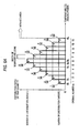
- Fig. 6A illustrates a distribution model of the trap quantity M hcad previously recorded in the distribution block 13.
- a horizontal axis shown in Fig. 6A represents temperatures corresponding to boiling points of trapped hydrocarbons.
- a width of an individual temperature zone corresponds to a width of a boiling point of hydrocarbon classified into the zone.
- a vertical axis shown in the drawing represents a distribution ratio of the trap quantity M hcad .
- a distribution ratio for each temperature zone is proportional to an area of the temperature zone.
- a range from the first temperature B 1 to the third temperature B 3 is divided at uniform intervals into eleven areas along the vertical axis, whereby a plurality of strip-shaped temperature zones are formed.
- the distribution ratio is determined in such a way that the largest quantity of hydrocarbon is distributed to the temperature zone including the second temperature B 2 .
- the hydrocarbon trapped into the occluding catalyst 2 exhibits a boiling point distribution analogous to the boiling point distribution of hydrocarbon in emissions flowing into the occluding catalyst 2. Therefore, the distribution model is formed into a shape that imitates an isosceles triangle taking a neighborhood of the second temperature B 2 as an apex, so as to follow a boiling point distribution of hydrocarbon in emissions shown in Fig. 4 .
- the distribution block 13 distributes the trap quantity M hcad , which is calculated by the trap quantity calculation block 12, to the respective temperature zones that are distribution targets while taking the distribution model as a sample.
- a temperature zone to become a distribution target is a temperature zone that is equal to or higher than either the first catalyst temperature T 1 or the second catalyst temperature T 2 , whichever is higher.
- Hydrocarbon having a boiling point belonging to temperature zones that are lower than the temperature zone including a higher catalyst temperature [i.e., left-side temperature zones in Fig. 6A ] is considered not to be trapped by the occluding catalyst 2 (or is considered not to flow into the occluding catalyst 2).
- Temperature areas that are equal to or higher than the third temperature B 3 are non-add areas to which the trap quantity M hcad is not distributed. Specifically, hydrocarbon having a boiling point that is the third temperature B 3 or more is also considered not to be trapped by the occluding catalyst 2.
- Fig. 6A shows a case where both the first catalyst temperature T 1 and the second catalyst temperature T 2 are less than the first temperature B 1 .
- the temperature zone to become a distribution target corresponds to an entire range from the first temperature B 1 to the third temperature B 3 . Therefore, a distribution ratio for a temperature zone sandwiched between the first temperature B 1 and a fourth temperature B 4 comes to 1/36.
- Fractions shown in Fig. 6A mean distribution ratios for respective temperature zones.
- Fig. 6B shows a case where the first catalyst temperature T 1 is a fifth temperature B 5 and where the second catalyst temperature T 2 is a sixth temperature B 6 .
- temperature zones that are higher than the higher sixth temperature B 6 become a distribution target of the trap quantity M hcad .
- temperature zones from the first temperature B 1 to the fifth temperature B 5 are excluded from the distribution target, so that the area of the distribution target is diminished. Consequently, a distribution ratio of a temperature zone sandwiched between the sixth temperature B 6 and a seventh temperature B 7 comes to 6/21.
- Fractions shown in Fig. 6B mean distribution ratios for respective temperature zones. The distribution ratios for the respective temperature zones increase with the first catalyst temperature T 1 and the second catalyst temperature T 2 become higher.
- the distribution block 13 subsequently calculates a trap quantity distributed to each of the temperature zones.
- the respective temperature zones are assigned numbers from the lowest temperature zone by use of an ordinal number "n."
- a trap quantity distributed to each of the temperature zones is labeled M hcad(n) .
- the distribution block 13 multiplies the trap quantity M hcad , which has been calculated by the trap quantity calculation block 12, by the distribution ratio, to thus calculate the trap quantity M hcad(n) for each of the temperature zones.
- a total of distribution ratios for all of the temperature zones set in the distribution model comes to one. Therefore, the trap quantity M hcad calculated by the trap quantity calculation block 12 is distributed, by means of the operation, according to a ratio of an area of a corresponding temperature zone.
- a trap quantity M hcad(1) distributed to the temperature zone sandwiched between the first temperature B 1 and the fourth temperature B 4 is given M hncad ⁇ (1/36).
- a trap quantity M hcad(5) distributed to a temperature zone sandwiched between the fifth temperature B 5 and the sixth temperature B 6 is M hcad ⁇ (5/36).
- a trap quantity M hcad(6) distributed to a temperature zone sandwiched between the sixth temperature B 6 and the seventh temperature B 7 comes to M hcad ⁇ (6/21).
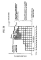
- the distribution block 13 further adds the trap quantity M hcad(n) distributed to each of the temperature zones to the occlusion quantity Q of hydrocarbon acquired by a previous operation period. Quantities of hydrocarbons occluded in each of the temperature zones are labeled Q( n ) by use of the same ordinal numbers "n" as those of the trap quantity M hcad(n) .
- Figs. 7A and 7B show a distribution image of the occlusion quantities Q(n) added with the distributed occluding quantity M hcad(n) .
- Fig. 7A is a distribution image to which the trap quantity M hcad(1) distributed at the distribution ratio shown in Fig. 6A is added.
- Fig. 7B is a distribution image to which the trap quantity M hcad(1) distributed at the distribution ratio shown in Fig. 6B is added.
- Fig. 7B shows a state in which the trap quantity M hcad(n) is added to only temperature zones to become distribution targets.
- the desorption quantity calculation block 14 calculates a quantity M hcde [g/sec] of hydrocarbon desorbed from the occluding catalyst 2 per unit time.
- the desorption quantity M hcde is determined according to the first catalyst temperature T 1 and the characteristic of the occluding catalyst 2. For instance, settings shown in Fig. 5F are made in light of the desorption characteristic of the occluding catalyst 2, such as that shown in Fig. 3 .
- the desorption quantity M hcde is set to a predetermined desorption quantity M hcde1 .
- the first catalyst temperature T 1 is the predetermined temperature T 01 or more and under the regeneration temperature T 03 , settings are made in such a way that the desorption quantity M hcde increases in a range that is the predetermined desorption quantity M hcde1 or less as the first catalyst temperature T 1 increases.
- the subtraction block 15 subtracts the desorption quantity M hcde calculated by the desorption quantity calculation block 14 from the occlusion quantities Q (n) added with the trap quantity M hcad(n) by means of the distribution block 13.
- the desorption quantity M hcde is subtracted, in an increasing sequence of a boiling point, from each of the trap quantities on the low boiling point side among the occlusion quantities Q (n) .
- the subtraction technique is now described by reference to Fig. 8A .
- the subtraction block 15 subjects a temperature zone, which is to become a subtraction target, to subtraction in sequence from a low temperature zone.
- the temperature zone that is to become a subtraction target is a temperature zone that is less than the first catalyst temperature T 1 (a temperature zone that is located on a lower boiling point side as compared with the temperature zone corresponding to the first catalyst temperature T 1 ).
- hydrocarbons having boiling points belonging to the temperature zone that is the first catalyst temperature T 1 or more are deemed to still remain trapped in the occluding catalyst 2 without desorption.
- the subtraction block 15 subtracts the hydrocarbons for the description quantity M hcde from the occlusion quantities Q (n) for the hydrocarbons occluded in the respective temperature zones on the lower boiling point side, thereby calculating an occlusion quantity Q that is a total of the occlusion quantities Q (n) .
- An image of distribution of the occlusion quantities Q (n) acquired after subtraction, such as those shown in Figs. 8B and 8C reflects on a boiling point distribution in which quantities of hydrocarbons actually occluded in the occluding catalyst 2 are classified according to a boiling point. The total area of the entire occlusion quantities corresponds to the occlusion quantity Q.
- the method for calculating the occlusion quantity Q is generalized as follows.
- a term ⁇ T [sec] is a period for calculating the trap quantity M hcad and the desorption quantity M hcde .
- the determination block 16 controls setting or clearing of a purge control flag.
- the purge control block 17 makes a reference to the thus-set purge request flag.
- the purge control block 17 performs purge control, thereby forcefully desorbing and eliminating the hydrocarbon occluded in the occlusion catalyst 2. Requirements for commencing purge control are mentioned below.
- the purge control block 17 commences purge control, thereby regulating the exhaust temperature in such a way that the catalyst temperature of the occlusion catalyst 2 is maintained at the regeneration temperature T c .
- Commencement requirements pertaining to the second catalyst temperature T 2 and the vehicle speed V are requirements for determining whether or not the current state is an operating state that allows an increase in exhaust temperature which would be caused by purge control.
- a specific technique for regulating an exhaust temperature under purge control is arbitrary.
- a conceivable technique includes changing of; for instance, a fuel-air ratio, an intake air quantity, a fuel injection quantity, fuel injection timing, a post injection quantity, and the like, that are relevant to combustion reaction occurred in the combustion chambers of the engine 1.
- a requirement to complete purge control is that the first catalyst temperature T 1 becomes continually equal to or higher than the regeneration temperature T c for a predetermined period of time.
- the predetermined period of time is set to; for instance, several minutes.
- Preferable completion requirements are that hydrocarbon is deemed to be desorbed and purified substantially completely from the occlusion catalyst 2.
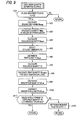
- Fig. 9 is a flowchart showing example occlusion quantity estimation control.
- Fig. 10 is a flowchart showing example purge control. Processing pertaining to these flows are concurrently in progress, thereby attempting to synchronize control specifics by way of the two types of flags F 1 and F 2 .
- a calculation period of an occlusion quantity estimation control flow is ⁇ T.
- the estimation control block 11 performs occlusion quantity estimation control.
- the estimation control block 11 determines a state of the purge implement flag F 2 .
- processing pertaining to the flow ends as it does, whereby occlusion quantity estimation control is suspended.
- the trap quantity calculation block 12 performs control operation pertaining to steps A20 to A40.
- step A20 the engine discharge M hceng is calculated by means of Equation 3.
- step A30 the hydrocarbon inflow quantity M hcin is calculated by means of Equation 2.
- step A40 the trap quantity M hcad is calculated by means of Equation 1.
- the distribution block 13 performs control processing pertaining to steps A50 to 70.
- step A50 either the first catalyst temperature T 1 or the second catalyst temperature T 2 , whichever is higher, is selected.
- the minimum value of the temperature zone that is to become a distribution target of the trap quantity M hcad is determined by the thus-selected temperature.
- step A60 the trap quantity M hcad is distributed to each of the temperature zones as shown in Figs. 6A and 6B .
- step A70 the trap quantity M hcad(n) distributed to each of the temperature zones is added to the hydrocarbon occlusion quantity Q acquired so far in the previous operation period, as shown in Figs. 7A and 7B .
- step A80 the desorption quantity calculation block 14 calculates the desorption quantity M hcde according to the first catalyst temperature T 1 .
- the subtraction block 15 performs processing pertaining to subsequent steps A90 and A100.
- step A90 temperature zones located on a lower boiling point side with reference to the temperature zones of the first catalyst temperature T 1 or more are determined as subtraction targets. Specifically, the maximum value for zones that become subtraction targets is determined by the first catalyst temperature T 1 .
- step A100 the desorption quantity M hcde is subtracted from the temperature zones located on the lower boiling point side in increasing sequence from a low boiling point.
- a distribution of occlusion quantities Q (n) of the hydrocarbon actually occluded in the occluding catalyst 2 for respective temperature zones is thereby acquired.
- the occlusion quantity Q is calculated by addition of all of the occlusion quantities Q (n) for respective temperature zones.
- step A110 the determination block 16 determines whether or not the occlusion quantity Q is a predetermined threshold value Q TH or less.
- Q ⁇ Q TH processing pertaining to the flow ends as it does.
- the purge control block 17 performs purge control.
- step B10 a state of the purge request flag F 1 is determined.
- step B20 remaining initiation requirements for purge control are determined.
- the second catalyst temperature T 2 is a predetermined temperature or less and when the vehicle speed V is a predetermined speed or higher, purge control initiation requirements are fulfilled, and processing proceeds to step B30.
- the initiation requirements are not fulfilled, processing pertaining to the flow ends as it does.
- the purge implement flag F 2 acts to let the estimation control block 11 suspend performance of occlusion quantity estimation control.
- step B40 purge control is performed.
- the temperature of emissions flowing into the occluding catalyst 2 is thereby regulated, so that the first catalyst temperature T 1 is maintained at the regeneration temperature T c .
- step B50 completion requirements for purge control are determined.
- the first catalyst temperature T 1 is continually equal to or higher than the regeneration temperature T c for a predetermined period of time
- completion requirements for purge control are fulfilled, whereupon processing proceeds to step B60.
- processing proceeds to step B50, and purge control is continually performed until the completion requirements are fulfilled.
- the trap quantity M hcad is distributed solely to temperature zones that are higher than either the first catalyst temperature T 1 or the second catalyst temperature T 2 , whichever is higher.
- the trap quantity can be distributed by eliminating the hydrocarbons having low boiling points that should not have flowed into the occluding catalyst 2 or the hydrocarbons having low boiling points that should not be trapped by the occluding catalyst 2, whereby occurrence of miscalculation is prevented. Consequently, it is possible to accurately ascertain the occlusion quantity Q of hydrocarbons having high boiling points.
- control is implemented by means of a simple configuration based on the catalyst temperature of the occluding catalyst 2 and the catalyst temperature of the oxidation catalyst 3, so that the accuracy of estimation of an occlusion quantity can be enhanced without involvement of an increase in system cost.
- the occluding catalyst 2 is situated at a downstream position on the exhaust passageway 6 with respect to the oxidation catalyst 3. Therefore, the first catalyst temperature T 1 is likely to be lower than the second catalyst temperature T 2 . Temperature zones that are to become distribution targets correspond to temperature zones on a high temperature boiling point side with reference to the first catalyst temperature T 1 . Therefore, it is possible to make a comparatively small estimate of the quantity of trapped hydrocarbon on the low boiling point side. Such a control configuration can also be said to contribute to accurate estimation of the trap quantity M hcad and the occlusion quantity Q.
- the distribution block 13 estimates a distribution of presence of hydrocarbons trapped by the occluding catalyst 2 for each type of hydrocarbon by means of taking as a model the distribution model imitating a boiling point distribution of hydrocarbons in emissions.
- a model that takes as a model the boiling point distribution of hydrocarbons in emissions flowing into the occluding catalyst 2 is taken as a distribution model of the trap quantity M hcad .
- the desorption quantity M hcde is subtracted solely from the temperature zones on the lower boiling point side than from the temperature zones corresponding to the first catalyst temperature T 1 . Therefore, the quantities of hydrocarbons having high boiling points that should not originally be desorbed are not subtracted, and the occlusion quantity Q of hydrocarbons having high boiling points can be maintained from a calculation viewpoint, so that underestimation of the occlusion quantity Q can be inhibited.
- purge control is performed according to an accurate estimation of the occlusion quantity Q, it is possible to minimize an increase in fuel consumption while deterioration of the occluding catalyst 2 is prevented, and also to enhance efficiency of emission purification.
- the present invention can be implemented in various forms without departing the gist of the invention.
- the respective configurations of the embodiment can be adopted or rejected, as required, or used in combination if necessary.
- the occluding catalyst 2 has exemplified the occluding catalyst 2 as a catalyst unit having a hydrocarbon occluding layer and a precious metal catalyst layer.
- the precious metal catalyst layer is not an indispensable element. The minimum requirement is that a layer should trap and desorb hydrocarbons included in emission and trap and desorb a plurality of types of hydrocarbons having different boiling points.
- a catalyst configuration of a specific exhaust system is not confined to the foregoing embodiment.
- the oxidation catalyst 3 can also be omitted, or the layout of the catalyst on the exhaust passageway 6 can also be changed. If the oxidation catalyst 3 is omitted, the second temperature sensor 5 will become unnecessary. Further, the upstream slip coefficient K OXI will become unnecessary for calculation of the quantity M hcin of inflow hydrocarbon.
- another catalyst or filter may also be interposed at a position on the exhaust passageway 6 between the occluding catalyst 2 and the oxidation catalyst 3.
- a nitrogen oxide occluding catalyst is interposed between the occluding catalyst 2 and the oxidation catalyst 3, it is preferable to add to calculation of the engine discharge M hceng a quantity of hydrocarbon serving as an additive used for reducing reaction in the nitrogen oxide occluding catalyst.
- a quantity of hydrocarbon serving as an additive used for reducing reaction in the nitrogen oxide occluding catalyst.
- a conceivable way is to set a fuel-air ratio correction coefficient K NOP according to a state of a fuel-air ratio, and a right side of Equation 3 is multiplied by the coefficient, thereby correcting the engine discharge M hceng .
- the operation makes it possible to accurately ascertain the quantity of hydrocarbon flowing into the occluding catalyst 2, whereby the precision of assumption of the hydrocarbon occlusion quantity Q can be further enhanced.
- the embodiment has illustrated a simplified illustration of a distribution model of boiling points of hydrocarbons included in emissions and a simplified illustration of a distribution model of the trap quantity M hcad .
- Specific shapes of the models are arbitrary.
- the distribution model of boiling points and the distribution model of the trap quantity M hcad are considered to be set, as required, according to the property of a fuel used in the engine 1, a structure and shape of an exhaust system, a configuration of the catalyst, and the like.
- models that have previously been set by means of tests, or the like may also be used for the distribution model of boiling points of hydrocarbons and the distribution model of the trap quantity M hcad .
- Classification of types of hydrocarbons performed during estimation and calculation of the occlusion quantity is based on boiling points in the embodiment. However, classification may also be performed according to the number of carbons or according to a molecular structure instead. Specifically, conceivable classification is based on a physical quantity correlating with boiling points. So long as the quantity Q of hydrocarbons occluded in the occluding catalyst 2 is classified at least by use of a physical quantity correlating with boiling points, control analogous to that described in connection with the embodiment is implemented, so that accuracy of estimation of the occlusion quantity can be enhanced.
- the first temperature sensor 4 provided downstream of the occluding catalyst 2 detects the first catalyst temperature T 1
- the second temperature sensor 5 provided downstream of the oxidation catalyst 3 detects the second catalyst temperature T 2 .
- a technique for ascertaining the first catalyst temperature T 1 and the second catalyst temperature T 2 is not limited to that mentioned above.
- another catalyst temperature may also be estimated from one catalyst temperature.
- the technique for calculating engine torque is not limited to the thus-exemplified technique.
- a combustion pressure sensor for detecting combustion pressure in cylinders may also be used.
- a torque estimation value calculated by an unillustrated engine ECU may also be utilized.
- the disclosed exhaust emission control device of an internal combustion engine can be applied to both a diesel engine and a gasoline engine.
Landscapes
- Engineering & Computer Science (AREA)
- Chemical & Material Sciences (AREA)
- Combustion & Propulsion (AREA)
- Mechanical Engineering (AREA)
- General Engineering & Computer Science (AREA)
- Chemical Kinetics & Catalysis (AREA)
- Materials Engineering (AREA)
- Health & Medical Sciences (AREA)
- Toxicology (AREA)
- Exhaust Gas After Treatment (AREA)
- Combined Controls Of Internal Combustion Engines (AREA)
Applications Claiming Priority (1)
| Application Number | Priority Date | Filing Date | Title |
|---|---|---|---|
| JP2010026667A JP5348001B2 (ja) | 2010-02-09 | 2010-02-09 | 内燃機関の排気浄化装置 |
Publications (3)
| Publication Number | Publication Date |
|---|---|
| EP2354504A2 true EP2354504A2 (de) | 2011-08-10 |
| EP2354504A3 EP2354504A3 (de) | 2014-09-03 |
| EP2354504B1 EP2354504B1 (de) | 2016-09-07 |
Family
ID=43868739
Family Applications (1)
| Application Number | Title | Priority Date | Filing Date |
|---|---|---|---|
| EP11150699.4A Not-in-force EP2354504B1 (de) | 2010-02-09 | 2011-01-12 | Vorrichtung zur Regelung der Abgasemission für einen Verbrennungsmotor |
Country Status (2)
| Country | Link |
|---|---|
| EP (1) | EP2354504B1 (de) |
| JP (1) | JP5348001B2 (de) |
Cited By (1)
| Publication number | Priority date | Publication date | Assignee | Title |
|---|---|---|---|---|
| JP2015519518A (ja) * | 2012-06-13 | 2015-07-09 | マック トラックス インコーポレイテッド | 排気後処理システムの部品を監視する方法、排気後処理システム、及び排気後処理システムの制御装置 |
Citations (1)
| Publication number | Priority date | Publication date | Assignee | Title |
|---|---|---|---|---|
| JP2005240726A (ja) | 2004-02-27 | 2005-09-08 | Nissan Motor Co Ltd | 内燃機関の排気浄化装置 |
Family Cites Families (8)
| Publication number | Priority date | Publication date | Assignee | Title |
|---|---|---|---|---|
| JPH0627502B2 (ja) * | 1986-01-27 | 1994-04-13 | トヨタ自動車株式会社 | 排気浄化装置 |
| JP3264522B2 (ja) * | 1991-09-06 | 2002-03-11 | 株式会社豊田中央研究所 | 炭化水素成分トラッパ装置,蒸発燃料吸収装置及び排気ガス浄化装置 |
| JPH0693846A (ja) * | 1992-09-14 | 1994-04-05 | Nissan Motor Co Ltd | 内燃機関の排気浄化装置 |
| JP3712314B2 (ja) * | 1997-08-08 | 2005-11-02 | 株式会社日本自動車部品総合研究所 | 排気浄化用触媒の炭化水素吸着量検出装置 |
| JP2001159360A (ja) * | 1999-12-02 | 2001-06-12 | Nissan Motor Co Ltd | ディーゼルエンジンの燃料制御装置 |
| JP2004108320A (ja) * | 2002-09-20 | 2004-04-08 | Isuzu Motors Ltd | 排気ガス浄化方法及びそのシステム |
| JP5608962B2 (ja) * | 2008-07-25 | 2014-10-22 | いすゞ自動車株式会社 | 排気ガス浄化システム |
| US8375701B2 (en) * | 2008-07-30 | 2013-02-19 | Ford Global Technologies, Llc | Hydrocarbon retaining and purging system |
-
2010
- 2010-02-09 JP JP2010026667A patent/JP5348001B2/ja not_active Expired - Fee Related
-
2011
- 2011-01-12 EP EP11150699.4A patent/EP2354504B1/de not_active Not-in-force
Patent Citations (1)
| Publication number | Priority date | Publication date | Assignee | Title |
|---|---|---|---|---|
| JP2005240726A (ja) | 2004-02-27 | 2005-09-08 | Nissan Motor Co Ltd | 内燃機関の排気浄化装置 |
Cited By (1)
| Publication number | Priority date | Publication date | Assignee | Title |
|---|---|---|---|---|
| JP2015519518A (ja) * | 2012-06-13 | 2015-07-09 | マック トラックス インコーポレイテッド | 排気後処理システムの部品を監視する方法、排気後処理システム、及び排気後処理システムの制御装置 |
Also Published As
| Publication number | Publication date |
|---|---|
| JP2011163208A (ja) | 2011-08-25 |
| EP2354504B1 (de) | 2016-09-07 |
| JP5348001B2 (ja) | 2013-11-20 |
| EP2354504A3 (de) | 2014-09-03 |
Similar Documents
| Publication | Publication Date | Title |
|---|---|---|
| US6990800B2 (en) | Diesel aftertreatment systems | |
| EP0972927B1 (de) | Abgasreinigungssystem und- verfahren für eine Brennkraftmaschine | |
| US10161845B2 (en) | Method for monitoring a particulate filter | |
| JP4962348B2 (ja) | 内燃機関の排気浄化装置及び浄化方法 | |
| US6990854B2 (en) | Active lean NOx catalyst diagnostics | |
| US6826902B2 (en) | Method and apparatus for estimating oxygen storage capacity and stored NOx in a lean NOx trap (LNT) | |
| US20110153260A1 (en) | Method for diagnosing a catalytic device of an engine exhaust gas after-treatment system | |
| CN109690043B (zh) | 内燃机的控制装置以及控制方法 | |
| WO2008108499A1 (ja) | NOx触媒の劣化診断装置 | |
| JP5007845B2 (ja) | 内燃機関の排気浄化装置 | |
| US8820048B2 (en) | System and method for detecting pollution by poisonous material for air exhauster of vehicle | |
| JP2003083042A (ja) | 内燃機関の診断装置 | |
| EP3382172B1 (de) | Vorrichtung zur diagnose von anomalien für eine abgasreinigungsvorrichtung | |
| EP3401522B1 (de) | Abgassteuerungssystem für einen verbrennungsmotor und verfahren zur steuerung des abgassteuerungssystems für einen verbrennungsmotor | |
| US20170074137A1 (en) | Method of operating an aftertreatment system of an internal combustion engine | |
| EP3267002B1 (de) | Steuerungsvorrichtung für verbrennungsmotor | |
| JP6248978B2 (ja) | 内燃機関の制御装置 | |
| EP2354504B1 (de) | Vorrichtung zur Regelung der Abgasemission für einen Verbrennungsmotor | |
| KR101480644B1 (ko) | 린 녹스 트랩 촉매의 열화 감지 방법 | |
| JP4193790B2 (ja) | 内燃機関の排気浄化装置 | |
| EP3431728B1 (de) | System zur diagnose von anomalien für eine abgasreinigungsvorrichtung | |
| JP2017129037A (ja) | NOx吸蔵還元型触媒の異常診断装置 | |
| JP7124771B2 (ja) | ラムダセンサーの応答性診断方法、及び排気浄化システム | |
| JP2004132181A (ja) | Hc濃度予測方法およびhc吸着触媒の劣化診断装置 | |
| JP2000213339A (ja) | 内燃機関の排気浄化装置 |
Legal Events
| Date | Code | Title | Description |
|---|---|---|---|
| PUAI | Public reference made under article 153(3) epc to a published international application that has entered the european phase |
Free format text: ORIGINAL CODE: 0009012 |
|
| 17P | Request for examination filed |
Effective date: 20110209 |
|
| AK | Designated contracting states |
Kind code of ref document: A2 Designated state(s): AL AT BE BG CH CY CZ DE DK EE ES FI FR GB GR HR HU IE IS IT LI LT LU LV MC MK MT NL NO PL PT RO RS SE SI SK SM TR |
|
| AX | Request for extension of the european patent |
Extension state: BA ME |
|
| PUAL | Search report despatched |
Free format text: ORIGINAL CODE: 0009013 |
|
| AK | Designated contracting states |
Kind code of ref document: A3 Designated state(s): AL AT BE BG CH CY CZ DE DK EE ES FI FR GB GR HR HU IE IS IT LI LT LU LV MC MK MT NL NO PL PT RO RS SE SI SK SM TR |
|
| AX | Request for extension of the european patent |
Extension state: BA ME |
|
| RIC1 | Information provided on ipc code assigned before grant |
Ipc: F01N 3/08 20060101ALI20140729BHEP Ipc: F01N 3/10 20060101ALI20140729BHEP Ipc: F02D 41/02 20060101AFI20140729BHEP |
|
| 17Q | First examination report despatched |
Effective date: 20150720 |
|
| GRAP | Despatch of communication of intention to grant a patent |
Free format text: ORIGINAL CODE: EPIDOSNIGR1 |
|
| INTG | Intention to grant announced |
Effective date: 20160329 |
|
| GRAS | Grant fee paid |
Free format text: ORIGINAL CODE: EPIDOSNIGR3 |
|
| GRAA | (expected) grant |
Free format text: ORIGINAL CODE: 0009210 |
|
| AK | Designated contracting states |
Kind code of ref document: B1 Designated state(s): AL AT BE BG CH CY CZ DE DK EE ES FI FR GB GR HR HU IE IS IT LI LT LU LV MC MK MT NL NO PL PT RO RS SE SI SK SM TR |
|
| REG | Reference to a national code |
Ref country code: GB Ref legal event code: FG4D |
|
| REG | Reference to a national code |
Ref country code: CH Ref legal event code: EP |
|
| REG | Reference to a national code |
Ref country code: IE Ref legal event code: FG4D |
|
| REG | Reference to a national code |
Ref country code: AT Ref legal event code: REF Ref document number: 827103 Country of ref document: AT Kind code of ref document: T Effective date: 20161015 |
|
| REG | Reference to a national code |
Ref country code: DE Ref legal event code: R096 Ref document number: 602011030011 Country of ref document: DE |
|
| REG | Reference to a national code |
Ref country code: LT Ref legal event code: MG4D |
|
| REG | Reference to a national code |
Ref country code: NL Ref legal event code: MP Effective date: 20160907 |
|
| REG | Reference to a national code |
Ref country code: FR Ref legal event code: PLFP Year of fee payment: 7 |
|
| PG25 | Lapsed in a contracting state [announced via postgrant information from national office to epo] |
Ref country code: NO Free format text: LAPSE BECAUSE OF FAILURE TO SUBMIT A TRANSLATION OF THE DESCRIPTION OR TO PAY THE FEE WITHIN THE PRESCRIBED TIME-LIMIT Effective date: 20161207 Ref country code: LT Free format text: LAPSE BECAUSE OF FAILURE TO SUBMIT A TRANSLATION OF THE DESCRIPTION OR TO PAY THE FEE WITHIN THE PRESCRIBED TIME-LIMIT Effective date: 20160907 Ref country code: HR Free format text: LAPSE BECAUSE OF FAILURE TO SUBMIT A TRANSLATION OF THE DESCRIPTION OR TO PAY THE FEE WITHIN THE PRESCRIBED TIME-LIMIT Effective date: 20160907 Ref country code: RS Free format text: LAPSE BECAUSE OF FAILURE TO SUBMIT A TRANSLATION OF THE DESCRIPTION OR TO PAY THE FEE WITHIN THE PRESCRIBED TIME-LIMIT Effective date: 20160907 Ref country code: FI Free format text: LAPSE BECAUSE OF FAILURE TO SUBMIT A TRANSLATION OF THE DESCRIPTION OR TO PAY THE FEE WITHIN THE PRESCRIBED TIME-LIMIT Effective date: 20160907 |
|
| REG | Reference to a national code |
Ref country code: AT Ref legal event code: MK05 Ref document number: 827103 Country of ref document: AT Kind code of ref document: T Effective date: 20160907 |
|
| PG25 | Lapsed in a contracting state [announced via postgrant information from national office to epo] |
Ref country code: NL Free format text: LAPSE BECAUSE OF FAILURE TO SUBMIT A TRANSLATION OF THE DESCRIPTION OR TO PAY THE FEE WITHIN THE PRESCRIBED TIME-LIMIT Effective date: 20160907 Ref country code: LV Free format text: LAPSE BECAUSE OF FAILURE TO SUBMIT A TRANSLATION OF THE DESCRIPTION OR TO PAY THE FEE WITHIN THE PRESCRIBED TIME-LIMIT Effective date: 20160907 Ref country code: SE Free format text: LAPSE BECAUSE OF FAILURE TO SUBMIT A TRANSLATION OF THE DESCRIPTION OR TO PAY THE FEE WITHIN THE PRESCRIBED TIME-LIMIT Effective date: 20160907 Ref country code: ES Free format text: LAPSE BECAUSE OF FAILURE TO SUBMIT A TRANSLATION OF THE DESCRIPTION OR TO PAY THE FEE WITHIN THE PRESCRIBED TIME-LIMIT Effective date: 20160907 Ref country code: GR Free format text: LAPSE BECAUSE OF FAILURE TO SUBMIT A TRANSLATION OF THE DESCRIPTION OR TO PAY THE FEE WITHIN THE PRESCRIBED TIME-LIMIT Effective date: 20161208 |
|
| PG25 | Lapsed in a contracting state [announced via postgrant information from national office to epo] |
Ref country code: EE Free format text: LAPSE BECAUSE OF FAILURE TO SUBMIT A TRANSLATION OF THE DESCRIPTION OR TO PAY THE FEE WITHIN THE PRESCRIBED TIME-LIMIT Effective date: 20160907 Ref country code: RO Free format text: LAPSE BECAUSE OF FAILURE TO SUBMIT A TRANSLATION OF THE DESCRIPTION OR TO PAY THE FEE WITHIN THE PRESCRIBED TIME-LIMIT Effective date: 20160907 |
|
| PG25 | Lapsed in a contracting state [announced via postgrant information from national office to epo] |
Ref country code: SK Free format text: LAPSE BECAUSE OF FAILURE TO SUBMIT A TRANSLATION OF THE DESCRIPTION OR TO PAY THE FEE WITHIN THE PRESCRIBED TIME-LIMIT Effective date: 20160907 Ref country code: PT Free format text: LAPSE BECAUSE OF FAILURE TO SUBMIT A TRANSLATION OF THE DESCRIPTION OR TO PAY THE FEE WITHIN THE PRESCRIBED TIME-LIMIT Effective date: 20170109 Ref country code: PL Free format text: LAPSE BECAUSE OF FAILURE TO SUBMIT A TRANSLATION OF THE DESCRIPTION OR TO PAY THE FEE WITHIN THE PRESCRIBED TIME-LIMIT Effective date: 20160907 Ref country code: BE Free format text: LAPSE BECAUSE OF FAILURE TO SUBMIT A TRANSLATION OF THE DESCRIPTION OR TO PAY THE FEE WITHIN THE PRESCRIBED TIME-LIMIT Effective date: 20160907 Ref country code: AT Free format text: LAPSE BECAUSE OF FAILURE TO SUBMIT A TRANSLATION OF THE DESCRIPTION OR TO PAY THE FEE WITHIN THE PRESCRIBED TIME-LIMIT Effective date: 20160907 Ref country code: CZ Free format text: LAPSE BECAUSE OF FAILURE TO SUBMIT A TRANSLATION OF THE DESCRIPTION OR TO PAY THE FEE WITHIN THE PRESCRIBED TIME-LIMIT Effective date: 20160907 Ref country code: IS Free format text: LAPSE BECAUSE OF FAILURE TO SUBMIT A TRANSLATION OF THE DESCRIPTION OR TO PAY THE FEE WITHIN THE PRESCRIBED TIME-LIMIT Effective date: 20170107 Ref country code: BG Free format text: LAPSE BECAUSE OF FAILURE TO SUBMIT A TRANSLATION OF THE DESCRIPTION OR TO PAY THE FEE WITHIN THE PRESCRIBED TIME-LIMIT Effective date: 20161207 Ref country code: SM Free format text: LAPSE BECAUSE OF FAILURE TO SUBMIT A TRANSLATION OF THE DESCRIPTION OR TO PAY THE FEE WITHIN THE PRESCRIBED TIME-LIMIT Effective date: 20160907 |
|
| REG | Reference to a national code |
Ref country code: DE Ref legal event code: R097 Ref document number: 602011030011 Country of ref document: DE |
|
| PG25 | Lapsed in a contracting state [announced via postgrant information from national office to epo] |
Ref country code: IT Free format text: LAPSE BECAUSE OF FAILURE TO SUBMIT A TRANSLATION OF THE DESCRIPTION OR TO PAY THE FEE WITHIN THE PRESCRIBED TIME-LIMIT Effective date: 20160907 |
|
| PLBE | No opposition filed within time limit |
Free format text: ORIGINAL CODE: 0009261 |
|
| STAA | Information on the status of an ep patent application or granted ep patent |
Free format text: STATUS: NO OPPOSITION FILED WITHIN TIME LIMIT |
|
| PG25 | Lapsed in a contracting state [announced via postgrant information from national office to epo] |
Ref country code: DK Free format text: LAPSE BECAUSE OF FAILURE TO SUBMIT A TRANSLATION OF THE DESCRIPTION OR TO PAY THE FEE WITHIN THE PRESCRIBED TIME-LIMIT Effective date: 20160907 |
|
| 26N | No opposition filed |
Effective date: 20170608 |
|
| PG25 | Lapsed in a contracting state [announced via postgrant information from national office to epo] |
Ref country code: SI Free format text: LAPSE BECAUSE OF FAILURE TO SUBMIT A TRANSLATION OF THE DESCRIPTION OR TO PAY THE FEE WITHIN THE PRESCRIBED TIME-LIMIT Effective date: 20160907 |
|
| REG | Reference to a national code |
Ref country code: CH Ref legal event code: PL |
|
| GBPC | Gb: european patent ceased through non-payment of renewal fee |
Effective date: 20170112 |
|
| PG25 | Lapsed in a contracting state [announced via postgrant information from national office to epo] |
Ref country code: MC Free format text: LAPSE BECAUSE OF FAILURE TO SUBMIT A TRANSLATION OF THE DESCRIPTION OR TO PAY THE FEE WITHIN THE PRESCRIBED TIME-LIMIT Effective date: 20160907 |
|
| PG25 | Lapsed in a contracting state [announced via postgrant information from national office to epo] |
Ref country code: CH Free format text: LAPSE BECAUSE OF NON-PAYMENT OF DUE FEES Effective date: 20170131 Ref country code: LI Free format text: LAPSE BECAUSE OF NON-PAYMENT OF DUE FEES Effective date: 20170131 |
|
| REG | Reference to a national code |
Ref country code: IE Ref legal event code: MM4A |
|
| PG25 | Lapsed in a contracting state [announced via postgrant information from national office to epo] |
Ref country code: GB Free format text: LAPSE BECAUSE OF NON-PAYMENT OF DUE FEES Effective date: 20170112 Ref country code: LU Free format text: LAPSE BECAUSE OF NON-PAYMENT OF DUE FEES Effective date: 20170112 |
|
| REG | Reference to a national code |
Ref country code: FR Ref legal event code: PLFP Year of fee payment: 8 |
|
| PG25 | Lapsed in a contracting state [announced via postgrant information from national office to epo] |
Ref country code: IE Free format text: LAPSE BECAUSE OF NON-PAYMENT OF DUE FEES Effective date: 20170112 |
|
| PG25 | Lapsed in a contracting state [announced via postgrant information from national office to epo] |
Ref country code: MT Free format text: LAPSE BECAUSE OF NON-PAYMENT OF DUE FEES Effective date: 20170112 |
|
| PG25 | Lapsed in a contracting state [announced via postgrant information from national office to epo] |
Ref country code: AL Free format text: LAPSE BECAUSE OF FAILURE TO SUBMIT A TRANSLATION OF THE DESCRIPTION OR TO PAY THE FEE WITHIN THE PRESCRIBED TIME-LIMIT Effective date: 20160907 |
|
| PGFP | Annual fee paid to national office [announced via postgrant information from national office to epo] |
Ref country code: FR Payment date: 20181213 Year of fee payment: 9 |
|
| PGFP | Annual fee paid to national office [announced via postgrant information from national office to epo] |
Ref country code: DE Payment date: 20190102 Year of fee payment: 9 |
|
| PG25 | Lapsed in a contracting state [announced via postgrant information from national office to epo] |
Ref country code: HU Free format text: LAPSE BECAUSE OF FAILURE TO SUBMIT A TRANSLATION OF THE DESCRIPTION OR TO PAY THE FEE WITHIN THE PRESCRIBED TIME-LIMIT; INVALID AB INITIO Effective date: 20110112 |
|
| PG25 | Lapsed in a contracting state [announced via postgrant information from national office to epo] |
Ref country code: CY Free format text: LAPSE BECAUSE OF NON-PAYMENT OF DUE FEES Effective date: 20160907 |
|
| PG25 | Lapsed in a contracting state [announced via postgrant information from national office to epo] |
Ref country code: MK Free format text: LAPSE BECAUSE OF FAILURE TO SUBMIT A TRANSLATION OF THE DESCRIPTION OR TO PAY THE FEE WITHIN THE PRESCRIBED TIME-LIMIT Effective date: 20160907 |
|
| PG25 | Lapsed in a contracting state [announced via postgrant information from national office to epo] |
Ref country code: TR Free format text: LAPSE BECAUSE OF FAILURE TO SUBMIT A TRANSLATION OF THE DESCRIPTION OR TO PAY THE FEE WITHIN THE PRESCRIBED TIME-LIMIT Effective date: 20160907 |
|
| REG | Reference to a national code |
Ref country code: DE Ref legal event code: R119 Ref document number: 602011030011 Country of ref document: DE |
|
| PG25 | Lapsed in a contracting state [announced via postgrant information from national office to epo] |
Ref country code: DE Free format text: LAPSE BECAUSE OF NON-PAYMENT OF DUE FEES Effective date: 20200801 Ref country code: FR Free format text: LAPSE BECAUSE OF NON-PAYMENT OF DUE FEES Effective date: 20200131 |