EP2353943A1 - Stop device for an automobile - Google Patents
Stop device for an automobile Download PDFInfo
- Publication number
- EP2353943A1 EP2353943A1 EP11305053A EP11305053A EP2353943A1 EP 2353943 A1 EP2353943 A1 EP 2353943A1 EP 11305053 A EP11305053 A EP 11305053A EP 11305053 A EP11305053 A EP 11305053A EP 2353943 A1 EP2353943 A1 EP 2353943A1
- Authority
- EP
- European Patent Office
- Prior art keywords
- abutment
- support
- stop
- damper
- vertical
- Prior art date
- Legal status (The legal status is an assumption and is not a legal conclusion. Google has not performed a legal analysis and makes no representation as to the accuracy of the status listed.)
- Granted
Links
Images


Classifications
-
- B—PERFORMING OPERATIONS; TRANSPORTING
- B60—VEHICLES IN GENERAL
- B60R—VEHICLES, VEHICLE FITTINGS, OR VEHICLE PARTS, NOT OTHERWISE PROVIDED FOR
- B60R19/00—Wheel guards; Radiator guards, e.g. grilles; Obstruction removers; Fittings damping bouncing force in collisions
- B60R19/02—Bumpers, i.e. impact receiving or absorbing members for protecting vehicles or fending off blows from other vehicles or objects
- B60R19/04—Bumpers, i.e. impact receiving or absorbing members for protecting vehicles or fending off blows from other vehicles or objects formed from more than one section in a side-by-side arrangement
- B60R19/16—Bumpers, i.e. impact receiving or absorbing members for protecting vehicles or fending off blows from other vehicles or objects formed from more than one section in a side-by-side arrangement having deflecting members, e.g. rollers, balls
-
- B—PERFORMING OPERATIONS; TRANSPORTING
- B60—VEHICLES IN GENERAL
- B60R—VEHICLES, VEHICLE FITTINGS, OR VEHICLE PARTS, NOT OTHERWISE PROVIDED FOR
- B60R19/00—Wheel guards; Radiator guards, e.g. grilles; Obstruction removers; Fittings damping bouncing force in collisions
- B60R19/02—Bumpers, i.e. impact receiving or absorbing members for protecting vehicles or fending off blows from other vehicles or objects
- B60R2019/026—Buffers, i.e. bumpers of limited extent
Definitions
- the present invention relates to a stop device for a motor vehicle, of the type described in the preamble of claim 1.
- the document EP-A-1792785 discloses a stop device of the aforementioned type.
- the linear mobility of the abutment relative to the damper makes it possible to modify the pressure exerted on the shock absorber during the docking of the vehicle against the dock.
- the abutment comprises a body of revolution with a curved surface of revolution. Thanks to the body of revolution, the stop can roll along the vertical surface of the dock during loading or unloading of the vehicle and ensure a permanent contact between the vehicle and the dock.
- the curved surface allows a docking of the abutment against the platform if the rear face of the vehicle is oriented parallel to the vertical surface of the platform, but also if the angle between the rear face of the vehicle and the vertical surface is, within a certain limit , different from 0 °. If this angle is not 0 °, the body of revolution will not come into contact with the vertical surface at its maximum diameter, but at a different location than its length.
- the stop engages the vertical surface only by a point.
- the present invention aims to improve the contact between the vehicle and the dock during loading or unloading of the vehicle, while maintaining a flexibility of angular orientation of the abutment during docking.
- the invention relates to a stop device of the aforementioned type characterized by the characterizing part of claim 1.
- the invention further relates to a motor vehicle, of the heavy truck type, comprising a stop device as defined above.
- the stop device 2 extends in a horizontal plane which comprises the longitudinal axis AA and the transverse axis BB.
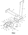
- the arrow 4 is parallel to the axis AA and shows the forward direction of the stop device 2.
- the abutment device 2 comprises a stop assembly 6, a support leg 8 and an abutment 10.
- the leg 8 and the abutment 10 are frame members, that is to say that they are attached to the rear of the chassis of a truck.
- the stop assembly 6 comprises a guide member 20, a damper 22, an abutment support 24, a vertical abutment member 26 and a stop 28.
- the guide member 20 is a parallelepipedal box which comprises two horizontal rectangular faces 30, 32, two rectangular lateral faces 34, 36 and a front opening and a rear opening.
- the front opening of the box is closed by the outer end of the thrust arc 10.
- the box is open towards the rear.
- the guiding member 20 and the thrust arch 10 are integrally fixed to each other, for example by means of bolts (not shown in FIG. figure 2 ).
- the horizontal faces 30, 32 have holes 38 and 39, respectively.
- the holes 38 and 39 are arranged coaxially along an axis extending vertically.
- the damper 22 is made of elastomer and has substantially the shape of a rectangular parallelepiped.
- the rear face of the damper 22 has a central V-shaped notch 40 which extends vertically over the entire length of the damper 22.
- the damper 22 is placed in the guide member 20 so that it comes with its front face bearing against a support member 41 being supported on the end of the buttress bow 10 which is located at inside the guide member 20.
- the abutment support 24 is made from a folded sheet. It comprises two arms 42 extending substantially in two vertical planes parallel to the axis AA.
- the abutment support 24 also comprises a stiffening element 44 mounted transversely between said arms 42 so as to maintain between them a substantially constant transverse spacing.
- each arm 42 has a hole 46.
- the two holes 46 of the two arms 42 are coaxial about a transverse axis BB.
- the front ends of the two arms 42 are connected by a front support portion 48 V-shaped, with a tip 50 which is oriented forward.
- the front portion of the abutment support 24 thus defines a vertical light 52.
- the stop 28 comprises a body of revolution 54 which pivots on a transverse bolt 56.
- the body 54 comprises a docking surface which comprises a central portion 58 of cylindrical shape. This central portion 58 is extended in two frustoconical end portions 60 whose radius decreases from the central portion 58.
- the bolt 56 is held at its ends in the holes 46 of the abutment support 24, so that the body Revolution 54 can rotate freely around its axis of revolution BB.
- the figure 3 shows that the abutment support 24 is partially received in the guide member 20.
- the rear portion of the abutment support 24 carrying the abutment 28 protrudes rearwardly through the rear opening of the guide member 20, and the front support portion 48 of the abutment support 24, located inside the guide member 20, abuts against the rear face of the damper 22 by the tip 50 of the V, which is received in the central notch 40.
- the vertical stop member 26 passes through the holes 38 and 39 of the horizontal faces 30 and 32, respectively, and the vertical light 52 of the abutment support 24.
- the vertical abutment member 26 is a detachable pin which is integrally attached to the guide member 20.
- the abutment support 24 can rotate about a vertical axis 62 defined by the vertical abutment member 26, the angle of rotation being limited by the faces
- the distance between the two lateral faces 34 and 36 is chosen with respect to the width of the rear end of the abutment support 24 so that the abutment support 24 has a clearance. side sufficiently wide to allow rotation around the vertical abutment member 26 of about 5 ° to 10 ° in each direction.
- the elasticity of the damper 22 makes it possible, under the action of a substantially longitudinal force, the abutment support 24 to be slidably movable with respect to the guide member 20 along the axis AA passing through the body stop 26.
- the stop support 24 If no force is exerted on the stop 28 ( figure 3 ), the stop support 24 is in a rest position. The bearing portion 48 is in contact with the shock absorber 22 and slightly compresses it, so that the damper 22 maintains the interior of the the tip 50 of the V pressed against the abutment member 26. In this extended position, the abutment support 24 can rotate about the axis 62 of the member 26.
- stop device 2 will be illustrated by way of example and with reference to the Figures 3 to 7 .
- two stop devices 2 are mounted at the rear of the chassis of a truck, near the lateral ends thereof. This truck is moving back in the direction of the arrow shown in the Figures 3 to 7 .
- the arrow of Figures 3 to 7 is oriented in the opposite direction of arrow 4 of the figure 1 and perpendicular to the rear face of the truck. In retreating, the truck approaches a vertical surface 64, for example a loading dock and unloading.
- the bodies of revolution 54 of each stop 28 form an axis which is parallel to the surface 64. In retreating, the two bodies of revolution 54 come into contact simultaneously with the surface vertical 64, and this over the entire length of their cylindrical central portion 58, along a generator thereof ( figure 3 ).
- the figure 5 represents the situation (11) at the beginning of the abutment of the abutment 28 against the vertical surface 64 of a platform.
- a first contact is made between one of the two end portions 60 of a body of revolution 54 and the surface 64.
- the stop assembly 6 is in the rest position of rest and no substantial force is exerted by the stop support 24 on the damper 22.
- the first contact between the abutment 28 and the surface 64 causes an antagonistic force to be exerted on the abutment 28 and consequently on the abutment support 24, which allows the abutment support 24 to turn around the organ
- the abutment support 24 rotates together with the abutment 28, so that the axis BB of the body of revolution 54 is oriented parallel to the surface. 64.
- the contact between the body of revolution 54 and the surface 64 is now along the entire length of the cylindrical central portion 58, along a generatrix thereof.
- the stop 28 comprises several bodies of revolution 54 arranged so that their axes of revolution are parallel to each other and superimposed.
- the present invention has a combination of advantages.
- the abutment device 2 is adapted to bring the motor vehicle into contact with the vertical surface 64 of the loading and unloading platform, even if the rear face of the motor vehicle is not parallel to the surface 64. which is the case for most docking maneuvers.
- the abutment device 2 is adapted to bring the motor vehicle into contact with the vertical surface 64 along two lines of contact, ie over a larger mating area than the known abutment devices, which increases the safety when loading or unloading the vehicle and the durability of the equipment.
- stop device 2 ensures contact between the vehicle and the vertical surface 64 during its entire loading or unloading, the stops 28 being adapted to follow the corresponding vertical movement of the vehicle.
- the bodies of revolution 54 may have a substantially ellipsoidal convex shape.
Landscapes
- Engineering & Computer Science (AREA)
- Mechanical Engineering (AREA)
- Auxiliary Methods And Devices For Loading And Unloading (AREA)
- Vibration Prevention Devices (AREA)
Abstract
Description
La présente invention concerne un dispositif de butée de véhicule automobile, du type décrit dans le préambule de la revendication 1.The present invention relates to a stop device for a motor vehicle, of the type described in the preamble of claim 1.
Elle vise notamment, lors d'un accostage du véhicule automobile avec son extrémité arrière contre une surface verticale d'un quai de chargement, à amortir les efforts exercés sur le châssis et à faciliter l'accostage du véhicule contre le quai.It aims in particular, when docking the motor vehicle with its rear end against a vertical surface of a loading dock, to dampen the forces exerted on the frame and to facilitate the docking of the vehicle against the dock.
Le document
La butée comprend un corps de révolution avec une surface de révolution bombée. Grâce au corps de révolution, la butée peut rouler le long de la surface verticale du quai lors d'un chargement ou déchargement du véhicule et assurer un contact permanent entre le véhicule et le quai. La surface bombée permet un accostage de la butée contre le quai si la face arrière du véhicule est orientée parallèlement à la surface verticale du quai, mais également si l'angle entre la face arrière du véhicule et la surface verticale est, dans une certaine limite, différent de 0°. Si cet angle est différent de 0 °, le corps de révolution n'entrera pas en contact avec la surface verticale au niveau de son diamètre maximal, mais en un emplacement différent de sa longueur.The abutment comprises a body of revolution with a curved surface of revolution. Thanks to the body of revolution, the stop can roll along the vertical surface of the dock during loading or unloading of the vehicle and ensure a permanent contact between the vehicle and the dock. The curved surface allows a docking of the abutment against the platform if the rear face of the vehicle is oriented parallel to the vertical surface of the platform, but also if the angle between the rear face of the vehicle and the vertical surface is, within a certain limit , different from 0 °. If this angle is not 0 °, the body of revolution will not come into contact with the vertical surface at its maximum diameter, but at a different location than its length.
Toutefois, indépendamment de l'orientation de la face arrière du véhicule par rapport à la surface verticale du quai, la butée n'entre en contact avec la surface verticale que par un point.However, regardless of the orientation of the rear face of the vehicle relative to the vertical surface of the dock, the stop engages the vertical surface only by a point.
La présente invention a pour but d'améliorer le contact entre le véhicule et le quai lors d'un chargement ou déchargement du véhicule, tout en maintenant une flexibilité d'orientation angulaire de la butée lors de l'accostage.The present invention aims to improve the contact between the vehicle and the dock during loading or unloading of the vehicle, while maintaining a flexibility of angular orientation of the abutment during docking.
A cet effet l'invention a pour objet un dispositif de butée du type précité caractérisé par la partie caractérisante de la revendication 1.For this purpose the invention relates to a stop device of the aforementioned type characterized by the characterizing part of claim 1.
Des modes de réalisation de l'invention sont décrits dans les revendications 2 à 9.Embodiments of the invention are described in
L'invention a en outre pour objet un véhicule automobile, du type poids lourd, comprenant un dispositif de butée tel que défini ci-dessus.The invention further relates to a motor vehicle, of the heavy truck type, comprising a stop device as defined above.
L'invention sera mieux comprise à la lecture de la description qui va suivre, donnée uniquement à titre d'exemple et faite en se référant aux dessins annexés, sur lesquels :
- la
figure 1 est une vue schématique en perspective d'un dispositif de butée selon l'invention ; - la
figure 2 est une vue éclatée d'un ensemble de butée du dispositif de butée de lafigure 1 ; - la
figure 3 est une vue schématique de dessus de l'ensemble de butée de lafigure 1 au début d'un accostage droit contre une surface verticale ; - la
figure 4 est une vue analogue à lafigure 3 en fin d'accostage ; - la
figure 5 est une vue analogue à lafigure 3 au début d'un accostage en biais contre une surface verticale ; - la
figure 6 est une vue analogue à lafigure 5 en cours d'accostage ; - la
figure 7 est une vue analogue à lafigure 5 en fin d'accostage.
- the
figure 1 is a schematic perspective view of a stop device according to the invention; - the
figure 2 is an exploded view of a stop assembly of the stop device of thefigure 1 ; - the
figure 3 is a schematic top view of the stop assembly of thefigure 1 at the beginning of a right approach against a vertical surface; - the
figure 4 is a view similar to thefigure 3 at the end of docking; - the
figure 5 is a view similar to thefigure 3 at the beginning of an angled approach against a vertical surface; - the
figure 6 is a view similar to thefigure 5 during berthing; - the
figure 7 is a view similar to thefigure 5 at the end of docking.
Sur la
Dans la description qui va suivre, les expressions « avant » et « arrière » se réfèrent toujours au sens de la flèche 4.In the following description, the expressions "before" and "back" always refer to the direction of the arrow 4.
Le dispositif de butée 2 comprend un ensemble de butée 6, une jambe d'appui 8 et un arc-boutant 10. La jambe 8 et l'arc-boutant 10 sont des éléments de châssis, c'est-à-dire qu'ils sont solidaires de la partie arrière du châssis d'un camion.The
Sur la
L'ensemble de butée 6 comprend un organe de guidage 20, un amortisseur 22, un support de butée 24, un organe de butée vertical 26 et une butée 28.The
L'organe de guidage 20 est un caisson parallélépipédique qui comprend deux faces rectangulaires horizontales 30, 32, deux faces rectangulaires latérales 34, 36 et une ouverture avant et une ouverture arrière. L'ouverture avant du caisson est fermée par l'extrémité extérieure de l'arc boutant 10. Le caisson est ouvert vers l'arrière. L'organe de guidage 20 et l'arc boutant 10 sont solidairement fixés l'un à l'autre, par exemple au moyen de boulons (non représentés sur la
Les faces horizontales 30, 32 comportent des trous 38 et 39, respectivement. Les trous 38 et 39 sont agencés coaxialement suivant un axe s'étendant verticalement.The
L'amortisseur 22 est en élastomère et a sensiblement la forme d'un parallélépipède rectangle. La face arrière de l'amortisseur 22 présente une entaille centrale 40 en forme de V qui s'étend verticalement sur toute la longueur de l'amortisseur 22. Comme représenté sur la
Le support de butée 24 est réalisé à partir d'une tôle pliée. II comprend deux bras 42 s'étendant sensiblement suivant deux plans verticaux parallèles à l'axe A-A. Le support de butée 24 comprend également un élément de rigidification 44 monté transversalement entre lesdits bras 42 de manière à maintenir entre eux un écartement transversal sensiblement constant. Dans une partie arrière, chaque bras 42 présente un trou 46. Les deux trous 46 des deux bras 42 sont coaxiaux autour d'un axe B-B transversal. Les extrémités avant des deux bras 42 sont reliées par une partie d'appui avant 48 en forme de V, avec une pointe 50 qui est orientée vers l'avant. La partie avant du support de butée 24 définit ainsi une lumière verticale 52.The
La butée 28 comprend un corps de révolution 54 qui tourillonne sur un boulon transversal 56. Le corps 54 comprend une surface d'accostage qui comporte une partie centrale 58 de forme cylindrique. Cette partie centrale 58 se prolonge en deux parties d'extrémité 60 tronconiques dont le rayon décroît à partir de la partie centrale 58. Le boulon 56 est maintenu par ses extrémités dans les trous 46 du support de butée 24, de sorte que le corps de révolution 54 peut tourner librement autour de son axe de révolution B-B.The
La
Grâce au fait que la partie d'appui 48 est en forme de V, le support de butée 24 peut tourner autour d'un axe vertical 62 défini par l'organe de butée vertical 26, l'angle de rotation étant limité par les faces latérales 34, 36 de l'organe de guidage 20. La distance entre les deux faces latérales 34 et 36 est choisie par rapport à la largeur de l'extrémité arrière du support de butée 24 de façon que le support de butée 24 ait un jeu latéral suffisamment large pour permettre une rotation autour de l'organe de butée vertical 26 d'environ 5° à 10° dans chaque sens.Due to the fact that the
L'élasticité de l'amortisseur 22 fait que, sous l'action d'une force sensiblement longitudinale, le support de butée 24 est mobile en coulissement par rapport à l'organe de guidage 20 suivant l'axe A-A passant par l'organe de butée 26.The elasticity of the
Si aucune force n'est exercée sur la butée 28 (
L'utilisation du dispositif de butée 2 sera illustrée à l'aide d'un exemple et en se référant aux
Deux situations sont à distinguer : (1) la face arrière du camion est orientée parallèlement à la surface verticale 64 (
Si la face arrière du camion est orientée parallèlement à la surface 64, les corps de révolution 54 de chaque butée 28 forment un axe qui est parallèle à la surface 64. En reculant, les deux corps de révolution 54 viennent en contact simultanément avec la surface verticale 64, et ceci sur toute la longueur de leur partie centrale cylindrique 58, suivant une génératrice de celle-ci (
Si le camion continue de reculer (
Néanmoins, une telle situation est très rare. Dans la plupart des cas, le véhicule automobile est manoeuvré de sorte que l'axe formé par les deux corps de révolution 54 forme un angle avec la surface verticale 64. Par conséquent, au début de l'accostage, un seul des deux corps de révolution 54 vient en contact avec la surface 64.Nevertheless, such a situation is very rare. In most cases, the motor vehicle is maneuvered so that the axis formed by the two bodies of
La
Si le camion continue de reculer (
Si le camion continue de reculer (
Bien entendu, les mêmes phénomènes se produisent, avec un décalage dans le temps, pour l'autre butée 28.Of course, the same phenomena occur, with a shift in time, for the
Dans un autre mode de réalisation, la butée 28 comprend plusieurs corps de révolution 54 agencés de telle sorte que leurs axes de révolution sont parallèles entre eux et superposés.In another embodiment, the
La présente invention présente une combinaison d'avantages. D'une part, le dispositif de butée 2 est adapté pour mettre en contact le véhicule automobile et la surface verticale 64 du quai de chargement et déchargement, même si la face arrière du véhicule automobile n'est pas parallèle à la surface 64, ce qui est le cas pour la plupart des manoeuvres d'accostage.The present invention has a combination of advantages. On the one hand, the
D'autre part, le dispositif de butée 2 est adapté pour mettre en contact le véhicule automobile et la surface verticale 64 suivant deux lignes de contact, soit sur une plus grande zone d'accostage que les dispositifs de butée connus, ce qui augmente la sécurité lors du chargement ou déchargement du véhicule et la durabilité de l'équipement.On the other hand, the
En outre, le dispositif de butée 2 assure le contact entre le véhicule et la surface verticale 64 pendant tout son chargement ou déchargement, les butées 28 étant adaptées pour suivre le mouvement vertical correspondant du véhicule.In addition, the
En variante, les corps de révolution 54 peuvent avoir une forme bombée sensiblement ellipsoïdale.Alternatively, the bodies of
Claims (10)
Applications Claiming Priority (1)
| Application Number | Priority Date | Filing Date | Title |
|---|---|---|---|
| FR1050885A FR2956083B1 (en) | 2010-02-09 | 2010-02-09 | DEVICE FOR THE STOPPING OF A MOTOR VEHICLE |
Publications (2)
| Publication Number | Publication Date |
|---|---|
| EP2353943A1 true EP2353943A1 (en) | 2011-08-10 |
| EP2353943B1 EP2353943B1 (en) | 2013-07-24 |
Family
ID=42470568
Family Applications (1)
| Application Number | Title | Priority Date | Filing Date |
|---|---|---|---|
| EP20110305053 Not-in-force EP2353943B1 (en) | 2010-02-09 | 2011-01-19 | Stop device for an automobile |
Country Status (2)
| Country | Link |
|---|---|
| EP (1) | EP2353943B1 (en) |
| FR (1) | FR2956083B1 (en) |
Cited By (1)
| Publication number | Priority date | Publication date | Assignee | Title |
|---|---|---|---|---|
| GB2579424A (en) * | 2019-05-23 | 2020-06-24 | Gray & Adams Doncaster Ltd | Buffer apparatus |
Citations (4)
| Publication number | Priority date | Publication date | Assignee | Title |
|---|---|---|---|---|
| US5004394A (en) * | 1989-12-08 | 1991-04-02 | Cedarapids, Inc. | Vehicle positioning methods and apparatus with impact damper |
| DE10358041B3 (en) * | 2003-12-05 | 2005-05-04 | Deutsche Post Ag | Blocking buffer for loading ramps has arms of second U-shaped part adjacent to those of first U-shaped part, with roller bearing between them, acting as stop |
| EP1612126A1 (en) * | 2004-07-01 | 2006-01-04 | Jean Chereau SAS | Bumper device for vehicles |
| EP1792785A1 (en) | 2006-02-16 | 2007-06-06 | Jean Chereau SAS | A frame assembly for automotive vehicles |
-
2010
- 2010-02-09 FR FR1050885A patent/FR2956083B1/en not_active Expired - Fee Related
-
2011
- 2011-01-19 EP EP20110305053 patent/EP2353943B1/en not_active Not-in-force
Patent Citations (4)
| Publication number | Priority date | Publication date | Assignee | Title |
|---|---|---|---|---|
| US5004394A (en) * | 1989-12-08 | 1991-04-02 | Cedarapids, Inc. | Vehicle positioning methods and apparatus with impact damper |
| DE10358041B3 (en) * | 2003-12-05 | 2005-05-04 | Deutsche Post Ag | Blocking buffer for loading ramps has arms of second U-shaped part adjacent to those of first U-shaped part, with roller bearing between them, acting as stop |
| EP1612126A1 (en) * | 2004-07-01 | 2006-01-04 | Jean Chereau SAS | Bumper device for vehicles |
| EP1792785A1 (en) | 2006-02-16 | 2007-06-06 | Jean Chereau SAS | A frame assembly for automotive vehicles |
Cited By (2)
| Publication number | Priority date | Publication date | Assignee | Title |
|---|---|---|---|---|
| GB2579424A (en) * | 2019-05-23 | 2020-06-24 | Gray & Adams Doncaster Ltd | Buffer apparatus |
| GB2579424B (en) * | 2019-05-23 | 2021-01-13 | Gray & Adams Doncaster Ltd | Buffer apparatus |
Also Published As
| Publication number | Publication date |
|---|---|
| EP2353943B1 (en) | 2013-07-24 |
| FR2956083B1 (en) | 2012-03-16 |
| FR2956083A1 (en) | 2011-08-12 |
Similar Documents
| Publication | Publication Date | Title |
|---|---|---|
| EP0471596B1 (en) | Sealing device with an inflatable seal for doors or movable panel boards | |
| EP1961531B1 (en) | Tightening device with a retractable manoeuvring arm and apparatus including such a device | |
| EP1850017A2 (en) | Self-locking link between a flat piece and a rod with a spherical end | |
| WO2009056760A1 (en) | Limited-deflection ball joint | |
| EP2353943B1 (en) | Stop device for an automobile | |
| EP1911624A2 (en) | System for removable assembly of a first element on a second element, in particular for a rear seat of an automobile | |
| EP0479663B1 (en) | Vehicle door stop | |
| FR2796013A1 (en) | Adjustment mechanism for vehicle seat runner comprises endless screw mounted in nut housed in support, transverse plugs interposed between nut and support | |
| WO2012143474A1 (en) | Connection system for attaching a carrier device | |
| EP2697113B1 (en) | Retractable boat keel | |
| EP2322407B1 (en) | Improved device for locking in position an adjustable steering column of a vehicle | |
| FR3069507B1 (en) | MANET-CRANK ASSEMBLY OF A MOVEMENT TRANSMISSION MECHANISM OF A WIPER SYSTEM | |
| EP3320818B1 (en) | Food-processor device provided with a system for attaching a tool | |
| EP0223640A1 (en) | Towed vehicle provided with an extendible hitch | |
| EP1445169B1 (en) | Sliding pivot of an adjustable steering column for a motor vehicle | |
| EP2572764A1 (en) | Braking device for glide board binding | |
| FR2928610A1 (en) | Floor pan for e.g. loading, object, has displacement device with series of ramps whose shape is determined, so that rollers are in lower rest and higher rolling positions when axles are in bottom and top of ramps, respectively | |
| FR3070756B1 (en) | ACCESSORY FOR ADJUSTING THE ALIGNMENT OF A FRONT WHEEL OF A BICYCLE WITH RESPECT TO THE HANDLE OF HANDLEBAR | |
| FR2707718A1 (en) | Retarding device for a moving object | |
| FR2883520A1 (en) | Seat e.g. front seat, for motor vehicle, has retention device comprising spring wire that is displaceable parallel to rotation axis between engagement and unobtrusive positions where wire cooperates and does not cooperate with shoulder | |
| EP2322406B1 (en) | Simplified device for locking in position an adjustable steering column of a vehicle | |
| FR2751019A1 (en) | Temporary stop for motor vehicle door hinge | |
| EP2996892A2 (en) | Tailgate intented to be pivotably mounted onto motor vehicle bodywork, having improved abutment | |
| EP1547858A1 (en) | Armrest for a motor vehicle seat, console and seat therewith | |
| FR2887651A1 (en) | Braking amplifier control rod and brake pedal connecting system for motor vehicle, has tappet integrated to pedal, and hooking unit, integrated to rod, comprising hole that receives tappet`s pin and lugs encased on tappet`s edge |
Legal Events
| Date | Code | Title | Description |
|---|---|---|---|
| PUAI | Public reference made under article 153(3) epc to a published international application that has entered the european phase |
Free format text: ORIGINAL CODE: 0009012 |
|
| AK | Designated contracting states |
Kind code of ref document: A1 Designated state(s): AL AT BE BG CH CY CZ DE DK EE ES FI FR GB GR HR HU IE IS IT LI LT LU LV MC MK MT NL NO PL PT RO RS SE SI SK SM TR |
|
| AX | Request for extension of the european patent |
Extension state: BA ME |
|
| 17P | Request for examination filed |
Effective date: 20110825 |
|
| GRAP | Despatch of communication of intention to grant a patent |
Free format text: ORIGINAL CODE: EPIDOSNIGR1 |
|
| GRAS | Grant fee paid |
Free format text: ORIGINAL CODE: EPIDOSNIGR3 |
|
| GRAA | (expected) grant |
Free format text: ORIGINAL CODE: 0009210 |
|
| AK | Designated contracting states |
Kind code of ref document: B1 Designated state(s): AL AT BE BG CH CY CZ DE DK EE ES FI FR GB GR HR HU IE IS IT LI LT LU LV MC MK MT NL NO PL PT RO RS SE SI SK SM TR |
|
| REG | Reference to a national code |
Ref country code: GB Ref legal event code: FG4D Free format text: NOT ENGLISH |
|
| REG | Reference to a national code |
Ref country code: CH Ref legal event code: EP |
|
| REG | Reference to a national code |
Ref country code: AT Ref legal event code: REF Ref document number: 623209 Country of ref document: AT Kind code of ref document: T Effective date: 20130815 |
|
| REG | Reference to a national code |
Ref country code: IE Ref legal event code: FG4D Free format text: LANGUAGE OF EP DOCUMENT: FRENCH |
|
| REG | Reference to a national code |
Ref country code: DE Ref legal event code: R096 Ref document number: 602011002458 Country of ref document: DE Effective date: 20130919 |
|
| REG | Reference to a national code |
Ref country code: AT Ref legal event code: MK05 Ref document number: 623209 Country of ref document: AT Kind code of ref document: T Effective date: 20130724 |
|
| REG | Reference to a national code |
Ref country code: NL Ref legal event code: VDEP Effective date: 20130724 |
|
| REG | Reference to a national code |
Ref country code: LT Ref legal event code: MG4D |
|
| PG25 | Lapsed in a contracting state [announced via postgrant information from national office to epo] |
Ref country code: NO Free format text: LAPSE BECAUSE OF FAILURE TO SUBMIT A TRANSLATION OF THE DESCRIPTION OR TO PAY THE FEE WITHIN THE PRESCRIBED TIME-LIMIT Effective date: 20131024 Ref country code: SE Free format text: LAPSE BECAUSE OF FAILURE TO SUBMIT A TRANSLATION OF THE DESCRIPTION OR TO PAY THE FEE WITHIN THE PRESCRIBED TIME-LIMIT Effective date: 20130724 Ref country code: AT Free format text: LAPSE BECAUSE OF FAILURE TO SUBMIT A TRANSLATION OF THE DESCRIPTION OR TO PAY THE FEE WITHIN THE PRESCRIBED TIME-LIMIT Effective date: 20130724 Ref country code: IS Free format text: LAPSE BECAUSE OF FAILURE TO SUBMIT A TRANSLATION OF THE DESCRIPTION OR TO PAY THE FEE WITHIN THE PRESCRIBED TIME-LIMIT Effective date: 20131124 Ref country code: CY Free format text: LAPSE BECAUSE OF FAILURE TO SUBMIT A TRANSLATION OF THE DESCRIPTION OR TO PAY THE FEE WITHIN THE PRESCRIBED TIME-LIMIT Effective date: 20130626 Ref country code: HR Free format text: LAPSE BECAUSE OF FAILURE TO SUBMIT A TRANSLATION OF THE DESCRIPTION OR TO PAY THE FEE WITHIN THE PRESCRIBED TIME-LIMIT Effective date: 20130724 Ref country code: LT Free format text: LAPSE BECAUSE OF FAILURE TO SUBMIT A TRANSLATION OF THE DESCRIPTION OR TO PAY THE FEE WITHIN THE PRESCRIBED TIME-LIMIT Effective date: 20130724 Ref country code: PT Free format text: LAPSE BECAUSE OF FAILURE TO SUBMIT A TRANSLATION OF THE DESCRIPTION OR TO PAY THE FEE WITHIN THE PRESCRIBED TIME-LIMIT Effective date: 20131125 |
|
| PG25 | Lapsed in a contracting state [announced via postgrant information from national office to epo] |
Ref country code: GR Free format text: LAPSE BECAUSE OF FAILURE TO SUBMIT A TRANSLATION OF THE DESCRIPTION OR TO PAY THE FEE WITHIN THE PRESCRIBED TIME-LIMIT Effective date: 20131025 Ref country code: FI Free format text: LAPSE BECAUSE OF FAILURE TO SUBMIT A TRANSLATION OF THE DESCRIPTION OR TO PAY THE FEE WITHIN THE PRESCRIBED TIME-LIMIT Effective date: 20130724 Ref country code: LV Free format text: LAPSE BECAUSE OF FAILURE TO SUBMIT A TRANSLATION OF THE DESCRIPTION OR TO PAY THE FEE WITHIN THE PRESCRIBED TIME-LIMIT Effective date: 20130724 Ref country code: PL Free format text: LAPSE BECAUSE OF FAILURE TO SUBMIT A TRANSLATION OF THE DESCRIPTION OR TO PAY THE FEE WITHIN THE PRESCRIBED TIME-LIMIT Effective date: 20130724 Ref country code: SI Free format text: LAPSE BECAUSE OF FAILURE TO SUBMIT A TRANSLATION OF THE DESCRIPTION OR TO PAY THE FEE WITHIN THE PRESCRIBED TIME-LIMIT Effective date: 20130724 Ref country code: NL Free format text: LAPSE BECAUSE OF FAILURE TO SUBMIT A TRANSLATION OF THE DESCRIPTION OR TO PAY THE FEE WITHIN THE PRESCRIBED TIME-LIMIT Effective date: 20130724 |
|
| PG25 | Lapsed in a contracting state [announced via postgrant information from national office to epo] |
Ref country code: CY Free format text: LAPSE BECAUSE OF FAILURE TO SUBMIT A TRANSLATION OF THE DESCRIPTION OR TO PAY THE FEE WITHIN THE PRESCRIBED TIME-LIMIT Effective date: 20130724 |
|
| PG25 | Lapsed in a contracting state [announced via postgrant information from national office to epo] |
Ref country code: CZ Free format text: LAPSE BECAUSE OF FAILURE TO SUBMIT A TRANSLATION OF THE DESCRIPTION OR TO PAY THE FEE WITHIN THE PRESCRIBED TIME-LIMIT Effective date: 20130724 Ref country code: RO Free format text: LAPSE BECAUSE OF FAILURE TO SUBMIT A TRANSLATION OF THE DESCRIPTION OR TO PAY THE FEE WITHIN THE PRESCRIBED TIME-LIMIT Effective date: 20130724 Ref country code: DK Free format text: LAPSE BECAUSE OF FAILURE TO SUBMIT A TRANSLATION OF THE DESCRIPTION OR TO PAY THE FEE WITHIN THE PRESCRIBED TIME-LIMIT Effective date: 20130724 Ref country code: SK Free format text: LAPSE BECAUSE OF FAILURE TO SUBMIT A TRANSLATION OF THE DESCRIPTION OR TO PAY THE FEE WITHIN THE PRESCRIBED TIME-LIMIT Effective date: 20130724 Ref country code: EE Free format text: LAPSE BECAUSE OF FAILURE TO SUBMIT A TRANSLATION OF THE DESCRIPTION OR TO PAY THE FEE WITHIN THE PRESCRIBED TIME-LIMIT Effective date: 20130724 |
|
| PG25 | Lapsed in a contracting state [announced via postgrant information from national office to epo] |
Ref country code: ES Free format text: LAPSE BECAUSE OF FAILURE TO SUBMIT A TRANSLATION OF THE DESCRIPTION OR TO PAY THE FEE WITHIN THE PRESCRIBED TIME-LIMIT Effective date: 20130724 Ref country code: IT Free format text: LAPSE BECAUSE OF FAILURE TO SUBMIT A TRANSLATION OF THE DESCRIPTION OR TO PAY THE FEE WITHIN THE PRESCRIBED TIME-LIMIT Effective date: 20130724 |
|
| PLBE | No opposition filed within time limit |
Free format text: ORIGINAL CODE: 0009261 |
|
| STAA | Information on the status of an ep patent application or granted ep patent |
Free format text: STATUS: NO OPPOSITION FILED WITHIN TIME LIMIT |
|
| 26N | No opposition filed |
Effective date: 20140425 |
|
| REG | Reference to a national code |
Ref country code: DE Ref legal event code: R097 Ref document number: 602011002458 Country of ref document: DE Effective date: 20140425 |
|
| PG25 | Lapsed in a contracting state [announced via postgrant information from national office to epo] |
Ref country code: LU Free format text: LAPSE BECAUSE OF FAILURE TO SUBMIT A TRANSLATION OF THE DESCRIPTION OR TO PAY THE FEE WITHIN THE PRESCRIBED TIME-LIMIT Effective date: 20140119 |
|
| REG | Reference to a national code |
Ref country code: CH Ref legal event code: PL |
|
| PG25 | Lapsed in a contracting state [announced via postgrant information from national office to epo] |
Ref country code: CH Free format text: LAPSE BECAUSE OF NON-PAYMENT OF DUE FEES Effective date: 20140131 Ref country code: LI Free format text: LAPSE BECAUSE OF NON-PAYMENT OF DUE FEES Effective date: 20140131 |
|
| REG | Reference to a national code |
Ref country code: IE Ref legal event code: MM4A |
|
| PG25 | Lapsed in a contracting state [announced via postgrant information from national office to epo] |
Ref country code: IE Free format text: LAPSE BECAUSE OF NON-PAYMENT OF DUE FEES Effective date: 20140119 |
|
| PG25 | Lapsed in a contracting state [announced via postgrant information from national office to epo] |
Ref country code: MC Free format text: LAPSE BECAUSE OF FAILURE TO SUBMIT A TRANSLATION OF THE DESCRIPTION OR TO PAY THE FEE WITHIN THE PRESCRIBED TIME-LIMIT Effective date: 20130724 |
|
| PGFP | Annual fee paid to national office [announced via postgrant information from national office to epo] |
Ref country code: DE Payment date: 20150109 Year of fee payment: 5 |
|
| PGFP | Annual fee paid to national office [announced via postgrant information from national office to epo] |
Ref country code: GB Payment date: 20150114 Year of fee payment: 5 |
|
| PGFP | Annual fee paid to national office [announced via postgrant information from national office to epo] |
Ref country code: BE Payment date: 20150128 Year of fee payment: 5 |
|
| REG | Reference to a national code |
Ref country code: FR Ref legal event code: PLFP Year of fee payment: 6 |
|
| PG25 | Lapsed in a contracting state [announced via postgrant information from national office to epo] |
Ref country code: MT Free format text: LAPSE BECAUSE OF FAILURE TO SUBMIT A TRANSLATION OF THE DESCRIPTION OR TO PAY THE FEE WITHIN THE PRESCRIBED TIME-LIMIT Effective date: 20130724 |
|
| PGFP | Annual fee paid to national office [announced via postgrant information from national office to epo] |
Ref country code: FR Payment date: 20151112 Year of fee payment: 6 |
|
| PG25 | Lapsed in a contracting state [announced via postgrant information from national office to epo] |
Ref country code: SM Free format text: LAPSE BECAUSE OF FAILURE TO SUBMIT A TRANSLATION OF THE DESCRIPTION OR TO PAY THE FEE WITHIN THE PRESCRIBED TIME-LIMIT Effective date: 20130724 |
|
| PG25 | Lapsed in a contracting state [announced via postgrant information from national office to epo] |
Ref country code: BE Free format text: LAPSE BECAUSE OF NON-PAYMENT OF DUE FEES Effective date: 20160131 |
|
| PG25 | Lapsed in a contracting state [announced via postgrant information from national office to epo] |
Ref country code: BG Free format text: LAPSE BECAUSE OF FAILURE TO SUBMIT A TRANSLATION OF THE DESCRIPTION OR TO PAY THE FEE WITHIN THE PRESCRIBED TIME-LIMIT Effective date: 20130724 Ref country code: RS Free format text: LAPSE BECAUSE OF FAILURE TO SUBMIT A TRANSLATION OF THE DESCRIPTION OR TO PAY THE FEE WITHIN THE PRESCRIBED TIME-LIMIT Effective date: 20130724 |
|
| PG25 | Lapsed in a contracting state [announced via postgrant information from national office to epo] |
Ref country code: TR Free format text: LAPSE BECAUSE OF FAILURE TO SUBMIT A TRANSLATION OF THE DESCRIPTION OR TO PAY THE FEE WITHIN THE PRESCRIBED TIME-LIMIT Effective date: 20130724 Ref country code: HU Free format text: LAPSE BECAUSE OF FAILURE TO SUBMIT A TRANSLATION OF THE DESCRIPTION OR TO PAY THE FEE WITHIN THE PRESCRIBED TIME-LIMIT; INVALID AB INITIO Effective date: 20110119 |
|
| REG | Reference to a national code |
Ref country code: DE Ref legal event code: R119 Ref document number: 602011002458 Country of ref document: DE |
|
| GBPC | Gb: european patent ceased through non-payment of renewal fee |
Effective date: 20160119 |
|
| PG25 | Lapsed in a contracting state [announced via postgrant information from national office to epo] |
Ref country code: GB Free format text: LAPSE BECAUSE OF NON-PAYMENT OF DUE FEES Effective date: 20160119 Ref country code: DE Free format text: LAPSE BECAUSE OF NON-PAYMENT OF DUE FEES Effective date: 20160802 |
|
| REG | Reference to a national code |
Ref country code: FR Ref legal event code: ST Effective date: 20170929 |
|
| PG25 | Lapsed in a contracting state [announced via postgrant information from national office to epo] |
Ref country code: FR Free format text: LAPSE BECAUSE OF NON-PAYMENT OF DUE FEES Effective date: 20170131 |
|
| PG25 | Lapsed in a contracting state [announced via postgrant information from national office to epo] |
Ref country code: MK Free format text: LAPSE BECAUSE OF FAILURE TO SUBMIT A TRANSLATION OF THE DESCRIPTION OR TO PAY THE FEE WITHIN THE PRESCRIBED TIME-LIMIT Effective date: 20130724 |
|
| PG25 | Lapsed in a contracting state [announced via postgrant information from national office to epo] |
Ref country code: AL Free format text: LAPSE BECAUSE OF FAILURE TO SUBMIT A TRANSLATION OF THE DESCRIPTION OR TO PAY THE FEE WITHIN THE PRESCRIBED TIME-LIMIT Effective date: 20130724 |