EP2353486A2 - Module de séchage pour un lave-vaisselle - Google Patents
Module de séchage pour un lave-vaisselle Download PDFInfo
- Publication number
- EP2353486A2 EP2353486A2 EP11151125A EP11151125A EP2353486A2 EP 2353486 A2 EP2353486 A2 EP 2353486A2 EP 11151125 A EP11151125 A EP 11151125A EP 11151125 A EP11151125 A EP 11151125A EP 2353486 A2 EP2353486 A2 EP 2353486A2
- Authority
- EP
- European Patent Office
- Prior art keywords
- dishwasher
- drying
- drying module
- air
- control device
- Prior art date
- Legal status (The legal status is an assumption and is not a legal conclusion. Google has not performed a legal analysis and makes no representation as to the accuracy of the status listed.)
- Granted
Links
- 238000001035 drying Methods 0.000 claims abstract description 192
- 238000001179 sorption measurement Methods 0.000 claims description 30
- 238000005406 washing Methods 0.000 claims description 20
- 238000010438 heat treatment Methods 0.000 claims description 16
- 238000004140 cleaning Methods 0.000 claims description 14
- 238000004891 communication Methods 0.000 claims description 4
- 238000007599 discharging Methods 0.000 abstract 1
- 238000011161 development Methods 0.000 description 15
- 230000018109 developmental process Effects 0.000 description 15
- 230000006870 function Effects 0.000 description 15
- 230000008929 regeneration Effects 0.000 description 14
- 238000011069 regeneration method Methods 0.000 description 14
- XLYOFNOQVPJJNP-UHFFFAOYSA-N water Substances O XLYOFNOQVPJJNP-UHFFFAOYSA-N 0.000 description 12
- 239000007788 liquid Substances 0.000 description 10
- 239000000463 material Substances 0.000 description 7
- 238000009833 condensation Methods 0.000 description 5
- 230000005494 condensation Effects 0.000 description 5
- 238000009434 installation Methods 0.000 description 5
- 238000010586 diagram Methods 0.000 description 4
- 230000009467 reduction Effects 0.000 description 4
- 230000008901 benefit Effects 0.000 description 3
- 238000001816 cooling Methods 0.000 description 3
- 238000005265 energy consumption Methods 0.000 description 3
- 238000000034 method Methods 0.000 description 3
- 230000008569 process Effects 0.000 description 3
- 239000002918 waste heat Substances 0.000 description 3
- 238000010521 absorption reaction Methods 0.000 description 2
- 230000006978 adaptation Effects 0.000 description 2
- 230000001419 dependent effect Effects 0.000 description 2
- 238000013461 design Methods 0.000 description 2
- 238000004851 dishwashing Methods 0.000 description 2
- 230000000694 effects Effects 0.000 description 2
- AMXOYNBUYSYVKV-UHFFFAOYSA-M lithium bromide Chemical compound [Li+].[Br-] AMXOYNBUYSYVKV-UHFFFAOYSA-M 0.000 description 2
- KWGKDLIKAYFUFQ-UHFFFAOYSA-M lithium chloride Chemical compound [Li+].[Cl-] KWGKDLIKAYFUFQ-UHFFFAOYSA-M 0.000 description 2
- UXVMQQNJUSDDNG-UHFFFAOYSA-L Calcium chloride Chemical compound [Cl-].[Cl-].[Ca+2] UXVMQQNJUSDDNG-UHFFFAOYSA-L 0.000 description 1
- BPQQTUXANYXVAA-UHFFFAOYSA-N Orthosilicate Chemical compound [O-][Si]([O-])([O-])[O-] BPQQTUXANYXVAA-UHFFFAOYSA-N 0.000 description 1
- 229910021536 Zeolite Inorganic materials 0.000 description 1
- 230000000712 assembly Effects 0.000 description 1
- 238000000429 assembly Methods 0.000 description 1
- 229910001628 calcium chloride Inorganic materials 0.000 description 1
- 239000001110 calcium chloride Substances 0.000 description 1
- 230000008859 change Effects 0.000 description 1
- 239000003795 chemical substances by application Substances 0.000 description 1
- 238000011109 contamination Methods 0.000 description 1
- 230000018044 dehydration Effects 0.000 description 1
- 238000006297 dehydration reaction Methods 0.000 description 1
- HNPSIPDUKPIQMN-UHFFFAOYSA-N dioxosilane;oxo(oxoalumanyloxy)alumane Chemical compound O=[Si]=O.O=[Al]O[Al]=O HNPSIPDUKPIQMN-UHFFFAOYSA-N 0.000 description 1
- 238000001704 evaporation Methods 0.000 description 1
- 230000008020 evaporation Effects 0.000 description 1
- 238000011010 flushing procedure Methods 0.000 description 1
- 230000003993 interaction Effects 0.000 description 1
- 239000002244 precipitate Substances 0.000 description 1
- 230000001681 protective effect Effects 0.000 description 1
- 230000009993 protective function Effects 0.000 description 1
- 239000012266 salt solution Substances 0.000 description 1
- 239000007787 solid Substances 0.000 description 1
- 238000012546 transfer Methods 0.000 description 1
- 239000010457 zeolite Substances 0.000 description 1
Images


Classifications
-
- A—HUMAN NECESSITIES
- A47—FURNITURE; DOMESTIC ARTICLES OR APPLIANCES; COFFEE MILLS; SPICE MILLS; SUCTION CLEANERS IN GENERAL
- A47L—DOMESTIC WASHING OR CLEANING; SUCTION CLEANERS IN GENERAL
- A47L15/00—Washing or rinsing machines for crockery or tableware
- A47L15/42—Details
- A47L15/48—Drying arrangements
- A47L15/481—Drying arrangements by using water absorbent materials, e.g. Zeolith
Definitions
- the present invention relates to a drying module for drying air from a washing chamber of a dishwasher, in particular a household dishwasher.
- a typical rinse includes one or more water-bearing partial rinses or cleaning cycles and a drying cycle.
- the drying of the dishes is based on the principle of so-called self-drying.
- the items to be washed are heated to a high temperature during the last cleaning cycle.
- water droplets adhering to the hot item to be washed evaporate in the subsequent drying cycle and precipitate on the inside of the rinse container due to the lower temperature prevailing there.
- an intended drying result can be achieved in a reasonable time only under too high an energy input for heating the dishes.
- a disadvantage of the known dishwasher is thus their unsatisfactory drying efficiency.
- the object of the present invention is to improve the drying efficiency of a dishwasher.
- a drying module of the type mentioned above which is designed as outside the dishwasher, in particular separately, arrangeable unit, and which an air inlet, which is connectable to receive the air to be dried with the dishwasher, a drying device for drying the recorded Air and an air outlet, which is connectable to the dispensing of the dried air with the dishwasher comprises.
- the drying module according to the invention makes it possible to remove moist air from the rinsing chamber, to dry the extracted air and to return the dried air to the rinsing chamber.
- the moisture content of the air in the rinsing chamber can be significantly reduced.
- This in turn increases the tendency to evaporate adhering to the ware water droplets, so that the drying performance of the dishwasher increases.
- This allows a reduction in the duration of time and / or a reduction in the use of energy when heating the items to be washed in the last cleaning cycle. Consequently, by using the drying module according to the invention, the drying efficiency of the dishwasher can be improved.
- the drying module according to the invention also avoids a burden on the environment of the dishwasher with unwanted moisture, since the moist air from the washing chamber can not be discharged to the outside, but can be performed in the closed circuit and dried.
- the drying module according to the invention is designed as outside of the outer walls of the dishwasher, especially outside of a possibly existing housing of the dishwasher, preferably separately, can be used in known dishwashers, without these would have to be significantly adapted in terms of design. In particular, it is not necessary to change the design of the known dishwashers so that a free space for receiving the drying module is formed.
- the drying module according to the invention can also be used in particular in dishwashers with compact housing dimensions, which would not allow the installation of a drying module.
- the drying module according to the invention can be used without problems in a tabletop dishwasher or a dishwasher with a width of only 45 cm.
- the drying module according to the invention is also superior to such proposals for improving the drying efficiency of a dishwasher, which provide means for cooling a condensation surface of the washing chamber, as these can not be used in many cases, for reasons of space, especially in compact dishwashers.
- the drying module according to the invention can be arranged, for example, between the back of the dishwasher and a building-side wall. If the dishwasher is integrated in a kitchenette, the drying module can in particular be accommodated in a base area of the kitchen unit below the dishwasher or in a cabinet adjacent to the dishwasher.
- the drying device has a fan.
- the blower can be designed, for example, as an axial fan, as a radial fan or as a tangential fan.
- the drying device is designed as a sorption drying device.
- a sorption drying device has a sorption column through which the air to be dried flows or can be flowed around, with a water-sorbing material.
- the water-sorbing material also called hygroscopic material, can be a liquid, for example an aqueous salt solution of lithium chloride, lithium bromide, calcium chloride or the like, or a solid, for example a silicate, in particular zeolite.
- the air taken up by the drying module is now conducted through the hygroscopic material or along the hygroscopic material, at least part of the water vapor entrained in the air is deposited in or on the hygroscopic material, so that moisture is removed from the air.
- sorption heat is released, which by the drying module heated air, so that their relative humidity continues to fall. Due to the now very dry air returned to the rinsing chamber results in an excellent drying performance, which benefits a low drying time. The drying of the air itself by means of sorption requires no energy.
- the drying device could also be designed as a condensation drying device, in which the air to be dried is conducted past a cooled condensation surface in order to condense there.
- this often results in a higher energy consumption.
- the sorption drying device comprises a heating device for heating the sorption column.
- a heating device integrated in the sorption drying device allows a simple regeneration of the sorption column by supplying heat energy.
- the drying module has at least one connection for connecting a control line connected to a control device of the dishwasher.
- a control device for controlling rinses for cleaning items to be washed.
- Such control devices can be designed, in particular, as a sequence control device which is designed to control a sequence of a rinse cycle on the basis of a selectable rinse program.
- the control line between the control device of the dishwasher and the drying module it is possible to adapt the function of the drying module to the course of a wash cycle of the dishwasher.
- the execution of the drying function for the air of the rinsing chamber and the execution of the regeneration function for a sorption column takes place in adaptation to a time course of a rinse cycle.
- the execution of the drying function usually makes sense only during the drying cycle to dry the dishes.
- carrying out the regeneration function is particularly useful during a cleaning cycle which provides heating of a rinsing liquid. In this way, the waste heat released during the regeneration can be used to heat the rinsing liquid, which lowers the energy requirement of a heating of the dishwasher.
- connection is connected to an actuator of the drying module.
- Actuators here are understood to be controllable technical elements of the drying module, in particular blowers and heating devices.
- the control device of the dishwasher can intervene in a simple manner directly in the function of the drying module. This facilitates the synchronization of the processes of the drying module and the dishwasher. In many cases, it can also be dispensed with to provide the drying module with its own control device.
- connection is connected to a control device of the drying module.
- a control device of the drying module As a result, an interaction of a control device of the drying module with the control device of the dishwasher is possible.
- the equipment of the drying module with its own control device makes it possible for the drying module to perform at least some functions autonomously.
- the wiring effort between the drying module and the dishwasher can be reduced, even if the drying module has a plurality of actuators to be controlled.
- the drying module is prepared for mounting on a wall.
- the drying module can have fastening sections which can be designed, for example, as fastening straps.
- the attachment portions may include attachment holes and / or slots for securing the drying module to a wall with screws, hooks or the like. This makes it possible in a simple manner, the drying module to save space on a building wall or on a wall unit.
- the drying module is prepared for placement on a horizontal surface.
- adjusting sections for example adjustable feet, can be provided. This makes it possible to place the drying module without further attachment to a floor, such as a building floor or cabinet floor.
- the drying module is in a cuboid installation space with a depth of 50 cm, preferably with a depth of 45 cm, particularly preferably with a depth of 40 cm, with a width of 56 cm, preferably with a width of 41 cm, particularly preferably with a width of 26 cm, and with a height of 16 cm, preferably with a height of 11 cm, can be arranged.
- a trained drying module can be arranged to save space and is therefore particularly suitable for smaller kitchens. It is possible to arrange the drying module in the base area of common kitchen furniture, which in many cases have rooms with such dimensions, which have not been used in most cases.
- the drying module can be dimensioned such that it has a width of about 200 mm, a height of about 90 mm and a depth of about 400 mm.
- the drying module has a substantially closed housing.
- the housing can in particular serve to protect the drying device against dirt and / or damage.
- Such a housing allows the placement of the drying module independently from the presence of protective cabinets and the like. This expands the possible uses of the drying module.
- fastening sections for wall mounting and / or adjusting sections for setting up the drying module on a base can be formed on the housing in a simple manner.
- the invention relates to a dishwasher, in particular a domestic dishwasher, with a rinsing chamber for receiving items to be washed during a rinse cycle.
- the rinsing chamber has an air outlet, which is provided for connection to the air inlet of the drying module, and an air inlet, which is provided for connection to the air outlet of the drying module.
- means for closing the air outlet and / or means for closing the air inlet are provided.
- the dishwashing machine according to the invention can also be operated without a drying module, since in this way unwanted discharge of water vapor or rinsing liquid from the rinsing chamber can be prevented when the drying module is not connected.
- the closure means may be, for example, flaps, slides or plugs.
- the dishwasher has a control device for controlling rinses for cleaning the items to be washed, which is additionally designed to control the drying module.
- control device is designed to control at least one actuator of the drying module.
- control device of the dishwasher can intervene in a simple manner directly in the function of the drying module. This facilitates the synchronization of the processes of the drying module and the dishwasher. In particular, so drying modules can be controlled, which do not have their own control device.
- control device of the dishwasher is designed for communication with a control device of the drying module.
- the cabling effort can be reduced, in particular if the drying module has a plurality of actuators.
- a distribution of control tasks is possible.
- the control device has a first operating mode and a second operating mode for carrying out rinsing operations, wherein the first operating mode is provided for operation without a connected drying module and the second operating mode is provided for operation with a connected drying module.
- at least one control parameter for carrying out a wash cycle may differ in order to adapt the course of the wash cycle to the respective conditions. So can For example, in the first operating mode, a control parameter for specifying the duration of a drying cycle having a higher value than in the second mode, so as to be able to achieve a satisfactory drying result even at lower drying performance.
- a control parameter for specifying the temperature of the last cleaning cycle of a rinse cycle may have a higher value than in the second mode of operation in order to heat up the ware more effectively in order to achieve the desired drying result despite the absence of a drying module.
- the generation of control commands for the drying module can be omitted.
- the present invention relates to an arrangement with a dishwasher, in particular with a domestic dishwasher and with a drying module for drying air from a washing chamber of the dishwasher.
- At least the dishwasher or at least the drying module is designed according to the invention.
- FIG. 1 shows an advantageous embodiment of an inventive arrangement 1, 2, which comprises a dishwasher 1 and a drying module 2.
- the drying module 2 is placed in a kitchen cabinet 3 adjacent to the dishwasher 1 and shown with dashed lines.
- the dishwasher 1 is designed for cleaning items to be washed using rinsing liquid, in particular for cleaning dishes, and has a housing 4 in which a rinsing container 5 is arranged.
- the washing container 5 is associated with a door 6, which makes it possible to introduce items to be washed in the washing 5 or remove it.
- a substantially closed rinsing chamber is formed inside the rinsing container 5.
- the outer housing can be partially or completely omitted. This is the case in particular with built-in dishwashers. The expenses of the dishwasher can then be formed for the most part only by the walls of the washing.
- the dishwasher 1 further comprises a control device 8 for controlling rinses for cleaning items to be washed.
- the control device 8 may in particular be designed as a sequence control device, which is designed to control a sequence of a rinse cycle on the basis of a selectable rinse program.
- the control device 8 is connected to an operator interface 9, which is provided for operating the dishwasher 1 by an operator.
- the user interface 9 can be next to one for operating the dishwasher 1 input unit also include an output unit for outputting information to the operator.
- the rinsing chamber 7 of the dishwasher 1 has an air outlet 10 which is connected to a connecting line 11, which in turn is connected to a connection piece 12 arranged on the housing 4.
- the air outlet 10, the connecting line 11 and the connecting piece 12 are designed to remove air L from the washing chamber 7 out.
- the rinsing chamber 7 of the dishwasher 1 has an air inlet 13 which is connected to a connecting line 14, which in turn is connected to a connection piece 15 arranged on the housing 4.
- the air inlet 13, the connecting line 14 and the connecting piece 15 are provided for introducing air L into the rinsing chamber 7.
- the drying module 2 comprises an air inlet 16, an air outlet 17 and a drying device 18.
- the drying device 18 is connected to the air inlet 16 and the air outlet 17 so that air L flowing into the air inlet 16 passes through the drying device 18 and from the drying device 18 is led to the air outlet 17, there to leave the drying module 2 again.
- the drying device 18 is designed to dry the air L passed through it, so that the air L leaving the air outlet 17 has a lower absolute moisture content than the air entering the air inlet 16 L.
- the air inlet 16 of the drying module 2 is intended connected to the dishwasher 1 via a connecting line 19, preferably designed as a flexible connecting hose, such that the drying module 2 can receive moist air L from the washing chamber 7 of the dishwasher 1 via the air inlet 16.
- a connecting line 19 preferably designed as a flexible connecting hose, such that the drying module 2 can receive moist air L from the washing chamber 7 of the dishwasher 1 via the air inlet 16.
- the dishwasher-side end of the connecting hose 19 outside the housing 4 of the dishwasher 1 is connected to the connecting piece 12.
- the air outlet 17 of the drying module 2 is provided as intended via a connecting line 20 preferably designed as a flexible connecting hose connected to the dishwasher 1 that the drying module 2 can deliver dried air L to the dishwasher 1.
- a connecting line 20 preferably designed as a flexible connecting hose connected to the dishwasher 1 that the drying module 2 can deliver dried air L to the dishwasher 1.
- the dishwasher-side end of the connecting tube 20 outside the outer walls, here the housing 4 of the dishwasher 1 is connected to the connecting piece 15.
- connections of the connecting hose 19 with the connecting piece 12 and the air inlet 16 may, like the connections of the connecting hose 20 to the connecting piece 15 and the air outlet 17, be designed as detachable screwed, plugged or latched connections.
- control cable 21 which comprises one or more control lines, which make it possible to adapt the function of the drying module 2 to the course of a wash cycle of the dishwasher 1.
- the control cable 21 may conveniently be connected via detachable plug connections or the like with the dishwasher 1 and / or the drying module 2.
- the arrangement 1, 2 according to the invention also prevents contamination of the environment with unwanted moisture, since the moist air L from the rinsing chamber 7 is not discharged to the outside, but can be performed in the closed circuit and dried.
- the drying module 2 is designed as an independent or separate assembly 2 which can be arranged outside the outer walls of the dishwasher, here in the exemplary embodiment outside the walls of the housing 4 of the dishwasher 1. It has a substantially closed housing 22, which in particular can have a supporting function and / or a protective function. Thus, it is not necessary to provide a free space for receiving the drying module 2 in the dishwasher 1. As a result, the dishwasher 1 can have compact housing dimensions.
- the drying module 2 is arranged in a base region 23 of the kitchen cabinet 3.
- a base region 23 of the kitchen cabinet 3 Such a placement of the drying module 2 is possible and useful in many kitchen cabinets 3, which have in their base region 23 below a lowermost floor 24 or below a lowermost drawer a sufficiently large cuboid installation space.
- Many standard kitchen cabinets 3 provide in their base area 23 an otherwise unused installation space with a depth of for example 50 cm, 45 cm or 40 cm, with a width of 56 cm, 41 cm or 26 cm, and with a height of 16 cm or 11 cm , Therefore, it makes sense to form the drying module 2 such that it can be arranged in installation spaces with such dimensions.
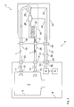
- FIG. 2 shows a functional diagram of the advantageous arrangement 1, 2 of FIG. 1 ,
- the drying device 18 of the drying module 2 comprises a fan 25, a heater 26 and a sorption column 27 through which the air can flow.
- the inlet side of the fan 25 is connected to the air inlet 16 of the drying module 2 in such a way that moist air L is present when the fan 25 is switched on flows from the washing chamber 7 of the dishwasher 1 to the fan 25.
- This air L then passes from the outlet side of the blower 25 via the heater 26 to the sorption column 27. From there, the pumped from the fan Air L via the air outlet 17 of the drying module 2 back into the washing chamber. 7
- the drying module 2 and the dishwasher 1 are connected via the control cable 21 already mentioned.
- the control cable 21 is connected to a preferably detachable connection 28 of the drying module 2 and to a likewise preferably detachable connection 29 of the dishwasher 1.
- the control cable 21 includes in the embodiment of FIG. 2 a first control line 30 and a second control line 31.
- the first control line 30 is connected to the control device 8 of the dishwasher 1 via a connection line 32 connected to the connection 29 and to the blower 25 via a connection line 33 connected to the connection 28.
- a continuous control connection 32, 30, 33 which makes it possible to control the fan 25 directly, so without the interposition of other control devices by the control device 8 of the dishwasher 1.
- the second control line 31 is connected to the control device 8 of the dishwasher 1 via a connection line 34 connected to the connection 29 and to the heating device 26 via a connecting line 35 connected to the connection 28.
- a second continuous control connection 34, 31, 35 is created, which makes it possible to control the heating device 26 directly, ie without the interposition of further control devices, by the control device 8 of the dishwasher 1.
- control connections for other types of actuators of the drying module 2 for example, a cooling unit of a condensation dryer could be provided.
- the function of the arrangement 1, 2 is now the following: During the drying cycle of a washing cycle of the dishwasher 1, the fan 25 is switched on at least temporarily by the control device 8 of the dishwasher 1, so that moist air L is led out of the rinsing chamber 7 through the sorption column 27 or along the sorption column 27. In this way, at least part of the moisture entrained in the flowing air L is deposited on or in the sorption column 27 and the air L dried thereby. The dried air L is heated by sorption heat and passed back into the washing chamber 7. The thus dried and heated air L has a high absorption capacity for water, so that the tendency to evaporation of adhering to the ware water is greatly increased.
- the drying performance of the dishwasher 1 can be substantially increased, whereby the drying cycle can be significantly shortened.
- only a small amount of energy is required, namely that which is necessary for the operation of the blower 25.
- the heater 26 may remain switched off during the drying cycle usually.
- the absorption capacity of the sorption column 27 is designed so that it is sufficient for carrying out a complete drying cycle.
- the waste heat of the regeneration can be used to heat the rinsing liquid, which lowers the energy consumption of the arrangement 1, 2.
- the fan 25 is turned on by the control device 8, so that air L is circulated from the rinsing chamber 7 as already described.
- the heater 26 is additionally switched on by the control device 8, so that the air L is heated strongly before it is fed to the sorption column 27.
- the sorption column 27 is supplied heat energy, which causes a detachment of the deposited water.
- the detached water is passed as water vapor in the slightly cooled, but still quite hot air L in the washing chamber 7. There the air gives L Heat energy to the flushing liquid located there, so that it heats up.
- the energy consumption of the arrangement 1, 2 according to the invention is nevertheless lower overall than that of a conventional dishwasher with self-drying.
- the dishwasher 1 can be designed such that the control device 8 has a first operating mode for operation without a connected drying module 2 and a second operating mode for operation with a connected drying module 2.
- the first operating mode for example, the generation of control commands for the drying module 2 can be omitted.
- control parameters for controlling a rinse cycle can be modified in order to be able to achieve an intended drying result even without a drying module 2.
- means not shown in the dishwasher 1 may be provided to prevent leakage of rinsing liquid and / or air L through the air outlet 10 or the air inlet 13 of the rinsing chamber 7 when the drying module 2 is not connected. If these agents are brought into effect, then the dishwasher 1 can be operated without any problems even without the drying module 2.
- FIG. 3 shows a functional diagram for a further advantageous embodiment of an inventive arrangement 1, 2, wherein in the following only the differences from the previous embodiment will be explained.
- the arrangement 1, 2 of FIG. 3 a modified tax concept.
- the drying module 2 comprises the FIG. 3 a separate control device 36, which is designed for teilautarken implementation of control and / or communication tasks.
- the control cable 21 includes in the embodiment of FIG. 3 only a control line 37.
- the control line 37 is connected via a connected to the connection 29 connecting line 38 to the control device 8 of the dishwasher 1 and connected via a connected to the terminal 28 connecting line 39 to the control device 36 of the drying module 2.
- a continuous control connection 38, 37, 39 which allows communication between the control device 8 of the dishwasher 1 and the control device 36 of the drying module 2.
- the control connection 38, 37, 39 may be, for example, a logical component of a data bus of the dishwasher 1.
- the control device 36 is in the example of FIG. 3 connected via a connecting line 40 to the heater 26 and via a connecting line 41 to the blower 25. In this way, the control device 8 of the dishwasher 1 can control actuators 25, 26 of the drying module 2 indirectly. Of course, other or different actuators of the drying module 2 could be controlled in this way.
Landscapes
- Washing And Drying Of Tableware (AREA)
- Drying Of Solid Materials (AREA)
Applications Claiming Priority (1)
| Application Number | Priority Date | Filing Date | Title |
|---|---|---|---|
| DE102010001343A DE102010001343A1 (de) | 2010-01-28 | 2010-01-28 | Trocknungsmodul für eine Geschirrspülmaschine |
Publications (3)
| Publication Number | Publication Date |
|---|---|
| EP2353486A2 true EP2353486A2 (fr) | 2011-08-10 |
| EP2353486A3 EP2353486A3 (fr) | 2015-01-07 |
| EP2353486B1 EP2353486B1 (fr) | 2016-06-01 |
Family
ID=43881206
Family Applications (1)
| Application Number | Title | Priority Date | Filing Date |
|---|---|---|---|
| EP11151125.9A Active EP2353486B1 (fr) | 2010-01-28 | 2011-01-17 | Module de séchage pour un lave-vaisselle |
Country Status (2)
| Country | Link |
|---|---|
| EP (1) | EP2353486B1 (fr) |
| DE (1) | DE102010001343A1 (fr) |
Cited By (6)
| Publication number | Priority date | Publication date | Assignee | Title |
|---|---|---|---|---|
| WO2013097975A1 (fr) * | 2011-12-29 | 2013-07-04 | Arcelik Anonim Sirketi | Machine à laver comprenant une unité de déshumidification |
| EP2682042A1 (fr) * | 2012-07-06 | 2014-01-08 | Indesit Company S.p.A. | Appareil ménager avec dispositif de séchage régénérable |
| US20140223761A1 (en) * | 2013-02-12 | 2014-08-14 | Lg Electronics Inc. | Dishwasher and method of controlling the same |
| KR20140101631A (ko) * | 2013-02-12 | 2014-08-20 | 엘지전자 주식회사 | 식기세척기 및 그 제어방법 |
| CN108567394A (zh) * | 2018-06-21 | 2018-09-25 | 佛山市顺德区美的洗涤电器制造有限公司 | 用于洗碗机的排风组件和洗碗机 |
| EP2842475B1 (fr) * | 2013-09-02 | 2022-02-16 | Samsung Electronics Co., Ltd. | Lave-vaisselle |
Families Citing this family (1)
| Publication number | Priority date | Publication date | Assignee | Title |
|---|---|---|---|---|
| DE102015207169B4 (de) * | 2015-04-21 | 2020-08-20 | Meiko Maschinenbau Gmbh & Co. Kg | Trocknungseinrichtung für Geschirrspülmaschinen |
Family Cites Families (10)
| Publication number | Priority date | Publication date | Assignee | Title |
|---|---|---|---|---|
| DE2322788A1 (de) | 1973-05-05 | 1974-11-28 | Ptm Pantromat Gmbh Elektrogera | Heissluftheizvorrichtung, insbesondere trocknungsvorrichtung fuer waschmaschinen oder dergl |
| JPH0411868Y2 (fr) | 1986-12-26 | 1992-03-24 | ||
| DE3830664A1 (de) | 1988-09-09 | 1990-03-22 | Bauknecht Hausgeraete | Einrichtung zum trocknen von geschirr in einer haushalt-geschirrspuelmaschine |
| US5524358A (en) | 1995-03-24 | 1996-06-11 | Matz; Warren W. | Dishwasher ventilation filtration kit |
| US20020149201A1 (en) * | 2000-06-23 | 2002-10-17 | Pichotta Michael R. | Apparatus for coupling dryer to vent ducting and method of use |
| FR2879431B1 (fr) * | 2004-12-21 | 2008-12-05 | Brandt Ind Sas | Lave-vaisselle et procede de mise en oeuvre du sechage de la vaisselle dans ce lave-vaisselle |
| ATE453356T1 (de) | 2006-05-31 | 2010-01-15 | Arcelik As | Geschirrspülmaschine mit verbesserter trockenanordnung |
| US7909939B2 (en) * | 2007-04-25 | 2011-03-22 | Illinois Tool Works, Inc. | Humidity reducing exhaust duct for dishwasher |
| DE202008017432U1 (de) * | 2008-07-23 | 2009-12-03 | BSH Bosch und Siemens Hausgeräte GmbH | Wasserführendes Haushaltsgerät, insbesondere eine Geschirrspülmaschine |
| EP2658429B1 (fr) | 2010-12-27 | 2016-08-10 | Arçelik Anonim Sirketi | Lave-vaisselle comprenant un module thermoélectrique |
-
2010
- 2010-01-28 DE DE102010001343A patent/DE102010001343A1/de not_active Withdrawn
-
2011
- 2011-01-17 EP EP11151125.9A patent/EP2353486B1/fr active Active
Non-Patent Citations (1)
| Title |
|---|
| None |
Cited By (7)
| Publication number | Priority date | Publication date | Assignee | Title |
|---|---|---|---|---|
| WO2013097975A1 (fr) * | 2011-12-29 | 2013-07-04 | Arcelik Anonim Sirketi | Machine à laver comprenant une unité de déshumidification |
| EP2682042A1 (fr) * | 2012-07-06 | 2014-01-08 | Indesit Company S.p.A. | Appareil ménager avec dispositif de séchage régénérable |
| US20140223761A1 (en) * | 2013-02-12 | 2014-08-14 | Lg Electronics Inc. | Dishwasher and method of controlling the same |
| KR20140101631A (ko) * | 2013-02-12 | 2014-08-20 | 엘지전자 주식회사 | 식기세척기 및 그 제어방법 |
| US9635997B2 (en) * | 2013-02-12 | 2017-05-02 | Lg Electronics Inc. | Dishwasher and method of controlling the same |
| EP2842475B1 (fr) * | 2013-09-02 | 2022-02-16 | Samsung Electronics Co., Ltd. | Lave-vaisselle |
| CN108567394A (zh) * | 2018-06-21 | 2018-09-25 | 佛山市顺德区美的洗涤电器制造有限公司 | 用于洗碗机的排风组件和洗碗机 |
Also Published As
| Publication number | Publication date |
|---|---|
| EP2353486B1 (fr) | 2016-06-01 |
| EP2353486A3 (fr) | 2015-01-07 |
| DE102010001343A1 (de) | 2011-08-18 |
Similar Documents
| Publication | Publication Date | Title |
|---|---|---|
| EP2353486B1 (fr) | Module de séchage pour un lave-vaisselle | |
| DE102015203132B4 (de) | Spülmaschine in Gestalt einer als Programmautomat ausgebildeten gewerblichen Utensilien- oder Geschirrspülmaschine | |
| DE102012025591B4 (de) | Verfahren zum Betreiben eines Geschirrspülers mit geschlossenem Kondenserkreis | |
| EP2473086B1 (fr) | Lave-vaisselle et procédé pour faire fonctionner un lave-vaisselle | |
| EP2292133B1 (fr) | Lave-vaisselle et procédé d'exécution d'un processus de rinçage avec un lave-vaisselle | |
| EP2301409B1 (fr) | Lave vaisselle avec élément de sorption et l'introduction de l'air | |
| EP2473085B1 (fr) | Lave-vaisselle doté d'un réservoir et procédé de préchauffage associé | |
| DE102010061215A1 (de) | Geschirrspüler mit einheitlichem Spülmodul | |
| EP2323533B1 (fr) | Procédé de lavage pour un appareil ménager à circulation d'eau, en particulier pour un lave-vaisselle | |
| DE102013204003A1 (de) | Geschirrspülmaschine mit einer Sorptionstrockenvorrichtung und einer Öffnungseinrichtung für ihre Tür | |
| EP2228001B1 (fr) | Lave-vaisselle | |
| DE102004060947A1 (de) | Haushalts-Geschirrspülmaschine und Verfahren zum Betreiben derselben | |
| DE102012207565A1 (de) | Verfahren zum Betreiben einer als Programmautomat ausgebildeten Spülmaschine sowie entsprechende Spülmaschine | |
| DE102012212636B4 (de) | Gewerbliche Spülmaschine mit Trocknungssystem sowie Verfahren zum Betreiben einer solchen Spülmaschine | |
| DE102011087322A1 (de) | Programmautomat mit Trocknungssystem sowie Verfahren zum Betreiben eines solchen Programmautomaten | |
| DE102009003012A1 (de) | Geschirrspülmaschine mit mehreren Modulen | |
| EP2326230B1 (fr) | Procédé de rinçage pour un appareil ménager avec circuit d'eau | |
| DE102013213359B3 (de) | Verfahren zum Betreiben einer Spülmaschine sowie Spülmaschine | |
| EP2289388B1 (fr) | Lave-vaisselle doté d'un réservoir à eau pour le séchage par condensation et procédé de remplissage correspondant | |
| EP2420174B1 (fr) | Lave-vaisselle doté d'une séquence de vidange améliorée | |
| EP3319501A1 (fr) | Lave-vaisselle pourvu d'un système de séchage | |
| EP2229866A2 (fr) | Lave-vaisselle doté d'un accumulateur d'eau froide | |
| EP2618712B1 (fr) | Lave-vaisselle, en particulier lave-vaisselle ménager | |
| DE102008043933A1 (de) | Haushalts-Geschirrspülmaschine mit einer Sorptionstrocknungseinrichtung sowie zugehöriges Verfahren | |
| DE102013210468B3 (de) | Verfahren zum Betreiben einer Spülmaschine sowie Spülmaschine |
Legal Events
| Date | Code | Title | Description |
|---|---|---|---|
| PUAI | Public reference made under article 153(3) epc to a published international application that has entered the european phase |
Free format text: ORIGINAL CODE: 0009012 |
|
| AK | Designated contracting states |
Kind code of ref document: A2 Designated state(s): AL AT BE BG CH CY CZ DE DK EE ES FI FR GB GR HR HU IE IS IT LI LT LU LV MC MK MT NL NO PL PT RO RS SE SI SK SM TR |
|
| AX | Request for extension of the european patent |
Extension state: BA ME |
|
| PUAL | Search report despatched |
Free format text: ORIGINAL CODE: 0009013 |
|
| AK | Designated contracting states |
Kind code of ref document: A3 Designated state(s): AL AT BE BG CH CY CZ DE DK EE ES FI FR GB GR HR HU IE IS IT LI LT LU LV MC MK MT NL NO PL PT RO RS SE SI SK SM TR |
|
| AX | Request for extension of the european patent |
Extension state: BA ME |
|
| RIC1 | Information provided on ipc code assigned before grant |
Ipc: A47L 15/48 20060101AFI20141203BHEP |
|
| RAP1 | Party data changed (applicant data changed or rights of an application transferred) |
Owner name: BSH HAUSGERAETE GMBH |
|
| 17P | Request for examination filed |
Effective date: 20150707 |
|
| RBV | Designated contracting states (corrected) |
Designated state(s): AL AT BE BG CH CY CZ DE DK EE ES FI FR GB GR HR HU IE IS IT LI LT LU LV MC MK MT NL NO PL PT RO RS SE SI SK SM TR |
|
| GRAP | Despatch of communication of intention to grant a patent |
Free format text: ORIGINAL CODE: EPIDOSNIGR1 |
|
| INTG | Intention to grant announced |
Effective date: 20160108 |
|
| RIN1 | Information on inventor provided before grant (corrected) |
Inventor name: ROSENBAUER, MICHAEL GEORG Inventor name: JERG, HELMUT |
|
| GRAS | Grant fee paid |
Free format text: ORIGINAL CODE: EPIDOSNIGR3 |
|
| GRAA | (expected) grant |
Free format text: ORIGINAL CODE: 0009210 |
|
| AK | Designated contracting states |
Kind code of ref document: B1 Designated state(s): AL AT BE BG CH CY CZ DE DK EE ES FI FR GB GR HR HU IE IS IT LI LT LU LV MC MK MT NL NO PL PT RO RS SE SI SK SM TR |
|
| REG | Reference to a national code |
Ref country code: GB Ref legal event code: FG4D Free format text: NOT ENGLISH |
|
| REG | Reference to a national code |
Ref country code: CH Ref legal event code: EP Ref country code: AT Ref legal event code: REF Ref document number: 803332 Country of ref document: AT Kind code of ref document: T Effective date: 20160615 |
|
| REG | Reference to a national code |
Ref country code: IE Ref legal event code: FG4D Free format text: LANGUAGE OF EP DOCUMENT: GERMAN |
|
| REG | Reference to a national code |
Ref country code: DE Ref legal event code: R096 Ref document number: 502011009858 Country of ref document: DE |
|
| REG | Reference to a national code |
Ref country code: LT Ref legal event code: MG4D |
|
| REG | Reference to a national code |
Ref country code: NL Ref legal event code: MP Effective date: 20160601 |
|
| PG25 | Lapsed in a contracting state [announced via postgrant information from national office to epo] |
Ref country code: LT Free format text: LAPSE BECAUSE OF FAILURE TO SUBMIT A TRANSLATION OF THE DESCRIPTION OR TO PAY THE FEE WITHIN THE PRESCRIBED TIME-LIMIT Effective date: 20160601 Ref country code: FI Free format text: LAPSE BECAUSE OF FAILURE TO SUBMIT A TRANSLATION OF THE DESCRIPTION OR TO PAY THE FEE WITHIN THE PRESCRIBED TIME-LIMIT Effective date: 20160601 Ref country code: NO Free format text: LAPSE BECAUSE OF FAILURE TO SUBMIT A TRANSLATION OF THE DESCRIPTION OR TO PAY THE FEE WITHIN THE PRESCRIBED TIME-LIMIT Effective date: 20160901 |
|
| PG25 | Lapsed in a contracting state [announced via postgrant information from national office to epo] |
Ref country code: ES Free format text: LAPSE BECAUSE OF FAILURE TO SUBMIT A TRANSLATION OF THE DESCRIPTION OR TO PAY THE FEE WITHIN THE PRESCRIBED TIME-LIMIT Effective date: 20160601 Ref country code: GR Free format text: LAPSE BECAUSE OF FAILURE TO SUBMIT A TRANSLATION OF THE DESCRIPTION OR TO PAY THE FEE WITHIN THE PRESCRIBED TIME-LIMIT Effective date: 20160902 Ref country code: RS Free format text: LAPSE BECAUSE OF FAILURE TO SUBMIT A TRANSLATION OF THE DESCRIPTION OR TO PAY THE FEE WITHIN THE PRESCRIBED TIME-LIMIT Effective date: 20160601 Ref country code: NL Free format text: LAPSE BECAUSE OF FAILURE TO SUBMIT A TRANSLATION OF THE DESCRIPTION OR TO PAY THE FEE WITHIN THE PRESCRIBED TIME-LIMIT Effective date: 20160601 Ref country code: SE Free format text: LAPSE BECAUSE OF FAILURE TO SUBMIT A TRANSLATION OF THE DESCRIPTION OR TO PAY THE FEE WITHIN THE PRESCRIBED TIME-LIMIT Effective date: 20160601 Ref country code: LV Free format text: LAPSE BECAUSE OF FAILURE TO SUBMIT A TRANSLATION OF THE DESCRIPTION OR TO PAY THE FEE WITHIN THE PRESCRIBED TIME-LIMIT Effective date: 20160601 |
|
| REG | Reference to a national code |
Ref country code: DE Ref legal event code: R026 Ref document number: 502011009858 Country of ref document: DE |
|
| PLBI | Opposition filed |
Free format text: ORIGINAL CODE: 0009260 |
|
| PG25 | Lapsed in a contracting state [announced via postgrant information from national office to epo] |
Ref country code: SK Free format text: LAPSE BECAUSE OF FAILURE TO SUBMIT A TRANSLATION OF THE DESCRIPTION OR TO PAY THE FEE WITHIN THE PRESCRIBED TIME-LIMIT Effective date: 20160601 Ref country code: EE Free format text: LAPSE BECAUSE OF FAILURE TO SUBMIT A TRANSLATION OF THE DESCRIPTION OR TO PAY THE FEE WITHIN THE PRESCRIBED TIME-LIMIT Effective date: 20160601 Ref country code: IT Free format text: LAPSE BECAUSE OF FAILURE TO SUBMIT A TRANSLATION OF THE DESCRIPTION OR TO PAY THE FEE WITHIN THE PRESCRIBED TIME-LIMIT Effective date: 20160601 Ref country code: IS Free format text: LAPSE BECAUSE OF FAILURE TO SUBMIT A TRANSLATION OF THE DESCRIPTION OR TO PAY THE FEE WITHIN THE PRESCRIBED TIME-LIMIT Effective date: 20161001 Ref country code: CZ Free format text: LAPSE BECAUSE OF FAILURE TO SUBMIT A TRANSLATION OF THE DESCRIPTION OR TO PAY THE FEE WITHIN THE PRESCRIBED TIME-LIMIT Effective date: 20160601 Ref country code: RO Free format text: LAPSE BECAUSE OF FAILURE TO SUBMIT A TRANSLATION OF THE DESCRIPTION OR TO PAY THE FEE WITHIN THE PRESCRIBED TIME-LIMIT Effective date: 20160601 |
|
| PG25 | Lapsed in a contracting state [announced via postgrant information from national office to epo] |
Ref country code: PT Free format text: LAPSE BECAUSE OF FAILURE TO SUBMIT A TRANSLATION OF THE DESCRIPTION OR TO PAY THE FEE WITHIN THE PRESCRIBED TIME-LIMIT Effective date: 20161003 Ref country code: SM Free format text: LAPSE BECAUSE OF FAILURE TO SUBMIT A TRANSLATION OF THE DESCRIPTION OR TO PAY THE FEE WITHIN THE PRESCRIBED TIME-LIMIT Effective date: 20160601 Ref country code: PL Free format text: LAPSE BECAUSE OF FAILURE TO SUBMIT A TRANSLATION OF THE DESCRIPTION OR TO PAY THE FEE WITHIN THE PRESCRIBED TIME-LIMIT Effective date: 20160601 |
|
| 26 | Opposition filed |
Opponent name: SANHUA AWECO APPLIANCE SYSTEMS GMBH Effective date: 20170126 |
|
| PLAX | Notice of opposition and request to file observation + time limit sent |
Free format text: ORIGINAL CODE: EPIDOSNOBS2 |
|
| PG25 | Lapsed in a contracting state [announced via postgrant information from national office to epo] |
Ref country code: SI Free format text: LAPSE BECAUSE OF FAILURE TO SUBMIT A TRANSLATION OF THE DESCRIPTION OR TO PAY THE FEE WITHIN THE PRESCRIBED TIME-LIMIT Effective date: 20160601 Ref country code: BE Free format text: LAPSE BECAUSE OF NON-PAYMENT OF DUE FEES Effective date: 20170131 Ref country code: DK Free format text: LAPSE BECAUSE OF FAILURE TO SUBMIT A TRANSLATION OF THE DESCRIPTION OR TO PAY THE FEE WITHIN THE PRESCRIBED TIME-LIMIT Effective date: 20160601 |
|
| PLBB | Reply of patent proprietor to notice(s) of opposition received |
Free format text: ORIGINAL CODE: EPIDOSNOBS3 |
|
| REG | Reference to a national code |
Ref country code: CH Ref legal event code: PL |
|
| GBPC | Gb: european patent ceased through non-payment of renewal fee |
Effective date: 20170117 |
|
| PG25 | Lapsed in a contracting state [announced via postgrant information from national office to epo] |
Ref country code: MC Free format text: LAPSE BECAUSE OF FAILURE TO SUBMIT A TRANSLATION OF THE DESCRIPTION OR TO PAY THE FEE WITHIN THE PRESCRIBED TIME-LIMIT Effective date: 20160601 |
|
| REG | Reference to a national code |
Ref country code: FR Ref legal event code: ST Effective date: 20170929 |
|
| PG25 | Lapsed in a contracting state [announced via postgrant information from national office to epo] |
Ref country code: CH Free format text: LAPSE BECAUSE OF NON-PAYMENT OF DUE FEES Effective date: 20170131 Ref country code: FR Free format text: LAPSE BECAUSE OF NON-PAYMENT OF DUE FEES Effective date: 20170131 Ref country code: LI Free format text: LAPSE BECAUSE OF NON-PAYMENT OF DUE FEES Effective date: 20170131 |
|
| REG | Reference to a national code |
Ref country code: IE Ref legal event code: MM4A |
|
| PG25 | Lapsed in a contracting state [announced via postgrant information from national office to epo] |
Ref country code: LU Free format text: LAPSE BECAUSE OF NON-PAYMENT OF DUE FEES Effective date: 20170117 Ref country code: GB Free format text: LAPSE BECAUSE OF NON-PAYMENT OF DUE FEES Effective date: 20170117 |
|
| REG | Reference to a national code |
Ref country code: BE Ref legal event code: MM Effective date: 20170131 |
|
| PG25 | Lapsed in a contracting state [announced via postgrant information from national office to epo] |
Ref country code: IE Free format text: LAPSE BECAUSE OF NON-PAYMENT OF DUE FEES Effective date: 20170117 |
|
| REG | Reference to a national code |
Ref country code: AT Ref legal event code: MM01 Ref document number: 803332 Country of ref document: AT Kind code of ref document: T Effective date: 20170117 |
|
| PG25 | Lapsed in a contracting state [announced via postgrant information from national office to epo] |
Ref country code: AT Free format text: LAPSE BECAUSE OF NON-PAYMENT OF DUE FEES Effective date: 20170117 |
|
| PG25 | Lapsed in a contracting state [announced via postgrant information from national office to epo] |
Ref country code: MT Free format text: LAPSE BECAUSE OF FAILURE TO SUBMIT A TRANSLATION OF THE DESCRIPTION OR TO PAY THE FEE WITHIN THE PRESCRIBED TIME-LIMIT Effective date: 20160601 |
|
| PG25 | Lapsed in a contracting state [announced via postgrant information from national office to epo] |
Ref country code: AL Free format text: LAPSE BECAUSE OF FAILURE TO SUBMIT A TRANSLATION OF THE DESCRIPTION OR TO PAY THE FEE WITHIN THE PRESCRIBED TIME-LIMIT Effective date: 20160601 |
|
| PLCK | Communication despatched that opposition was rejected |
Free format text: ORIGINAL CODE: EPIDOSNREJ1 |
|
| STAA | Information on the status of an ep patent application or granted ep patent |
Free format text: STATUS: THE PATENT HAS BEEN GRANTED |
|
| APBM | Appeal reference recorded |
Free format text: ORIGINAL CODE: EPIDOSNREFNO |
|
| APBP | Date of receipt of notice of appeal recorded |
Free format text: ORIGINAL CODE: EPIDOSNNOA2O |
|
| APAH | Appeal reference modified |
Free format text: ORIGINAL CODE: EPIDOSCREFNO |
|
| PG25 | Lapsed in a contracting state [announced via postgrant information from national office to epo] |
Ref country code: HU Free format text: LAPSE BECAUSE OF FAILURE TO SUBMIT A TRANSLATION OF THE DESCRIPTION OR TO PAY THE FEE WITHIN THE PRESCRIBED TIME-LIMIT; INVALID AB INITIO Effective date: 20110117 |
|
| REG | Reference to a national code |
Ref country code: DE Ref legal event code: R100 Ref document number: 502011009858 Country of ref document: DE |
|
| PLBP | Opposition withdrawn |
Free format text: ORIGINAL CODE: 0009264 |
|
| APBU | Appeal procedure closed |
Free format text: ORIGINAL CODE: EPIDOSNNOA9O |
|
| PLBN | Opposition rejected |
Free format text: ORIGINAL CODE: 0009273 |
|
| STAA | Information on the status of an ep patent application or granted ep patent |
Free format text: STATUS: OPPOSITION REJECTED |
|
| PG25 | Lapsed in a contracting state [announced via postgrant information from national office to epo] |
Ref country code: BG Free format text: LAPSE BECAUSE OF FAILURE TO SUBMIT A TRANSLATION OF THE DESCRIPTION OR TO PAY THE FEE WITHIN THE PRESCRIBED TIME-LIMIT Effective date: 20160601 |
|
| 27O | Opposition rejected |
Effective date: 20190718 |
|
| PG25 | Lapsed in a contracting state [announced via postgrant information from national office to epo] |
Ref country code: CY Free format text: LAPSE BECAUSE OF NON-PAYMENT OF DUE FEES Effective date: 20160601 |
|
| PG25 | Lapsed in a contracting state [announced via postgrant information from national office to epo] |
Ref country code: MK Free format text: LAPSE BECAUSE OF FAILURE TO SUBMIT A TRANSLATION OF THE DESCRIPTION OR TO PAY THE FEE WITHIN THE PRESCRIBED TIME-LIMIT Effective date: 20160601 |
|
| PG25 | Lapsed in a contracting state [announced via postgrant information from national office to epo] |
Ref country code: TR Free format text: LAPSE BECAUSE OF FAILURE TO SUBMIT A TRANSLATION OF THE DESCRIPTION OR TO PAY THE FEE WITHIN THE PRESCRIBED TIME-LIMIT Effective date: 20160601 |
|
| PG25 | Lapsed in a contracting state [announced via postgrant information from national office to epo] |
Ref country code: HR Free format text: LAPSE BECAUSE OF FAILURE TO SUBMIT A TRANSLATION OF THE DESCRIPTION OR TO PAY THE FEE WITHIN THE PRESCRIBED TIME-LIMIT Effective date: 20160601 |
|
| PGFP | Annual fee paid to national office [announced via postgrant information from national office to epo] |
Ref country code: DE Payment date: 20240131 Year of fee payment: 14 |