EP2353486A2 - Dryer module for a dishwasher - Google Patents
Dryer module for a dishwasher Download PDFInfo
- Publication number
- EP2353486A2 EP2353486A2 EP11151125A EP11151125A EP2353486A2 EP 2353486 A2 EP2353486 A2 EP 2353486A2 EP 11151125 A EP11151125 A EP 11151125A EP 11151125 A EP11151125 A EP 11151125A EP 2353486 A2 EP2353486 A2 EP 2353486A2
- Authority
- EP
- European Patent Office
- Prior art keywords
- dishwasher
- drying
- drying module
- air
- control device
- Prior art date
- Legal status (The legal status is an assumption and is not a legal conclusion. Google has not performed a legal analysis and makes no representation as to the accuracy of the status listed.)
- Granted
Links
Images


Classifications
-
- A—HUMAN NECESSITIES
- A47—FURNITURE; DOMESTIC ARTICLES OR APPLIANCES; COFFEE MILLS; SPICE MILLS; SUCTION CLEANERS IN GENERAL
- A47L—DOMESTIC WASHING OR CLEANING; SUCTION CLEANERS IN GENERAL
- A47L15/00—Washing or rinsing machines for crockery or tableware
- A47L15/42—Details
- A47L15/48—Drying arrangements
- A47L15/481—Drying arrangements by using water absorbent materials, e.g. Zeolith
Definitions
- the present invention relates to a drying module for drying air from a washing chamber of a dishwasher, in particular a household dishwasher.
- a typical rinse includes one or more water-bearing partial rinses or cleaning cycles and a drying cycle.
- the drying of the dishes is based on the principle of so-called self-drying.
- the items to be washed are heated to a high temperature during the last cleaning cycle.
- water droplets adhering to the hot item to be washed evaporate in the subsequent drying cycle and precipitate on the inside of the rinse container due to the lower temperature prevailing there.
- an intended drying result can be achieved in a reasonable time only under too high an energy input for heating the dishes.
- a disadvantage of the known dishwasher is thus their unsatisfactory drying efficiency.
- the object of the present invention is to improve the drying efficiency of a dishwasher.
- a drying module of the type mentioned above which is designed as outside the dishwasher, in particular separately, arrangeable unit, and which an air inlet, which is connectable to receive the air to be dried with the dishwasher, a drying device for drying the recorded Air and an air outlet, which is connectable to the dispensing of the dried air with the dishwasher comprises.
- the drying module according to the invention makes it possible to remove moist air from the rinsing chamber, to dry the extracted air and to return the dried air to the rinsing chamber.
- the moisture content of the air in the rinsing chamber can be significantly reduced.
- This in turn increases the tendency to evaporate adhering to the ware water droplets, so that the drying performance of the dishwasher increases.
- This allows a reduction in the duration of time and / or a reduction in the use of energy when heating the items to be washed in the last cleaning cycle. Consequently, by using the drying module according to the invention, the drying efficiency of the dishwasher can be improved.
- the drying module according to the invention also avoids a burden on the environment of the dishwasher with unwanted moisture, since the moist air from the washing chamber can not be discharged to the outside, but can be performed in the closed circuit and dried.
- the drying module according to the invention is designed as outside of the outer walls of the dishwasher, especially outside of a possibly existing housing of the dishwasher, preferably separately, can be used in known dishwashers, without these would have to be significantly adapted in terms of design. In particular, it is not necessary to change the design of the known dishwashers so that a free space for receiving the drying module is formed.
- the drying module according to the invention can also be used in particular in dishwashers with compact housing dimensions, which would not allow the installation of a drying module.
- the drying module according to the invention can be used without problems in a tabletop dishwasher or a dishwasher with a width of only 45 cm.
- the drying module according to the invention is also superior to such proposals for improving the drying efficiency of a dishwasher, which provide means for cooling a condensation surface of the washing chamber, as these can not be used in many cases, for reasons of space, especially in compact dishwashers.
- the drying module according to the invention can be arranged, for example, between the back of the dishwasher and a building-side wall. If the dishwasher is integrated in a kitchenette, the drying module can in particular be accommodated in a base area of the kitchen unit below the dishwasher or in a cabinet adjacent to the dishwasher.
- the drying device has a fan.
- the blower can be designed, for example, as an axial fan, as a radial fan or as a tangential fan.
- the drying device is designed as a sorption drying device.
- a sorption drying device has a sorption column through which the air to be dried flows or can be flowed around, with a water-sorbing material.
- the water-sorbing material also called hygroscopic material, can be a liquid, for example an aqueous salt solution of lithium chloride, lithium bromide, calcium chloride or the like, or a solid, for example a silicate, in particular zeolite.
- the air taken up by the drying module is now conducted through the hygroscopic material or along the hygroscopic material, at least part of the water vapor entrained in the air is deposited in or on the hygroscopic material, so that moisture is removed from the air.
- sorption heat is released, which by the drying module heated air, so that their relative humidity continues to fall. Due to the now very dry air returned to the rinsing chamber results in an excellent drying performance, which benefits a low drying time. The drying of the air itself by means of sorption requires no energy.
- the drying device could also be designed as a condensation drying device, in which the air to be dried is conducted past a cooled condensation surface in order to condense there.
- this often results in a higher energy consumption.
- the sorption drying device comprises a heating device for heating the sorption column.
- a heating device integrated in the sorption drying device allows a simple regeneration of the sorption column by supplying heat energy.
- the drying module has at least one connection for connecting a control line connected to a control device of the dishwasher.
- a control device for controlling rinses for cleaning items to be washed.
- Such control devices can be designed, in particular, as a sequence control device which is designed to control a sequence of a rinse cycle on the basis of a selectable rinse program.
- the control line between the control device of the dishwasher and the drying module it is possible to adapt the function of the drying module to the course of a wash cycle of the dishwasher.
- the execution of the drying function for the air of the rinsing chamber and the execution of the regeneration function for a sorption column takes place in adaptation to a time course of a rinse cycle.
- the execution of the drying function usually makes sense only during the drying cycle to dry the dishes.
- carrying out the regeneration function is particularly useful during a cleaning cycle which provides heating of a rinsing liquid. In this way, the waste heat released during the regeneration can be used to heat the rinsing liquid, which lowers the energy requirement of a heating of the dishwasher.
- connection is connected to an actuator of the drying module.
- Actuators here are understood to be controllable technical elements of the drying module, in particular blowers and heating devices.
- the control device of the dishwasher can intervene in a simple manner directly in the function of the drying module. This facilitates the synchronization of the processes of the drying module and the dishwasher. In many cases, it can also be dispensed with to provide the drying module with its own control device.
- connection is connected to a control device of the drying module.
- a control device of the drying module As a result, an interaction of a control device of the drying module with the control device of the dishwasher is possible.
- the equipment of the drying module with its own control device makes it possible for the drying module to perform at least some functions autonomously.
- the wiring effort between the drying module and the dishwasher can be reduced, even if the drying module has a plurality of actuators to be controlled.
- the drying module is prepared for mounting on a wall.
- the drying module can have fastening sections which can be designed, for example, as fastening straps.
- the attachment portions may include attachment holes and / or slots for securing the drying module to a wall with screws, hooks or the like. This makes it possible in a simple manner, the drying module to save space on a building wall or on a wall unit.
- the drying module is prepared for placement on a horizontal surface.
- adjusting sections for example adjustable feet, can be provided. This makes it possible to place the drying module without further attachment to a floor, such as a building floor or cabinet floor.
- the drying module is in a cuboid installation space with a depth of 50 cm, preferably with a depth of 45 cm, particularly preferably with a depth of 40 cm, with a width of 56 cm, preferably with a width of 41 cm, particularly preferably with a width of 26 cm, and with a height of 16 cm, preferably with a height of 11 cm, can be arranged.
- a trained drying module can be arranged to save space and is therefore particularly suitable for smaller kitchens. It is possible to arrange the drying module in the base area of common kitchen furniture, which in many cases have rooms with such dimensions, which have not been used in most cases.
- the drying module can be dimensioned such that it has a width of about 200 mm, a height of about 90 mm and a depth of about 400 mm.
- the drying module has a substantially closed housing.
- the housing can in particular serve to protect the drying device against dirt and / or damage.
- Such a housing allows the placement of the drying module independently from the presence of protective cabinets and the like. This expands the possible uses of the drying module.
- fastening sections for wall mounting and / or adjusting sections for setting up the drying module on a base can be formed on the housing in a simple manner.
- the invention relates to a dishwasher, in particular a domestic dishwasher, with a rinsing chamber for receiving items to be washed during a rinse cycle.
- the rinsing chamber has an air outlet, which is provided for connection to the air inlet of the drying module, and an air inlet, which is provided for connection to the air outlet of the drying module.
- means for closing the air outlet and / or means for closing the air inlet are provided.
- the dishwashing machine according to the invention can also be operated without a drying module, since in this way unwanted discharge of water vapor or rinsing liquid from the rinsing chamber can be prevented when the drying module is not connected.
- the closure means may be, for example, flaps, slides or plugs.
- the dishwasher has a control device for controlling rinses for cleaning the items to be washed, which is additionally designed to control the drying module.
- control device is designed to control at least one actuator of the drying module.
- control device of the dishwasher can intervene in a simple manner directly in the function of the drying module. This facilitates the synchronization of the processes of the drying module and the dishwasher. In particular, so drying modules can be controlled, which do not have their own control device.
- control device of the dishwasher is designed for communication with a control device of the drying module.
- the cabling effort can be reduced, in particular if the drying module has a plurality of actuators.
- a distribution of control tasks is possible.
- the control device has a first operating mode and a second operating mode for carrying out rinsing operations, wherein the first operating mode is provided for operation without a connected drying module and the second operating mode is provided for operation with a connected drying module.
- at least one control parameter for carrying out a wash cycle may differ in order to adapt the course of the wash cycle to the respective conditions. So can For example, in the first operating mode, a control parameter for specifying the duration of a drying cycle having a higher value than in the second mode, so as to be able to achieve a satisfactory drying result even at lower drying performance.
- a control parameter for specifying the temperature of the last cleaning cycle of a rinse cycle may have a higher value than in the second mode of operation in order to heat up the ware more effectively in order to achieve the desired drying result despite the absence of a drying module.
- the generation of control commands for the drying module can be omitted.
- the present invention relates to an arrangement with a dishwasher, in particular with a domestic dishwasher and with a drying module for drying air from a washing chamber of the dishwasher.
- At least the dishwasher or at least the drying module is designed according to the invention.
- FIG. 1 shows an advantageous embodiment of an inventive arrangement 1, 2, which comprises a dishwasher 1 and a drying module 2.
- the drying module 2 is placed in a kitchen cabinet 3 adjacent to the dishwasher 1 and shown with dashed lines.
- the dishwasher 1 is designed for cleaning items to be washed using rinsing liquid, in particular for cleaning dishes, and has a housing 4 in which a rinsing container 5 is arranged.
- the washing container 5 is associated with a door 6, which makes it possible to introduce items to be washed in the washing 5 or remove it.
- a substantially closed rinsing chamber is formed inside the rinsing container 5.
- the outer housing can be partially or completely omitted. This is the case in particular with built-in dishwashers. The expenses of the dishwasher can then be formed for the most part only by the walls of the washing.
- the dishwasher 1 further comprises a control device 8 for controlling rinses for cleaning items to be washed.
- the control device 8 may in particular be designed as a sequence control device, which is designed to control a sequence of a rinse cycle on the basis of a selectable rinse program.
- the control device 8 is connected to an operator interface 9, which is provided for operating the dishwasher 1 by an operator.
- the user interface 9 can be next to one for operating the dishwasher 1 input unit also include an output unit for outputting information to the operator.
- the rinsing chamber 7 of the dishwasher 1 has an air outlet 10 which is connected to a connecting line 11, which in turn is connected to a connection piece 12 arranged on the housing 4.
- the air outlet 10, the connecting line 11 and the connecting piece 12 are designed to remove air L from the washing chamber 7 out.
- the rinsing chamber 7 of the dishwasher 1 has an air inlet 13 which is connected to a connecting line 14, which in turn is connected to a connection piece 15 arranged on the housing 4.
- the air inlet 13, the connecting line 14 and the connecting piece 15 are provided for introducing air L into the rinsing chamber 7.
- the drying module 2 comprises an air inlet 16, an air outlet 17 and a drying device 18.
- the drying device 18 is connected to the air inlet 16 and the air outlet 17 so that air L flowing into the air inlet 16 passes through the drying device 18 and from the drying device 18 is led to the air outlet 17, there to leave the drying module 2 again.
- the drying device 18 is designed to dry the air L passed through it, so that the air L leaving the air outlet 17 has a lower absolute moisture content than the air entering the air inlet 16 L.
- the air inlet 16 of the drying module 2 is intended connected to the dishwasher 1 via a connecting line 19, preferably designed as a flexible connecting hose, such that the drying module 2 can receive moist air L from the washing chamber 7 of the dishwasher 1 via the air inlet 16.
- a connecting line 19 preferably designed as a flexible connecting hose, such that the drying module 2 can receive moist air L from the washing chamber 7 of the dishwasher 1 via the air inlet 16.
- the dishwasher-side end of the connecting hose 19 outside the housing 4 of the dishwasher 1 is connected to the connecting piece 12.
- the air outlet 17 of the drying module 2 is provided as intended via a connecting line 20 preferably designed as a flexible connecting hose connected to the dishwasher 1 that the drying module 2 can deliver dried air L to the dishwasher 1.
- a connecting line 20 preferably designed as a flexible connecting hose connected to the dishwasher 1 that the drying module 2 can deliver dried air L to the dishwasher 1.
- the dishwasher-side end of the connecting tube 20 outside the outer walls, here the housing 4 of the dishwasher 1 is connected to the connecting piece 15.
- connections of the connecting hose 19 with the connecting piece 12 and the air inlet 16 may, like the connections of the connecting hose 20 to the connecting piece 15 and the air outlet 17, be designed as detachable screwed, plugged or latched connections.
- control cable 21 which comprises one or more control lines, which make it possible to adapt the function of the drying module 2 to the course of a wash cycle of the dishwasher 1.
- the control cable 21 may conveniently be connected via detachable plug connections or the like with the dishwasher 1 and / or the drying module 2.
- the arrangement 1, 2 according to the invention also prevents contamination of the environment with unwanted moisture, since the moist air L from the rinsing chamber 7 is not discharged to the outside, but can be performed in the closed circuit and dried.
- the drying module 2 is designed as an independent or separate assembly 2 which can be arranged outside the outer walls of the dishwasher, here in the exemplary embodiment outside the walls of the housing 4 of the dishwasher 1. It has a substantially closed housing 22, which in particular can have a supporting function and / or a protective function. Thus, it is not necessary to provide a free space for receiving the drying module 2 in the dishwasher 1. As a result, the dishwasher 1 can have compact housing dimensions.
- the drying module 2 is arranged in a base region 23 of the kitchen cabinet 3.
- a base region 23 of the kitchen cabinet 3 Such a placement of the drying module 2 is possible and useful in many kitchen cabinets 3, which have in their base region 23 below a lowermost floor 24 or below a lowermost drawer a sufficiently large cuboid installation space.
- Many standard kitchen cabinets 3 provide in their base area 23 an otherwise unused installation space with a depth of for example 50 cm, 45 cm or 40 cm, with a width of 56 cm, 41 cm or 26 cm, and with a height of 16 cm or 11 cm , Therefore, it makes sense to form the drying module 2 such that it can be arranged in installation spaces with such dimensions.
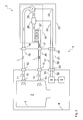
- FIG. 2 shows a functional diagram of the advantageous arrangement 1, 2 of FIG. 1 ,
- the drying device 18 of the drying module 2 comprises a fan 25, a heater 26 and a sorption column 27 through which the air can flow.
- the inlet side of the fan 25 is connected to the air inlet 16 of the drying module 2 in such a way that moist air L is present when the fan 25 is switched on flows from the washing chamber 7 of the dishwasher 1 to the fan 25.
- This air L then passes from the outlet side of the blower 25 via the heater 26 to the sorption column 27. From there, the pumped from the fan Air L via the air outlet 17 of the drying module 2 back into the washing chamber. 7
- the drying module 2 and the dishwasher 1 are connected via the control cable 21 already mentioned.
- the control cable 21 is connected to a preferably detachable connection 28 of the drying module 2 and to a likewise preferably detachable connection 29 of the dishwasher 1.
- the control cable 21 includes in the embodiment of FIG. 2 a first control line 30 and a second control line 31.
- the first control line 30 is connected to the control device 8 of the dishwasher 1 via a connection line 32 connected to the connection 29 and to the blower 25 via a connection line 33 connected to the connection 28.
- a continuous control connection 32, 30, 33 which makes it possible to control the fan 25 directly, so without the interposition of other control devices by the control device 8 of the dishwasher 1.
- the second control line 31 is connected to the control device 8 of the dishwasher 1 via a connection line 34 connected to the connection 29 and to the heating device 26 via a connecting line 35 connected to the connection 28.
- a second continuous control connection 34, 31, 35 is created, which makes it possible to control the heating device 26 directly, ie without the interposition of further control devices, by the control device 8 of the dishwasher 1.
- control connections for other types of actuators of the drying module 2 for example, a cooling unit of a condensation dryer could be provided.
- the function of the arrangement 1, 2 is now the following: During the drying cycle of a washing cycle of the dishwasher 1, the fan 25 is switched on at least temporarily by the control device 8 of the dishwasher 1, so that moist air L is led out of the rinsing chamber 7 through the sorption column 27 or along the sorption column 27. In this way, at least part of the moisture entrained in the flowing air L is deposited on or in the sorption column 27 and the air L dried thereby. The dried air L is heated by sorption heat and passed back into the washing chamber 7. The thus dried and heated air L has a high absorption capacity for water, so that the tendency to evaporation of adhering to the ware water is greatly increased.
- the drying performance of the dishwasher 1 can be substantially increased, whereby the drying cycle can be significantly shortened.
- only a small amount of energy is required, namely that which is necessary for the operation of the blower 25.
- the heater 26 may remain switched off during the drying cycle usually.
- the absorption capacity of the sorption column 27 is designed so that it is sufficient for carrying out a complete drying cycle.
- the waste heat of the regeneration can be used to heat the rinsing liquid, which lowers the energy consumption of the arrangement 1, 2.
- the fan 25 is turned on by the control device 8, so that air L is circulated from the rinsing chamber 7 as already described.
- the heater 26 is additionally switched on by the control device 8, so that the air L is heated strongly before it is fed to the sorption column 27.
- the sorption column 27 is supplied heat energy, which causes a detachment of the deposited water.
- the detached water is passed as water vapor in the slightly cooled, but still quite hot air L in the washing chamber 7. There the air gives L Heat energy to the flushing liquid located there, so that it heats up.
- the energy consumption of the arrangement 1, 2 according to the invention is nevertheless lower overall than that of a conventional dishwasher with self-drying.
- the dishwasher 1 can be designed such that the control device 8 has a first operating mode for operation without a connected drying module 2 and a second operating mode for operation with a connected drying module 2.
- the first operating mode for example, the generation of control commands for the drying module 2 can be omitted.
- control parameters for controlling a rinse cycle can be modified in order to be able to achieve an intended drying result even without a drying module 2.
- means not shown in the dishwasher 1 may be provided to prevent leakage of rinsing liquid and / or air L through the air outlet 10 or the air inlet 13 of the rinsing chamber 7 when the drying module 2 is not connected. If these agents are brought into effect, then the dishwasher 1 can be operated without any problems even without the drying module 2.
- FIG. 3 shows a functional diagram for a further advantageous embodiment of an inventive arrangement 1, 2, wherein in the following only the differences from the previous embodiment will be explained.
- the arrangement 1, 2 of FIG. 3 a modified tax concept.
- the drying module 2 comprises the FIG. 3 a separate control device 36, which is designed for teilautarken implementation of control and / or communication tasks.
- the control cable 21 includes in the embodiment of FIG. 3 only a control line 37.
- the control line 37 is connected via a connected to the connection 29 connecting line 38 to the control device 8 of the dishwasher 1 and connected via a connected to the terminal 28 connecting line 39 to the control device 36 of the drying module 2.
- a continuous control connection 38, 37, 39 which allows communication between the control device 8 of the dishwasher 1 and the control device 36 of the drying module 2.
- the control connection 38, 37, 39 may be, for example, a logical component of a data bus of the dishwasher 1.
- the control device 36 is in the example of FIG. 3 connected via a connecting line 40 to the heater 26 and via a connecting line 41 to the blower 25. In this way, the control device 8 of the dishwasher 1 can control actuators 25, 26 of the drying module 2 indirectly. Of course, other or different actuators of the drying module 2 could be controlled in this way.
Abstract
Description
Die vorliegende Erfindung betrifft ein Trocknungsmodul zur Trocknung von Luft aus einer Spülkammer einer Geschirrspülmaschine, insbesondere einer Haushaltsgeschirrspülmaschine.The present invention relates to a drying module for drying air from a washing chamber of a dishwasher, in particular a household dishwasher.
Bei modernen Geschirrspülmaschinen wird das Spülgut, insbesondere zu spülendes Geschirr, in eine Spülkammer eingebracht und dort in einem Spülprozess, der auch Spülgang genannt wird, unter Zuhilfenahme von Wasser gereinigt und anschließend getrocknet. Ein typischer Spülgang umfasst dabei einen oder mehrere wasserführende Teilspülgänge bzw. Reinigungsgänge sowie einen Trocknungsgang.In modern dishwashers, the items to be washed, in particular dishes to be washed, are introduced into a rinsing chamber and are there cleaned in a rinsing process, which is also called a rinse, with the aid of water and then dried. A typical rinse includes one or more water-bearing partial rinses or cleaning cycles and a drying cycle.
Bei einer aus der Praxis bekannten Geschirrspülmaschine beruht das Trocknen des Spülguts auf dem Prinzip der sogenannten Eigentrocknung. Dabei wird das Spülgut während des letzten Reinigungsgangs auf eine hohe Temperatur aufgeheizt. Hierdurch verdunsten im anschließenden Trocknungsgang am heißen Spülgut anhaftende Wassertropfen und schlagen sich an der Innenseite des Spülbehälters aufgrund der dort herrschenden niedrigeren Temperatur ab. Dabei kann allerdings ein vorgesehenes Trocknungsergebnis in einer angemessenen Zeit nur unter einem zu hohen Energieeinsatz zum Aufheizen des Spülguts erreicht werden.In a dishwasher known from practice, the drying of the dishes is based on the principle of so-called self-drying. The items to be washed are heated to a high temperature during the last cleaning cycle. As a result of this, water droplets adhering to the hot item to be washed evaporate in the subsequent drying cycle and precipitate on the inside of the rinse container due to the lower temperature prevailing there. In this case, however, an intended drying result can be achieved in a reasonable time only under too high an energy input for heating the dishes.
Nachteilig bei der bekannten Geschirrspülmaschine ist damit ihre unbefriedigende Trocknungseffizienz.A disadvantage of the known dishwasher is thus their unsatisfactory drying efficiency.
Die Aufgabe der vorliegenden Erfindung besteht darin, die Trocknungseffizienz einer Geschirrspülmaschine zu verbessern.The object of the present invention is to improve the drying efficiency of a dishwasher.
Die Aufgabe wird durch ein Trocknungsmodul der eingangs genannten Art gelöst, welches als außerhalb der Geschirrspülmaschine, insbesondere separat, anordenbare Baueinheit ausgeführt ist, und welches einen Lufteinlass, der zur Aufnahme der zu trocknenden Luft mit der Geschirrspülmaschine verbindbar ist, eine Trocknungseinrichtung zur Trocknung der aufgenommenen Luft sowie einen Luftauslass, der zur Abgabe der getrockneten Luft mit der Geschirrspülmaschine verbindbar ist, umfasst.The object is achieved by a drying module of the type mentioned above, which is designed as outside the dishwasher, in particular separately, arrangeable unit, and which an air inlet, which is connectable to receive the air to be dried with the dishwasher, a drying device for drying the recorded Air and an air outlet, which is connectable to the dispensing of the dried air with the dishwasher comprises.
Das erfindungsgemäße Trocknungsmodul ermöglicht die Entnahme von feuchter Luft aus der Spülkammer, die Trocknung der entnommenen Luft und die Rückführung der getrockneten Luft in die Spülkammer. Durch einen derartigen geschlossenen Kreislauf kann der Feuchtegehalt der in der Spülkammer befindlichen Luft deutlich gesenkt werden. Hierdurch wiederum vergrößert sich die Verdunstungsneigung der am Spülgut anhaftenden Wassertröpfchen, so dass die Trocknungsleistung der Geschirrspülmaschine steigt. Dies ermöglicht eine Reduzierung der zeitlichen Dauer und/oder eine Verringerung des Energieeinsatzes beim Aufheizen des Spülguts im letzten Reinigungsgang. Folglich kann durch den Einsatz des erfindungsgemäßen Trocknungsmoduls die Trocknungseffizienz der Geschirrspülmaschine verbessert werden.The drying module according to the invention makes it possible to remove moist air from the rinsing chamber, to dry the extracted air and to return the dried air to the rinsing chamber. By such a closed circuit, the moisture content of the air in the rinsing chamber can be significantly reduced. This in turn increases the tendency to evaporate adhering to the ware water droplets, so that the drying performance of the dishwasher increases. This allows a reduction in the duration of time and / or a reduction in the use of energy when heating the items to be washed in the last cleaning cycle. Consequently, by using the drying module according to the invention, the drying efficiency of the dishwasher can be improved.
Das erfindungsgemäße Trocknungsmodul vermeidet zudem eine Belastung der Umgebung der Geschirrspülmaschine mit unerwünschter Feuchtigkeit, da die feuchte Luft aus der Spülkammer nicht etwa nach außen abgegeben, sondern in dem geschlossenen Kreislauf geführt und getrocknet werden kann.The drying module according to the invention also avoids a burden on the environment of the dishwasher with unwanted moisture, since the moist air from the washing chamber can not be discharged to the outside, but can be performed in the closed circuit and dried.
Da das erfindungsgemäße Trocknungsmodul als außerhalb der Außenwandungen der Geschirrspülmaschine, insbesondere außerhalb eines etwaig vorhandenen Gehäuses der Geschirrspülmaschine, vorzugsweise separat, anordenbare Baueinheit ausgeführt ist, kann es bei bekannten Geschirrspülmaschinen verwendet werden, ohne dass diese in konstruktiver Hinsicht wesentlich angepasst werden müssten. Insbesondere ist es nicht erforderlich, die Konstruktion der bekannten Geschirrspülmaschinen so zu ändern, dass ein freier Bauraum zur Aufnahme des Trocknungsmoduls entsteht. Das erfindungsgemäße Trocknungsmodul kann insbesondere auch bei Geschirrspülmaschinen mit kompakten Gehäuseabmessungen verwendet werden, welche einen Einbau eines Trocknungsmoduls nicht erlauben würden. Beispielsweise kann das erfindungsgemäße Trocknungsmodul problemlos bei einer Auftischgeschirrspülmaschine oder einer Geschirrspülmaschine mit einer Breite von lediglich 45 cm eingesetzt werden.Since the drying module according to the invention is designed as outside of the outer walls of the dishwasher, especially outside of a possibly existing housing of the dishwasher, preferably separately, can be used in known dishwashers, without these would have to be significantly adapted in terms of design. In particular, it is not necessary to change the design of the known dishwashers so that a free space for receiving the drying module is formed. The drying module according to the invention can also be used in particular in dishwashers with compact housing dimensions, which would not allow the installation of a drying module. For example, the drying module according to the invention can be used without problems in a tabletop dishwasher or a dishwasher with a width of only 45 cm.
Das erfindungsgemäße Trocknungsmodul ist auch solchen Vorschlägen zur Verbesserung der Trocknungseffizienz einer Geschirrspülmaschine überlegen, welche Einrichtungen zum Kühlen einer Kondensationsfläche der Spülkammer vorsehen, da diese in vielen Fällen schon aus Platzgründen, insbesondere bei kompakten Geschirrspülmaschinen, nicht eingesetzt werden können.The drying module according to the invention is also superior to such proposals for improving the drying efficiency of a dishwasher, which provide means for cooling a condensation surface of the washing chamber, as these can not be used in many cases, for reasons of space, especially in compact dishwashers.
Das erfindungsgemäße Trocknungsmodul kann beispielsweise zwischen der Rückseite der Geschirrspülmaschine und einer gebäudeseitigen Wand angeordnet werden. Wenn die Geschirrspülmaschine in eine Küchenzeile integriert ist, kann das Trocknungsmodul insbesondere in einem Sockelbereich der Küchenzeile unterhalb der Geschirrspülmaschine oder in einem der Geschirrspülmaschine benachbarten Schrank untergebracht werden.The drying module according to the invention can be arranged, for example, between the back of the dishwasher and a building-side wall. If the dishwasher is integrated in a kitchenette, the drying module can in particular be accommodated in a base area of the kitchen unit below the dishwasher or in a cabinet adjacent to the dishwasher.
Gemäß einer zweckmäßigen Weiterbildung der Erfindung ist vorgesehen, dass die Trocknungseinrichtung ein Gebläse aufweist. Auf diese Weise kann ein hoher Luftdurchsatz durch das Trocknungsmodul erreicht werden, so dass der Feuchtegehalt der in der Spülkammer befindlichen Luft besonders stark reduziert werden kann. Das Gebläse kann beispielsweise als Axiallüfter, als Radiallüfter oder als Tangentiallüfter ausgebildet sein.According to an expedient development of the invention, it is provided that the drying device has a fan. In this way, a high air flow rate can be achieved by the drying module, so that the moisture content of the air in the rinsing chamber can be greatly reduced. The blower can be designed, for example, as an axial fan, as a radial fan or as a tangential fan.
Gemäß einer vorteilhaften Weiterbildung der Erfindung ist die Trocknungseinrichtung als Sorptionstrocknungseinrichtung ausgebildet. Eine Sorptionstrocknungseinrichtung weist eine von der zu trocknenden Luft durchströmbare oder umströmbare Sorptionskolonne mit einem wassersorbierenden Material auf. Bei dem wassersorbierenden Material, auch hygroskopisches Material genannt, kann es sich um eine Flüssigkeit, beispielsweise um eine wässrige Salzlösung von Lithiumchlorid, Lithiumbromid, Calciumchlorid oder dergleichen, oder um einen Feststoff, beispielsweise um ein Silikat, insbesondere Zeolith, handeln.According to an advantageous development of the invention, the drying device is designed as a sorption drying device. A sorption drying device has a sorption column through which the air to be dried flows or can be flowed around, with a water-sorbing material. The water-sorbing material, also called hygroscopic material, can be a liquid, for example an aqueous salt solution of lithium chloride, lithium bromide, calcium chloride or the like, or a solid, for example a silicate, in particular zeolite.
Wird nun die von dem Trocknungsmodul aufgenommene Luft durch das hygroskopische Material hindurch oder am hygroskopischen Material entlang geleitet, so lagert sich zumindest ein Teil des in der Luft mitgeführten Wasserdampfs im oder am hygroskopischen Material an, so dass der Luft Feuchtigkeit entzogen wird. Dabei wird in aller Regel Sorptionswärme frei, welche die durch das Trocknungsmodul geführte Luft erwärmt, so dass deren relative Feuchte weiter sinkt. Durch die nun sehr trockene in die Spülkammer zurückgeführte Luft ergibt sich eine hervorragende Trocknungsleistung, was einer geringen Trocknungszeit zugute kommt. Die Trocknung der Luft an sich mittels der Sorptionseinrichtung benötigt keine Energiezufuhr.If the air taken up by the drying module is now conducted through the hygroscopic material or along the hygroscopic material, at least part of the water vapor entrained in the air is deposited in or on the hygroscopic material, so that moisture is removed from the air. As a rule, sorption heat is released, which by the drying module heated air, so that their relative humidity continues to fall. Due to the now very dry air returned to the rinsing chamber results in an excellent drying performance, which benefits a low drying time. The drying of the air itself by means of sorption requires no energy.
Einschränkend sei jedoch angemerkt, dass zur Regenerierung, also zur Dehydrierung des hygroskopischen Materials, Energie zugeführt werden muss, wenn dessen Sorptionsfähigkeit erschöpft ist. Die Regeneration erfolgt dabei üblicherweise dadurch, dass der Sorptionskolonne Wärmeenergie zugeführt wird, so dass der eingelagerte oder angelagerte Wasserdampf wieder frei wird. Die zur Regeneration erforderliche Energiemenge ist allerdings in aller Regel geringer als die Energiemenge, die üblicherweise bei einer herkömmlichen Eigenkonvektionstrocknung erforderlich ist. Zudem erfolgt die Regeneration der Sorptionskolonne auf einem derart hohen Temperaturniveau, dass die entstehende Abwärme beispielsweise zum Erwärmen einer Spülflüssigkeit der Geschirrspülmaschine genutzt werden kann, was den Nettoenergiebedarf für das Trocknen des Spülguts weiter senkt.Restrictive, however, it should be noted that for regeneration, ie for dehydration of the hygroscopic material, energy must be supplied when its sorption is exhausted. The regeneration is usually carried out by heat energy is supplied to the sorption, so that the stored or accumulated water vapor is released again. However, the amount of energy required for regeneration is usually less than the amount of energy that is usually required in a conventional Eigenkonvektionstrocknung. In addition, the regeneration of the sorption column is carried out at such a high temperature level that the resulting waste heat can be used, for example, for heating a dishwashing liquid of the dishwasher, which further reduces the net energy requirement for drying the dishes.
Prinzipiell könnte die Trocknungseinrichtung auch als Kondensationstrocknungseinrichtung ausgebildet sein, bei der die zu trocknende Luft an einer gekühlten Kondensationsfläche vorbeigeleitet wird, um dort auszukondensieren. Allerdings ergibt sich hier oft ein höherer Energieverbrauch.In principle, the drying device could also be designed as a condensation drying device, in which the air to be dried is conducted past a cooled condensation surface in order to condense there. However, this often results in a higher energy consumption.
Gemäß einer zweckmäßigen Weiterbildung der Erfindung umfasst die Sorptionstrocknungseinrichtung eine Heizeinrichtung zum Beheizen der Sorptionskolonne. Eine in die Sorptionstrocknungseinrichtung integrierte Heizeinrichtung ermöglicht eine einfache Regeneration der Sorptionskolonne durch Zufuhr von Wärmeenergie.According to an expedient development of the invention, the sorption drying device comprises a heating device for heating the sorption column. A heating device integrated in the sorption drying device allows a simple regeneration of the sorption column by supplying heat energy.
Gemäß einer vorteilhaften Weiterbildung der Erfindung weist das Trocknungsmodul wenigstens einen Anschluss zum Anschließen einer mit einer Steuereinrichtung der Geschirrspülmaschine verbundenen Steuerleitung auf. Die heute üblichen Geschirrspülmaschinen umfassen eine Steuereinrichtung zur Steuerung von Spülgängen zum Reinigen von Spülgut. Derartige Steuereinrichtungen können insbesondere als Ablaufsteuereinrichtung ausgebildet sein, welche zur Steuerung eines Ablaufs eines Spülgangs anhand von einem auswählbaren Spülprogramm ausgebildet ist.According to an advantageous development of the invention, the drying module has at least one connection for connecting a control line connected to a control device of the dishwasher. Today's conventional dishwashers include a control device for controlling rinses for cleaning items to be washed. Such control devices can be designed, in particular, as a sequence control device which is designed to control a sequence of a rinse cycle on the basis of a selectable rinse program.
Durch die vorgesehene Steuerleitung zwischen der Steuereinrichtung der Geschirrspülmaschine und dem Trocknungsmodul ist es möglich, die Funktion des Trocknungsmoduls an den Ablauf eines Spülgangs der Geschirrspülmaschine anzupassen. Insbesondere kann so sichergestellt werden, dass die Ausführung der Trocknungsfunktion für die Luft der Spülkammer und die Ausführung der Regenerierfunktion für eine Sorptionskolonne in Anpassung an einen zeitlichen Verlauf eines Spülgangs erfolgt. So ist die Durchführung der Trocknungsfunktion in aller Regel ausschließlich während des Trocknungsgangs zum Trocknen des Spülguts sinnvoll. Hingegen ist die Durchführung der Regenerierfunktion vor allem während eines Reinigungsgangs sinnvoll, der eine Erwärmung einer Spülflüssigkeit vorsieht. Auf diese Weise kann die bei der Regeneration frei werdende Abwärme nämlich zur Beheizung der Spülflüssigkeit verwendet werden, was den Energiebedarf einer Heizung der Geschirrspülmaschine senkt.By the provided control line between the control device of the dishwasher and the drying module, it is possible to adapt the function of the drying module to the course of a wash cycle of the dishwasher. In particular, it can thus be ensured that the execution of the drying function for the air of the rinsing chamber and the execution of the regeneration function for a sorption column takes place in adaptation to a time course of a rinse cycle. Thus, the execution of the drying function usually makes sense only during the drying cycle to dry the dishes. On the other hand, carrying out the regeneration function is particularly useful during a cleaning cycle which provides heating of a rinsing liquid. In this way, the waste heat released during the regeneration can be used to heat the rinsing liquid, which lowers the energy requirement of a heating of the dishwasher.
Nach einer vorteilhaften Weiterbildung der Erfindung ist der Anschluss mit einem Aktor des Trocknungsmoduls verbunden. Unter Aktoren werden dabei steuerbare technische Elemente des Trocknungsmoduls, insbesondere Gebläse und Heizeinrichtungen, verstanden. Hierdurch kann die Steuereinrichtung der Geschirrspülmaschine auf einfache Weise unmittelbar in die Funktion des Trocknungsmoduls eingreifen. Dies erleichtert die Synchronisation der Abläufe des Trocknungsmoduls und der Geschirrspülmaschine. In vielen Fällen kann zudem darauf verzichtet werden, das Trocknungsmodul mit einer eigenen Steuereinrichtung zu versehen.According to an advantageous development of the invention, the connection is connected to an actuator of the drying module. Actuators here are understood to be controllable technical elements of the drying module, in particular blowers and heating devices. As a result, the control device of the dishwasher can intervene in a simple manner directly in the function of the drying module. This facilitates the synchronization of the processes of the drying module and the dishwasher. In many cases, it can also be dispensed with to provide the drying module with its own control device.
Gemäß einer vorteilhaften Weiterbildung der Erfindung ist der Anschluss mit einer Steuereinrichtung des Trocknungsmoduls verbunden. Hierdurch wird ein Zusammenwirken einer Steuereinrichtung des Trocknungsmoduls mit der Steuereinrichtung der Geschirrspülmaschine möglich. Die Ausrüstung des Trocknungsmoduls mit einer eigenen Steuereinrichtung ermöglicht es, dass das Trocknungsmodul zumindest einzelne Funktionen autark ausüben kann. Zudem kann der Verkabelungsaufwand zwischen dem Trocknungsmodul und der Geschirrspülmaschine verringert werden, gerade wenn das Trocknungsmodul eine Vielzahl von zu steuernden Aktoren aufweist.According to an advantageous development of the invention, the connection is connected to a control device of the drying module. As a result, an interaction of a control device of the drying module with the control device of the dishwasher is possible. The equipment of the drying module with its own control device makes it possible for the drying module to perform at least some functions autonomously. In addition, the wiring effort between the drying module and the dishwasher can be reduced, even if the drying module has a plurality of actuators to be controlled.
Nach einer vorteilhaften Weiterbildung der Erfindung ist das Trocknungsmodul zur Montage an einer Wand vorbereitet. Hierzu kann das Trocknungsmodul Befestigungsabschnitte aufweisen, welche beispielsweise als Befestigungslaschen ausgebildet sein können. Die Befestigungsabschnitte können Befestigungslöcher und/oder -schlitze zum Befestigen des Trocknungsmoduls mit Schrauben, Haken oder dergleichen an einer Wand umfassen. Hierdurch ist es in einfacher Weise möglich, das Trocknungsmodul platzsparend an einer Gebäudewand oder an einer Schrankwand zu befestigen.According to an advantageous development of the invention, the drying module is prepared for mounting on a wall. For this purpose, the drying module can have fastening sections which can be designed, for example, as fastening straps. The attachment portions may include attachment holes and / or slots for securing the drying module to a wall with screws, hooks or the like. This makes it possible in a simple manner, the drying module to save space on a building wall or on a wall unit.
Nach einer weiteren zweckmäßigen Weiterbildung der Erfindung ist das Trocknungsmodul zum Aufstellen auf einer horizontalen Fläche vorbereitet. Hierzu können Stellabschnitte, beispielsweise Stellfüße, vorgesehen sein. Hierdurch ist es möglich, das Trocknungsmodul ohne weitere Befestigung auf einem Boden, beispielsweise einem Gebäudeboden oder Schrankboden, zu platzieren.According to a further expedient development of the invention, the drying module is prepared for placement on a horizontal surface. For this purpose, adjusting sections, for example adjustable feet, can be provided. This makes it possible to place the drying module without further attachment to a floor, such as a building floor or cabinet floor.
Gemäß einer weiteren zweckmäßigen Weiterbildung der Erfindung ist das Trocknungsmodul in einem quaderförmigen Einbauraum mit einer Tiefe von 50 cm, bevorzugt mit einer Tiefe von 45 cm, besonders bevorzugt mit einer Tiefe von 40 cm, mit einer Breite von 56 cm, bevorzugt mit einer Breite von 41 cm, besonders bevorzugt mit einer Breite von 26 cm, und mit einer Höhe von 16 cm, bevorzugt mit einer Höhe von 11 cm, anordenbar. Ein derart ausgebildetes Trocknungsmodul kann platzsparend angeordnet werden und ist deshalb insbesondere für kleinere Küchen geeignet. Dabei ist es möglich, das Trocknungsmodul im Sockelbereich gängiger Küchenmöbel anzuordnen, welche in vielen Fällen Räume mit derartigen Maßen aufweisen, die bislang in aller Regel nicht genutzt werden.According to a further expedient development of the invention, the drying module is in a cuboid installation space with a depth of 50 cm, preferably with a depth of 45 cm, particularly preferably with a depth of 40 cm, with a width of 56 cm, preferably with a width of 41 cm, particularly preferably with a width of 26 cm, and with a height of 16 cm, preferably with a height of 11 cm, can be arranged. Such a trained drying module can be arranged to save space and is therefore particularly suitable for smaller kitchens. It is possible to arrange the drying module in the base area of common kitchen furniture, which in many cases have rooms with such dimensions, which have not been used in most cases.
Insbesondere kann das Trocknungsmodul derart dimensioniert sein, dass es eine Breite von ca. 200 mm, eine Höhe von etwa 90 mm und eine Tiefenerstreckung von etwa 400 mm aufweist.In particular, the drying module can be dimensioned such that it has a width of about 200 mm, a height of about 90 mm and a depth of about 400 mm.
Nach einer vorteilhaften Weiterbildung der Erfindung weist das Trocknungsmodul ein im Wesentlichen geschlossenes Gehäuse auf. Das Gehäuse kann insbesondere dem Schutz der Trocknungseinrichtung vor Schmutz und/oder Beschädigung dienen. Ein derartiges Gehäuse erlaubt die Platzierung des Trocknungsmoduls unabhängig vom Vorhandensein von schützenden Schränken und dergleichen. Hierdurch werden die Einsatzmöglichkeiten des Trocknungsmoduls erweitert. Zudem können an dem Gehäuse in einfacher Weise Befestigungsabschnitte zur Wandmontage und/oder Stellabschnitte zum Aufstellen des Trocknungsmoduls auf einem Boden ausgebildet werden.According to an advantageous development of the invention, the drying module has a substantially closed housing. The housing can in particular serve to protect the drying device against dirt and / or damage. Such a housing allows the placement of the drying module independently from the presence of protective cabinets and the like. This expands the possible uses of the drying module. In addition, fastening sections for wall mounting and / or adjusting sections for setting up the drying module on a base can be formed on the housing in a simple manner.
Die in den abhängigen Ansprüchen wiedergegebenen und/oder vorstehend erläuterten vorteilhaften Weiterbildungen des erfindungsgemäßen Trocknungsmoduls können einzeln oder in beliebiger Kombination miteinander bei dem erfindungsgemäßen Wärmeübertragungsmodul vorgesehen sein.The reproduced in the dependent claims and / or above advantageous embodiments of the drying module according to the invention may be provided individually or in any combination with each other in the heat transfer module according to the invention.
Weiterhin betrifft die Erfindung eine Geschirrspülmaschine, insbesondere eine Haushaltsgeschirrspülmaschine, mit einer Spülkammer zur Aufnahme von Spülgut während eines Spülgangs.Furthermore, the invention relates to a dishwasher, in particular a domestic dishwasher, with a rinsing chamber for receiving items to be washed during a rinse cycle.
Bei einer gattungsgemäßen Geschirrspülmaschine wird die eingangs gestellte Aufgabe dadurch gelöst, dass sie zum Verbinden mit einem erfindungsgemäßen Trocknungsmodul zur Trocknung von Luft aus der Spülkammer der Geschirrspülmaschine vorbereitet ist. Hierdurch können die erfindungsgemäßen Vorteile auf einfache Weise verwirklicht werden.In a generic dishwasher, the object stated in the introduction is achieved in that it is prepared for connection to a drying module according to the invention for drying air from the washing chamber of the dishwasher. As a result, the advantages of the invention can be realized in a simple manner.
Gemäß einer vorteilhaften Weiterbildung der Erfindung weist die Spülkammer einen Luftausgang, welcher zum Verbinden mit dem Lufteinlass des Trocknungsmoduls vorgesehen ist, und einen Lufteingang, welcher zum Verbinden mit dem Luftauslass des Trocknungsmoduls vorgesehen ist, auf. Hierdurch wird eine Verbindung der Geschirrspülmaschine mit einem erfindungsgemäßen Trocknungsmodul problemlos möglich.According to an advantageous development of the invention, the rinsing chamber has an air outlet, which is provided for connection to the air inlet of the drying module, and an air inlet, which is provided for connection to the air outlet of the drying module. In this way, a connection of the dishwasher with a drying module according to the invention is easily possible.
Nach einer vorteilhaften Weiterbildung der Erfindung sind Mittel zum Verschließen des Luftausgangs und/oder Mittel zum Verschließen des Lufteingangs vorgesehen. Wenn die Verschlussmittel zur Wirkung gebracht werden, kann die erfindungsgemäße Geschirrspülmaschine auch ohne Trocknungsmodul betrieben werden, da so ein unerwünschter Austritt von Wasserdampf oder von Spülflüssigkeit aus der Spülkammer bei nicht angeschlossenem Trocknungsmodul verhindert werden kann. Bei den Verschlussmitteln kann es sich beispielsweise um Klappen, Schieber oder Verschlussstopfen handeln.According to an advantageous embodiment of the invention, means for closing the air outlet and / or means for closing the air inlet are provided. When the closure means are brought into effect, the dishwashing machine according to the invention can also be operated without a drying module, since in this way unwanted discharge of water vapor or rinsing liquid from the rinsing chamber can be prevented when the drying module is not connected. at The closure means may be, for example, flaps, slides or plugs.
Gemäß einer vorteilhaften Weiterbildung der Erfindung weist die Geschirrspülmaschine eine Steuereinrichtung zur Steuerung von Spülgängen zum Reinigen des Spülguts auf, welche zusätzlich zur Steuerung des Trocknungsmoduls ausgebildet ist. Hierdurch ist es in einfacher Weise möglich, die Funktion des Trocknungsmoduls an den Ablauf eines Spülgangs der Geschirrspülmaschine anzupassen. Insbesondere kann so sichergestellt werden, dass die Ausführung der Trocknungsfunktion für die Luft der Spülkammer und die Ausführung der Regenerierfunktion für eine Sorptionskolonne der Trocknungseinrichtung in Anpassung an einen Verlauf eines Spülgangs erfolgt.According to an advantageous development of the invention, the dishwasher has a control device for controlling rinses for cleaning the items to be washed, which is additionally designed to control the drying module. This makes it possible in a simple manner to adapt the function of the drying module to the course of a wash cycle of the dishwasher. In particular, it can thus be ensured that the execution of the drying function for the air of the rinsing chamber and the execution of the regeneration function for a sorption column of the drying device take place in adaptation to a course of a rinse cycle.
Nach einer vorteilhaften Weiterbildung der Erfindung ist die Steuereinrichtung zum Steuern wenigstens eines Aktors des Trocknungsmoduls ausgebildet. Hierdurch kann die Steuereinrichtung der Geschirrspülmaschine auf einfache Weise unmittelbar in die Funktion des Trocknungsmoduls eingreifen. Dies erleichtert die Synchronisation der Abläufe des Trocknungsmoduls und der Geschirrspülmaschine. Insbesondere können so Trocknungsmodule gesteuert werden, welche selbst keine eigene Steuereinrichtung aufweisen.According to an advantageous development of the invention, the control device is designed to control at least one actuator of the drying module. As a result, the control device of the dishwasher can intervene in a simple manner directly in the function of the drying module. This facilitates the synchronization of the processes of the drying module and the dishwasher. In particular, so drying modules can be controlled, which do not have their own control device.
Nach einer vorteilhaften Weiterbildung der Erfindung ist die Steuereinrichtung der Geschirrspülmaschine zur Kommunikation mit einer Steuereinrichtung des Trocknungsmoduls ausgebildet. Hierdurch kann der Verkabelungsaufwand verringert werden, insbesondere, wenn das Trocknungsmodul eine Vielzahl von Aktoren aufweist. Zudem ist eine Verteilung der Steuerungsaufgaben möglich.According to an advantageous embodiment of the invention, the control device of the dishwasher is designed for communication with a control device of the drying module. As a result, the cabling effort can be reduced, in particular if the drying module has a plurality of actuators. In addition, a distribution of control tasks is possible.
Gemäß einer vorteilhaften Weiterbildung der Erfindung weist die Steuereinrichtung eine erste Betriebsart und eine zweite Betriebsart zur Durchführung von Spülgängen auf, wobei die erste Betriebsart für einen Betrieb ohne angeschlossenem Trocknungsmodul und die zweite Betriebsart für einen Betrieb mit angeschlossenem Trocknungsmodul vorgesehen ist. Bei den beiden Betriebsarten kann sich wenigstens ein Steuerparameter für die Durchführung eines Spülgangs unterscheiden, um den Ablauf des Spülgangs an die jeweiligen Bedingungen anzupassen. So kann beispielsweise bei der ersten Betriebsart ein Steuerparameter zur Vorgabe der Dauer eines Trocknungsgangs einen höheren Wert aufweisen als bei der zweiten Betriebsart, um so auch bei geringerer Trocknungsleistung ein befriedigendes Trocknungsergebnis erzielen zu können. Ebenso kann bei der ersten Betriebsart ein Steuerparameter zur Vorgabe der Temperatur des letzten Reinigungsgangs eines Spülgangs einen höheren Wert aufweisen als bei der zweiten Betriebsart, um so das Spülgut stärker aufzuheizen, um das gewünschte Trocknungsergebnis trotz fehlendem Trocknungsmodul zu erzielen. Bei der ersten Betriebsart kann auch die Erzeugung von Steuerbefehlen für das Trocknungsmodul entfallen.According to an advantageous development of the invention, the control device has a first operating mode and a second operating mode for carrying out rinsing operations, wherein the first operating mode is provided for operation without a connected drying module and the second operating mode is provided for operation with a connected drying module. In the two operating modes, at least one control parameter for carrying out a wash cycle may differ in order to adapt the course of the wash cycle to the respective conditions. So can For example, in the first operating mode, a control parameter for specifying the duration of a drying cycle having a higher value than in the second mode, so as to be able to achieve a satisfactory drying result even at lower drying performance. Likewise, in the first mode of operation, a control parameter for specifying the temperature of the last cleaning cycle of a rinse cycle may have a higher value than in the second mode of operation in order to heat up the ware more effectively in order to achieve the desired drying result despite the absence of a drying module. In the first mode, the generation of control commands for the drying module can be omitted.
Die in den abhängigen Ansprüchen wiedergegebenen und/oder vorstehend erläuterten vorteilhaften Weiterbildungen der erfindungsgemäßen Geschirrspülmaschine können einzeln oder in beliebiger Kombination miteinander bei der erfindungsgemäßen Geschirrspülmaschine vorgesehen sein.The reproduced in the dependent claims and / or above advantageous embodiments of the dishwasher according to the invention may be provided individually or in any combination with each other in the dishwasher according to the invention.
In einem weitern Aspekt betrifft die vorliegende Erfindung eine Anordnung mit einer Geschirrspülmaschine, insbesondere mit einer Haushaltsgeschirrspülmaschine und mit einem Trocknungsmodul zur Trocknung von Luft aus einer Spülkammer der Geschirrspülmaschine.In a further aspect, the present invention relates to an arrangement with a dishwasher, in particular with a domestic dishwasher and with a drying module for drying air from a washing chamber of the dishwasher.
Bei der erfindungsgemäßen Anordnung ist vorgesehen, dass wenigstens die Geschirrspülmaschine oder wenigstens das Trocknungsmodul erfindungsgemäß ausgebildet ist.In the arrangement according to the invention it is provided that at least the dishwasher or at least the drying module is designed according to the invention.
Die Erfindung und ihre Weiterbildungen sowie deren Vorteile werden nachfolgend anhand von Zeichnungen näher erläutert. Es zeigen jeweils schematisch:
-
Figur 1 - ein vorteilhaftes Ausführungsbeispiel einer erfindungsgemäßen Anordnung in einer schematischen räumlichen Ansicht,
-
Figur 2 - eine Funktionsskizze für ein vorteilhaftes Ausführungsbeispiel einer erfindungsgemäßen Anordnung, und
- Figur 3
- eine Funktionsskizze für ein weiteres vorteilhaftes Ausführungsbeispiel einer erfindungsgemäßen Anordnung.
- FIG. 1
- an advantageous embodiment of an arrangement according to the invention in a schematic spatial view,
- FIG. 2
- a functional diagram for an advantageous embodiment of an inventive arrangement, and
- FIG. 3
- a functional diagram for a further advantageous embodiment of an inventive arrangement.
In den folgenden Figuren sind einander entsprechende Teile mit denselben Bezugszeichen versehen. Dabei sind nur diejenigen Bestandteile einer Geschirrspülmaschine 1 und eines Trocknungsmoduls 2 mit Bezugszeichen versehen und erläutert, welche für das Verständnis der Erfindung erforderlich sind. Es versteht sich von selbst, dass die erfindungsgemäße Geschirrspülmaschine 1 und das Trocknungsmodul 2 weitere Teile und Baugruppen umfassen können.In the following figures, corresponding parts are provided with the same reference numerals. Only those components of a
Die Geschirrspülmaschine 1 ist zum Reinigen von Spülgut unter Verwendung von Spülflüssigkeit, insbesondere zum Reinigen von Geschirr, ausgebildet und weist ein Gehäuse 4 auf, in dem ein Spülbehälter 5 angeordnet ist. Dem Spülbehälter 5 ist eine Tür 6 zugeordnet, welche es ermöglicht, Spülgut in den Spülbehälter 5 einzubringen beziehungsweise daraus zu entnehmen. Bei geschlossener Tür 6 entsteht im Inneren des Spülbehälters 5 eine im Wesentlichen geschlossene Spülkammer 7. Ggf. kann das Außengehäuse teilweise oder ganz entfallen. Dies ist insbesondere bei Einbau-Geschirrspülmaschinen der Fall. Die Aufwendungen der Geschirrspülmaschine können dann zum größten Teil lediglich durch die Wandungen des Spülbehälters gebildet sein.The
Die Geschirrspülmaschine 1 umfasst weiterhin eine Steuereinrichtung 8 zur Steuerung von Spülgängen zum Reinigen von Spülgut. Die Steuereinrichtung 8 kann insbesondere als Ablaufsteuereinrichtung ausgebildet sein, welche zur Steuerung eines Ablaufs eines Spülgangs anhand von einem auswählbaren Spülprogramm ausgebildet ist. Die Steuereinrichtung 8 steht in Verbindung mit einer Bedienschnittstelle 9, welche zur Bedienung der Geschirrspülmaschine 1 durch einen Bediener vorgesehen ist. Die Bedienschnittstelle 9 kann neben einer zur Bedienung der Geschirrspülmaschine 1 vorgesehenen Eingabeeinheit auch eine Ausgabeeinheit zur Ausgabe von Informationen an den Bediener umfassen.The
Die Spülkammer 7 der Geschirrspülmaschine 1 weist einen Luftausgang 10 auf, der mit einer Verbindungsleitung 11 verbunden ist, welche wiederum mit einem am Gehäuse 4 angeordneten Anschlussstück 12 verbunden ist. Der Luftausgang 10, die Verbindungsleitung 11 und das Anschlussstück 12 sind dazu ausgebildet, Luft L aus der Spülkammer 7 heraus abzuführen. Weiterhin weist die Spülkammer 7 der Geschirrspülmaschine 1 einen Lufteingang 13 auf, der mit einer Verbindungsleitung 14 verbunden ist, welche wiederum mit einem am Gehäuse 4 angeordneten Anschlussstück 15 verbunden ist. Dabei sind der Lufteingang 13, die Verbindungsleitung 14 und das Anschlussstück 15 dazu vorgesehen, Luft L in die Spülkammer 7 hineinzuführen.The rinsing chamber 7 of the
Das Trocknungsmodul 2 umfasst einen Lufteinlass 16, einen Luftauslass 17 und eine Trocknungseinrichtung 18. Die Trocknungseinrichtung 18 ist so mit dem Lufteinlass 16 und dem Luftauslass 17 verbunden, dass in den Lufteinlass 16 hineinströmende Luft L durch die Trocknungseinrichtung 18 hindurch und von der Trocknungseinrichtung 18 weiter zum Luftauslass 17 geführt wird, um dort das Trocknungsmodul 2 wieder zu verlassen. Dabei ist die Trocknungseinrichtung 18 zum Trocknen der durch sie hindurchgeleiteten Luft L ausgebildet, so dass die aus dem Luftauslass 17 austretende Luft L einen geringeren absoluten Feuchtegehalt aufweist als die in den Lufteinlass 16 eintretende Luft L.The
Im Ausführungsbeispiel der
Weiterhin ist der Luftauslass 17 des Trocknungsmoduls 2 wie vorgesehen über eine vorzugsweise als flexibler Verbindungsschlauch ausgebildete Verbindungsleitung 20 so mit der Geschirrspülmaschine 1 verbunden, dass das Trocknungsmodul 2 getrocknete Luft L an die Geschirrspülmaschine 1 abgeben kann. Dazu ist das geschirrspülmaschinenseitige Ende des Verbindungsschlauchs 20 außerhalb der Außenwandungen, hier des Gehäuses 4 der Geschirrspülmaschine 1 mit dem Anschlussstück 15 verbunden.Furthermore, the
Die Verbindungen des Verbindungsschlauchs 19 mit dem Anschlussstück 12 und dem Lufteinlass 16 können ebenso wie die Verbindungen des Verbindungsschlauchs 20 mit dem Anschlussstück 15 und dem Luftauslass 17 als lösbare Schraub-, Steck- oder Rastverbindungen ausgebildet sein.The connections of the connecting
Weiterhin sind die Geschirrspülmaschine 1 und das Trocknungsmodul 2 mittels eines Steuerkabels 21 verbunden, welches eine oder mehrere Steuerleitungen umfasst, welche es ermöglichen, die Funktion des Trocknungsmoduls 2 an den Ablauf eines Spülgangs der Geschirrspülmaschine 1 anzupassen. Das Steuerkabel 21 kann zweckmäßigerweise über lösbare Steckverbindungen oder ähnliches mit der Geschirrspülmaschine 1 und/oder dem Trocknungsmodul 2 verbunden sein.Furthermore, the
Mit der beschriebenen Anordnung ist es möglich, feuchte Luft L aus der Spülkammer 7 zum externen bzw. außerhalb der Geschirrspülmaschine angeordneten Trocknungsmodul 2 zu leiten, dort zu trocknen und dann zurück in die Spülkammer 7 zu führen. Hierdurch kann der Feuchtegehalt der in der Spülkammer 7 befindlichen Luft L gesenkt werden, so dass die Trocknungsleistung der Geschirrspülmaschine 1 erhöht werden kann. Dies wiederum ermöglicht eine Reduzierung der zeitlichen Dauer und/oder eine Verringerung des Energieeinsatzes beim Aufheizen des Spülguts im letzten Reinigungsgang. Folglich kann durch den Einsatz des erfindungsgemäßen Trocknungsmoduls 2 die Trocknungseffizienz der Geschirrspülmaschine 1 verbessert werden.With the described arrangement, it is possible to direct moist air L from the washing chamber 7 to the
Die erfindungsgemäße Anordnung 1, 2 verhindert zudem eine Belastung der Umgebung mit unerwünschter Feuchtigkeit, da die feuchte Luft L aus der Spülkammer 7 nicht etwa nach außen abgegeben, sondern in dem geschlossenen Kreislauf geführt und getrocknet werden kann.The
Das erfindungsgemäße Trocknungsmodul 2 ist als außerhalb der Außenwandungen der Geschirrspülmaschine, hier im Ausführungsbeispiel außerhalb der Wandungen des Gehäuses 4 der Geschirrspülmaschine 1, anordenbare eigenständige bzw. separate Baueinheit 2 ausgeführt. Es weist ein im Wesentlichen geschlossenes Gehäuse 22 auf, welches insbesondere eine tragende Funktion und/oder eine schützende Funktion haben kann. Damit ist es nicht erforderlich, bei der Geschirrspülmaschine 1 einen freien Bauraum zur Aufnahme des Trocknungsmoduls 2 vorzusehen. Hierdurch kann die Geschirrspülmaschine 1 kompakte Gehäuseabmessungen aufweisen.The
Bei der erfindungsgemäßen Anordnung 1, 2 sind zur Verbesserung der Trocknungseffizienz der Geschirrspülmaschine 1 keinerlei Einrichtungen zum Kühlen einer Kondensationsfläche der Spülkammer 7 erforderlich. Hierdurch kann die Geschirrspülmaschine 1 noch kompakter ausgeführt sein.In the
Im Ausführungsbeispiel der
Um das Gebläse 25 und die Heizeinrichtung 26 bedarfsgerecht in Abhängigkeit vom Ablauf eines Spülgangs der Geschirrspülmaschine 1 steuern zu können, sind das Trocknungsmodul 2 und die Geschirrspülmaschine 1 über das bereits erwähnte Steuerkabel 21 verbunden. Dabei ist das Steuerkabel 21 an einen vorzugsweise lösbaren Anschluss 28 des Trocknungsmoduls 2 und an einen ebenfalls vorzugsweise lösbaren Anschluss 29 der Geschirrspülmaschine 1 angeschlossen. Das Steuerkabel 21 umfasst im Ausführungsbeispiel der
Die erste Steuerleitung 30 ist dabei über eine mit dem Anschluss 29 verbundene Verbindungsleitung 32 mit der Steuereinrichtung 8 der Geschirrspülmaschine 1 und über eine mit dem Anschluss 28 verbundene Verbindungsleitung 33 mit dem Gebläse 25 verbunden. Auf diese Weise entsteht eine durchgehende Steuerverbindung 32, 30, 33, welche es ermöglicht, das Gebläse 25 unmittelbar, also ohne Zwischenschaltung weiterer Steuereinrichtungen durch die Steuereinrichtung 8 der Geschirrspülmaschine 1 zu steuern.The
Weiterhin ist die zweite Steuerleitung 31 über eine mit dem Anschluss 29 verbundene Verbindungsleitung 34 mit der Steuereinrichtung 8 der Geschirrspülmaschine1 und über eine mit dem Anschluss 28 verbundene Verbindungsleitung 35 mit der Heizeinrichtung 26 verbunden. Auf diese Weise entsteht eine zweite durchgehende Steuerverbindung 34, 31, 35, welche es ermöglicht, die Heizeinrichtung 26 unmittelbar, also ohne Zwischenschaltung weiterer Steuereinrichtungen durch die Steuereinrichtung 8 der Geschirrspülmaschine 1 zu steuern. Selbstverständlich könnten auch Steuerverbindungen für anders geartete Aktoren des Trocknungsmoduls 2, beispielsweise eines Kühlaggregats einer Kondensationstrockeneinrichtung, vorgesehen sein.Furthermore, the
Die Funktion der Anordnung 1, 2 ist nun die folgende: Während des Trocknungsgangs eines Spülgangs der Geschirrspülmaschine 1 wird durch die Steuereinrichtung 8 der Geschirrspülmaschine 1 das Gebläse 25 zumindest zeitweise eingeschaltet, so dass feuchte Luft L aus der Spülkammer 7 durch die Sorptionskolonne 27 oder an der Sorptionskolonne 27 entlang geführt wird. Auf diese Weise wird zumindest ein Teil der in der strömenden Luft L mitgeführten Feuchtigkeit an oder in der Sorptionskolonne 27 angelagert und die Luft L hierdurch getrocknet. Die getrocknete Luft L wird dabei durch Sorptionswärme erhitzt und zurück in die Spülkammer 7 geleitet. Die so getrocknete und erhitzte Luft L weist eine hohe Aufnahmefähigkeit für Wasser auf, so dass die Verdunstungsneigung von am Spülgut anhaftendem Wasser stark erhöht wird. Hierdurch kann die Trocknungsleistung der Geschirrspülmaschine 1 wesentlich gesteigert werden, wodurch der Trocknungsgang deutlich abgekürzt werden kann. Hierzu ist lediglich eine geringe Menge an Energie erforderlich, nämlich diejenige, welche zum Betrieb des Gebläses 25 erforderlich ist. Die Heizeinrichtung 26 kann während des Trocknungsgangs in aller Regel ausgeschaltet bleiben.The function of the
Zweckmäßigerweise ist die Aufnahmekapazität der Sorptionskolonne 27 so ausgelegt, dass sie für die Durchführung eines vollständigen Trocknungsgangs ausreichend ist. In diesem Fall kann die Regeneration der Sorptionskolonne 27, d. h. das Ablösen der angelagerten Feuchtigkeit, während eines Reinigungsgangs eines späteren Spülgangs durchgeführt werden.Conveniently, the absorption capacity of the
Zweckmäßigerweise erfolgt die Regeneration der Sorptionskolonne 27, bei der diese erhitzt wird, während eines Reinigungsgangs, der eine Beheizung der verwendeten Spülflüssigkeit vorsieht. In diesem Fall kann die Abwärme der Regeneration zur Beheizung der Spülflüssigkeit verwendet werden, was den Energieverbrauch der Anordnung 1, 2 senkt.The regeneration of the
Zur Regeneration der Sorptionskolonne 27 wird durch die Steuereinrichtung 8 das Gebläse 25 eingeschaltet, so dass Luft L aus der Spülkammer 7 wie bereits beschrieben umgewälzt wird. Dabei wird durch die Steuereinrichtung 8 zusätzlich die Heizeinrichtung 26 eingeschaltet, so dass sich die Luft L stark erhitzt, bevor sie der Sorptionskolonne 27 zugeführt wird. Auf diese Weise wird der Sorptionskolonne 27 Wärmeenergie zugeführt, welche ein Ablösen des angelagerten Wassers bewirkt. Dabei wird das abgelöste Wasser als Wasserdampf in der etwas abgekühlten, aber immer noch recht heißen Luft L in die Spülkammer 7 geleitet. Dort gibt die Luft L Wärmeenergie an die dort befindliche Spülflüssigkeit ab, so dass sich diese erwärmt. Zwar wird für die Regeneration der Sorptionskolonne 27 Energie aufgewendet, dennoch ist der Energieverbrauch der erfindungsgemäßen Anordnung 1, 2 insgesamt geringer als der einer herkömmlichen Geschirrspülmaschine mit Eigentrocknung.For regeneration of the
In einer vorteilhaften Ausgestaltung, welche einen selbständigen Aspekt der Erfindung darstellt, kann die Geschirrspülmaschine 1 so ausgebildet sein, dass die Steuereinrichtung 8 eine erste Betriebsart für einen Betrieb ohne angeschlossenem Trocknungsmodul 2 und eine zweite Betriebsart für einen Betrieb mit angeschlossenem Trocknungsmodul 2 aufweist. Bei der ersten Betriebsart kann beispielsweise die Erzeugung von Steuerbefehlen für das Trocknungsmodul 2 entfallen. Weiterhin können Steuerparameter zur Steuerung eines Spülgangs abgewandelt sein, um auch ohne Trocknungsmodul 2 ein vorgesehenes Trocknungsergebnis erreichen zu können.In an advantageous embodiment, which represents an independent aspect of the invention, the
Weiterhin können bei der Geschirrspülmaschine 1 nicht gezeigte Mittel vorgesehen sein, um einen Austritt von Spülflüssigkeit und/oder Luft L durch den Luftausgang 10 oder den Lufteingang 13 der Spülkammer 7 bei nicht angeschlossenem Trocknungsmodul 2 zu verhindern. Werden diese Mittel zur Wirkung gebracht, so kann die Geschirrspülmaschine 1 auch ohne Trocknungsmodul 2 problemlos betrieben werden.Furthermore, means not shown in the
Das Steuerkabel 21 umfasst im Ausführungsbeispiel der
- 11
- Geschirrspülmaschinedishwasher
- 22
- Trocknungsmoduldrying module
- 33
- Küchenschrankcupboard
- 44
- Gehäuse der GeschirrspülmaschineHousing of the dishwasher
- 55
- Spülbehälterrinse tank
- 66
- Türedoor
- 77
- Spülkammerrinsing chamber
- 88th
- Steuereinrichtungcontrol device
- 99
- BedienschnittstelleOperator interface
- 1010
- Luftausgangair output
- 1111
- Verbindungsleitungconnecting line
- 1212
- gehäusefestes Anschlussstückfixed housing
- 1313
- Lufteingangair inlet
- 1414
- Verbindungsleitungconnecting line
- 1515
- gehäusefestes Anschlussstückfixed housing
- 1616
- Lufteinlassair intake
- 1717
- Luftauslassair outlet
- 1818
- Trocknungseinrichtungdrying device
- 1919
- Verbindungsleitung, Verbindungsschlauch für zu trocknende LuftConnecting line, connecting hose for air to be dried
- 2020
- Verbindungsleitung, Verbindungsschlauch für getrocknete LuftConnecting line, connecting hose for dried air
- 2121
- Steuerverbindung, SteuerkabelControl connection, control cable
- 2222
- Gehäuse des TrocknungsmodulsHousing of the drying module
- 2323
- Sockelbereichplinth
- 2424
- Boden des KüchenschranksBottom of the kitchen cabinet
- 2525
- Gebläsefan
- 2626
- Heizeinrichtungheater
- 2727
- Sorptionskolonnesorption
- 2828
- Anschluss für Steuerkabel am TrocknungsmodulConnection for control cable on the drying module
- 2929
- Anschluss für Steuerkabel an der GeschirrspülmaschineConnection for control cable to the dishwasher
- 3030
- erste Steuerleitungfirst control line
- 3131
- zweite Steuerleitungsecond control line
- 3232
- Verbindungsleitungconnecting line
- 3333
- Verbindungsleitungconnecting line
- 3434
- Verbindungsleitungconnecting line
- 3535
- Verbindungsleitungconnecting line
- 3636
- Steuereinrichtung des TrocknungsmodulsControl device of the drying module
- 3737
- Steuerleitungcontrol line
- 3838
- Verbindungsleitungconnecting line
- 3939
- Verbindungsleitungconnecting line
- 4040
- Verbindungsleitungconnecting line
- 4141
- Verbindungsleitungconnecting line
- LL
- Luftair
Claims (15)
Applications Claiming Priority (1)
| Application Number | Priority Date | Filing Date | Title |
|---|---|---|---|
| DE102010001343A DE102010001343A1 (en) | 2010-01-28 | 2010-01-28 | Drying module for a dishwasher |
Publications (3)
| Publication Number | Publication Date |
|---|---|
| EP2353486A2 true EP2353486A2 (en) | 2011-08-10 |
| EP2353486A3 EP2353486A3 (en) | 2015-01-07 |
| EP2353486B1 EP2353486B1 (en) | 2016-06-01 |
Family
ID=43881206
Family Applications (1)
| Application Number | Title | Priority Date | Filing Date |
|---|---|---|---|
| EP11151125.9A Active EP2353486B1 (en) | 2010-01-28 | 2011-01-17 | Dryer module for a dishwasher |
Country Status (2)
| Country | Link |
|---|---|
| EP (1) | EP2353486B1 (en) |
| DE (1) | DE102010001343A1 (en) |
Cited By (6)
| Publication number | Priority date | Publication date | Assignee | Title |
|---|---|---|---|---|
| WO2013097975A1 (en) * | 2011-12-29 | 2013-07-04 | Arcelik Anonim Sirketi | A washer comprising a dehumidifying unit |
| EP2682042A1 (en) * | 2012-07-06 | 2014-01-08 | Indesit Company S.p.A. | Household appliance with regeneration drying device |
| US20140223761A1 (en) * | 2013-02-12 | 2014-08-14 | Lg Electronics Inc. | Dishwasher and method of controlling the same |
| KR20140101631A (en) * | 2013-02-12 | 2014-08-20 | 엘지전자 주식회사 | Dishwasher and method of controlling the same |
| CN108567394A (en) * | 2018-06-21 | 2018-09-25 | 佛山市顺德区美的洗涤电器制造有限公司 | Air draft component and dish-washing machine for dish-washing machine |
| EP2842475B1 (en) * | 2013-09-02 | 2022-02-16 | Samsung Electronics Co., Ltd. | Dish washer |
Families Citing this family (1)
| Publication number | Priority date | Publication date | Assignee | Title |
|---|---|---|---|---|
| DE102015207169B4 (en) * | 2015-04-21 | 2020-08-20 | Meiko Maschinenbau Gmbh & Co. Kg | Drying device for dishwashers |
Family Cites Families (10)
| Publication number | Priority date | Publication date | Assignee | Title |
|---|---|---|---|---|
| DE2322788A1 (en) | 1973-05-05 | 1974-11-28 | Ptm Pantromat Gmbh Elektrogera | Washing machine hot air feed - by detachable connecting tube linking hot air generator to machine |
| JPH0411868Y2 (en) | 1986-12-26 | 1992-03-24 | ||
| DE3830664A1 (en) | 1988-09-09 | 1990-03-22 | Bauknecht Hausgeraete | DEVICE FOR DRYING DISHES IN A HOUSEHOLD DISHWASHER |
| US5524358A (en) | 1995-03-24 | 1996-06-11 | Matz; Warren W. | Dishwasher ventilation filtration kit |
| US20020149201A1 (en) * | 2000-06-23 | 2002-10-17 | Pichotta Michael R. | Apparatus for coupling dryer to vent ducting and method of use |
| FR2879431B1 (en) | 2004-12-21 | 2008-12-05 | Brandt Ind Sas | DISHWASHER AND METHOD OF IMPLEMENTING DRYING OF DISHWASHER IN THIS DISHWASHER |
| DE602007004109D1 (en) | 2006-05-31 | 2010-02-11 | Arcelik As | DISHWASHING MACHINE WITH IMPROVED DRY ARRANGEMENT |
| US7909939B2 (en) * | 2007-04-25 | 2011-03-22 | Illinois Tool Works, Inc. | Humidity reducing exhaust duct for dishwasher |
| DE102008040651B3 (en) | 2008-07-23 | 2010-04-15 | BSH Bosch und Siemens Hausgeräte GmbH | Rinsing method for a water-conducting domestic appliance, in particular a dishwasher |
| EP2658429B1 (en) | 2010-12-27 | 2016-08-10 | Arçelik Anonim Sirketi | A dishwasher comprising a thermoelectric module |
-
2010
- 2010-01-28 DE DE102010001343A patent/DE102010001343A1/en not_active Withdrawn
-
2011
- 2011-01-17 EP EP11151125.9A patent/EP2353486B1/en active Active
Non-Patent Citations (1)
| Title |
|---|
| None |
Cited By (7)
| Publication number | Priority date | Publication date | Assignee | Title |
|---|---|---|---|---|
| WO2013097975A1 (en) * | 2011-12-29 | 2013-07-04 | Arcelik Anonim Sirketi | A washer comprising a dehumidifying unit |
| EP2682042A1 (en) * | 2012-07-06 | 2014-01-08 | Indesit Company S.p.A. | Household appliance with regeneration drying device |
| US20140223761A1 (en) * | 2013-02-12 | 2014-08-14 | Lg Electronics Inc. | Dishwasher and method of controlling the same |
| KR20140101631A (en) * | 2013-02-12 | 2014-08-20 | 엘지전자 주식회사 | Dishwasher and method of controlling the same |
| US9635997B2 (en) * | 2013-02-12 | 2017-05-02 | Lg Electronics Inc. | Dishwasher and method of controlling the same |
| EP2842475B1 (en) * | 2013-09-02 | 2022-02-16 | Samsung Electronics Co., Ltd. | Dish washer |
| CN108567394A (en) * | 2018-06-21 | 2018-09-25 | 佛山市顺德区美的洗涤电器制造有限公司 | Air draft component and dish-washing machine for dish-washing machine |
Also Published As
| Publication number | Publication date |
|---|---|
| EP2353486A3 (en) | 2015-01-07 |
| DE102010001343A1 (en) | 2011-08-18 |
| EP2353486B1 (en) | 2016-06-01 |
Similar Documents
| Publication | Publication Date | Title |
|---|---|---|
| EP2353486B1 (en) | Dryer module for a dishwasher | |
| DE102015203132B4 (en) | Dishwasher in the form of a commercial utensil or dishwasher designed as a program machine | |
| EP2473086B1 (en) | Dishwasher and method for operating a dishwasher | |
| EP2292133B1 (en) | Dishwasher and method for performing a washing cycle with a dishwasher | |
| DE102009029149A1 (en) | Dishwasher and associated control method | |
| EP2301409B1 (en) | Dishwasher with sorption medium and fresh air feed | |
| DE102012025591A1 (en) | Dishwasher with closed condensing circuit | |
| EP2473085B1 (en) | Dishwasher comprising a reservoir and associated preheating method | |
| DE102010061215A1 (en) | Dishwasher for cleaning e.g. plate in household, has filter arranged in sump that separates inlet from outlet of cabinet housing, and flushing pump attached to circulating path in order to pump liquid from sump to spraying device | |
| EP2323533B1 (en) | Rinsing method for a water-bearing domestic appliance, especially dishwasher | |
| DE102013204003A1 (en) | Dishwasher with a Sorptionstrockenvorrichtung and an opening device for their door | |
| EP2228001B1 (en) | Dishwasher | |
| DE102004060947A1 (en) | Household dishwasher and method of operating the same | |
| DE102012207565A1 (en) | Method for operating a dishwasher designed as a programmer and corresponding dishwasher | |
| DE102012212636B4 (en) | Commercial dishwasher with drying system and method for operating such a dishwasher | |
| DE102011087322A1 (en) | Automatic programmer with drying system and method for operating such a programmer | |
| DE102009003012A1 (en) | Dishwasher with several modules | |
| EP2326230B1 (en) | Rinsing method for a water-conveying domestic appliance | |
| DE102013213359B3 (en) | Method for operating a dishwasher and dishwasher | |
| EP2289388B1 (en) | Dishwasher with a water container for condensation drying and method for filling same | |
| EP2420174B1 (en) | Dishwasher with an improved drainage sequence | |
| EP3319501A1 (en) | Dishwasher having a drying device | |
| EP2229866A2 (en) | Dishwasher with a freshwater reservoir | |
| EP2618712B1 (en) | Dishwasher, in particular domestic dishwasher | |
| DE102008043933A1 (en) | Household dishwasher with a Sorptionstrocknungseinrichtung and associated method |
Legal Events
| Date | Code | Title | Description |
|---|---|---|---|
| PUAI | Public reference made under article 153(3) epc to a published international application that has entered the european phase |
Free format text: ORIGINAL CODE: 0009012 |
|
| AK | Designated contracting states |
Kind code of ref document: A2 Designated state(s): AL AT BE BG CH CY CZ DE DK EE ES FI FR GB GR HR HU IE IS IT LI LT LU LV MC MK MT NL NO PL PT RO RS SE SI SK SM TR |
|
| AX | Request for extension of the european patent |
Extension state: BA ME |
|
| PUAL | Search report despatched |
Free format text: ORIGINAL CODE: 0009013 |
|
| AK | Designated contracting states |
Kind code of ref document: A3 Designated state(s): AL AT BE BG CH CY CZ DE DK EE ES FI FR GB GR HR HU IE IS IT LI LT LU LV MC MK MT NL NO PL PT RO RS SE SI SK SM TR |
|
| AX | Request for extension of the european patent |
Extension state: BA ME |
|
| RIC1 | Information provided on ipc code assigned before grant |
Ipc: A47L 15/48 20060101AFI20141203BHEP |
|
| RAP1 | Party data changed (applicant data changed or rights of an application transferred) |
Owner name: BSH HAUSGERAETE GMBH |
|
| 17P | Request for examination filed |
Effective date: 20150707 |
|
| RBV | Designated contracting states (corrected) |
Designated state(s): AL AT BE BG CH CY CZ DE DK EE ES FI FR GB GR HR HU IE IS IT LI LT LU LV MC MK MT NL NO PL PT RO RS SE SI SK SM TR |
|
| GRAP | Despatch of communication of intention to grant a patent |
Free format text: ORIGINAL CODE: EPIDOSNIGR1 |
|
| INTG | Intention to grant announced |
Effective date: 20160108 |
|
| RIN1 | Information on inventor provided before grant (corrected) |
Inventor name: ROSENBAUER, MICHAEL GEORG Inventor name: JERG, HELMUT |
|
| GRAS | Grant fee paid |
Free format text: ORIGINAL CODE: EPIDOSNIGR3 |
|
| GRAA | (expected) grant |
Free format text: ORIGINAL CODE: 0009210 |
|
| AK | Designated contracting states |
Kind code of ref document: B1 Designated state(s): AL AT BE BG CH CY CZ DE DK EE ES FI FR GB GR HR HU IE IS IT LI LT LU LV MC MK MT NL NO PL PT RO RS SE SI SK SM TR |
|
| REG | Reference to a national code |
Ref country code: GB Ref legal event code: FG4D Free format text: NOT ENGLISH |
|
| REG | Reference to a national code |
Ref country code: CH Ref legal event code: EP Ref country code: AT Ref legal event code: REF Ref document number: 803332 Country of ref document: AT Kind code of ref document: T Effective date: 20160615 |
|
| REG | Reference to a national code |
Ref country code: IE Ref legal event code: FG4D Free format text: LANGUAGE OF EP DOCUMENT: GERMAN |
|
| REG | Reference to a national code |
Ref country code: DE Ref legal event code: R096 Ref document number: 502011009858 Country of ref document: DE |
|
| REG | Reference to a national code |
Ref country code: LT Ref legal event code: MG4D |
|
| REG | Reference to a national code |
Ref country code: NL Ref legal event code: MP Effective date: 20160601 |
|
| PG25 | Lapsed in a contracting state [announced via postgrant information from national office to epo] |
Ref country code: LT Free format text: LAPSE BECAUSE OF FAILURE TO SUBMIT A TRANSLATION OF THE DESCRIPTION OR TO PAY THE FEE WITHIN THE PRESCRIBED TIME-LIMIT Effective date: 20160601 Ref country code: FI Free format text: LAPSE BECAUSE OF FAILURE TO SUBMIT A TRANSLATION OF THE DESCRIPTION OR TO PAY THE FEE WITHIN THE PRESCRIBED TIME-LIMIT Effective date: 20160601 Ref country code: NO Free format text: LAPSE BECAUSE OF FAILURE TO SUBMIT A TRANSLATION OF THE DESCRIPTION OR TO PAY THE FEE WITHIN THE PRESCRIBED TIME-LIMIT Effective date: 20160901 |
|
| PG25 | Lapsed in a contracting state [announced via postgrant information from national office to epo] |
Ref country code: ES Free format text: LAPSE BECAUSE OF FAILURE TO SUBMIT A TRANSLATION OF THE DESCRIPTION OR TO PAY THE FEE WITHIN THE PRESCRIBED TIME-LIMIT Effective date: 20160601 Ref country code: GR Free format text: LAPSE BECAUSE OF FAILURE TO SUBMIT A TRANSLATION OF THE DESCRIPTION OR TO PAY THE FEE WITHIN THE PRESCRIBED TIME-LIMIT Effective date: 20160902 Ref country code: RS Free format text: LAPSE BECAUSE OF FAILURE TO SUBMIT A TRANSLATION OF THE DESCRIPTION OR TO PAY THE FEE WITHIN THE PRESCRIBED TIME-LIMIT Effective date: 20160601 Ref country code: NL Free format text: LAPSE BECAUSE OF FAILURE TO SUBMIT A TRANSLATION OF THE DESCRIPTION OR TO PAY THE FEE WITHIN THE PRESCRIBED TIME-LIMIT Effective date: 20160601 Ref country code: SE Free format text: LAPSE BECAUSE OF FAILURE TO SUBMIT A TRANSLATION OF THE DESCRIPTION OR TO PAY THE FEE WITHIN THE PRESCRIBED TIME-LIMIT Effective date: 20160601 Ref country code: LV Free format text: LAPSE BECAUSE OF FAILURE TO SUBMIT A TRANSLATION OF THE DESCRIPTION OR TO PAY THE FEE WITHIN THE PRESCRIBED TIME-LIMIT Effective date: 20160601 |
|
| REG | Reference to a national code |
Ref country code: DE Ref legal event code: R026 Ref document number: 502011009858 Country of ref document: DE |
|
| PLBI | Opposition filed |
Free format text: ORIGINAL CODE: 0009260 |
|
| PG25 | Lapsed in a contracting state [announced via postgrant information from national office to epo] |
Ref country code: SK Free format text: LAPSE BECAUSE OF FAILURE TO SUBMIT A TRANSLATION OF THE DESCRIPTION OR TO PAY THE FEE WITHIN THE PRESCRIBED TIME-LIMIT Effective date: 20160601 Ref country code: EE Free format text: LAPSE BECAUSE OF FAILURE TO SUBMIT A TRANSLATION OF THE DESCRIPTION OR TO PAY THE FEE WITHIN THE PRESCRIBED TIME-LIMIT Effective date: 20160601 Ref country code: IT Free format text: LAPSE BECAUSE OF FAILURE TO SUBMIT A TRANSLATION OF THE DESCRIPTION OR TO PAY THE FEE WITHIN THE PRESCRIBED TIME-LIMIT Effective date: 20160601 Ref country code: IS Free format text: LAPSE BECAUSE OF FAILURE TO SUBMIT A TRANSLATION OF THE DESCRIPTION OR TO PAY THE FEE WITHIN THE PRESCRIBED TIME-LIMIT Effective date: 20161001 Ref country code: CZ Free format text: LAPSE BECAUSE OF FAILURE TO SUBMIT A TRANSLATION OF THE DESCRIPTION OR TO PAY THE FEE WITHIN THE PRESCRIBED TIME-LIMIT Effective date: 20160601 Ref country code: RO Free format text: LAPSE BECAUSE OF FAILURE TO SUBMIT A TRANSLATION OF THE DESCRIPTION OR TO PAY THE FEE WITHIN THE PRESCRIBED TIME-LIMIT Effective date: 20160601 |
|
| PG25 | Lapsed in a contracting state [announced via postgrant information from national office to epo] |
Ref country code: PT Free format text: LAPSE BECAUSE OF FAILURE TO SUBMIT A TRANSLATION OF THE DESCRIPTION OR TO PAY THE FEE WITHIN THE PRESCRIBED TIME-LIMIT Effective date: 20161003 Ref country code: SM Free format text: LAPSE BECAUSE OF FAILURE TO SUBMIT A TRANSLATION OF THE DESCRIPTION OR TO PAY THE FEE WITHIN THE PRESCRIBED TIME-LIMIT Effective date: 20160601 Ref country code: PL Free format text: LAPSE BECAUSE OF FAILURE TO SUBMIT A TRANSLATION OF THE DESCRIPTION OR TO PAY THE FEE WITHIN THE PRESCRIBED TIME-LIMIT Effective date: 20160601 |
|
| 26 | Opposition filed |
Opponent name: SANHUA AWECO APPLIANCE SYSTEMS GMBH Effective date: 20170126 |
|
| PLAX | Notice of opposition and request to file observation + time limit sent |
Free format text: ORIGINAL CODE: EPIDOSNOBS2 |
|
| PG25 | Lapsed in a contracting state [announced via postgrant information from national office to epo] |
Ref country code: SI Free format text: LAPSE BECAUSE OF FAILURE TO SUBMIT A TRANSLATION OF THE DESCRIPTION OR TO PAY THE FEE WITHIN THE PRESCRIBED TIME-LIMIT Effective date: 20160601 Ref country code: BE Free format text: LAPSE BECAUSE OF NON-PAYMENT OF DUE FEES Effective date: 20170131 Ref country code: DK Free format text: LAPSE BECAUSE OF FAILURE TO SUBMIT A TRANSLATION OF THE DESCRIPTION OR TO PAY THE FEE WITHIN THE PRESCRIBED TIME-LIMIT Effective date: 20160601 |
|
| PLBB | Reply of patent proprietor to notice(s) of opposition received |
Free format text: ORIGINAL CODE: EPIDOSNOBS3 |
|
| REG | Reference to a national code |
Ref country code: CH Ref legal event code: PL |
|
| GBPC | Gb: european patent ceased through non-payment of renewal fee |
Effective date: 20170117 |
|
| PG25 | Lapsed in a contracting state [announced via postgrant information from national office to epo] |
Ref country code: MC Free format text: LAPSE BECAUSE OF FAILURE TO SUBMIT A TRANSLATION OF THE DESCRIPTION OR TO PAY THE FEE WITHIN THE PRESCRIBED TIME-LIMIT Effective date: 20160601 |
|
| REG | Reference to a national code |
Ref country code: FR Ref legal event code: ST Effective date: 20170929 |
|
| PG25 | Lapsed in a contracting state [announced via postgrant information from national office to epo] |
Ref country code: CH Free format text: LAPSE BECAUSE OF NON-PAYMENT OF DUE FEES Effective date: 20170131 Ref country code: FR Free format text: LAPSE BECAUSE OF NON-PAYMENT OF DUE FEES Effective date: 20170131 Ref country code: LI Free format text: LAPSE BECAUSE OF NON-PAYMENT OF DUE FEES Effective date: 20170131 |
|
| REG | Reference to a national code |
Ref country code: IE Ref legal event code: MM4A |
|
| PG25 | Lapsed in a contracting state [announced via postgrant information from national office to epo] |
Ref country code: LU Free format text: LAPSE BECAUSE OF NON-PAYMENT OF DUE FEES Effective date: 20170117 Ref country code: GB Free format text: LAPSE BECAUSE OF NON-PAYMENT OF DUE FEES Effective date: 20170117 |
|
| REG | Reference to a national code |
Ref country code: BE Ref legal event code: MM Effective date: 20170131 |
|
| PG25 | Lapsed in a contracting state [announced via postgrant information from national office to epo] |
Ref country code: IE Free format text: LAPSE BECAUSE OF NON-PAYMENT OF DUE FEES Effective date: 20170117 |
|
| REG | Reference to a national code |
Ref country code: AT Ref legal event code: MM01 Ref document number: 803332 Country of ref document: AT Kind code of ref document: T Effective date: 20170117 |
|
| PG25 | Lapsed in a contracting state [announced via postgrant information from national office to epo] |
Ref country code: AT Free format text: LAPSE BECAUSE OF NON-PAYMENT OF DUE FEES Effective date: 20170117 |
|
| PG25 | Lapsed in a contracting state [announced via postgrant information from national office to epo] |
Ref country code: MT Free format text: LAPSE BECAUSE OF FAILURE TO SUBMIT A TRANSLATION OF THE DESCRIPTION OR TO PAY THE FEE WITHIN THE PRESCRIBED TIME-LIMIT Effective date: 20160601 |
|
| PG25 | Lapsed in a contracting state [announced via postgrant information from national office to epo] |
Ref country code: AL Free format text: LAPSE BECAUSE OF FAILURE TO SUBMIT A TRANSLATION OF THE DESCRIPTION OR TO PAY THE FEE WITHIN THE PRESCRIBED TIME-LIMIT Effective date: 20160601 |
|
| PLCK | Communication despatched that opposition was rejected |
Free format text: ORIGINAL CODE: EPIDOSNREJ1 |
|
| STAA | Information on the status of an ep patent application or granted ep patent |
Free format text: STATUS: THE PATENT HAS BEEN GRANTED |
|
| APBM | Appeal reference recorded |
Free format text: ORIGINAL CODE: EPIDOSNREFNO |
|
| APBP | Date of receipt of notice of appeal recorded |
Free format text: ORIGINAL CODE: EPIDOSNNOA2O |
|
| APAH | Appeal reference modified |
Free format text: ORIGINAL CODE: EPIDOSCREFNO |
|
| PG25 | Lapsed in a contracting state [announced via postgrant information from national office to epo] |
Ref country code: HU Free format text: LAPSE BECAUSE OF FAILURE TO SUBMIT A TRANSLATION OF THE DESCRIPTION OR TO PAY THE FEE WITHIN THE PRESCRIBED TIME-LIMIT; INVALID AB INITIO Effective date: 20110117 |
|
| REG | Reference to a national code |
Ref country code: DE Ref legal event code: R100 Ref document number: 502011009858 Country of ref document: DE |
|
| PLBP | Opposition withdrawn |
Free format text: ORIGINAL CODE: 0009264 |
|
| APBU | Appeal procedure closed |
Free format text: ORIGINAL CODE: EPIDOSNNOA9O |
|
| PLBN | Opposition rejected |
Free format text: ORIGINAL CODE: 0009273 |
|
| STAA | Information on the status of an ep patent application or granted ep patent |
Free format text: STATUS: OPPOSITION REJECTED |
|
| PG25 | Lapsed in a contracting state [announced via postgrant information from national office to epo] |
Ref country code: BG Free format text: LAPSE BECAUSE OF FAILURE TO SUBMIT A TRANSLATION OF THE DESCRIPTION OR TO PAY THE FEE WITHIN THE PRESCRIBED TIME-LIMIT Effective date: 20160601 |
|
| 27O | Opposition rejected |
Effective date: 20190718 |
|
| PG25 | Lapsed in a contracting state [announced via postgrant information from national office to epo] |
Ref country code: CY Free format text: LAPSE BECAUSE OF NON-PAYMENT OF DUE FEES Effective date: 20160601 |
|
| PG25 | Lapsed in a contracting state [announced via postgrant information from national office to epo] |
Ref country code: MK Free format text: LAPSE BECAUSE OF FAILURE TO SUBMIT A TRANSLATION OF THE DESCRIPTION OR TO PAY THE FEE WITHIN THE PRESCRIBED TIME-LIMIT Effective date: 20160601 |
|
| PG25 | Lapsed in a contracting state [announced via postgrant information from national office to epo] |
Ref country code: TR Free format text: LAPSE BECAUSE OF FAILURE TO SUBMIT A TRANSLATION OF THE DESCRIPTION OR TO PAY THE FEE WITHIN THE PRESCRIBED TIME-LIMIT Effective date: 20160601 |
|
| PG25 | Lapsed in a contracting state [announced via postgrant information from national office to epo] |
Ref country code: HR Free format text: LAPSE BECAUSE OF FAILURE TO SUBMIT A TRANSLATION OF THE DESCRIPTION OR TO PAY THE FEE WITHIN THE PRESCRIBED TIME-LIMIT Effective date: 20160601 |
|
| PGFP | Annual fee paid to national office [announced via postgrant information from national office to epo] |
Ref country code: DE Payment date: 20230131 Year of fee payment: 13 |