EP2352945B1 - Klemme und wickelanordnung zum flicken eines rohrbruchs - Google Patents
Klemme und wickelanordnung zum flicken eines rohrbruchs Download PDFInfo
- Publication number
- EP2352945B1 EP2352945B1 EP09827045.7A EP09827045A EP2352945B1 EP 2352945 B1 EP2352945 B1 EP 2352945B1 EP 09827045 A EP09827045 A EP 09827045A EP 2352945 B1 EP2352945 B1 EP 2352945B1
- Authority
- EP
- European Patent Office
- Prior art keywords
- strapping
- clamp
- pipe
- lever mechanism
- handle
- Prior art date
- Legal status (The legal status is an assumption and is not a legal conclusion. Google has not performed a legal analysis and makes no representation as to the accuracy of the status listed.)
- Active
Links
Images




Classifications
-
- F—MECHANICAL ENGINEERING; LIGHTING; HEATING; WEAPONS; BLASTING
- F16—ENGINEERING ELEMENTS AND UNITS; GENERAL MEASURES FOR PRODUCING AND MAINTAINING EFFECTIVE FUNCTIONING OF MACHINES OR INSTALLATIONS; THERMAL INSULATION IN GENERAL
- F16L—PIPES; JOINTS OR FITTINGS FOR PIPES; SUPPORTS FOR PIPES, CABLES OR PROTECTIVE TUBING; MEANS FOR THERMAL INSULATION IN GENERAL
- F16L55/00—Devices or appurtenances for use in, or in connection with, pipes or pipe systems
- F16L55/16—Devices for covering leaks in pipes or hoses, e.g. hose-menders
- F16L55/168—Devices for covering leaks in pipes or hoses, e.g. hose-menders from outside the pipe
- F16L55/17—Devices for covering leaks in pipes or hoses, e.g. hose-menders from outside the pipe by means of rings, bands or sleeves pressed against the outside surface of the pipe or hose
- F16L55/1715—Devices for covering leaks in pipes or hoses, e.g. hose-menders from outside the pipe by means of rings, bands or sleeves pressed against the outside surface of the pipe or hose the ring or the sleeve being tightened by hooks, pawls, or other movable members
-
- F—MECHANICAL ENGINEERING; LIGHTING; HEATING; WEAPONS; BLASTING
- F16—ENGINEERING ELEMENTS AND UNITS; GENERAL MEASURES FOR PRODUCING AND MAINTAINING EFFECTIVE FUNCTIONING OF MACHINES OR INSTALLATIONS; THERMAL INSULATION IN GENERAL
- F16L—PIPES; JOINTS OR FITTINGS FOR PIPES; SUPPORTS FOR PIPES, CABLES OR PROTECTIVE TUBING; MEANS FOR THERMAL INSULATION IN GENERAL
- F16L55/00—Devices or appurtenances for use in, or in connection with, pipes or pipe systems
- F16L55/16—Devices for covering leaks in pipes or hoses, e.g. hose-menders
- F16L55/168—Devices for covering leaks in pipes or hoses, e.g. hose-menders from outside the pipe
- F16L55/17—Devices for covering leaks in pipes or hoses, e.g. hose-menders from outside the pipe by means of rings, bands or sleeves pressed against the outside surface of the pipe or hose
- F16L55/172—Devices for covering leaks in pipes or hoses, e.g. hose-menders from outside the pipe by means of rings, bands or sleeves pressed against the outside surface of the pipe or hose the ring, band or sleeve being tightened by a tangentially arranged threaded pin and a nut
Definitions
- the present invention relates to a clamp and in particular to a clamp that can be used for repairing a rupture in a pipe in any application such as a water main or a fire main of a maritime vessel.
- the clamp may be used in any industrial application including pipelines of chemical processing plants.
- An example of a clamp that has been widely used and is available under the trade mark BAND-IT comprises: i) steel strapping that is cut from a reel at any chosen length, and ii) a buckle through which the strapping is threaded to form a loop around an object being clamped.
- a tensioning tool is fitted and operated to tension the steel strapping wrapped about the object and the buckle is crimped closed to prevent the strapping from sliding through the buckle to maintain the required tension.
- the tensioning tool is removed and the strapping extending from the buckle cut from the reel and trimmed as desired.
- One of the disadvantages of this type of clamp is that the cut end of the steel strapping has been known to cause lacerations.
- the clamp requires an inventory of tools and usually multiple personnel to fit the strapping about the object being clamped.
- US patent no. 5,002,093 discloses a clamping device comprising a length of strapping that is wound onto a rotational drum via handle. The strapping is tightened by rotating the handle, and by applying heat to the strapping which made of a heat shrink material.
- the tensioning device can be operable so that the clamp may either entirely or only partially prevent leakage from the pipe.
- the adjustment device can frictionally engage the strapping at any desired point to selectively set the effective length of the strapping.
- the adjustment device includes an abutment surface and the strapping can slid through the adjustment device so as to frictionally engage the abutment surface at the desired point along the strapping to selectively set the effective length of the strapping.
- the strapping can slid through the adjustment device in a continuously progressive manner to achieve the desired effective length of the strapping.
- the wrapping assembly is releasably connected to the tensioning device to allow the clamp to be installed about the pipe.
- the wrapping assembly When in use, the wrapping assembly may encircle one part of the pipe and the tensioning device may encircle the remaining part of the pipe to totally encircle the pipe. In other words, the wrapping assembly encircles part of the pipe and the tensioning device straddles between or interconnects the wrapping assembly so that the clamp extends continuously around the pipe.
- the effective length of the strapping encircles at least part of the pipe and passes through the adjustment device, and an end of the strapping extends from the adjustment device and the effective length can be reduced by pulling on the end extending from the adjustment device so as to slide the strapping through the adjustment device.
- the adjustment device By pulling on the strapping, the adjustment device provides a coarse level of adjustment so that the device can be fitted to pipes of various sizes.
- the strapping may be any form of strapping including steel strapping, plastic webbing or fabric strapping.
- the adjustment device may be any suitable device including inter-fitting male and female snap lock clips; sliding adjustors; sliding buckles having strapping threaded there through that can slide through the buckle; buckles having pins that receive one of a series of holes in the strapping to fix the effective length of the strapping in position.
- the adjustment device includes a clasp having an open and closable flap and the strapping is wedged between the flap in a closed position and the abutment surface, thereby securing the effective length of the strapping.
- the clasp is configured such that the flap contacts the strapping passing through the clasp and tension in the strapping pulls the strapping in a direction through the clasp that moves the flap toward the abutment surface, thereby wedging the strapping between the flap and the abutment surface.
- the flap may also be biased, suitably by a spring, in a direction that moves the flap toward the abutment surface.
- the flap In order to release the tension in the strapping, the flap can be manually moved away or lifted into a neutral non-engaging position in which the strapping is not wedged between the flap and the abutment surface.
- the effective length of the strapping can be increased by moving the flap into the neutral position which allows the strapping to slide through the adjustment device.
- the strapping may be used in any configuration including a single layer in which the strapping extends from one point of the wrapping assembly to the adjustment device.
- the strapping is arranged in a loop in which the strapping extends from the adjustment device and loops back and through the adjustment so that the effective length of the strapping is formed by two sub-sections of the strapping.
- the tensioning device may comprise any mechanism for tensioning the device about the pipe including: a ratchet mechanism; a latch mechanism; a rack and pinion mechanism; a geared mechanism; a screw threaded mechanism; a winding mechanism and so forth.
- the tensioning device includes a lever mechanism that can be moved between an unloaded neutral position in which the wrapping assembly is located in an initial circumferentially expanded state and a loaded working position in which the wrapping assembly is located in a circumferentially contracted state.
- the lever mechanism is an over centre lever mechanism in which moving the lever from an unloaded neutral position to a loaded position involves pivoting the handle through a region in which the load in the mechanism peaks, and in turn the tension of the wrapping assembly peaks. In other words, when the lever is located in the loaded working position, the lever requires external influences to be moved into the unloaded neutral position.
- the handle when the handle is moved from an unloaded neutral position to a loaded working position, the handle passes through the region in which the load on the mechanism is at a peak, and in turn the tension of the wrapping assembly peaks.
- the clamp includes a lock that locks the tensioning device so as to prevent the device from unintentionally releasing or moving from the loaded working position to the neutral unloaded position.
- the lock may be operable so as to be selectively activated or locked, and deactivated or unlocked when the tensioning device is located in the loaded locking position.
- the lock is operable to selectively allow or prevent pivotal movement of the lever when in the loaded working position.
- the locking mechanism includes a strap, which may or may not extend from the strapping that is wrapped about the pipe, and which connects to the handle of the lever mechanism to retain the handle in the loaded working position.
- the lever mechanism includes a handle that is pivotally connected to the wrapping assembly at a first pivot point and the lever mechanism further includes a linkage arm that is pivotally connected to the handle at a second pivot point.
- the linkage arm may be pivotally connected to the wrapping assembly at a further pivot point.
- the lever mechanism includes an adjustor for adjusting the load or purchase of the lever mechanism when in the loaded working position.
- the adjustor is operable to move the location of the second pivot point at which the linkage arm is pivotally connected to the handle along either one of the handle and/or the linkage arm in a continuous progression.
- the adjustor is operatable to move the second pivot point away from the first pivot point of the handle to the wrapping assembly and to reduce the load on the lever mechanism, the adjustor is operatable to move the second pivot point toward the first pivot of the handle and the wrapping assembly.
- the adjustor includes:
- the shaft is a screw threaded shaft and the stopping piece is a wing nut that is finger adjustable when the lever is in an unloaded neutral position.
- the clasp of the strapping described above provides a first means for adjusting the size of the clamp and in particular enables a coarse level of adjustment to an initial expanded circumference. Operation of the lever mechanism from the unloaded position to a loaded working position then further reduces the circumference of the clamp to a contracted circumference.
- the size of contracted circumference of the clamp can be tuned to a fine level by operation of the adjustor as desired by releasing the lever to the unloaded position, operating the adjustor, and moving the lever back into the loaded working position.
- the linkage arm comprises one or more than one non-linear members that are shaped to extend over the pivot connection of the handle to the wrapping assembly.
- the lever mechanism includes a cam body that interconnects the linkage arm to the wrapping assembly, and the cam body is pivotally connected to the wrapping assembly at a first spacing from the pipe to which it is fitted, and the cam body is pivotally connected to the linkage arm at a second spacing from the pipe that is greater than the first spacing.
- the clamp may include a patch for covering a rupture in the pipe or alternatively, the patch may be an entirely separable component from the wrapping assembly or tension device.
- the patch includes a metal plate or band which is preferably in the form of a spring stainless steel band.
- the plate or band may be rigid and have any preformed curvature to fit a range of the pipe sizes.
- the plate or band is flexible and can bend about pipes of various diameters.
- the clamp may be used to patch fire mains ranging from 4 to 8 inches in diameter.
- the clamp may be used for patching a rupture of a transfer pipe of any industrial, scientific or commercial applications including petrochemical plants, water treatment plants, chemical plants and alike.
- the patch may also include a sealing medium on the inside face of the patch to assist in creating a liquid or fluid tight seal when fitted to a pipe.
- the sealing medium may be any suitable material depending on the particular application and the fluid being transported in the pipe.
- the sealing medium is a rubber or polymeric based material.
- the sealing material is a TeflonTM.
- a patching material can be held to the rupture in the pipe by the strapping or the tensioning device of the clamp.
- additional extraneous material it is possible for additional extraneous material to be located between the patch and rupture of a pipe, for example, to improve the seal between the patch and external wall of the pipe.
- the strapping is releasably connected to the patch.
- the releasable connection may be formed by any suitable mechanism but is suitably in the form of co-operating male and female components, and even more suitably in the form of a peg extending outwardly from the patch and a ring formation on the strapping that releasably receives the peg.
- the clamp When the strapping is released from the patch, the clamp can be readily fitted over a pipe and reconnected to encircle the pipe.
- the adjustment device is then operable to adjust the wrapping assembly and the tensioning device about the pipe.
- the wrapping assembly may be releaseably connected to the tensioning device, for example by buckles, to allow the clamp to be installed about the pipe.
- the clamp comprises only one wrapping assembly and only one tensioning device.
- the clamp may comprise two or more wrapping assemblies that may or may not be interconnected and each wrapping assembly has a tensioning device.
- the wrapping assemblies may be interconnected by one or more patches or plates.
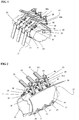
- Figures 1 to 3 illustrate three separate views of a single clamping device fitted to a pipe comprising three wrapping assemblies, each having a lever handle that is located in an unloaded neutral position in which the clamp is loosely fitted around the pipe.
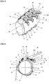
- Figures 4 to 6 illustrate the same views of the device shown in Figures 1 to 3 , save for the lever handles being pivoted into a loaded working position.
- the device shown in Figures 1 to 3 and the device shown in Figures 4 to 6 therefore comprise the same features and for the purpose of the complete description of the device, it is only necessary to describe the device in detail with reference to Figures 1 to 3 .
- the same reference numerals have been used on Figures 4 to 6 to label the same features of the device in Figures 1 to 3 .
- the clamp comprises a wrapping assembly in the form of a resiliently flexible base plate 20, looped straps 21 with an adjustment device in the form of a clasp 22, and an over centred lever mechanism 23.
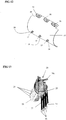
- the clamp is initially fitted to a pipe 24 of any size by disconnecting the straps 21 from the base plate 20 and placing the plate 20 over the rupture 25 in the pipe 24 in the manner shown in Figure 13 , the straps 21 are then connected to the base plate 20 as shown in Figure 14 and the free ends of the straps 20 pulled so as to fit the clamp around the pipe, and thereby provide a coarse level of adjustment.
- Adjustable wing nuts 26 on the over centre lever mechanism 23 can then be adjusted in the direction of the arrow shown in Figure 15 to provide a finer level of adjustment of the clamp.
- the over centre lever mechanism 23 can be pivoted in the direction of the arrow shown in Figure 16 from an unloaded neutral position to a loaded working position whereby the assembly is held taught around the pipe 24.
- the lever mechanism can be released and finer adjustment of the wing nuts 26 can be undertaken followed by movement of the handles back into a loaded working position.
- FIG. 1 to 3 The preferred embodiment shown in Figures 1 to 3 comprises a single flexible base plate 20 which is connected to three straps 21 and three over centre lever mechanisms 23.
- Figure 11 shows a perspective view of the plate 20 in isolation which forms part of the clamp shown in Figures 1 to 6 .
- the opposite upper edge of the plate 20 comprises three saddle formations 29 to which a handle 30 of the over centre lever mechanism 23 is pivotally mounted.
- the strapping includes a D-shaped formation 31 which can be connected and disconnected from each of the pegs 27 as desired.
- the layout of the strapping is such that the strapping extends from the clasp 22 to the D-shaped formation 31 through which it is threaded, and then looped back over a linkage 32 inter-connecting the strapping 21 to the lever mechanism 23 and then finally through the clasp 22.
- the clasp 22 includes a spring loaded flap 34 that is biased toward an abutment rod 33 which extends across the width of the clasp 22.
- the end of the flap 34 and the abutment rod 33 are arranged such that tension in the strapping 21 causes the flap 34 of the clasp 22 to move toward the abutment rod 33, thereby wedging the strapping 21 between the flap 34 and the abutment rod 33.
- the D-shaped formation 31 can be fitted to the pegs 27 of the plate 20 and the free end of each strapping 21 can be pulled to adjust the effective length of the strapping 21 wrapping about the piping 24 to a desired tension.
- the flap 34 is lifted to allow the strapping 21 to slide through the clasp 22. It would be appreciated that the clasp 22 and strapping 21 thereby provide a coarse level of adjustment for fitting the device to pipe 24.
- the handle 30 of the lever mechanism 23 has a V-shape that is pivotally mounted to the saddle formation 29 on the base plate 20 at pivot point 42.
- the V-shaped handle 30 comprises a major limb 30a which provides a grip by which the lever is operated and a minor limb 30b having a compartment in which an adjustor in the form of a screw threaded shaft 40 is slidably housed.
- Either side of the compartment has a slot 38 and ends of the linkage arms 36 are aligned with a fastening bolt 39 that extends through holes in the ends of a linkage arms 36, the slots 38 and holes in the screw threaded shaft 40.
- the fastening bolt 39 defines an axis about which the linkage arms 36 are pivotally connected to the lever 23 and, in particular, to the minor limb 30a thereof.
- a butterfly or wing nut 26 is fitted to an outside end of the screw threaded shaft 40 such that rotation of the wing nut 26 can move the pivot connection defined by the bolt 39 between the linkage arms 36 of the screw threaded shaft 40 in a direction along the slots 38 of the minor limb 30b of the handle 30. In other words, rotation of the wing nut 26 moves the pivot connection between the minor limb 30b of the lever 23 and the linkage arms 36 either towards or away from the pivot point 42 of the lever 23.
- the wing nut 26 In order to increase the tension of the clamp around the pipe, the wing nut 26 is rotated to move the pivot connection defined by bolt 39 in a direction away from the pivot point 42 of the lever 23. Conversely, in order to loosen the pressure of the clamp around the pipe 24, the wing nut is rotated so as to move the pivot connection defined by bolt 39 in a direction toward the pivot point 42 of the lever 23. It would be appreciated that the adjustable nature of the pivot connection between the linkage arms 36 and the lever 23 provides a second and finer level of adjustment of the tension of clamp about the pipe 24.
- each pair of linkage arms 36 are connected to each strapping 21 via a cam body 35 and linkage 32.
- each pair of linkage arms 36 are pivotally mounted to the cam body 35 via a fastening bolt that defines a pivot axis 37, which is best seen in Figures 3 and 6 as extending through an upper portion of the cam body 35.
- the linkage 32 essentially comprises two plates that are pivotally connected to the cam body 35 via a fastening bolt that defines a pivot axis 47.
- a further fastening bolt at the opposite end of the plates defines an axis 57 about which the strapping 21 is located.
- the pivot axis 37 of the linkage arms 36 to the cam body 35 extends through the cam body 35 at a spacing from piping 24 that is greater than the spacing of the pivot axis 47 the piping 24.
- each linkage arm 36 is curved such that when the lever 23 is located in a loaded position, the linkage arms 36 extend over the pivot point 42 at which fastening bolt pivotally mounts the lever 23 to the saddle formation 29 on the base plate 20.
- each linkage arm 35 is pivotally connected to the cam body 35 at pivot axis 37 that is displaced from the pipe 24 to reduce the degree of curvature and/or length of the linkage arms 35 that would otherwise be required.
- Figure 3 illustrates an end view of the clamp in which the lever 23 is located in an unloaded neutral position in which the wrapping assembly comprising base plate 20 and straps 21 are located in an initial circumferentially expanded state about the pipe 24.
- the straps 21 have been fitted and adjusted to an initial tension.
- the lever 23 is pivoted in the direction of the arrow shown in Figure 3 , so as to locate the lever 23 into a loaded working position as shown in Figures 4 to 6 .
- the wrapping assembly comprising base plate 20 and straps are located in a circumferentially contracted state about the pipe 24.
- the wing nuts 26 enable the size of the circumferentially contracted state of the clamp 23 about the pipe 24 to be gradually or progressively adjusted.
- the lever In moving the lever 23 in the direction of the arrow into the loaded working position, the lever passes through a peak load or tension position before reaching the loaded working position to provide an over centre effect.
- the over centre effect helps retain the lever mechanism in the loaded position and in order to move the lever into an unloaded position, an operator is required to move the lever 23 from loaded working position into a direction work the unloaded neutral position.
- the inside face of the base plate 20 may comprise any suitable material 43 for forming a seal with a rupture in the pipe.
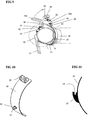
- FIGS 7 to 9 illustrate another preferred embodiment of the present invention.
- Figures 7 and 8 illustrate two clamps fitted to a pipe, wherein each clamp comprises a single base plate 20, a strap 20 with locking clasp 22 and a tensioning device in the form of an over centred lever mechanism 23.
- All of the features of the clamp shown in Figures 7 to 9 are substantially the same as the features of the clamps shown in Figures 1 to 6 save for each wrapping assembly comprising a single base plate 20 rather than a continuous base plate 20 interconnecting three straps 21.
- each clamp comprises looped strapping 21 with an adjustment device in the form of a claps 22 and an over centre lever mechanism 23.
- the strapping 21 is releasably attached to the base plate via a peg 27 on the base plate 20 and a D-shaped formation 31 that defines an end of the strapping 21 about which the strapping is looped in a U-shape.
- the over centre lever mechanism 23 includes a handle 30 having a V-shape that is pivotally mounted to the base plate 20 at pivot point 42 by a saddle formation 29 and bolt.
- the V-shaped handle includes a major limb 30b and minor limb 30a having an internal compartment in which a screw threaded shaft 40 having a butterfly wing nut 26 is fitted.
- the screw threaded shaft is pivotally connected to ends of a pair of curved linkage arms 36 and the other ends are connected to the cam block 35.
- the cam block 35 is connected to the straps 32 via a linkage 32. Operation of the clamp shown in Figures 7 to 9 is substantially the same as described with reference to the embodiment shown in Figures 1 to 6 .
- FIG 10 is a detailed view of the base plate 20 which comprises one of the pegs 27 for receiving the D-shaped ring of the strap 21 and one of the saddle formation 29 for pivotally mounting the lever mechanism.
- the inside face of each base plate 20 may comprise a sealing medium or alternatively, and in a situation in which multiple clamping devices are fitted to one pipe, an additional sealing medium 46, as best seen in Figures 8 and 9 , may extend between separate installations of the clamping device.
- Figure 12 is a side view of a base plate 20 having an alternative peg formation 27.
- the peg formation 27 has a leading ramp over which the D-shaped formation 31 can slide prior to being received by the recess 28.
- the leading ramp may have a rounded outer profile as shown in Figure 11 , or alternatively a progressively tapering profile.
- Figures 18 to 21 illustrate yet another embodiment that is the same, save for one major difference, as the embodiment shown in Figures 1 to 6 and 14 to 17.
- the notable difference is the inclusion of a locking mechanism for selectively locking the handle 30a in a loaded working position. When locked, the locking mechanism prevents the handle 30a from moving and being inadvertently or unintentionally released in a direction opposite to the direction of the arrow shown in Figure 20 .
- the locking mechanism is in the form of a strap 51 that is a continuation or extension of the strapping 21.
- the strap 51 is fitted to the end of the handle 30a and tensioned to prevent movement of the handle 30a.
- the locking mechanism also includes a clasp 52 to which the strap 51 is adjustably secured.
- the clasp 52 includes an eyelet formation which can be placed over the end of the handle 30a which may also have a corresponding lip to help retain the clasp 52 and strap 51 in position on the end of the handle 30a.
- the clasp 51 also includes a releasable flap and an abutment surface between which the strap 51 slides by pulling on the free end of the strap 51 to tension the strap 51 between the clasps 22 and 51 and thereby lock the handle 30a in the loaded working position.
- the locking mechanism is released by opening up the flap of the clasp 51.
- Figures 18 and 19 illustrate a sequence of steps involving positioning the clamp on a pipe and securing the D-shaped formations 31 to the pegs 27 of the base plates 20.
- the strapping 21 then undergoes initial tensioning by sliding the strapping 21 through the clasp 22.
- the wing nut can be rotated as shown in the Figure 18 to adjust the purchase provided by the over centre lever prior to engaging the lever.
- the lever, and in particular, the handle of the lever is moved in the direction shown by the arrow in Figure 19 to place the clamp into a loaded working position on the pipe.
- the clasp 52 is placed in the end of the handle 30a and the free end of the strap 51 pulled to tension the strapping 52 between the clasps 22 and 51, and thereby lock the handle 30a in a loaded working position until the flap of the clasp 52 is opened.
- each of the components of the clamping device may be made of a specialised material to facilitate the function of each domponent, it is envisage that the entire clamping device may be made from 316 grade stainless steel.
- the base plate, patch or band described in this specification may be made of, or include, either metallic materials such as stainless steel, or non-metallic materials such as fibreglass, fibrous materials and polymeric materials.
- the preferred embodiments provide a number of advantages over clamping devices presently available such as the following.
Landscapes
- Engineering & Computer Science (AREA)
- General Engineering & Computer Science (AREA)
- Mechanical Engineering (AREA)
- Clamps And Clips (AREA)
- Pipe Accessories (AREA)
- Basic Packing Technique (AREA)
Claims (15)
- Klemme zum Flicken eines Bruchs in einem Rohr, wobei die Klemme umfasst:
Eine Wickelanordnung, die ein Rohr (24) zumindest teilweise umschließen und auf einen Bruch (25) des Rohrs (24) positioniert werden kann; und eine Spannvorrichtung, die einen Hebelmechanismus (23) einschließt, die betätigbar ist, die Wickelanordnung um das Rohr (24) unter verschiedenen Spannungen zu platzieren, um zu ermöglichen, dass sich durch die Wickelanordnung auf den Bruch (25) angewandter Druck einstellen lässt, dadurch gekennzeichnet, dass die Wickelanordnung Gurtband (21) und eine Einstellvorrichtung (22) einschließt, die das Gurtband (21) reibschlüssig an irgendeiner gewünschten Stelle in Eingriff bringen kann, um selektiv die effektive Länge des Gurtbandes (21) einzustellen, die um das Rohr (24) gewickelt werden kann, wobei der Hebelmechanismus (23) ein Überlotpunkt-Hebelmechanismus ist, der aufweist,i) einen Griff (30), der drehbar mit der Wickelanordnung an einem ersten Drehpunkt (42) verbunden ist, undii) einen Verbindungsarm (36), der drehbar mit dem Griff an einem zweiten Drehpunkt verbunden ist und der zweite Drehpunkt über den ersten Drehpunkt verläuft, wenn der Hebelmechanismus (23) zwischen der belasteten Arbeitsposition, in welcher sich die Wickelanordnung in einem umfangsmäßig zusammengezogenen Zustand befindet und einer unbelasteten neutralen Position betätigt wird, in welcher sich die Wickelanordnung in einem umfangsmäßig expandierten Zustand befindet. - Klemme nach Anspruch 1, wobei das Gurtband (21) in einer Schleife angeordnet ist, in der sich das Gurtband (21) ab der Einstellvorrichtung (22) erstreckt und eine Schleife zurück und durch die Einstellvorrichtung (22) macht, sodass die effektive Länge des Gurtbands (21) durch zwei Unterabschnitte von Gurtband (21) gebildet wird.
- Klemme nach Anspruch 1, wobei der Hebelmechanismus (23) einen Versteller (40) zum Einstellen des Ansatzpunktes des Hebelmechanismus (23) einschließt und, seinerseits, ermöglicht, die Spannung im Gurt (21) wie gewünscht zu bewirken, und der Versteller betätigbar ist, die Position des zweiten Drehpunkts entweder entlang des Griffs (30) und/oder entlang des Verbindungsarms (36) in einem laufenden Fortschreiten zu verschieben, und vorzugsweise, die Last auf den Hebelmechanismus (23) zu erhöhen, der Versteller betätigbar ist, den zweiten Drehpunkt vom ersten Drehpunkt (42) des Griffs (30) zur Wickelanordnung zu verschieben und die Last auf den Hebelmechanismus (23) zu reduzieren, der Versteller betätigbar ist, den zweiten Drehpunkt in Richtung des ersten Drehpunkts (42) des Griffs (30) und der Wickelanordnung zu verschieben.
- Klemme nach Anspruch 3, wobei der Versteller einschließt:i) eine Welle (40), die innerhalb eines Gehäuses beweglich ist, das einen Teil des Griffs (30) bildet, und der Verbindungsarm (36) drehbar mit der Welle (40) verbunden ist, um den zweiten Drehpunkt zu bilden; undii) ein Anschlagstück, das sich entlang der Welle (40) bewegen lässt, und das Anschlagstück gegen das Gehäuse anstößt und betätigbar ist, den zweiten Drehpunkt der Verbindung zwischen dem Verbindungsarm (36) und dem Griff (30) entlang des Gehäuses zu verschieben.
- Klemme nach Anspruch 4, wobei die Welle (40) eine Welle mit Schraubengewinde ist und das Anschlagstück eine Flügelmutter (26) ist, die mit Finger einstellbar ist, wenn sich der Hebel in einer unbelasteten neutralen Position befindet.
- Klemme nach einem der Ansprüche 1 bis 5, wobei der Hebelmechanismus (23) eine Sperre einschließt, die betätigbar ist, zu verhindern, dass der Hebelmechanismus (23) unbeabsichtigt freigegeben oder aus der belasteten Arbeitsposition in die neutrale unbelastete Position bewegt wird.
- Klemme nach Anspruch 6, wobei die Sperre einen Gurt einschließt, der lösbar mit dem Hebelmechanismus (23) verbinden lässt, um den Hebelmechanismus (23) in der belasteten Arbeitsposition zu halten.
- Klemme nach einem der Ansprüche 1 bis 7, wobei der Verbindungsarm (36)zumindest ein nicht lineares Element umfasst, das geformt ist, sich über den ersten Drehpunkt (42) zu erstrecken, wenn sich der Griff (30) in einer belasteten Arbeitsposition befindet.
- Klemme nach einem der Ansprüche 1 bis 8, wobei der Hebelmechanismus (23) einen Nockenkörper (35) einschließt, der den Verbindungsarm (36) mit der Wickelanordnung verbindet, und der Nockenkörper (35) mit der Wickelanordnung an einem ersten Abstand vom Rohr (24) drehbar verbunden ist, an die er angebracht werden kann, und der Nockenkörper (35) mit dem Verbindungsarm (36) an einem zweiten Abstand vom Rohr (24) drehbar verbunden ist, der größer als der erste Abstand ist.
- Klemme nach einem der Ansprüche 2 bis 9, wobei die Einstellvorrichtung (22) eine Anlagefläche einschließt und das Gurtband (21) durch die Einstellvorrichtung (22) rutschen kann, um die Anlagefläche reibschlüssig an einem gewünschten Punkt entlang des Gurtbands (21) in Eingriff zu bringen, um die effektive Länge des Gurtbands (21) selektiv einzustellen.
- Klemme nach einem der Ansprüche 1 bis 10, wobei die Einstellvorrichtung (22) eine Verbindungsklammer mit einer offenen und schließbaren Klappe (34) einschließt und das Gurtband (21) zwischen der Klappe (34) und der Anlagefläche in einer geschlossenen Position eingeklemmt wird, wobei dadurch die effektive Länge des Gurtbands (21) gesichert wird, und vorzugsweise die Verbindungsklammer derartig konfiguriert ist, dass die Klappe (34) das durch die Verbindungsklammer laufende Gurtband (21) kontaktiert und Spannung im Gurtband (21) das Gurtband in einer Richtung durch die Verbindungsklammer zieht welche die Klappe (34) in Richtung der Anlagefläche bewegt, und dadurch das Gurtband (21) zwischen der Klappe (34) und der Anlagefläche einklemmt.
- Klemme nach einem der Ansprüche 1 bis 11, wobei die effektive Länge des Gurtbands (21) konfiguriert ist, zumindest einen Teil des Rohrs (24) zu umschließen und durch die Einstellvorrichtung (22) laufen, und sich ein Ende des Gurtbands (21) ab der Einstellvorrichtung (22) erstreckt und sich die effektive Länge durch Ziehen am Ende reduzieren lässt, das sich ab der Einstellvorrichtung (22) erstreckt, um das Gurtband (21) durch die Einstellvorrichtung (22) zu schieben.
- Klemme nach einem der Ansprüche 1 bis 12, wobei die Wickelanordnung lösbar mit der Spannvorrichtung verbunden ist, um das Installieren der Klemme, um das Rohr (24) zu gestatten.
- Klemme nach einem der Ansprüche 1 bis 13, wobei die Klemme einen Flicken zum Abdecken eines Bruchs (25) im Rohr (24) einschließt, und vorzugsweise der Flicken eine elastisch nachgiebige Metallplatte (20) oder ein Band einschließt, die/das um die Rohre verschiedener Durchmesser gebogen werden kann, und vorzugsweise der Flicken ein Dichtungsmittel auf der Innenseite des Flickens einschließt, um zu helfen, eine flüssigkeitsdichte oder fluiddichte Dichtung, wenn an ein Rohr (24) angebracht, zu schaffen, und vorzugsweise ist das Dichtungsmittel ein Material auf Gummi- oder Polymerbasis, und vorzugsweise lässt sich der Flicken, oder ein Teil davon, von der Klemme lösen, und vorzugsweise ist das Gurtband (21) mittels eines Sicherungsstifts (27) lösbar mit dem Flicken verbunden (27) ist, der sich ab dem Flicken nach außen erstreckt, der eine Ringformation an einem Ende des Gurtbands (21) aufnimmt.
- Klemme nach einem der Ansprüche 1 bis 14, wobei die Klemme zumindest zwei Wickelanordnungen umfasst, wobei jede das Gurtband (21) und die Einstellvorrichtung (22) zum Einstellen der effektiven Länge des Gurtbands (21) aufweist, die Wickelanordnungen außerdem einen einzelnen Flicken zur Abdeckung eines Bruchs (25) im Rohr (24) aufweisen, mit denen jedes Gurtband (21) lösbar verbunden ist, und wobei die zumindest zwei Spannvorrichtungen, und vorzugsweise die Zahl der Längen von Gurtband der Zahl von Spannvorrichtungen der Klemme entsprechen.
Applications Claiming Priority (2)
| Application Number | Priority Date | Filing Date | Title |
|---|---|---|---|
| AU2008905980A AU2008905980A0 (en) | 2008-11-19 | A clamp | |
| PCT/AU2009/001507 WO2010057256A1 (en) | 2008-11-19 | 2009-11-19 | A clamp and wrapping assembly for patching a pipe rupture |
Publications (3)
| Publication Number | Publication Date |
|---|---|
| EP2352945A1 EP2352945A1 (de) | 2011-08-10 |
| EP2352945A4 EP2352945A4 (de) | 2017-12-27 |
| EP2352945B1 true EP2352945B1 (de) | 2020-03-04 |
Family
ID=42197751
Family Applications (1)
| Application Number | Title | Priority Date | Filing Date |
|---|---|---|---|
| EP09827045.7A Active EP2352945B1 (de) | 2008-11-19 | 2009-11-19 | Klemme und wickelanordnung zum flicken eines rohrbruchs |
Country Status (6)
| Country | Link |
|---|---|
| US (1) | US8469060B2 (de) |
| EP (1) | EP2352945B1 (de) |
| AU (1) | AU2009317870B2 (de) |
| CA (1) | CA2744260C (de) |
| NZ (1) | NZ592937A (de) |
| WO (1) | WO2010057256A1 (de) |
Families Citing this family (9)
| Publication number | Priority date | Publication date | Assignee | Title |
|---|---|---|---|---|
| US8335292B2 (en) * | 2006-10-19 | 2012-12-18 | General Electric Company | Jet pump diffuser weld repair device and method |
| DE102010026665A1 (de) * | 2010-07-09 | 2012-05-03 | Dennis Jacobs | Vorrichtungen und Verfahren zur Abdichtung von Rohr/Schlauch-Leckagen |
| GB2505519A (en) * | 2012-09-04 | 2014-03-05 | Julian Sheard | Pipe leak repair device |
| EP2967674B1 (de) * | 2013-03-15 | 2024-02-21 | Biomet C.V. | Polyaxiales gehäuse für einen fixateuer externe |
| CN107214466A (zh) * | 2017-06-22 | 2017-09-29 | 五冶集团上海有限公司 | 用于管道制作对口的调整装置 |
| HRP20240638T1 (hr) * | 2018-01-19 | 2024-08-02 | Georg Fischer Wavin Ag | Cijevna stezaljka |
| WO2021133985A1 (en) | 2019-12-26 | 2021-07-01 | Romac Industries, Inc. | Pipeline connections |
| CN113685652B (zh) * | 2021-09-10 | 2023-05-05 | 江西省源河工程有限责任公司 | 一种水利工程用管道修补装置 |
| GB2619019B (en) * | 2022-05-23 | 2024-06-26 | Antonio Aguzzoli Marcos | A pipe repair device |
Family Cites Families (20)
| Publication number | Priority date | Publication date | Assignee | Title |
|---|---|---|---|---|
| US1027155A (en) * | 1911-09-05 | 1912-05-21 | Peter R Robbins | Attachment for hose. |
| US1071265A (en) * | 1912-09-19 | 1913-08-26 | Gustav Schlatter | Tilting autotruck. |
| US1290041A (en) * | 1916-07-07 | 1919-01-07 | Lars J Anderson | Hose-repair device. |
| FR584233A (fr) * | 1924-08-02 | 1925-02-02 | Fourreau arrêtant instantanément les fuites dans les tuyaux souples | |
| US1638269A (en) * | 1926-04-28 | 1927-08-09 | Arthur E Simpson | Emergency repair for pipes |
| US2182258A (en) * | 1937-07-26 | 1939-12-05 | Cecil E Kirk | Repair clamp |
| US3480043A (en) * | 1967-01-12 | 1969-11-25 | Ward M Proudfoot | Emergency leak clamp |
| US3591142A (en) * | 1968-07-09 | 1971-07-06 | Frank Lynn Hatcher | Tools for split pipe collars |
| US3916489A (en) * | 1974-04-22 | 1975-11-04 | Morris Coupling & Clamp Compan | Coupling |
| GB1523201A (en) * | 1976-02-03 | 1978-08-31 | Smith & Johnson Keighley Ltd | Ring clamps |
| US4083588A (en) * | 1977-02-11 | 1978-04-11 | Berger William L | Coupling |
| US4365393A (en) * | 1981-05-11 | 1982-12-28 | Mueller Co. | Single and multiple section pipe repair clamps |
| DE3546172A1 (de) * | 1985-12-27 | 1987-07-02 | Hoechst Ag | Leckageguertel |
| US5002093A (en) * | 1989-09-21 | 1991-03-26 | Connolly Jr Thomas | Repair patch for tubular fluid-containing vessel |
| SU1753179A1 (ru) * | 1990-10-02 | 1992-08-07 | Кооператив "Вертикаль" | Устройство дл ремонта трубопроводов |
| US6095784A (en) * | 1998-10-28 | 2000-08-01 | Wickizer; Antonio R. | Repair device for damaged shafts or journals |
| FR2787173B1 (fr) * | 1998-12-14 | 2001-03-09 | Alain Marcout | Manchon de reparation multi-diametres haute tolerance pour tous types de tuyauteries et canalisations |
| US6837522B2 (en) * | 2003-03-21 | 2005-01-04 | Cascade Waterworks Manufacturing Co. | Pipe repair clamp installation tool |
| US7314236B2 (en) * | 2003-03-21 | 2008-01-01 | Cascade Waterworks Manufacturing Co., Inc. | Adjustable pipe repair clamp installation tool |
| AU2006100649A4 (en) * | 2006-07-28 | 2006-11-16 | Aerofast Tiedowns (2001) Limited | Tie Down |
-
2009
- 2009-11-19 US US13/130,137 patent/US8469060B2/en active Active
- 2009-11-19 WO PCT/AU2009/001507 patent/WO2010057256A1/en not_active Ceased
- 2009-11-19 AU AU2009317870A patent/AU2009317870B2/en active Active
- 2009-11-19 CA CA2744260A patent/CA2744260C/en active Active
- 2009-11-19 NZ NZ592937A patent/NZ592937A/xx not_active IP Right Cessation
- 2009-11-19 EP EP09827045.7A patent/EP2352945B1/de active Active
Non-Patent Citations (1)
| Title |
|---|
| None * |
Also Published As
| Publication number | Publication date |
|---|---|
| AU2009317870B2 (en) | 2015-02-12 |
| CA2744260C (en) | 2016-04-26 |
| US20110290360A1 (en) | 2011-12-01 |
| NZ592937A (en) | 2013-08-30 |
| EP2352945A1 (de) | 2011-08-10 |
| WO2010057256A1 (en) | 2010-05-27 |
| AU2009317870A1 (en) | 2010-05-27 |
| CA2744260A1 (en) | 2010-05-27 |
| EP2352945A4 (de) | 2017-12-27 |
| US8469060B2 (en) | 2013-06-25 |
Similar Documents
| Publication | Publication Date | Title |
|---|---|---|
| CA2744260C (en) | A clamp and wrapping assembly for patching a pipe rupture | |
| US4969923A (en) | Safety latch | |
| US5727597A (en) | Point repair system for conduits | |
| US6971413B2 (en) | Apparatus for repairing an underwater pipe | |
| GB2448213A (en) | A method of installing a clamp on a tubular member | |
| AU2018260812B2 (en) | Apparatus and method for loading a pig into a pipeline | |
| US8266775B2 (en) | Apparatus, system, and method for installing clamps | |
| US20170045166A1 (en) | Flow through flange for a ship-to-ship cargo transfer flow line | |
| PL188117B1 (pl) | Opaska zaciskowa z zamkiem napinającym | |
| EP2805093B1 (de) | Verbesserte vorrichtung und verfahren zum einfügen von dichtungen | |
| US5954095A (en) | Apparatus and method for sealing a damaged pipe | |
| US7314236B2 (en) | Adjustable pipe repair clamp installation tool | |
| EP2941331B1 (de) | Verbesserte vorrichtung und verfahren zum einfügen von dichtungen | |
| US6837522B2 (en) | Pipe repair clamp installation tool | |
| US12078270B1 (en) | Dual cam lever hose clamp and methods of use thereof | |
| US6736367B2 (en) | Hose coupling lock for a valve and method of use of the same | |
| AU2006228040B1 (en) | A Clamp for Use With a Flexible Hose | |
| EP2208668B1 (de) | Dichtungsvorrichtung | |
| US20230151921A1 (en) | Apparatus and method for loading a pig into a pipeline with pipeline-engaging movable member, removable reducer, and hydraulic cylinder | |
| US12379056B1 (en) | Dual cam lever hose clamp | |
| CN219549928U (zh) | 钢丝绳拉紧器 | |
| US20150128393A1 (en) | Apparatus and Method for Insertion of Gaskets | |
| GB2050491A (en) | Fail Safe Clamp | |
| GB2474051A (en) | Clamping lever strap | |
| US20160221734A1 (en) | Protective casing for tool hosing and methods |
Legal Events
| Date | Code | Title | Description |
|---|---|---|---|
| PUAI | Public reference made under article 153(3) epc to a published international application that has entered the european phase |
Free format text: ORIGINAL CODE: 0009012 |
|
| 17P | Request for examination filed |
Effective date: 20110602 |
|
| AK | Designated contracting states |
Kind code of ref document: A1 Designated state(s): AT BE BG CH CY CZ DE DK EE ES FI FR GB GR HR HU IE IS IT LI LT LU LV MC MK MT NL NO PL PT RO SE SI SK SM TR |
|
| DAX | Request for extension of the european patent (deleted) | ||
| RA4 | Supplementary search report drawn up and despatched (corrected) |
Effective date: 20171123 |
|
| RIC1 | Information provided on ipc code assigned before grant |
Ipc: F16L 55/17 20060101ALI20171117BHEP Ipc: F16L 55/172 20060101AFI20171117BHEP |
|
| GRAP | Despatch of communication of intention to grant a patent |
Free format text: ORIGINAL CODE: EPIDOSNIGR1 |
|
| STAA | Information on the status of an ep patent application or granted ep patent |
Free format text: STATUS: GRANT OF PATENT IS INTENDED |
|
| INTG | Intention to grant announced |
Effective date: 20190527 |
|
| GRAJ | Information related to disapproval of communication of intention to grant by the applicant or resumption of examination proceedings by the epo deleted |
Free format text: ORIGINAL CODE: EPIDOSDIGR1 |
|
| STAA | Information on the status of an ep patent application or granted ep patent |
Free format text: STATUS: REQUEST FOR EXAMINATION WAS MADE |
|
| GRAP | Despatch of communication of intention to grant a patent |
Free format text: ORIGINAL CODE: EPIDOSNIGR1 |
|
| STAA | Information on the status of an ep patent application or granted ep patent |
Free format text: STATUS: GRANT OF PATENT IS INTENDED |
|
| INTC | Intention to grant announced (deleted) | ||
| INTG | Intention to grant announced |
Effective date: 20190925 |
|
| GRAS | Grant fee paid |
Free format text: ORIGINAL CODE: EPIDOSNIGR3 |
|
| GRAA | (expected) grant |
Free format text: ORIGINAL CODE: 0009210 |
|
| STAA | Information on the status of an ep patent application or granted ep patent |
Free format text: STATUS: THE PATENT HAS BEEN GRANTED |
|
| AK | Designated contracting states |
Kind code of ref document: B1 Designated state(s): AT BE BG CH CY CZ DE DK EE ES FI FR GB GR HR HU IE IS IT LI LT LU LV MC MK MT NL NO PL PT RO SE SI SK SM TR |
|
| REG | Reference to a national code |
Ref country code: GB Ref legal event code: FG4D |
|
| REG | Reference to a national code |
Ref country code: CH Ref legal event code: EP |
|
| REG | Reference to a national code |
Ref country code: AT Ref legal event code: REF Ref document number: 1240781 Country of ref document: AT Kind code of ref document: T Effective date: 20200315 |
|
| REG | Reference to a national code |
Ref country code: DE Ref legal event code: R096 Ref document number: 602009061371 Country of ref document: DE |
|
| REG | Reference to a national code |
Ref country code: IE Ref legal event code: FG4D |
|
| REG | Reference to a national code |
Ref country code: GR Ref legal event code: EP Ref document number: 20200401389 Country of ref document: GR Effective date: 20200716 |
|
| PG25 | Lapsed in a contracting state [announced via postgrant information from national office to epo] |
Ref country code: NO Free format text: LAPSE BECAUSE OF FAILURE TO SUBMIT A TRANSLATION OF THE DESCRIPTION OR TO PAY THE FEE WITHIN THE PRESCRIBED TIME-LIMIT Effective date: 20200604 Ref country code: FI Free format text: LAPSE BECAUSE OF FAILURE TO SUBMIT A TRANSLATION OF THE DESCRIPTION OR TO PAY THE FEE WITHIN THE PRESCRIBED TIME-LIMIT Effective date: 20200304 |
|
| REG | Reference to a national code |
Ref country code: NL Ref legal event code: MP Effective date: 20200304 |
|
| PG25 | Lapsed in a contracting state [announced via postgrant information from national office to epo] |
Ref country code: LV Free format text: LAPSE BECAUSE OF FAILURE TO SUBMIT A TRANSLATION OF THE DESCRIPTION OR TO PAY THE FEE WITHIN THE PRESCRIBED TIME-LIMIT Effective date: 20200304 Ref country code: SE Free format text: LAPSE BECAUSE OF FAILURE TO SUBMIT A TRANSLATION OF THE DESCRIPTION OR TO PAY THE FEE WITHIN THE PRESCRIBED TIME-LIMIT Effective date: 20200304 Ref country code: BG Free format text: LAPSE BECAUSE OF FAILURE TO SUBMIT A TRANSLATION OF THE DESCRIPTION OR TO PAY THE FEE WITHIN THE PRESCRIBED TIME-LIMIT Effective date: 20200604 Ref country code: HR Free format text: LAPSE BECAUSE OF FAILURE TO SUBMIT A TRANSLATION OF THE DESCRIPTION OR TO PAY THE FEE WITHIN THE PRESCRIBED TIME-LIMIT Effective date: 20200304 |
|
| REG | Reference to a national code |
Ref country code: LT Ref legal event code: MG4D |
|
| PG25 | Lapsed in a contracting state [announced via postgrant information from national office to epo] |
Ref country code: NL Free format text: LAPSE BECAUSE OF FAILURE TO SUBMIT A TRANSLATION OF THE DESCRIPTION OR TO PAY THE FEE WITHIN THE PRESCRIBED TIME-LIMIT Effective date: 20200304 |
|
| PG25 | Lapsed in a contracting state [announced via postgrant information from national office to epo] |
Ref country code: LT Free format text: LAPSE BECAUSE OF FAILURE TO SUBMIT A TRANSLATION OF THE DESCRIPTION OR TO PAY THE FEE WITHIN THE PRESCRIBED TIME-LIMIT Effective date: 20200304 Ref country code: EE Free format text: LAPSE BECAUSE OF FAILURE TO SUBMIT A TRANSLATION OF THE DESCRIPTION OR TO PAY THE FEE WITHIN THE PRESCRIBED TIME-LIMIT Effective date: 20200304 Ref country code: SM Free format text: LAPSE BECAUSE OF FAILURE TO SUBMIT A TRANSLATION OF THE DESCRIPTION OR TO PAY THE FEE WITHIN THE PRESCRIBED TIME-LIMIT Effective date: 20200304 Ref country code: SK Free format text: LAPSE BECAUSE OF FAILURE TO SUBMIT A TRANSLATION OF THE DESCRIPTION OR TO PAY THE FEE WITHIN THE PRESCRIBED TIME-LIMIT Effective date: 20200304 Ref country code: IS Free format text: LAPSE BECAUSE OF FAILURE TO SUBMIT A TRANSLATION OF THE DESCRIPTION OR TO PAY THE FEE WITHIN THE PRESCRIBED TIME-LIMIT Effective date: 20200704 Ref country code: PT Free format text: LAPSE BECAUSE OF FAILURE TO SUBMIT A TRANSLATION OF THE DESCRIPTION OR TO PAY THE FEE WITHIN THE PRESCRIBED TIME-LIMIT Effective date: 20200729 Ref country code: ES Free format text: LAPSE BECAUSE OF FAILURE TO SUBMIT A TRANSLATION OF THE DESCRIPTION OR TO PAY THE FEE WITHIN THE PRESCRIBED TIME-LIMIT Effective date: 20200304 Ref country code: CZ Free format text: LAPSE BECAUSE OF FAILURE TO SUBMIT A TRANSLATION OF THE DESCRIPTION OR TO PAY THE FEE WITHIN THE PRESCRIBED TIME-LIMIT Effective date: 20200304 Ref country code: RO Free format text: LAPSE BECAUSE OF FAILURE TO SUBMIT A TRANSLATION OF THE DESCRIPTION OR TO PAY THE FEE WITHIN THE PRESCRIBED TIME-LIMIT Effective date: 20200304 |
|
| REG | Reference to a national code |
Ref country code: AT Ref legal event code: MK05 Ref document number: 1240781 Country of ref document: AT Kind code of ref document: T Effective date: 20200304 |
|
| REG | Reference to a national code |
Ref country code: DE Ref legal event code: R097 Ref document number: 602009061371 Country of ref document: DE |
|
| PLBE | No opposition filed within time limit |
Free format text: ORIGINAL CODE: 0009261 |
|
| STAA | Information on the status of an ep patent application or granted ep patent |
Free format text: STATUS: NO OPPOSITION FILED WITHIN TIME LIMIT |
|
| PG25 | Lapsed in a contracting state [announced via postgrant information from national office to epo] |
Ref country code: IT Free format text: LAPSE BECAUSE OF FAILURE TO SUBMIT A TRANSLATION OF THE DESCRIPTION OR TO PAY THE FEE WITHIN THE PRESCRIBED TIME-LIMIT Effective date: 20200304 Ref country code: DK Free format text: LAPSE BECAUSE OF FAILURE TO SUBMIT A TRANSLATION OF THE DESCRIPTION OR TO PAY THE FEE WITHIN THE PRESCRIBED TIME-LIMIT Effective date: 20200304 Ref country code: AT Free format text: LAPSE BECAUSE OF FAILURE TO SUBMIT A TRANSLATION OF THE DESCRIPTION OR TO PAY THE FEE WITHIN THE PRESCRIBED TIME-LIMIT Effective date: 20200304 |
|
| 26N | No opposition filed |
Effective date: 20201207 |
|
| PG25 | Lapsed in a contracting state [announced via postgrant information from national office to epo] |
Ref country code: SI Free format text: LAPSE BECAUSE OF FAILURE TO SUBMIT A TRANSLATION OF THE DESCRIPTION OR TO PAY THE FEE WITHIN THE PRESCRIBED TIME-LIMIT Effective date: 20200304 Ref country code: PL Free format text: LAPSE BECAUSE OF FAILURE TO SUBMIT A TRANSLATION OF THE DESCRIPTION OR TO PAY THE FEE WITHIN THE PRESCRIBED TIME-LIMIT Effective date: 20200304 |
|
| PG25 | Lapsed in a contracting state [announced via postgrant information from national office to epo] |
Ref country code: MC Free format text: LAPSE BECAUSE OF FAILURE TO SUBMIT A TRANSLATION OF THE DESCRIPTION OR TO PAY THE FEE WITHIN THE PRESCRIBED TIME-LIMIT Effective date: 20200304 |
|
| REG | Reference to a national code |
Ref country code: CH Ref legal event code: PL |
|
| PG25 | Lapsed in a contracting state [announced via postgrant information from national office to epo] |
Ref country code: LU Free format text: LAPSE BECAUSE OF NON-PAYMENT OF DUE FEES Effective date: 20201119 |
|
| REG | Reference to a national code |
Ref country code: BE Ref legal event code: MM Effective date: 20201130 |
|
| PG25 | Lapsed in a contracting state [announced via postgrant information from national office to epo] |
Ref country code: LI Free format text: LAPSE BECAUSE OF NON-PAYMENT OF DUE FEES Effective date: 20201130 Ref country code: CH Free format text: LAPSE BECAUSE OF NON-PAYMENT OF DUE FEES Effective date: 20201130 |
|
| PG25 | Lapsed in a contracting state [announced via postgrant information from national office to epo] |
Ref country code: IE Free format text: LAPSE BECAUSE OF NON-PAYMENT OF DUE FEES Effective date: 20201119 |
|
| PGFP | Annual fee paid to national office [announced via postgrant information from national office to epo] |
Ref country code: GR Payment date: 20210830 Year of fee payment: 13 |
|
| PGFP | Annual fee paid to national office [announced via postgrant information from national office to epo] |
Ref country code: FR Payment date: 20211006 Year of fee payment: 13 |
|
| PG25 | Lapsed in a contracting state [announced via postgrant information from national office to epo] |
Ref country code: TR Free format text: LAPSE BECAUSE OF FAILURE TO SUBMIT A TRANSLATION OF THE DESCRIPTION OR TO PAY THE FEE WITHIN THE PRESCRIBED TIME-LIMIT Effective date: 20200304 Ref country code: MT Free format text: LAPSE BECAUSE OF FAILURE TO SUBMIT A TRANSLATION OF THE DESCRIPTION OR TO PAY THE FEE WITHIN THE PRESCRIBED TIME-LIMIT Effective date: 20200304 Ref country code: CY Free format text: LAPSE BECAUSE OF FAILURE TO SUBMIT A TRANSLATION OF THE DESCRIPTION OR TO PAY THE FEE WITHIN THE PRESCRIBED TIME-LIMIT Effective date: 20200304 |
|
| PG25 | Lapsed in a contracting state [announced via postgrant information from national office to epo] |
Ref country code: MK Free format text: LAPSE BECAUSE OF FAILURE TO SUBMIT A TRANSLATION OF THE DESCRIPTION OR TO PAY THE FEE WITHIN THE PRESCRIBED TIME-LIMIT Effective date: 20200304 |
|
| PG25 | Lapsed in a contracting state [announced via postgrant information from national office to epo] |
Ref country code: BE Free format text: LAPSE BECAUSE OF NON-PAYMENT OF DUE FEES Effective date: 20201130 |
|
| PG25 | Lapsed in a contracting state [announced via postgrant information from national office to epo] |
Ref country code: GR Free format text: LAPSE BECAUSE OF NON-PAYMENT OF DUE FEES Effective date: 20230609 |
|
| PG25 | Lapsed in a contracting state [announced via postgrant information from national office to epo] |
Ref country code: FR Free format text: LAPSE BECAUSE OF NON-PAYMENT OF DUE FEES Effective date: 20221130 |
|
| PGFP | Annual fee paid to national office [announced via postgrant information from national office to epo] |
Ref country code: DE Payment date: 20251126 Year of fee payment: 17 |
|
| PGFP | Annual fee paid to national office [announced via postgrant information from national office to epo] |
Ref country code: GB Payment date: 20251020 Year of fee payment: 17 |