EP2352910B1 - Elektromagnetische nockenwellen-verstellvorrichtung - Google Patents
Elektromagnetische nockenwellen-verstellvorrichtung Download PDFInfo
- Publication number
- EP2352910B1 EP2352910B1 EP10719727A EP10719727A EP2352910B1 EP 2352910 B1 EP2352910 B1 EP 2352910B1 EP 10719727 A EP10719727 A EP 10719727A EP 10719727 A EP10719727 A EP 10719727A EP 2352910 B1 EP2352910 B1 EP 2352910B1
- Authority
- EP
- European Patent Office
- Prior art keywords
- unit
- magnetic field
- armature
- permanent magnet
- field detection
- Prior art date
- Legal status (The legal status is an assumption and is not a legal conclusion. Google has not performed a legal analysis and makes no representation as to the accuracy of the status listed.)
- Active
Links
Images

Classifications
-
- F—MECHANICAL ENGINEERING; LIGHTING; HEATING; WEAPONS; BLASTING
- F01—MACHINES OR ENGINES IN GENERAL; ENGINE PLANTS IN GENERAL; STEAM ENGINES
- F01L—CYCLICALLY OPERATING VALVES FOR MACHINES OR ENGINES
- F01L13/00—Modifications of valve-gear to facilitate reversing, braking, starting, changing compression ratio, or other specific operations
- F01L13/0015—Modifications of valve-gear to facilitate reversing, braking, starting, changing compression ratio, or other specific operations for optimising engine performances by modifying valve lift according to various working parameters, e.g. rotational speed, load, torque
- F01L13/0036—Modifications of valve-gear to facilitate reversing, braking, starting, changing compression ratio, or other specific operations for optimising engine performances by modifying valve lift according to various working parameters, e.g. rotational speed, load, torque the valves being driven by two or more cams with different shape, size or timing or a single cam profiled in axial and radial direction
-
- F—MECHANICAL ENGINEERING; LIGHTING; HEATING; WEAPONS; BLASTING
- F01—MACHINES OR ENGINES IN GENERAL; ENGINE PLANTS IN GENERAL; STEAM ENGINES
- F01L—CYCLICALLY OPERATING VALVES FOR MACHINES OR ENGINES
- F01L1/00—Valve-gear or valve arrangements, e.g. lift-valve gear
- F01L1/34—Valve-gear or valve arrangements, e.g. lift-valve gear characterised by the provision of means for changing the timing of the valves without changing the duration of opening and without affecting the magnitude of the valve lift
-
- F—MECHANICAL ENGINEERING; LIGHTING; HEATING; WEAPONS; BLASTING
- F01—MACHINES OR ENGINES IN GENERAL; ENGINE PLANTS IN GENERAL; STEAM ENGINES
- F01L—CYCLICALLY OPERATING VALVES FOR MACHINES OR ENGINES
- F01L1/00—Valve-gear or valve arrangements, e.g. lift-valve gear
- F01L1/46—Component parts, details, or accessories, not provided for in preceding subgroups
-
- H—ELECTRICITY
- H01—ELECTRIC ELEMENTS
- H01F—MAGNETS; INDUCTANCES; TRANSFORMERS; SELECTION OF MATERIALS FOR THEIR MAGNETIC PROPERTIES
- H01F7/00—Magnets
- H01F7/06—Electromagnets; Actuators including electromagnets
- H01F7/08—Electromagnets; Actuators including electromagnets with armatures
- H01F7/121—Guiding or setting position of armatures, e.g. retaining armatures in their end position
- H01F7/122—Guiding or setting position of armatures, e.g. retaining armatures in their end position by permanent magnets
-
- H—ELECTRICITY
- H01—ELECTRIC ELEMENTS
- H01F—MAGNETS; INDUCTANCES; TRANSFORMERS; SELECTION OF MATERIALS FOR THEIR MAGNETIC PROPERTIES
- H01F7/00—Magnets
- H01F7/06—Electromagnets; Actuators including electromagnets
- H01F7/08—Electromagnets; Actuators including electromagnets with armatures
- H01F7/16—Rectilinearly-movable armatures
- H01F7/1638—Armatures not entering the winding
- H01F7/1646—Armatures or stationary parts of magnetic circuit having permanent magnet
-
- F—MECHANICAL ENGINEERING; LIGHTING; HEATING; WEAPONS; BLASTING
- F01—MACHINES OR ENGINES IN GENERAL; ENGINE PLANTS IN GENERAL; STEAM ENGINES
- F01L—CYCLICALLY OPERATING VALVES FOR MACHINES OR ENGINES
- F01L13/00—Modifications of valve-gear to facilitate reversing, braking, starting, changing compression ratio, or other specific operations
- F01L13/0015—Modifications of valve-gear to facilitate reversing, braking, starting, changing compression ratio, or other specific operations for optimising engine performances by modifying valve lift according to various working parameters, e.g. rotational speed, load, torque
- F01L13/0036—Modifications of valve-gear to facilitate reversing, braking, starting, changing compression ratio, or other specific operations for optimising engine performances by modifying valve lift according to various working parameters, e.g. rotational speed, load, torque the valves being driven by two or more cams with different shape, size or timing or a single cam profiled in axial and radial direction
- F01L2013/0052—Modifications of valve-gear to facilitate reversing, braking, starting, changing compression ratio, or other specific operations for optimising engine performances by modifying valve lift according to various working parameters, e.g. rotational speed, load, torque the valves being driven by two or more cams with different shape, size or timing or a single cam profiled in axial and radial direction with cams provided on an axially slidable sleeve
-
- F—MECHANICAL ENGINEERING; LIGHTING; HEATING; WEAPONS; BLASTING
- F01—MACHINES OR ENGINES IN GENERAL; ENGINE PLANTS IN GENERAL; STEAM ENGINES
- F01L—CYCLICALLY OPERATING VALVES FOR MACHINES OR ENGINES
- F01L9/00—Valve-gear or valve arrangements actuated non-mechanically
- F01L9/20—Valve-gear or valve arrangements actuated non-mechanically by electric means
-
- H—ELECTRICITY
- H01—ELECTRIC ELEMENTS
- H01F—MAGNETS; INDUCTANCES; TRANSFORMERS; SELECTION OF MATERIALS FOR THEIR MAGNETIC PROPERTIES
- H01F7/00—Magnets
- H01F7/06—Electromagnets; Actuators including electromagnets
- H01F7/08—Electromagnets; Actuators including electromagnets with armatures
- H01F7/18—Circuit arrangements for obtaining desired operating characteristics, e.g. for slow operation, for sequential energisation of windings, for high-speed energisation of windings
- H01F7/1844—Monitoring or fail-safe circuits
- H01F2007/185—Monitoring or fail-safe circuits with armature position measurement
Definitions
- the present invention relates to an electromagnetic camshaft adjusting device according to the preamble of the main claim.
- Such a device is well-known from the prior art and serves the so-called return actuator, wherein, for example, a detected in the de-energized state of the coil unit and evaluated induction signal is evaluated according to the camshaft position moving armature unit at the terminals of the coil unit.
- Such a device shows, for example, the DE 10 2006 035 225 A1 the applicant.
- camshaft adjustment monitoring is combined with an already existing knock sensor electronics, combined with a lambda probe electronics, or a Crankshaft acceleration is detected and evaluated.
- the induction voltage measured in the generic manner depends on factors such as the speed of movement (this in turn depends on the engine speed), the current ambient temperature, soiling, etc., so that a desired reliable detection of faulty circuits is not possible guaranteed in every operating condition.
- Object of the present invention is therefore to provide a simple, reliable and with little manufacturing technology and evaluation effort to realize camshaft adjusting device, in which a current camshaft adjustment state or a current position of the camshaft adjustment causing armature including driven actuator are reliably determined can.
- the housing or carrier unit accommodating the camshaft adjusting device is associated with stationary magnetic field detection means which interact with permanent magnet means movable in accordance with the armature and / or actuator movement such that in all operating states, namely the energization state of the coil unit and the non-energized state of the coil unit, by this magnetic field detection an axial position determination is possible.
- the magnetic field detection means are advantageously realized as separated from the coil unit, separate sensor means which are formed in an otherwise known manner and advantageously in the context of preferred developments as Hall sensors, GMR or AMR sensors realized sensor means.
- the armature unit itself has a permanent magnet unit in the context of the electromagnetic adjustment, which advantageously performs an advancing movement of the armature unit (and actuating unit) by energizing the coil unit.
- This movement of the permanent magnet unit in the armature unit can then be determined in a very simple way by the magnetic field sensor, in particular if it is provided adjacent to the permanent magnet unit and a change in the permanent magnetic field can thereby be detected (variable in movement).
- the ram unit is wholly or partially permanent magnetic, in which connection, but also in the design of a permanent magnet on the armature unit, further advantageous, a connection between actuator (designed as Ram unit) and anchor unit Permanent magnetic adhesion between these units releasably designed.
- the at least one magnetic field sensor for realizing the magnetic field detection means is provided at a stationary position in the housing or carrier unit, it being meaningful for production and trouble-free operation, this sensor (possibly together with other stationary units of the device) in a otherwise known manner by means of a polymeric potting material or the like to shed moisture and dirt.
- a (relative) position of the magnetic field sensor unit in the housing can also be fixed in this way, for example by virtue of the fact that the potting compound completely or partially encloses the sensor.
- FIG. 1 illustrates the structure and operation principle of the electromagnetic camshaft adjusting device according to a first embodiment of the invention:
- a stationary coil unit 10 is provided, which is formed around a stationary core 12 around.
- an anchor unit 14 In these stationary units in the axial direction (ie longitudinal direction in the FIG. 1 Movably mounted is an anchor unit 14 with ansaftender plunger unit 16, which with its engagement-side end 18 in an otherwise known manner for cooperation with a groove or the like. a camshaft adjustment is formed.
- the armature unit 14 has a permanent magnet unit 20 which axially magnetises in the manner shown and faces the core unit in such a way that the armature unit together with the seated tappet unit 16 (this is either fixed or by adhesive force of the permanent magnet unit 20 detachably on in response to an energizing of the coil unit 10 held the permanent magnet unit) in the axial direction (ie in the FIG. 1 downwards) is moved.
- the permanent magnet unit 20 is associated with a stationary sensor unit 22 (suitable in the housing not shown in the figures), which detects the permanent magnetic field and, suitably realized as a Hall element, detect this magnetic field and its change by movement of the armature unit 14 and a subsequent electronic evaluation can perform.
- a stationary sensor unit 22 suitable in the housing not shown in the figures
- this principal realization form makes it possible to generate a correspondingly positionally variable signal along a suitable movement stroke of the armature unit 14, which is advantageous for every energization time of the coil unit-advantageous compared to the known principle of detecting an induction voltage at the coil ends of the unit 10 in the de-energized state 10 can perform a position detection and can detect the position, even if the anchor unit does not move, so stands still at a corresponding position.
- FIG. 1 (as well as the FIGS. 2 to 5 ) merely show the schematic interaction for realizing the basic principle of the invention; the concrete realization of an embodiment is related with the FIGS. 6 to 8 explained, furthermore, in view of a favorable realization of the in the FIGS. 1 to 5 shown
- FIGS. 1 to 5 Aktorik to the disclosed patent application DE 20 2008 010 301 the Applicant referred to, which should be considered as part of the present invention with regard to the design of a surrounding housing, the core, yoke and anchor unit and the coil unit as belonging to the invention.
- FIG. 2 shows the embodiment of FIG. 2 in which (here in a common housing, not shown) a pair of actuators, each consisting of coil unit 10, core unit 12 and armature units 14a and 14b is provided side by side; especially in the context of a camshaft adjustment devices are often used with two plungers, wherein a first plunger 16a is used to move the camshaft adjustment mechanism in a first position and an axially parallel driven second plunger 16b is used to return to the starting position to effect.
- a pair of actuators each consisting of coil unit 10, core unit 12 and armature units 14a and 14b is provided side by side; especially in the context of a camshaft adjustment devices are often used with two plungers, wherein a first plunger 16a is used to move the camshaft adjustment mechanism in a first position and an axially parallel driven second plunger 16b is used to return to the starting position to effect.
- a first plunger 16a is used to move the camshaft adjustment mechanism in a first position
- FIG. 2 also shows two sensors 22a and 22b, which, analogously to the representation of FIG. 1 (In this regard, corresponding reference numerals are used), a respective anchor unit or ram unit are assigned.
- FIG. 3 shows a variant of the implementation of the FIG. 2 (and again with comparable assemblies corresponding reference numerals used).
- the device of the FIG. 3 a common sensor unit 22c, which, compare the cut at the height of the sensor radial section of the FIG. 4 is arranged approximately symmetrically between the two anchor units (respectively of the respective permanent magnets 20), such that a radial distance influencing the measured field strength is equal to both permanent magnet arrangements 20 in the sectional plane and at the same axial position of the anchor units 14a, 14b is equal in absolute value Magnetic field, but in the respective direction diverging magnetic field generated.
- FIG. 1 Surrounded by a cylindrical housing shell 30 and encapsulated by a plastic potting material 32 is a coil unit including core unit (recognizable is only a planar end portion 34, which protrudes from the encapsulation) provided; in a manner not shown in detail, the coil unit is electrically contacted and the connecting cable for external contacting led to an integrally ansitzenden connector portion 36.
- core unit recognizable is only a planar end portion 34, which protrudes from the encapsulation
- a cylindrical sensor unit 38 is mounted in the housing, that it is enclosed in approximately half of the potting material 32 and with their (in the FIG. 6 lower) half protrudes into a cavity 40 in the housing 30.
- axially relatively movable to the core 34 protrudes from the opposite side of an armature unit 42 which centrally carries a disc-shaped permanent magnet 44, which interacts in the manner described above without contact with the sensor unit 38 so that in axial (ie in the FIG. 6 vertical) movement of the armature unit, the stationary sensor unit 38 detects a changing permanent magnetic field and feeds it (in a manner not shown) to a subsequent electronic processing.
- the housing 30 is closed on the bottom side with an end piece 46, in which a ram unit 48 is guided; this contacts at one end (in the upper end) the armature unit 42 or is part of this, in the opposite end region of the camshaft adjusting engagement portion 18 is formed.
- Channels 50 in the bottom piece 46 serve for venting and a circumferential radial seal 52 of the seal against a receiving housing of Stellpartners, eg the camshaft housing.
- FIG. 8 illustrates in this context once again low, as the potting compound 32 is provided in the housing shell 30 and the sensor unit 38 reliably, dirt-protected and easily mounted at their relative position to the permanent magnet 44 and the anchor unit 42 holds.
- the present invention is not limited to the described embodiments. Although it is advantageous to use a standard permanent magnet detector principle (Hall, GMR or AMR) for the sensor unit, other magnetic detection options are also conceivable.
- a standard permanent magnet detector principle Hall, GMR or AMR
- the present invention is favorable as a camshaft adjusting device, but the principle of electromagnetic actuators, in particular in conjunction with a permanent magnet on the armature and a stationary magnetic field detection of this armature, is suitable for basically any control tasks, which in the manner described advantageous and Any operating situations need reliable detection of the anchor or plunger position.
Landscapes
- Engineering & Computer Science (AREA)
- Physics & Mathematics (AREA)
- Electromagnetism (AREA)
- Mechanical Engineering (AREA)
- General Engineering & Computer Science (AREA)
- Power Engineering (AREA)
- Valve Device For Special Equipments (AREA)
- Transmission And Conversion Of Sensor Element Output (AREA)
Description
- Die vorliegende Erfindung betrifft eine elektromagnetische Nockenwellen-Verstellvorrichtung nach dem Oberbegriff des Hauptanspruchs.
- Eine derartige Vorrichtung ist aus dem Stand der Technik allgemein bekannt und dient der sogenannten Rückstellerfassung, wobei beispielsweise ein in unbestromtem Zustand der Spuleneinheit erfasstes und ausgewertetes Induktionssignal der sich entsprechend der Nockenwellenstellung bewegenden Ankereinheit an den Anschlussklemmen der Spuleneinheit ausgewertet wird. Eine derartige Vorrichtung zeigt beispielsweise die
DE 10 2006 035 225 A1 der Anmelderin. - Darüber hinaus gibt es weitere Möglichkeiten, eine korrekte Funktion einer Nockenwellenverstellung zu überwachen, wobei jedoch auch dies indirekt erfolgt, indem etwa eine derartige Nockenwellen-Verstellungsüberwachung mit einer ohnehin vorhandenen Klopfsensor-Elektronik kombiniert wird, mit einer Lambda-Sondenelektronik kombiniert wird, oder aber eine Kurbelwellenbeschleunigung erfasst und ausgewertet wird.
- All diesen Vorgehensweisen ist jedoch gemeinsam, dass eine Fehlfunktion aus dem jeweiligen Signal nur schwer zu ermitteln ist und entsprechend eine sehr aufwändige (und potenziell unzuverlässige) elektronische Signalauswertung zum Ermitteln der konkreten Stößelposition (Stelleinheit) für die Nockenwelle notwendig ist. Hinzu kommt, dass bei der als gattungsbildend herangezogenen Induktionstechnologie prinzipbedingt nur eine Bewegung des Stößels bzw. der Ankereinheit ermittelt werden kann, nicht jedoch dessen/deren Stillstandsposition; insbesondere ist es mit Mitteln der Auswertung einer Induktions-Spulenspannung nicht möglich, eine (stehende) Endposition des in die Nockenwelle eingreifenden Stößels (Stelleinheit) zuverlässig zu erfassen.
- Als weiteres potenzielles technisches Problem ergibt sich, dass die in der gattungsgemäßen Weise gemessene Induktionsspannung von Faktoren wie Bewegungsgeschwindigkeit (dies ist wiederum abhängig von der Motordrehzahl), der aktuellen Umgebungstemperatur, Verschmutzungen usw. abhängig ist, so dass damit eine gewünschte sichere Erkennung von Fehlschaltungen nicht in jedem Betriebszustand gewährleistet ist.
- Aufgabe der vorliegenden Erfindung ist es daher, eine einfache, zuverlässige und mit geringem herstellungstechnischen und Auswertungsaufwand zu realisierende Nockenwellen-Verstellvorrichtung zu schaffen, bei welcher ein aktueller Nockenwellen-Verstellzustand bzw. eine aktuelle Position eines die Nockenwellenverstellung bewirkenden Ankers samt dadurch angetriebener Stelleinheit zuverlässig ermittelt werden kann.
- Die Aufgabe wird durch die Vorrichtung mit den Merkmalen des Hauptanspruchs gelöst; vorteilhafte Weiterbildungen der Erfindung sind in den Unteransprüchen beschrieben.
- In erfindungsgemäß vorteilhafter Weise sind der die Nockenwellen-Verstellvorrichtung aufnehmenden Gehäuse- bzw. Trägereinheit stationäre Magnetfeld-Detektionsmittel zugeordnet, welche mit entsprechend der Anker- und/oder Stelleinheit-Bewegung beweglichen Permanentmagnetmitteln so zusammenwirken, dass in allen Betriebszuständen, nämlich dem Bestromungszustand der Spuleneinheit und dem Nicht-Bestromungszustand der Spuleneinheit, durch diese Magnetfeld-Detektion eine axiale Positionsbestimmung möglich ist. Dies bedeutet, dass erfindungsgemäß eine Abkehr vom gattungsgemäßen Prinzip der Erfassung einer Spulen-Induktionsspannung im unbestromten Zustand erfolgt; vielmehr sind vorteilhaft die Magnetfeld-Detektionsmittel als von der Spuleneinheit getrennte, separate Sensormittel realisiert, welche in ansonsten bekannter Weise und vorteilhaft im Rahmen bevorzugter Weiterbildungen als Hall-Sensoren, GMR- oder AMR-Sensoren realisierte Sensormittel ausgebildet sind.
- Besonders bevorzugt, da konstruktiv einfach, ist dabei die Realisierung gemäß einer bevorzugten Ausführungsform, bei welcher die Ankereinheit im Rahmen der elektromagnetischen Verstellvorrichtung selbst eine Permanentmagneteinheit aufweist, welche vorteilhaft etwa durch Bestromen der Spuleneinheit eine das Antreiben der Ankereinheit (und Stelleinheit) bewirkende Vorschubbewegung ausführt. Diese Bewegung der Permanentmagneteinheit in der Ankereinheit lässt sich dann auf sehr einfache Weise von dem Magnetfeld-Sensor ermitteln, insbesondere wenn dieser der Permanentmagneteinheit benachbart vorgesehen ist und dadurch (bewegungsveränderlich) eine Veränderung des Permanentmagnetfeldes detektiert werden kann.
- Ergänzend oder alternativ ist im Rahmen bevorzugter Ausführungen der Erfindung vorgesehen, dass die Stößeleinheit ganz oder teilweise permanentmagnetisch ausgebildet ist, wobei es in diesem Zusammenhang, jedoch auch bei der Ausgestaltung eines Permanentmagneten an der Ankereinheit, weiter vorteilhaft ist, eine Verbindung zwischen Stelleinheit (ausgebildet als Stößeleinheit) und Ankereinheit durch permanentmagnetische Haftwirkung zwischen diesen Einheiten lösbar auszugestalten.
- Im Rahmen der Erfindung ist der mindestens eine Magnetfeld-Sensor zur Realisierung der Magnetfeld-Detektionsmittel an einer stationären Position in der Gehäuse- oder Trägereinheit vorgesehen, wobei -- bedeutsam für Fertigung und störungsfreien Betrieb -- es sinnvoll ist, diesen Sensor (ggf. zusammen mit weiteren stationären Aggregaten der Vorrichtung) in ansonsten bekannter Weise mittels eines polymeren Vergussmaterials oder dergleichen feuchtigkeits- und schmutzgeschützt zu vergießen. Geeignet kann dadurch auch eine (Relativ-) Position der Magnetfeld-Sensoreinheit im Gehäuse fixiert werden, etwa dadurch, dass die Vergussmasse den Sensor ganz oder teilweise umschließt.
- Im Rahmen der elektronischen Auswertung ist es dabei einerseits möglich und vorgesehen, eine binäre bzw. digitale Magnetfeld-Detektion durch geeignete Ausgestaltung eines (positionsabhängigen) Schwellwertes vorzunehmen, andererseits ist es im Rahmen bevorzugter Ausführungsformen der Erfindung vorgesehen, entsprechend verschiedene detektierbare axiale oder radiale Parameter eines Permanentmagnetfeldes geeignet und bevorzugt kontinuierlich auszuwerten, so dass etwa eine vollständige Verfolgung des von der Ankereinheit (bzw. der Stelleinheit) beschriebenen axialen Weges möglich ist.
- Im Rahmen bevorzugter Ausführungsbeispiele liegt es dabei einerseits, bei der Verwendung einer Mehrzahl von angetriebenen Stößeleinheiten (z.B. im Rahmen einer gemeinsamen Gehäuseeinheit) eine entsprechende Mehrzahl von zugeordneten Sensoreinheiten vorzusehen; alternativ ist es möglich, eine einzige, gemeinsame Sensoreinheit (vorteilhaft etwa asymmetrisch bezogen auf die radiale Anordnung) so auszugestalten, dass durch Beobachtung der jeweiligen Magnetfelder hier eine saubere Diskriminierung erfolgen und gemeinsame Erfassung mit lediglich einer Sensoreinheit möglich ist.
- Weitere Vorteile, Merkmale und Einzelheiten ergeben sich aus der nachfolgenden Beschreibung bevorzugter Ausführungsbeispiele sowie anhand der Zeichnungen; diese zeigen in:
- Figur 1:
- eine Schemaansicht des Aufbaus der elektromagnetischen Nockenwellen-Verstellvorrichtung gemäß einer ersten Ausführungsform mit einer Ankereinheit und einer dieser zugeordneten Stößeleinheit;
- Figur 2:
- eine Vorrichtung analog
Figur 1 mit einem Paar von nebeneinander vorgesehenen, separat voneinander bewegbaren Ankereinheiten mit jeweils einer aufsitzenden Stößeleinheit und jeweils einer zugeordneten Sensoreinheit; - Figur 3:
- eine weitere Ausführungsform analog der
Figur 2 , jedoch mit einer für beide Ankereinheiten bzw. Stößeleinheiten gemeinsam vorgesehenen Sensoreinheit; - Figur 4:
- eine Schnittansicht senkrecht zur Bewegungs-Längsachse der Anordnung gemäß
Figur 3 mit der gezeigten, im Hinblick auf beide Anker-bzw. Stößeleinheiten symmetrisch angeordneten Sensoreinheit; - Figur 5:
- eine Variante der Darstellung gemäß
Figur 4 mit asymmetrisch angeordneter Sensoreinheit, d.h. unterschiedlicher radialer Entfernung der Sensoreinheit zu einer Anker- bzw. Stößeleinheit relativ zur anderen Anker- bzw. Stößeleinheit; - Figur 6:
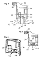
- einen Längsschnitt durch eine konkrete Realisierungsform der elektromagnetischen Nockenwellen-Verstellvorrichtung zur Realisierung des Schemas der
Figur 1 ; - Figur 7:
- einen Längsschnitt durch den oberen Gehäuseabschnitt des Ausführungsbeispiels der
Figur 6 und - Figur 8:
- eine Perspektivdarstellung eines Ausschnitts aus der
Figur 7 zum Verdeutlichen der Dreidimensionalität. -
Figur 1 verdeutlicht den Aufbau und das Funktionsprinzip der elektromagnetischen Nockenwellen-Verstellvorrichtung gemäß einer ersten Ausführungsform der Erfindung: In einer (nicht gezeigten) Gehäuseeinheit ist eine stationäre Spuleneinheit 10 vorgesehen, welche um einen stationären Kern 12 herum gebildet ist. In diesen stationären Einheiten in axialer Richtung (d.h. Längsrichtung in derFigur 1 ) bewegbar gelagert ist eine Ankereinheit 14 mit ansitzender Stößeleinheit 16, welche mit ihrem eingriffseitigen Ende 18 in ansonsten bekannter Weise zum Zusammenwirken mit einer Nut od.dgl. einer Nockenwellenverstellung ausgebildet ist. - Die Ankereinheit 14 weist eine Permanentmagneteinheit 20 auf, welche in der gezeigten Weise axial magnetisiert und so der Kerneinheit gegenübersteht, dass als Reaktion auf ein Bestromen der Spuleneinheit 10 die Ankereinheit samt ansitzender Stößeleinheit 16 (diese ist entweder fest oder durch Haftkraft der Permanentmagneteinheit 20 lösbar auf der Permanentmagneteinheit gehalten) in axialer Richtung (d.h. in der
Figur 1 abwärts) bewegt wird. - Zur Realisierung der Erfindung ist der Permanentmagneteinheit 20 eine stationäre Sensoreinheit 22 (geeignet im in den Figuren nicht gezeigten Gehäuse vorgesehen) zugeordnet, welche das Permanentmagnetfeld detektiert und, geeignet realisiert als Hall-Element, dieses Magnetfeld sowie dessen Änderung durch Bewegung der Ankereinheit 14 erfassen und einer nachfolgenden elektronischen Auswertung zuführen kann.
- Vorteilhaft ermöglicht es diese prinzipielle Realisierungsform, entlang eines geeigneten Bewegungshubs der Ankereinheit 14 ein entsprechend positionsveränderliches Signal zu erzeugen, welches -- vorteilhaft gegenüber etwa dem bekannten Prinzip einer Erfassung einer Induktionsspannung an den Spulenenden der Einheit 10 im unbestromten Zustand -- zu jedem Bestromungszeitpunkt der Spuleneinheit 10 eine Positionserfassung durchführen kann sowie die Position erfassen kann, selbst wenn die Ankereinheit sich nicht bewegt, also an einer entsprechenden Position stillsteht.
- Die Darstellung der
Figur 1 (wie i.ü. auch derFiguren 2 bis 5 ) zeigen lediglich das schematische Zusammenwirken zur Realisierung des Grundprinzips der Erfindung; die konkrete Realisierung eines Ausführungsbeispiels ist im Zusammenhang mit denFiguren 6 bis 8 erläutert, ferner wird im Hinblick auf eine günstige Realisierung der in denFiguren 1 bis 5 gezeigten Aktorik auf die offengelegte SchutzrechtsanmeldungDE 20 2008 010 301 der Anmelderin verwiesen, welche im Hinblick auf die Ausgestaltung eines umgebenden Gehäuses, der Kern-, Joch- und Ankereinheit sowie der Spuleneinheit als zur Erfindung gehörig in die vorliegende Anmeldung einbezogen gelten soll. - Eine besonders günstige Weiterbildung zeigt das Ausführungsbeispiel der
Figur 2 , bei welchem (hier in einem gemeinsamen, nicht gezeigten Gehäuse) ein Paar von Aktoren, jeweils bestehend aus Spuleneinheit 10, Kerneinheit 12 sowie Ankereinheiten 14a bzw. 14b nebeneinander vorgesehen ist; gerade im Zusammenhang mit einer Nockenwellenverstellung kommen häufig Vorrichtungen mit zwei Stößeln zur Anwendung, wobei ein erster Stößel 16a verwendet wird, um den Nockenwellen-Verstellmechanismus in eine erste Position zu bewegen und ein achsparallel angetriebener zweiter Stößel 16b verwendet wird, um die Rückstellung in die Ausgangsposition zu bewirken. Aufgrund der häufig restriktiven Bauraumanforderungen ist die exemplarisch und schematisch inFigur 2 gezeigte Anordnung in einem gemeinsamen Gehäuse untergebracht. - Das Ausführungsbeispiel der
Figur 2 zeigt zudem zwei Sensoren 22a bzw. 22b, welche, analog der Darstellung derFigur 1 (insoweit werden auch korrespondierende Bezugszeichen verwendet), einer jeweiligen Ankereinheit bzw. Stößeleinheit zugeordnet sind. - Die
Figur 3 zeigt eine Variante der Realisierungsform derFigur 2 (und es werden wiederum bei vergleichbaren Baugruppen entsprechende Bezugszeichen verwendet). Abweichend zur Realisierung derFigur 2 mit jeweils einer zugeordneten Sensoreinheit 22a bzw. 22b zeigt die Vorrichtung derFigur 3 eine gemeinsame Sensoreinheit 22c, welche, vergleiche die auf der Höhe des Sensors geschnittene Radialschnittdarstellung derFigur 4 , annähernd symmetrisch zwischen beiden Ankereinheiten (respektive der jeweiligen Permanentmagneten 20) angeordnet ist, dergestalt, dass ein die gemessene Feldstärke beeinflussender radialer Abstand zu beiden Permanentmagnetanordnungen 20 in der Schnittebene gleich ist und bei gleicher axialer Position der Ankereinheiten 14a, 14b ein jeweils im Absolutbetrag gleiches Magnetfeld, jedoch in der jeweiligen Richtung divergierendes Magnetfeld, erzeugt. - Durch geeignete Auswertung, insbesondere der Magnetfeldrichtungen, ist daher selbst mit einer gemeinsamen (einzigen) Sensoreinheit 22c das zuverlässige Auswerten eines Paares von Anker- bzw. Stößelbewegungen, etwa wie in
Figur 2 verdeutlicht, möglich. Eine weitere Alternative, etwa zur verbesserten Unterscheidung der jeweils detektierten Permanentmagnetfelder, wäre dann gemäß Anordnung derFigur 5 (bei ansonsten gleicher Realisierung) die leicht aus der Mittensymmetrie versetzte Anordnung einer gemeinsamen (einzigen) Sensorik 22d vorzusehen, welche der Ankereinheit 14a näher steht und insoweit hier ein stärkeres Permanentmagnetsignal empfängt. - In Zusammenhang mit den
Figuren 6 bis 8 wird nachfolgend eine praktisch-konstruktive Realisierung des Ausführungsbeispiels derFigur 1 beschrieben. Umgeben von einer zylindrischen Gehäuseschale 30 und umspritzt von einem Kunststoff-Vergussmaterial 32 ist eine Spuleneinheit samt Kerneinheit (erkennbar ist lediglich ein planer Endbereich 34, welcher aus der Umspritzung herausragt) vorgesehen; in nicht näher gezeigter Weise ist die Spuleneinheit elektrisch kontaktiert und das Verbindungskabel zur externen Kontaktierung zu einem einstückig ansitzenden Steckerabschnitt 36 geführt. - Gezeigt ist ferner, wie eine zylindrische Sensoreinheit 38 so im Gehäuse befestigt ist, dass diese in etwa hälftig vom Vergussmaterial 32 umschlossen ist und mit ihrer (in der
Figur 6 unteren) Hälfte in einen Hohlraum 40 im Gehäuse 30 hineinragt. In diesen Hohlraum, axial relativ beweglich zum Kern 34, ragt von der entgegengesetzten Seite eine Ankereinheit 42, welche mittig einen scheibenförmigen Permanentmagneten 44 trägt, welcher in der vorbeschriebenen Weise berührungslos mit der Sensoreinheit 38 so zusammenwirkt, dass bei axialer (d.h. in derFigur 6 vertikaler) Bewegung der Ankereinheit die stationäre Sensoreinheit 38 ein sich änderndes Permanentmagnetfeld detektiert und dieses (in nicht näher gezeigter Weise) einer nachfolgenden elektronischen Verarbeitung zuführt. - Das Gehäuse 30 ist bodenseitig abgeschlossen mit einem Endstück 46, in welchem eine Stößeleinheit 48 geführt ist; diese kontaktiert einends (im oberen Ende) die Ankereinheit 42 bzw. ist Teil dieser, im entgegengesetzten Endbereich wird der Nockenwellen-Verstell-Eingriffsbereich 18 ausgebildet. Kanäle 50 im Bodenstück 46 dienen der Entlüftung und eine umlaufende Radialdichtung 52 der Abdichtung gegenüber einem aufnehmenden Gehäuse des Stellpartners, z.B. dem Nockenwellen-Gehäuse.
- Die
Figur 8 verdeutlicht in diesem Zusammenhang noch einmal günstig, wie die Vergussmasse 32 in der Gehäuseschale 30 vorgesehen ist und die Sensoreinheit 38 zuverlässig, schmutzgeschützt und leicht montierbar an ihrer Relativposition zum Permanentmagneten 44 bzw. zur Ankereinheit 42 hält. - Die vorliegende Erfindung ist nicht auf die beschriebenen Ausführungsbeispiele beschränkt. So ist es zwar günstig, für die Sensoreinheit ein übliches Permanentmagnet-Detektorprinzip (Hall, GMR oder AMR) anzuwenden, es sind jedoch auch andere magnetische Detektionsmöglichkeiten denkbar.
- Auch ist die vorliegende Erfindung günstig als Nockenwellen-Verstellvorrichtung, jedoch das Prinzip einer elektromagnetischen Aktorik, insbesondere in Verbindung mit einem Permanentmagneten am Anker und einer stationären Magnetfeld-Detektion dieses Ankers, eignet sich für prinzipiell beliebige Stellaufgaben, welche in der beschriebenen Weise vorteilhaft und für beliebige Betriebssituationen eine zuverlässige Detektion der Anker- bzw. Stößelposition benötigen.
Claims (14)
- Elektromagnetische Nockenwellen-Verstellvorrichtung mit einer als Reaktion auf eine Bestromung einer stationären Spuleneinheit (10) entlang einer axialen Richtung antreibbaren Ankereinheit (14; 42), die zum Zusammenwirken mit einer eine Nockenwellenverstellung eines Verbrennungsmotors bewirkenden Stelleinheit (16; 48), insbesondere sich in der axialen Richtung ersteckenden Schieber- und/oder Stößeleinheit, ausgebildet ist,
wobei an und/oder in der Ankereinheit und/oder der Stelleinheit Permanentmagnetmittel (20; 44) vorgesehen sind
und die Spuleneinheit und die Ankereinheit zumindest teilweise in einer Gehäuse- oder Trägereinheit aufgenommen sind,
dadurch gekennzeichnet, dass der Trägereinheit zum bevorzugt berührungslosen magnetischen Zusammenwirken mit den Permanentmagnetmitteln ausgebildete stationäre Magnetfeld-Detektionsmittel (22; 38) zugeordnet und so ausgebildet sind, dass in einem Bestromungs- sowie Nicht-Bestromungszustand der Spuleneinheit durch Auswertung eines Magnetfeld-Detektionssignals der Magnetfeld-Detektionsmittel eine axiale Position der Ankereinheit und/oder der Stelleinheit elektronisch ermittelbar ist. - Vorrichtung nach Anspruch 1, dadurch gekennzeichnet, dass die Ankereinheit eine Permanentmagneteinheit aufweist.
- Vorrichtung nach Anspruch 2, dadurch gekennzeichnet, dass die Permanentmagneteinheit durch die Bestromung die Ankereinheit durch magnetische Abstoßungswirkung antreibt.
- Vorrichtung nach einen der Ansprüche 1 bis 3, dadurch gekennzeichnet, dass die als Stößeleinheit (16) ausgebildete Stelleinheit durch eine permanentmagnetische Haltekraft lösbar an der Ankereinheit gehalten ist.
- Vorrichtung nach einem der Ansprüche 1 bis 4, dadurch gekennzeichnet, dass die als Stößeleinheit realisierte Stelleinheit eine permanentmagnetische Magnetisierung aufweist.
- Vorrichtung nach einem der Ansprüche 1 bis 5, dadurch gekennzeichnet, dass die einen Magnetfeld-Sensor aufweisenden Magnetfeld-Detektionsmittel (38) stationär in der Gehäuse- oder Trägereinheit der Ankereinheit benachbart vorgesehen sind.
- Vorrichtung nach Anspruch 6, dadurch gekennzeichnet, dass der Magnetfeld-Sensor von einem in der Gehäuse- bzw. Trägereinheit vorgesehenen, insbesondere polymeren Aus- bzw. Umspritzung (32) zumindest teilweise umschlossen ist.
- Vorrichtung nach einem der Ansprüche 1 bis 7, dadurch gekennzeichnet, dass die Magnetfeld-Detektionsmittel einen als Hall-Sensor, GMR-Sensor oder AMR-Sensor ausgebildeten Magnetfeld-Sensor aufweisen.
- Vorrichtung nach einem der Ansprüche 1 bis 8, dadurch gekennzeichnet, dass die Magnetfeld-Detektionsmittel zum Erzeugen eines binären und/oder digitalen, einer schwellenartig ausgewerteten axialen Position der Ankereinheit bzw. der Stelleinheit entsprechenden Magnetfeld-Detektionssignals ausgebildet sind.
- Vorrichtung nach einem der Ansprüche 1 bis 9, dadurch gekennzeichnet, dass die Magnetfeld-Detektionsmittel zum Ausgeben eines elektronischen Magnetfeld-Detektionssignals ausgebildet sind, welches einer detektierten Feldstärke der Permanentmagnetmittel, eines Polaritätswechsels des Magnetfeldes der Permanentmagnetmittel in radialer Richtung, eines Polaritätswechsels des Magnetfelds der Permanentmagnetmittel in axialer Richtung und/oder einer Magnetfeldrichtungsänderung des Magnetfeldes der Permanentmagnetmittel entspricht.
- Vorrichtung nach einem der Ansprüche 1 bis 10, dadurch gekennzeichnet, dass in der Gehäuse- bzw. Trägereinheit eine Mehrzahl bevorzugt unabhängig voneinander antreibbarer Anker- und/oder Stelleinheiten (14a, 14b) vorgesehen ist.
- Vorrichtung nach Anspruch 11, dadurch gekennzeichnet, dass der Mehrzahl der Anker- und/oder Stelleinheiten in einem gemeinsamen Magnetfeld-Erfassungsbereich der Permanentmagnetmittel eine einzelne Sensoreinheit (22c; 22d) als Magnetfeld-Detektionsmittel zugeordnet ist.
- Vorrichtung nach Anspruch 12, dadurch gekennzeichnet, dass der einzelne Magnetfeld-Sensor (22d) in einer radialen Ebene senkrecht zu der axialen Richtung in einer unsymmetrischen Relativposition zwischen mindestens zwei Ankereinheiten und/oder Stelleinheiten stationär vorgesehen ist.
- Vorrichtung nach Anspruch 11, dadurch gekennzeichnet, dass der Mehrzahl der Ankereinheiten bzw. Stelleinheiten eine bevorzugt entsprechende Mehrzahl von Magnetfeld-Sensoren (22a, 22b) als Magnetfeld-Detektionsmittel in der Gehäuse- bzw. Trägereinheit zugeordnet ist.
Applications Claiming Priority (2)
| Application Number | Priority Date | Filing Date | Title |
|---|---|---|---|
| DE202009006940U DE202009006940U1 (de) | 2009-04-16 | 2009-04-16 | Elektromagnetische Nockenwellen-Verstellvorrichtung |
| PCT/EP2010/002041 WO2010118826A1 (de) | 2009-04-16 | 2010-03-31 | Elektromagnetische nockenwellen-verstellvorrichtung |
Publications (2)
| Publication Number | Publication Date |
|---|---|
| EP2352910A1 EP2352910A1 (de) | 2011-08-10 |
| EP2352910B1 true EP2352910B1 (de) | 2012-02-15 |
Family
ID=42270276
Family Applications (1)
| Application Number | Title | Priority Date | Filing Date |
|---|---|---|---|
| EP10719727A Active EP2352910B1 (de) | 2009-04-16 | 2010-03-31 | Elektromagnetische nockenwellen-verstellvorrichtung |
Country Status (6)
| Country | Link |
|---|---|
| US (1) | US8448615B2 (de) |
| EP (1) | EP2352910B1 (de) |
| CN (1) | CN102395762B (de) |
| AT (1) | ATE545771T1 (de) |
| DE (1) | DE202009006940U1 (de) |
| WO (1) | WO2010118826A1 (de) |
Cited By (1)
| Publication number | Priority date | Publication date | Assignee | Title |
|---|---|---|---|---|
| DE102020201694A1 (de) | 2020-02-11 | 2021-08-12 | Volkswagen Aktiengesellschaft | Stellvorrichtung für einen Aktuatorstift eines Maschinenteils mit einer Verschiebenut sowie Nockenwellenverstellvorrichtung mit einer solchen Stellvorrichtung |
Families Citing this family (20)
| Publication number | Priority date | Publication date | Assignee | Title |
|---|---|---|---|---|
| DE202010010371U1 (de) | 2010-07-16 | 2011-10-17 | Eto Magnetic Gmbh | Elektromagnetische Stellvorrichtung |
| DE202011004021U1 (de) * | 2011-03-16 | 2012-07-09 | Eto Magnetic Gmbh | Elektromagnetische Aktuatorvorrichtung |
| JP5590423B2 (ja) * | 2012-07-17 | 2014-09-17 | 株式会社デンソー | 電磁アクチュエータ |
| DE102012108583B4 (de) * | 2012-09-13 | 2016-08-04 | Kendrion (Villingen) Gmbh | Elektromagnet |
| DE202013102019U1 (de) | 2013-05-08 | 2014-08-11 | Eto Magnetic Gmbh | Elektromagnetische Stellvorrichtung |
| DE102013108027A1 (de) * | 2013-07-26 | 2015-01-29 | Eto Magnetic Gmbh | Elektromagnetische Stellvorrichtung und System zur Verstellung einer Funktionalität eines Kraftfahrzeugaggregats |
| DE102013108966A1 (de) | 2013-08-20 | 2015-02-26 | Dr. Ing. H.C. F. Porsche Aktiengesellschaft | Verfahren und Vorrichtung zum Überwachen eines elektromagnetischen Hydraulikventils für eine variable Ventilsteuerung |
| DE102014209185A1 (de) * | 2013-11-14 | 2015-05-21 | Robert Bosch Gmbh | Elektronikmodul für eine Zündeinheit |
| DE102013114830A1 (de) * | 2013-12-23 | 2015-06-25 | Eto Magnetic Gmbh | Elektromagnetische Stellvorrichtung |
| CN103912331B (zh) * | 2014-03-31 | 2017-08-11 | 长城汽车股份有限公司 | 可变气门正时系统、发动机和车辆 |
| JP6248871B2 (ja) | 2014-09-05 | 2017-12-20 | 株式会社デンソー | 電磁アクチュエータ |
| DE102015113970A1 (de) * | 2014-09-11 | 2016-03-17 | Hilite Germany Gmbh | Elektromagnetische Stellvorrichtung |
| DE102014113500A1 (de) * | 2014-09-18 | 2016-03-24 | Eto Magnetic Gmbh | Bistabile elektromagnetische Aktorvorrichtung |
| EP3016117B1 (de) | 2014-10-31 | 2017-12-06 | Husco Automotive Holdings LLC | Druckstiftaktuatorvorrichtung |
| JP6498287B2 (ja) * | 2015-06-04 | 2019-04-10 | 三菱電機株式会社 | 電磁アクチュエータ |
| JP6377308B2 (ja) * | 2016-07-12 | 2018-08-22 | 三菱電機株式会社 | 電磁アクチュエータ |
| DE102016116981A1 (de) | 2016-09-09 | 2018-03-15 | Kendrion (Villingen) Gmbh | Elektromagnetische Verstellvorrichtung, insbesondere zur Nockenwellenverstellung |
| DE102017111642A1 (de) * | 2017-05-29 | 2017-08-10 | Eto Magnetic Gmbh | Kleingerätevorrichtung |
| DE102017114246A1 (de) * | 2017-07-03 | 2019-01-03 | Kolektor Group D.O.O. | Stellvorrichtung |
| DE102022128376A1 (de) * | 2022-10-26 | 2024-05-02 | Eto Magnetic Gmbh | Verfahren zum Erkennen einer Nockenstückposition eines Ventiltriebs für eine Brennkraftmaschine und Ventiltrieb |
Family Cites Families (8)
| Publication number | Priority date | Publication date | Assignee | Title |
|---|---|---|---|---|
| DE19739840C2 (de) * | 1997-09-11 | 2002-11-28 | Daimler Chrysler Ag | Verfahren zur Steuerung einer elektromagnetisch betätigbaren Stellvorrichtung, insbesondere eines Ventils für Brennkraftmaschinen |
| CN1690370A (zh) * | 2004-04-28 | 2005-11-02 | 博格华纳公司 | 使用双位置开/关螺线管的vct闭环控制 |
| KR100598532B1 (ko) * | 2004-12-20 | 2006-07-10 | 현대자동차주식회사 | 영구자석과 전자석이 혼용된 선형 이엠브이 구동기 |
| DE102006035225A1 (de) | 2005-07-26 | 2007-02-01 | Eto Magnetic Kg | Elektromagnetische Stellvorrichtung |
| DE112006002816T5 (de) * | 2005-11-28 | 2008-10-02 | Borgwarner Inc., Auburn Hills | VCT-Steuermodul mit Intelligenz |
| DE102007028600B4 (de) | 2007-06-19 | 2011-06-22 | ETO MAGNETIC GmbH, 78333 | Elektromagnetische Stellvorrichtung |
| DE102008010301A1 (de) | 2008-02-21 | 2009-09-03 | Liebherr-Verzahntechnik Gmbh | Verfahren zum Betrieb einer Verzahnungsschleifmaschine |
| DE102008036462B4 (de) | 2008-08-05 | 2023-12-14 | Mercedes-Benz Group AG | Ventiltriebvorrichtung |
-
2009
- 2009-04-16 DE DE202009006940U patent/DE202009006940U1/de not_active Expired - Lifetime
-
2010
- 2010-03-31 US US13/264,359 patent/US8448615B2/en active Active
- 2010-03-31 WO PCT/EP2010/002041 patent/WO2010118826A1/de not_active Ceased
- 2010-03-31 EP EP10719727A patent/EP2352910B1/de active Active
- 2010-03-31 AT AT10719727T patent/ATE545771T1/de active
- 2010-03-31 CN CN201080016983.8A patent/CN102395762B/zh active Active
Cited By (1)
| Publication number | Priority date | Publication date | Assignee | Title |
|---|---|---|---|---|
| DE102020201694A1 (de) | 2020-02-11 | 2021-08-12 | Volkswagen Aktiengesellschaft | Stellvorrichtung für einen Aktuatorstift eines Maschinenteils mit einer Verschiebenut sowie Nockenwellenverstellvorrichtung mit einer solchen Stellvorrichtung |
Also Published As
| Publication number | Publication date |
|---|---|
| DE202009006940U1 (de) | 2010-09-02 |
| EP2352910A1 (de) | 2011-08-10 |
| CN102395762A (zh) | 2012-03-28 |
| US20120031360A1 (en) | 2012-02-09 |
| WO2010118826A1 (de) | 2010-10-21 |
| CN102395762B (zh) | 2014-06-18 |
| ATE545771T1 (de) | 2012-03-15 |
| US8448615B2 (en) | 2013-05-28 |
Similar Documents
| Publication | Publication Date | Title |
|---|---|---|
| WO2010118826A1 (de) | Elektromagnetische nockenwellen-verstellvorrichtung | |
| EP2593945B1 (de) | Elektromagnetische stellvorrichtung | |
| EP3195332B1 (de) | Bistabile elektromagnetische aktorvorrichtung | |
| DE102011103169B4 (de) | Elektromagnetischer Antrieb, Antriebsanlage und deren Verwendung | |
| EP2366926A1 (de) | Vorrichtung zur Endlagenerkennung in Hubventilen, Ventilbausatz sowie Sensormodul hierfür | |
| DE102011079863A1 (de) | Bedienvorrichtung | |
| WO2013186001A1 (de) | Magnetgeberring einer rotorlagesensorik eines elektrisch kommutierten elektromotors | |
| EP2370980A1 (de) | Elektromagnetische aktuatorvorrichtung | |
| DE102007019923A1 (de) | Nockenwellenverstellsystem | |
| DE102007050531A1 (de) | Sensor für die Schaltstellung einer Schaltwelle | |
| WO2019007675A1 (de) | Stellvorrichtung | |
| WO2020182400A1 (de) | Elektromagnetische stellanordnung | |
| DE102013102276B4 (de) | Verdrehschutz | |
| EP3408855A1 (de) | Elektromagnetische stellvorrichtung und verwendung einer solchen | |
| EP2164081A2 (de) | Schaltmagnet | |
| DE102004017089B4 (de) | Betätigungsvorrichtung, insbesondere Proportional-Doppelhubmagnet | |
| DE112010003114T5 (de) | Gleichstrom-Elektromotor, insbesondere für Bewegungen an Kraftfahrzeugen wieFensterheber, Sitzversteller, Scheibenwischer und dergleichen | |
| DE102005035799B4 (de) | Kontaktloser Magnetpositionssensor | |
| DE4411758B4 (de) | Vorrichtung zur Erkennung einer mechanischen Berührung zweier Bauteile, insbesondere für Kraftfahrzeuge | |
| DE102004060771A1 (de) | Vorrichtung zum Schalten von Übersetzungsänderungen | |
| DE102009040882B4 (de) | Sensor zur Erkennung eines Ziels und Verfahren zu dessen Montage | |
| EP2656364B1 (de) | Schaltvorrichtung mit schaltzustandserkennung | |
| DE102009037866A1 (de) | Sensorlager zur Lagerung eines Getriebestellelements | |
| WO2016008481A1 (de) | Sensorsystem und kolben-zylinder-anordnung | |
| WO2022218679A1 (de) | Elektromagnetisches hubmesssystem, magnethalter sowie verwendung eines elektromagnetischen hubmesssystems |
Legal Events
| Date | Code | Title | Description |
|---|---|---|---|
| PUAI | Public reference made under article 153(3) epc to a published international application that has entered the european phase |
Free format text: ORIGINAL CODE: 0009012 |
|
| 17P | Request for examination filed |
Effective date: 20110331 |
|
| AK | Designated contracting states |
Kind code of ref document: A1 Designated state(s): AT BE BG CH CY CZ DE DK EE ES FI FR GB GR HR HU IE IS IT LI LT LU LV MC MK MT NL NO PL PT RO SE SI SK SM TR |
|
| GRAP | Despatch of communication of intention to grant a patent |
Free format text: ORIGINAL CODE: EPIDOSNIGR1 |
|
| DAX | Request for extension of the european patent (deleted) | ||
| GRAS | Grant fee paid |
Free format text: ORIGINAL CODE: EPIDOSNIGR3 |
|
| GRAA | (expected) grant |
Free format text: ORIGINAL CODE: 0009210 |
|
| AK | Designated contracting states |
Kind code of ref document: B1 Designated state(s): AT BE BG CH CY CZ DE DK EE ES FI FR GB GR HR HU IE IS IT LI LT LU LV MC MK MT NL NO PL PT RO SE SI SK SM TR |
|
| REG | Reference to a national code |
Ref country code: CH Ref legal event code: EP Ref country code: GB Ref legal event code: FG4D Free format text: NOT ENGLISH |
|
| REG | Reference to a national code |
Ref country code: IE Ref legal event code: FG4D Free format text: LANGUAGE OF EP DOCUMENT: GERMAN |
|
| REG | Reference to a national code |
Ref country code: AT Ref legal event code: REF Ref document number: 545771 Country of ref document: AT Kind code of ref document: T Effective date: 20120315 |
|
| REG | Reference to a national code |
Ref country code: DE Ref legal event code: R096 Ref document number: 502010000443 Country of ref document: DE Effective date: 20120405 |
|
| REG | Reference to a national code |
Ref country code: NL Ref legal event code: VDEP Effective date: 20120215 |
|
| LTIE | Lt: invalidation of european patent or patent extension |
Effective date: 20120215 |
|
| PG25 | Lapsed in a contracting state [announced via postgrant information from national office to epo] |
Ref country code: HR Free format text: LAPSE BECAUSE OF FAILURE TO SUBMIT A TRANSLATION OF THE DESCRIPTION OR TO PAY THE FEE WITHIN THE PRESCRIBED TIME-LIMIT Effective date: 20120215 Ref country code: NO Free format text: LAPSE BECAUSE OF FAILURE TO SUBMIT A TRANSLATION OF THE DESCRIPTION OR TO PAY THE FEE WITHIN THE PRESCRIBED TIME-LIMIT Effective date: 20120515 Ref country code: NL Free format text: LAPSE BECAUSE OF FAILURE TO SUBMIT A TRANSLATION OF THE DESCRIPTION OR TO PAY THE FEE WITHIN THE PRESCRIBED TIME-LIMIT Effective date: 20120215 Ref country code: IS Free format text: LAPSE BECAUSE OF FAILURE TO SUBMIT A TRANSLATION OF THE DESCRIPTION OR TO PAY THE FEE WITHIN THE PRESCRIBED TIME-LIMIT Effective date: 20120615 Ref country code: LT Free format text: LAPSE BECAUSE OF FAILURE TO SUBMIT A TRANSLATION OF THE DESCRIPTION OR TO PAY THE FEE WITHIN THE PRESCRIBED TIME-LIMIT Effective date: 20120215 |
|
| PG25 | Lapsed in a contracting state [announced via postgrant information from national office to epo] |
Ref country code: PL Free format text: LAPSE BECAUSE OF FAILURE TO SUBMIT A TRANSLATION OF THE DESCRIPTION OR TO PAY THE FEE WITHIN THE PRESCRIBED TIME-LIMIT Effective date: 20120215 Ref country code: FI Free format text: LAPSE BECAUSE OF FAILURE TO SUBMIT A TRANSLATION OF THE DESCRIPTION OR TO PAY THE FEE WITHIN THE PRESCRIBED TIME-LIMIT Effective date: 20120215 Ref country code: PT Free format text: LAPSE BECAUSE OF FAILURE TO SUBMIT A TRANSLATION OF THE DESCRIPTION OR TO PAY THE FEE WITHIN THE PRESCRIBED TIME-LIMIT Effective date: 20120615 Ref country code: LV Free format text: LAPSE BECAUSE OF FAILURE TO SUBMIT A TRANSLATION OF THE DESCRIPTION OR TO PAY THE FEE WITHIN THE PRESCRIBED TIME-LIMIT Effective date: 20120215 Ref country code: GR Free format text: LAPSE BECAUSE OF FAILURE TO SUBMIT A TRANSLATION OF THE DESCRIPTION OR TO PAY THE FEE WITHIN THE PRESCRIBED TIME-LIMIT Effective date: 20120516 |
|
| REG | Reference to a national code |
Ref country code: IE Ref legal event code: FD4D |
|
| PG25 | Lapsed in a contracting state [announced via postgrant information from national office to epo] |
Ref country code: CY Free format text: LAPSE BECAUSE OF FAILURE TO SUBMIT A TRANSLATION OF THE DESCRIPTION OR TO PAY THE FEE WITHIN THE PRESCRIBED TIME-LIMIT Effective date: 20120215 |
|
| BERE | Be: lapsed |
Owner name: ETO MAGNETIC G.M.B.H. Effective date: 20120331 Owner name: DAIMLER A.G. Effective date: 20120331 |
|
| PG25 | Lapsed in a contracting state [announced via postgrant information from national office to epo] |
Ref country code: IE Free format text: LAPSE BECAUSE OF FAILURE TO SUBMIT A TRANSLATION OF THE DESCRIPTION OR TO PAY THE FEE WITHIN THE PRESCRIBED TIME-LIMIT Effective date: 20120215 Ref country code: RO Free format text: LAPSE BECAUSE OF FAILURE TO SUBMIT A TRANSLATION OF THE DESCRIPTION OR TO PAY THE FEE WITHIN THE PRESCRIBED TIME-LIMIT Effective date: 20120215 Ref country code: SE Free format text: LAPSE BECAUSE OF FAILURE TO SUBMIT A TRANSLATION OF THE DESCRIPTION OR TO PAY THE FEE WITHIN THE PRESCRIBED TIME-LIMIT Effective date: 20120215 Ref country code: CZ Free format text: LAPSE BECAUSE OF FAILURE TO SUBMIT A TRANSLATION OF THE DESCRIPTION OR TO PAY THE FEE WITHIN THE PRESCRIBED TIME-LIMIT Effective date: 20120215 Ref country code: SI Free format text: LAPSE BECAUSE OF FAILURE TO SUBMIT A TRANSLATION OF THE DESCRIPTION OR TO PAY THE FEE WITHIN THE PRESCRIBED TIME-LIMIT Effective date: 20120215 Ref country code: EE Free format text: LAPSE BECAUSE OF FAILURE TO SUBMIT A TRANSLATION OF THE DESCRIPTION OR TO PAY THE FEE WITHIN THE PRESCRIBED TIME-LIMIT Effective date: 20120215 Ref country code: MC Free format text: LAPSE BECAUSE OF NON-PAYMENT OF DUE FEES Effective date: 20120331 Ref country code: DK Free format text: LAPSE BECAUSE OF FAILURE TO SUBMIT A TRANSLATION OF THE DESCRIPTION OR TO PAY THE FEE WITHIN THE PRESCRIBED TIME-LIMIT Effective date: 20120215 |
|
| PG25 | Lapsed in a contracting state [announced via postgrant information from national office to epo] |
Ref country code: SK Free format text: LAPSE BECAUSE OF FAILURE TO SUBMIT A TRANSLATION OF THE DESCRIPTION OR TO PAY THE FEE WITHIN THE PRESCRIBED TIME-LIMIT Effective date: 20120215 |
|
| PLBE | No opposition filed within time limit |
Free format text: ORIGINAL CODE: 0009261 |
|
| STAA | Information on the status of an ep patent application or granted ep patent |
Free format text: STATUS: NO OPPOSITION FILED WITHIN TIME LIMIT |
|
| 26N | No opposition filed |
Effective date: 20121116 |
|
| PG25 | Lapsed in a contracting state [announced via postgrant information from national office to epo] |
Ref country code: BE Free format text: LAPSE BECAUSE OF NON-PAYMENT OF DUE FEES Effective date: 20120331 |
|
| PG25 | Lapsed in a contracting state [announced via postgrant information from national office to epo] |
Ref country code: MK Free format text: LAPSE BECAUSE OF FAILURE TO SUBMIT A TRANSLATION OF THE DESCRIPTION OR TO PAY THE FEE WITHIN THE PRESCRIBED TIME-LIMIT Effective date: 20120215 |
|
| REG | Reference to a national code |
Ref country code: DE Ref legal event code: R097 Ref document number: 502010000443 Country of ref document: DE Effective date: 20121116 |
|
| PG25 | Lapsed in a contracting state [announced via postgrant information from national office to epo] |
Ref country code: BG Free format text: LAPSE BECAUSE OF FAILURE TO SUBMIT A TRANSLATION OF THE DESCRIPTION OR TO PAY THE FEE WITHIN THE PRESCRIBED TIME-LIMIT Effective date: 20120515 Ref country code: MT Free format text: LAPSE BECAUSE OF FAILURE TO SUBMIT A TRANSLATION OF THE DESCRIPTION OR TO PAY THE FEE WITHIN THE PRESCRIBED TIME-LIMIT Effective date: 20120215 |
|
| PG25 | Lapsed in a contracting state [announced via postgrant information from national office to epo] |
Ref country code: ES Free format text: LAPSE BECAUSE OF FAILURE TO SUBMIT A TRANSLATION OF THE DESCRIPTION OR TO PAY THE FEE WITHIN THE PRESCRIBED TIME-LIMIT Effective date: 20120526 |
|
| PG25 | Lapsed in a contracting state [announced via postgrant information from national office to epo] |
Ref country code: TR Free format text: LAPSE BECAUSE OF FAILURE TO SUBMIT A TRANSLATION OF THE DESCRIPTION OR TO PAY THE FEE WITHIN THE PRESCRIBED TIME-LIMIT Effective date: 20120215 |
|
| PG25 | Lapsed in a contracting state [announced via postgrant information from national office to epo] |
Ref country code: LU Free format text: LAPSE BECAUSE OF NON-PAYMENT OF DUE FEES Effective date: 20120331 Ref country code: SM Free format text: LAPSE BECAUSE OF FAILURE TO SUBMIT A TRANSLATION OF THE DESCRIPTION OR TO PAY THE FEE WITHIN THE PRESCRIBED TIME-LIMIT Effective date: 20120215 |
|
| PG25 | Lapsed in a contracting state [announced via postgrant information from national office to epo] |
Ref country code: HU Free format text: LAPSE BECAUSE OF FAILURE TO SUBMIT A TRANSLATION OF THE DESCRIPTION OR TO PAY THE FEE WITHIN THE PRESCRIBED TIME-LIMIT Effective date: 20100331 |
|
| REG | Reference to a national code |
Ref country code: CH Ref legal event code: PL |
|
| GBPC | Gb: european patent ceased through non-payment of renewal fee |
Effective date: 20140331 |
|
| PG25 | Lapsed in a contracting state [announced via postgrant information from national office to epo] |
Ref country code: GB Free format text: LAPSE BECAUSE OF NON-PAYMENT OF DUE FEES Effective date: 20140331 Ref country code: CH Free format text: LAPSE BECAUSE OF NON-PAYMENT OF DUE FEES Effective date: 20140331 Ref country code: LI Free format text: LAPSE BECAUSE OF NON-PAYMENT OF DUE FEES Effective date: 20140331 |
|
| REG | Reference to a national code |
Ref country code: FR Ref legal event code: PLFP Year of fee payment: 7 |
|
| REG | Reference to a national code |
Ref country code: AT Ref legal event code: MM01 Ref document number: 545771 Country of ref document: AT Kind code of ref document: T Effective date: 20150331 |
|
| PG25 | Lapsed in a contracting state [announced via postgrant information from national office to epo] |
Ref country code: AT Free format text: LAPSE BECAUSE OF NON-PAYMENT OF DUE FEES Effective date: 20150331 |
|
| REG | Reference to a national code |
Ref country code: FR Ref legal event code: PLFP Year of fee payment: 8 |
|
| REG | Reference to a national code |
Ref country code: FR Ref legal event code: PLFP Year of fee payment: 9 |
|
| REG | Reference to a national code |
Ref country code: DE Ref legal event code: R081 Ref document number: 502010000443 Country of ref document: DE Owner name: MERCEDES-BENZ GROUP AG, DE Free format text: FORMER OWNERS: DAIMLER AG, 70327 STUTTGART, DE; ETO MAGNETIC GMBH, 78333 STOCKACH, DE Ref country code: DE Ref legal event code: R082 Ref document number: 502010000443 Country of ref document: DE Representative=s name: PATENTANWAELTE BEHRMANN WAGNER PARTNERSCHAFTSG, DE Ref country code: DE Ref legal event code: R081 Ref document number: 502010000443 Country of ref document: DE Owner name: ETO MAGNETIC GMBH, DE Free format text: FORMER OWNERS: DAIMLER AG, 70327 STUTTGART, DE; ETO MAGNETIC GMBH, 78333 STOCKACH, DE Ref country code: DE Ref legal event code: R081 Ref document number: 502010000443 Country of ref document: DE Owner name: DAIMLER AG, DE Free format text: FORMER OWNERS: DAIMLER AG, 70327 STUTTGART, DE; ETO MAGNETIC GMBH, 78333 STOCKACH, DE Ref country code: DE Ref legal event code: R082 Ref document number: 502010000443 Country of ref document: DE Representative=s name: PATENT- UND RECHTSANWAELTE BEHRMANN WAGNER PAR, DE |
|
| REG | Reference to a national code |
Ref country code: DE Ref legal event code: R081 Ref document number: 502010000443 Country of ref document: DE Owner name: MERCEDES-BENZ GROUP AG, DE Free format text: FORMER OWNERS: DAIMLER AG, STUTTGART, DE; ETO MAGNETIC GMBH, 78333 STOCKACH, DE Ref country code: DE Ref legal event code: R081 Ref document number: 502010000443 Country of ref document: DE Owner name: ETO MAGNETIC GMBH, DE Free format text: FORMER OWNERS: DAIMLER AG, STUTTGART, DE; ETO MAGNETIC GMBH, 78333 STOCKACH, DE |
|
| REG | Reference to a national code |
Ref country code: DE Ref legal event code: R082 Ref document number: 502010000443 Country of ref document: DE Representative=s name: PATENT- UND RECHTSANWALTSKANZLEI DAUB, DE Ref country code: DE Ref legal event code: R082 Ref document number: 502010000443 Country of ref document: DE Representative=s name: DAUB PARTG MBB, DE |
|
| PGFP | Annual fee paid to national office [announced via postgrant information from national office to epo] |
Ref country code: IT Payment date: 20250331 Year of fee payment: 16 |
|
| PGFP | Annual fee paid to national office [announced via postgrant information from national office to epo] |
Ref country code: DE Payment date: 20260320 Year of fee payment: 17 |
|
| PGFP | Annual fee paid to national office [announced via postgrant information from national office to epo] |
Ref country code: FR Payment date: 20260325 Year of fee payment: 17 |