EP2351978A2 - Doppelrohr-Wärmetauscher mit Vibrationsminderung - Google Patents
Doppelrohr-Wärmetauscher mit Vibrationsminderung Download PDFInfo
- Publication number
- EP2351978A2 EP2351978A2 EP11150196A EP11150196A EP2351978A2 EP 2351978 A2 EP2351978 A2 EP 2351978A2 EP 11150196 A EP11150196 A EP 11150196A EP 11150196 A EP11150196 A EP 11150196A EP 2351978 A2 EP2351978 A2 EP 2351978A2
- Authority
- EP
- European Patent Office
- Prior art keywords
- pipe
- heat exchanger
- vibration preventing
- exchanger according
- approximately
- Prior art date
- Legal status (The legal status is an assumption and is not a legal conclusion. Google has not performed a legal analysis and makes no representation as to the accuracy of the status listed.)
- Withdrawn
Links
- 239000012530 fluid Substances 0.000 claims abstract description 45
- 238000012986 modification Methods 0.000 description 3
- 230000004048 modification Effects 0.000 description 3
- 238000003466 welding Methods 0.000 description 3
- 238000010276 construction Methods 0.000 description 2
- 239000002184 metal Substances 0.000 description 2
- 239000003507 refrigerant Substances 0.000 description 2
- 230000000694 effects Effects 0.000 description 1
- 239000007788 liquid Substances 0.000 description 1
- 238000000034 method Methods 0.000 description 1
Images

Classifications
-
- F—MECHANICAL ENGINEERING; LIGHTING; HEATING; WEAPONS; BLASTING
- F28—HEAT EXCHANGE IN GENERAL
- F28D—HEAT-EXCHANGE APPARATUS, NOT PROVIDED FOR IN ANOTHER SUBCLASS, IN WHICH THE HEAT-EXCHANGE MEDIA DO NOT COME INTO DIRECT CONTACT
- F28D7/00—Heat-exchange apparatus having stationary tubular conduit assemblies for both heat-exchange media, the media being in contact with different sides of a conduit wall
- F28D7/10—Heat-exchange apparatus having stationary tubular conduit assemblies for both heat-exchange media, the media being in contact with different sides of a conduit wall the conduits being arranged one within the other, e.g. concentrically
- F28D7/106—Heat-exchange apparatus having stationary tubular conduit assemblies for both heat-exchange media, the media being in contact with different sides of a conduit wall the conduits being arranged one within the other, e.g. concentrically consisting of two coaxial conduits or modules of two coaxial conduits
-
- F—MECHANICAL ENGINEERING; LIGHTING; HEATING; WEAPONS; BLASTING
- F28—HEAT EXCHANGE IN GENERAL
- F28F—DETAILS OF HEAT-EXCHANGE AND HEAT-TRANSFER APPARATUS, OF GENERAL APPLICATION
- F28F2240/00—Spacing means
-
- F—MECHANICAL ENGINEERING; LIGHTING; HEATING; WEAPONS; BLASTING
- F28—HEAT EXCHANGE IN GENERAL
- F28F—DETAILS OF HEAT-EXCHANGE AND HEAT-TRANSFER APPARATUS, OF GENERAL APPLICATION
- F28F2265/00—Safety or protection arrangements; Arrangements for preventing malfunction
- F28F2265/30—Safety or protection arrangements; Arrangements for preventing malfunction for preventing vibrations
Definitions
- a heat exchanger is disclosed herein.
- Heat exchangers are known. However, they suffer from various disadvantages.
- FIG. 1 is a front view of a heat exchanger
- FIG. 2 is a front view of a heat exchanger according to an embodiment
- FIG. 3 is a front view of a heat exchanger according to another embodiment
- FIG. 4 is a front view of the heat exchanger according to another embodiment
- FIG. 5 is a sectional side view taken along line V-V of FIG. 4 ;
- FIG. 6 is a front view of a heat exchanger according to another embodiment.
- FIG.7 is a sectional view taken along line VII-VII of FIG. 6 .
- a heat exchanger is an apparatus that reduces a temperature of a high temperature fluid and increases a temperature of a low temperature fluid by transferring thermal energy from the high temperature fluid to the low temperature fluid.
- a heat exchanger may be used in a heater, a cooler, an evaporator, or a condenser, for example.
- a heat transfer medium used to transfer heat to a target fluid is referred to as a heat medium
- a heat transfer medium used to take heat from a target fluid is referred to as a refrigerant.
- the fluid used as the heat medium or refrigerant may be, for example, air or a liquid.
- a double-pipe heat exchanger is one example of a heat exchanger and includes an internal pipe through which a first fluid passes, and an external pipe that encloses the internal pipe and through which a second fluid passes. Heat exchange is performed between first and second fluids using a side wall of the internal pipe acting as a heat transfer wall.
- a typical double-pipe heat exchanger may be a straight-type double-pipe heat exchanger or a helical-type double-pipe heat exchanger.
- the straight-type double-pipe heat exchanger has a problem in that there is a vibration phenomenon in which the internal pipe vibrates and may contact the external pipe when fluid is circulated through the pipe in a case where the heat exchanger is long in a longitudinal direction. Further, because of the vibration phenomenon described above, there are problems in that the pipe is continuously worn out, noise occurs, and welding portions may experience metal fatigue failure. Furthermore, because of this vibration phenomenon, there occurs a limitation on length when designing the heat exchanger.
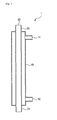
- FIG. 1 is a front view of a heat exchanger.
- the heat exchanger 1 is a double-pipe heat exchanger, in which a first pipe 10 and a second pipe 20, whose diameters are different each other, may be arranged with a concentric axis.
- a second fluid path formed by the second pipe 20 and a first fluid path formed by an external wall of the second pipe 20 and an internal wall of the first pipe 10 may be independent with each other.
- the heat exchanger may receive different temperature fluids introduced into a first fluid inlet 11 formed in the first pipe 10 and a second fluid inlet 21 formed in the second pipe 20, respectively, to perform a heat exchange due to the temperature difference between the two fluids.
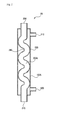
- FIG. 2 is a front view of a heat exchanger according to an embodiment.
- FIG. 3 is a front view of a heat exchanger according to another embodiment.
- the heat exchanger 2A, 2B may include a first pipe 100A, 100B and a second pipe 200A, 200B.
- a first fluid may be introduced into and circulated in the first pipe 100A, 100B, while a second fluid may be introduced into and circulated in the second pipe 200A, 200B, which may be arranged in the first pipe 200A, 200B in the form of a double-pipe type heat exchanger.
- the first fluid may be introduced into the first pipe 100A, 100B through a first fluid inlet 110 formed in one end of the first pipe 100A, 100B, and may be discharged through a first fluid outlet 120 formed in the other end of the first pipe 100.
- the second fluid may be introduced into the second pipe 200A, 200B through a second fluid inlet 210 formed in one end of the second pipe 200A, 200B, and may be discharged through a second fluid outlet 220 formed in the other end of the second pipe 200A, 2008.
- the first and second fluids circulating in the first and second pipes 100A, 100B and 200A, 200B may have different temperatures from each other and a heat exchange may be made utilizing the temperature difference between two fluids. That is, a higher temperature one of the two fluids may be cooled and a lower temperature one of the two fluids heated.
- the first pipe 100A of the heat exchanger 2A may be as a straight pipe of a cylindrical shape
- the second pipe 200A may be formed in a wave shape in which a convex portion 230 and a concave portion 240 may be repeatedly formed.
- the convex portion 230 of the second pipe 200A may contact an internal surface of the first pipe 100A and may be fixed thereto. That is, vibration occurring when the fluid is circulated may be prevented by making the second pipe 200 not a straight type pipe but a wave type pipe, and an external surface of the second pipe 200A may contact the internal surface of the first pipe 100A.
- vibration occurring when the fluid is circulated may be prevented by forming the second pipe 200A in a structure in which the convex portion 230 and concave portion 240 are repeatedly formed, and then making the convex portion 230 contact the internal surface of the first pipe 100A.
- the first pipe 100B may be formed in a wave shape, in which a convex portion 130 and a concave portion 140 may be repeatedly formed and the second pipe 200B formed in a straight shape. That is, the concave portion 140 of the first pipe 100B may contact an external surface of the second pipe 200B, so that vibration occurring when the fluid is circulated may be prevented.
- the first pipe 100B may be formed in a wave shape, and the second pipe 200B formed in a straight line shape so as to contact an internal surface of the first pipe 100B and may be fixed thereto.
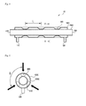
- FIG. 4 is a front view of a heat exchanger in accordance with another embodiment
- FIG. 5 is a sectional side view of the heat exchanger of FIG. 4 , taken along line V-V of FIG. 4 .
- a heat exchanger 2C in accordance with this embodiment may include a first pipe 100C, into which a first fluid may be introduced and flow, a second pipe 200C inserted into the first pipe 100C so as to form concentric circles therewith and into which a second fluid may be introduced and flow, and one or more vibration preventing member(s) 300 installed between the first and second pipes 100C and 200C, so as to prevent vibration occurring when the fluid is circulated.
- the first and second pipes 100C and 200C are each formed as a straight pipe having a cylindrical shape.
- the vibration preventing member(s) 300 may be formed in a hemisphere shape and may be fixed to an internal surface of the first pipe 100C, such that a convex surface thereof may contact an external surface of the second pipe 200C.
- a plurality of vibration preventing members 300 may be provided on the internal surface of the first pipe 100C in a circumferential direction with a predetermined space therebetween along a longitudinal direction of the first pipe 100C.
- three vibration preventing members 300 may be arranged with a space therebetween in the circumferential direction of the first pipe 100 so that three convex projections 310 may contact the external surface of the second pipe 200C.
- a central angle ⁇ formed by two projections 310 of the three projections 300 may range from approximately 100° to approximately 140°.
- a distance L between the vibration preventing members 300 disposed with the space therebetween in the longitudinal direction of the first pipe 100C may be approximately 20 to approximately 40 times an external diameter of the second pipe 200C.
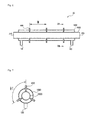
- FIG.6 is a front view of a heat exchanger in accordance with another embodiment
- FIG. 7 is a sectional side view of the heat exchanger of FIG. 6 taken along line VII-VII.
- the heat exchanger 2D in accordance with this embodiment may be similar in construction to the heat exchanger 2C of the previous embodiment, except that the vibration preventing member(s) 400 may be formed in a pin shape.
- the vibration preventing member(s) 400 of the heat exchanger 2D in accordance with this embodiment may be fixed to and through the first pipe 100D with a predetermined space therebetween, and ends of the vibration preventing member(s) 400 may contact an external surface of the second pipe 200D so as to support the second pipe 200D.
- the vibration preventing member(s) 400 may pass through the first pipe 100D and may be fixed to the first pipe 100D using a method, such as, for example, welding, and ends thereof may contact the external surface of the second pipe 200D.
- a plurality of vibration preventing members 400 may be provided with a predetermined space therebetween in a longitudinal direction of the first pipe 100D, and may be disposed on an internal surface of the first pipe 100D in a circumferential direction of the first pipe 100D.
- the vibration preventing members 400 may be pins arranged with a space therebetween in the circumferential direction of the first pipe 100D, so that ends of the pins, which may be formed in a tapered shape, may contact the external surface of the second pipe 200D.
- a central angle ⁇ 1 formed between two pins of the three pins of the vibration preventing members 400 may range from approximately 100° to approximately 140°. Further, a distance M between the vibration preventing members 400 disposed with the space along the longitudinal direction of the first pipe 100D may be approximately 20 to approximately 40 times an external diameter of the second pipe 200D.
- Embodiments disclosed herein provide a heat exchanger capable of preventing a vibration phenomenon of an internal pipe when fluid is circulated therein, by including a vibration preventing structure in a straight-type double pipe heat exchanger.
- Embodiments disclosed herein provide a heat exchanger which may include a first pipe, through which a first fluid may pass, and a second pipe disposed in the first pipe, through which a second fluid may pass, wherein the first and second pipes may touch each other so that the second pipe may be prevented from vibrating.
- first pipe may be formed in a cylindrical shape
- second pipe may be formed in a wave shape, so that a convex portion of the second pipe contacts an internal surface of the first pipe.
- first pipe may be formed in a wave shape
- second pipe may be formed in a cylindrical shape, so that a concave portion of the first pipe contacts an external surface of the second pipe.
- first and second pipes may be formed in a cylindrical shape, and a vibration preventing member may be included between the first and second pipes in order to prevent the second pipe from vibrating.
- the vibration preventing member may be formed in a hemisphere shape and fixed to the internal surface of the first pipe. A convex portion of the vibration preventing member may contact the external surface of the second pipe.
- a plurality of the vibration preventing members may be arranged across a space along a longitudinal direction of the first pipe, and may be radially and circumferentially disposed on the internal surface of the first pipe.
- three vibration preventing members may be circumferentially arranged across a space, and a central angle formed by two of the three vibration preventing members may range from approximately 100° to 140°.
- a distance between the vibration preventing members arranged in the longitudinal direction of the first pipe may be approximately 20 to 40 times an external diameter of the second pipe.
- the vibration preventing member may be formed in a pin shape, so that the member may be fixed through the first pipe and an end of the member may be brought into contact with the external surface of the second pipe.
- any reference in this specification to "one embodiment,” “an embodiment,” “example embodiment,” etc. means that a particular feature, structure, or characteristic described in connection with the embodiment is included in at least one embodiment of the invention.
- the appearances of such phrases in various places in the specification are not necessarily all referring to the same embodiment.
Landscapes
- Engineering & Computer Science (AREA)
- Physics & Mathematics (AREA)
- Thermal Sciences (AREA)
- Mechanical Engineering (AREA)
- General Engineering & Computer Science (AREA)
- Heat-Exchange Devices With Radiators And Conduit Assemblies (AREA)
Applications Claiming Priority (1)
| Application Number | Priority Date | Filing Date | Title |
|---|---|---|---|
| KR1020100002373A KR101608996B1 (ko) | 2010-01-11 | 2010-01-11 | 열 교환기 |
Publications (2)
| Publication Number | Publication Date |
|---|---|
| EP2351978A2 true EP2351978A2 (de) | 2011-08-03 |
| EP2351978A3 EP2351978A3 (de) | 2012-10-31 |
Family
ID=43858793
Family Applications (1)
| Application Number | Title | Priority Date | Filing Date |
|---|---|---|---|
| EP11150196A Withdrawn EP2351978A3 (de) | 2010-01-11 | 2011-01-05 | Doppelrohr-Wärmetauscher mit Vibrationsminderung |
Country Status (4)
| Country | Link |
|---|---|
| US (1) | US20110168369A1 (de) |
| EP (1) | EP2351978A3 (de) |
| KR (1) | KR101608996B1 (de) |
| CN (1) | CN102121800B (de) |
Families Citing this family (26)
| Publication number | Priority date | Publication date | Assignee | Title |
|---|---|---|---|---|
| KR101600296B1 (ko) * | 2010-08-18 | 2016-03-07 | 한온시스템 주식회사 | 이중관식 열교환기 및 그 제조방법 |
| CN102406146A (zh) * | 2011-11-10 | 2012-04-11 | 厦门市柏绿食品有限公司 | 一种蚝汁加工后的快速冷却装置和方法 |
| CN102778150B (zh) * | 2012-07-18 | 2016-03-02 | 梅州市志浩电子科技有限公司 | 化学沉积温控系统及其温度调节方法 |
| US9568249B2 (en) * | 2012-08-28 | 2017-02-14 | Denso International America, Inc. | Heat exchanger |
| US20140083660A1 (en) * | 2012-09-25 | 2014-03-27 | John McDermott | Heat recovery system |
| JP6099408B2 (ja) * | 2013-01-18 | 2017-03-22 | 三菱日立パワーシステムズ株式会社 | 発電システム、及び発電システムの運転方法 |
| US9752835B2 (en) | 2013-06-06 | 2017-09-05 | Honeywell International Inc. | Unitary heat exchangers having integrally-formed compliant heat exchanger tubes and heat exchange systems including the same |
| US9764435B2 (en) * | 2013-10-28 | 2017-09-19 | Honeywell International Inc. | Counter-flow heat exchange systems |
| US20150140190A1 (en) * | 2013-11-19 | 2015-05-21 | Nestec Sa | Concentric symmetrical branched heat exchanger system |
| US20150168074A1 (en) * | 2013-12-12 | 2015-06-18 | Penn Aluminum International LLC | Concentric Tube Heat Exchanger and Method |
| FR3023907B1 (fr) * | 2014-07-16 | 2016-08-19 | Valeo Systemes Thermiques | Bouteille de condenseur adaptee pour une utilisation dans un circuit de climatisation, plus particulierement le circuit de climatisation d'un vehicule automobile |
| GB201513415D0 (en) * | 2015-07-30 | 2015-09-16 | Senior Uk Ltd | Finned coaxial cooler |
| EP3306248B1 (de) * | 2016-10-05 | 2019-03-06 | Hs R & A Co., Ltd. | Doppelrohrwärmetauscher und verfahren zur herstellung davon |
| CN107673360A (zh) * | 2017-11-13 | 2018-02-09 | 浙江工业大学上虞研究院有限公司 | 用于制备三氯氢硅的化工设备 |
| CN107720758A (zh) * | 2017-11-13 | 2018-02-23 | 浙江工业大学上虞研究院有限公司 | 化工用生产系统 |
| CN108267031B (zh) * | 2018-01-25 | 2023-10-13 | 浙江旺能环保有限公司 | 利用连排或疏水废弃热能提高锅炉进风温度的换热装置 |
| IT201800004827A1 (it) * | 2018-04-24 | 2019-10-24 | Scambiatore di calore a doppio tubo e relativo metodo di fabbricazione | |
| JP7169923B2 (ja) * | 2019-03-27 | 2022-11-11 | 日本碍子株式会社 | 熱交換器 |
| CN111750705B (zh) * | 2019-03-28 | 2022-04-29 | 日本碍子株式会社 | 热交换器的流路结构以及热交换器 |
| DE202019102689U1 (de) * | 2019-05-13 | 2019-06-17 | Konvekta Aktiengesellschaft | Wärmetauscher und Kreislaufsystem zum Temperieren |
| CN114174660B (zh) | 2019-05-21 | 2024-10-11 | 通用电气公司 | 能量转换设备和系统 |
| US11703283B2 (en) | 2020-01-24 | 2023-07-18 | Hamilton Sundstrand Corporation | Radial configuration for heat exchanger core |
| US11453160B2 (en) | 2020-01-24 | 2022-09-27 | Hamilton Sundstrand Corporation | Method of building a heat exchanger |
| US11460252B2 (en) | 2020-01-24 | 2022-10-04 | Hamilton Sundstrand Corporation | Header arrangement for additively manufactured heat exchanger |
| US11441850B2 (en) * | 2020-01-24 | 2022-09-13 | Hamilton Sundstrand Corporation | Integral mounting arm for heat exchanger |
| CN112413764A (zh) * | 2020-12-03 | 2021-02-26 | 合肥上华工程设计有限公司 | 中央真空热交换工艺与装置 |
Family Cites Families (19)
| Publication number | Priority date | Publication date | Assignee | Title |
|---|---|---|---|---|
| FR362995A (fr) * | 1906-02-05 | 1906-07-18 | Paul Determes | Tubes doubles à ailettes pour le chauffage ou le refroidissement des liquides |
| GB725075A (en) * | 1952-07-09 | 1955-03-02 | Mannesmann Ag | Improvements in or relating to tubes for heat exchangers |
| DE917009C (de) * | 1952-07-10 | 1954-08-23 | Mannesmann Ag | Doppelrohr |
| JPS51142660A (en) * | 1975-06-03 | 1976-12-08 | Matsushita Electric Industrial Co Ltd | Method of mounting resisting element* slider and terminal in variable* resistor |
| JPS52124346U (de) * | 1976-03-19 | 1977-09-21 | ||
| FR2497937B1 (fr) * | 1981-01-13 | 1986-03-07 | Stein Industrie | Dispositif d'echange de chaleur a faisceau de tubes avec lyres de dilatation soustraites aux vibrations |
| JPS5893677U (ja) * | 1981-12-17 | 1983-06-24 | カルソニックカンセイ株式会社 | ラジエ−タ内蔵式二重管形オイルク−ラ |
| FR2540984A1 (fr) * | 1983-02-11 | 1984-08-17 | Trepaud Pierre | Appareil echangeur de chaleur, notamment generateur de vapeur |
| FR2608264B3 (fr) * | 1986-12-09 | 1989-03-17 | Bracon Daniel | Echangeur coaxial monotubulaire |
| DE19624030A1 (de) * | 1996-06-17 | 1997-12-18 | Kme Schmoele Gmbh | Verfahren zur Herstellung eines gewendelten Koaxialrohrs für einen Wärmetauscher und Wärmetauscher, der ein gewendeltes Koaxialrohr aufweist |
| JP3811123B2 (ja) * | 2002-12-10 | 2006-08-16 | 松下電器産業株式会社 | 二重管式熱交換器 |
| JP4494049B2 (ja) * | 2004-03-17 | 2010-06-30 | 株式会社ティラド | 二重管型熱交換器の製造方法および、該方法による二重管型熱交換器 |
| CN100460794C (zh) * | 2004-11-09 | 2009-02-11 | 株式会社电装 | 双壁管及其制造方法和设有双壁管的制冷剂循环装置 |
| WO2006077657A1 (ja) * | 2005-01-21 | 2006-07-27 | T.Rad Co., Ltd. | 二重管型熱交換器およびその製造方法 |
| CA2499865C (en) * | 2005-03-24 | 2012-06-12 | Milan Rybak | Improved recuperator of flue gas heat |
| DE202007010274U1 (de) * | 2007-07-24 | 2007-09-27 | BSH Bosch und Siemens Hausgeräte GmbH | Wärmetauscher und Kältegerät |
| JP5003968B2 (ja) * | 2008-03-06 | 2012-08-22 | 日立電線株式会社 | 過冷却器用伝熱管及びその製造方法 |
| JP2009270802A (ja) * | 2008-04-08 | 2009-11-19 | Tgk Co Ltd | 内部熱交換器 |
| JP2012007767A (ja) | 2010-06-23 | 2012-01-12 | Sumitomo Light Metal Ind Ltd | 熱交換器用二重管 |
-
2010
- 2010-01-11 KR KR1020100002373A patent/KR101608996B1/ko not_active Expired - Fee Related
-
2011
- 2011-01-05 EP EP11150196A patent/EP2351978A3/de not_active Withdrawn
- 2011-01-10 US US12/987,473 patent/US20110168369A1/en not_active Abandoned
- 2011-01-11 CN CN201110009952.6A patent/CN102121800B/zh not_active Expired - Fee Related
Non-Patent Citations (1)
| Title |
|---|
| None |
Also Published As
| Publication number | Publication date |
|---|---|
| CN102121800B (zh) | 2014-03-12 |
| US20110168369A1 (en) | 2011-07-14 |
| KR101608996B1 (ko) | 2016-04-05 |
| KR20110082411A (ko) | 2011-07-19 |
| CN102121800A (zh) | 2011-07-13 |
| EP2351978A3 (de) | 2012-10-31 |
Similar Documents
| Publication | Publication Date | Title |
|---|---|---|
| US20110168369A1 (en) | Heat exchanger | |
| EP2351979B1 (de) | Wärmetauscher mit drei konzentrischen Rohren | |
| US6920917B2 (en) | Double-pipe heat exchanger | |
| JP6032585B2 (ja) | 三重管の構造及び熱交換器 | |
| US20200333089A1 (en) | A heat exchanger and an additive manufacturing method for manufacturing a heat exchanger | |
| JP2009216309A (ja) | 熱交換器 | |
| US11982499B2 (en) | Heat exchanger with heat transfer augmentation features | |
| EP3581868A1 (de) | Wasserwärmetauscher und gaskühler | |
| JP5157617B2 (ja) | 熱交換器 | |
| JP2009264644A (ja) | 熱交換器 | |
| US20110203782A1 (en) | Heat exchanger fins, assemblies and methods | |
| JP6211313B2 (ja) | 3重管式熱交換器 | |
| JP2010038429A (ja) | 熱交換器 | |
| KR102010156B1 (ko) | 쉘앤플레이트 열교환기용 쉘 및 이를 구비한 쉘앤플레이트 열교환기 | |
| JP2010255856A (ja) | 熱交換器およびそれを用いたヒートポンプ給湯機 | |
| WO2024203334A1 (ja) | 熱交換用二重管 | |
| JP2008267631A (ja) | 熱交換器 | |
| JP5533328B2 (ja) | 熱交換器 | |
| CN212902032U (zh) | 一种换热件及加热器具 | |
| JP2010210137A (ja) | 熱交換器 | |
| EP3027996B1 (de) | Rohr für einen verbrennungswärmetauscher | |
| JP2012007771A (ja) | 熱交換器 | |
| JP2010255857A (ja) | 熱交換器およびそれを用いたヒートポンプ給湯機 | |
| CN114198910A (zh) | 一种换热件及加热器具 | |
| KR100565505B1 (ko) | 공기조화기의 열교환기 |
Legal Events
| Date | Code | Title | Description |
|---|---|---|---|
| PUAI | Public reference made under article 153(3) epc to a published international application that has entered the european phase |
Free format text: ORIGINAL CODE: 0009012 |
|
| 17P | Request for examination filed |
Effective date: 20110201 |
|
| AK | Designated contracting states |
Kind code of ref document: A2 Designated state(s): AL AT BE BG CH CY CZ DE DK EE ES FI FR GB GR HR HU IE IS IT LI LT LU LV MC MK MT NL NO PL PT RO RS SE SI SK SM TR |
|
| AX | Request for extension of the european patent |
Extension state: BA ME |
|
| PUAL | Search report despatched |
Free format text: ORIGINAL CODE: 0009013 |
|
| AK | Designated contracting states |
Kind code of ref document: A3 Designated state(s): AL AT BE BG CH CY CZ DE DK EE ES FI FR GB GR HR HU IE IS IT LI LT LU LV MC MK MT NL NO PL PT RO RS SE SI SK SM TR |
|
| AX | Request for extension of the european patent |
Extension state: BA ME |
|
| RIC1 | Information provided on ipc code assigned before grant |
Ipc: F28D 7/10 20060101AFI20120921BHEP |
|
| STAA | Information on the status of an ep patent application or granted ep patent |
Free format text: STATUS: THE APPLICATION IS DEEMED TO BE WITHDRAWN |
|
| 18D | Application deemed to be withdrawn |
Effective date: 20140801 |