EP2350552B1 - Procédé et dispositif de stabilisation d'une direction de visée pour des armes à feu et arme à feu - Google Patents
Procédé et dispositif de stabilisation d'une direction de visée pour des armes à feu et arme à feu Download PDFInfo
- Publication number
- EP2350552B1 EP2350552B1 EP09825064.0A EP09825064A EP2350552B1 EP 2350552 B1 EP2350552 B1 EP 2350552B1 EP 09825064 A EP09825064 A EP 09825064A EP 2350552 B1 EP2350552 B1 EP 2350552B1
- Authority
- EP
- European Patent Office
- Prior art keywords
- barrel
- butt end
- weapon
- control system
- orientation
- Prior art date
- Legal status (The legal status is an assumption and is not a legal conclusion. Google has not performed a legal analysis and makes no representation as to the accuracy of the status listed.)
- Active
Links
Images


Classifications
-
- F—MECHANICAL ENGINEERING; LIGHTING; HEATING; WEAPONS; BLASTING
- F41—WEAPONS
- F41A—FUNCTIONAL FEATURES OR DETAILS COMMON TO BOTH SMALLARMS AND ORDNANCE, e.g. CANNONS; MOUNTINGS FOR SMALLARMS OR ORDNANCE
- F41A27/00—Gun mountings permitting traversing or elevating movement, e.g. gun carriages
- F41A27/30—Stabilisation or compensation systems, e.g. compensating for barrel weight or wind force on the barrel
-
- F—MECHANICAL ENGINEERING; LIGHTING; HEATING; WEAPONS; BLASTING
- F41—WEAPONS
- F41C—SMALLARMS, e.g. PISTOLS, RIFLES; ACCESSORIES THEREFOR
- F41C23/00—Butts; Butt plates; Stocks
- F41C23/12—Auxiliary stocks for stabilising, or for transforming pistols, e.g. revolvers, into shoulder-fired guns
-
- F—MECHANICAL ENGINEERING; LIGHTING; HEATING; WEAPONS; BLASTING
- F41—WEAPONS
- F41C—SMALLARMS, e.g. PISTOLS, RIFLES; ACCESSORIES THEREFOR
- F41C23/00—Butts; Butt plates; Stocks
- F41C23/20—Butts; Butt plates; Mountings therefor
-
- F—MECHANICAL ENGINEERING; LIGHTING; HEATING; WEAPONS; BLASTING
- F41—WEAPONS
- F41C—SMALLARMS, e.g. PISTOLS, RIFLES; ACCESSORIES THEREFOR
- F41C27/00—Accessories; Details or attachments not otherwise provided for
- F41C27/22—Balancing or stabilising arrangements on the gun itself, e.g. balancing weights
-
- F—MECHANICAL ENGINEERING; LIGHTING; HEATING; WEAPONS; BLASTING
- F41—WEAPONS
- F41G—WEAPON SIGHTS; AIMING
- F41G1/00—Sighting devices
- F41G1/46—Sighting devices for particular applications
-
- F—MECHANICAL ENGINEERING; LIGHTING; HEATING; WEAPONS; BLASTING
- F41—WEAPONS
- F41G—WEAPON SIGHTS; AIMING
- F41G3/00—Aiming or laying means
- F41G3/12—Aiming or laying means with means for compensating for muzzle velocity or powder temperature with means for compensating for gun vibrations
Definitions
- the present invention relates to a method according to the introductory portion of the attached claim 1.
- the invention also relates to a device according to the introductory portion of the attached claim 3.
- the present invention further relates to a firearm according to claim 15.
- the accuracy of fire in rifle shooting and in handgun shooting is limited inter alia of the quality of the weapon and ammunition and of the kind of the sights used.
- One reason for the point of impact to vary from shot to shot may eg be that the bullet weight and gun-powder load varies from cartridge to cartridge.
- the point of impact of the shots will get a certain spread which is caused by the quality of the materials used.
- the spread caused by shortcomings of the weapon precision or the quality of the ammunition by free hand shooting, i.e.
- the present invention may be applied to weapons with a relatively long barrel without impairing the so called balance, or, in other words, that the point of gravity is moved forward.
- a major part of the elements comprised by the servo system i.e. motors, electronics and mechanics, are located at the weapon rear end, so that the weapon point of gravity is not moved forward by the additional elements.
- a drawback with the design according to the Patent 5 834 677 is that the sight, to be able to show the actual direction of shot, must be mounted on the barrel surrounded by the pipe. This complicates the design.
- the mounting of the sight according to the present patent is done in the same way as on conventional weapons. Therefore, according to the present invention the design becomes less complicated.
- WO00/79207 forms the starting point for claims 1 and 3 and discloses a further system in which optics and an image detection device are used to guide a rifle.
- optics and an image detection device are used to guide a rifle.
- such system requires optimal light conditions.
- An object of the present invention is, inter alia, to solve the problems associated with the prior art technique.
- the present invention regards a method and a device designed in such a way that movements of the barrel at aiming are attenuated by means of a servo system stabilizing the orientation of the barrel built-in in the weapon.
- the servo system measuring means are included continuously measuring the rotation speed vertically and horizontally of the barrel and motors able to change the direction of the barrel in relation to the butt end so that the orientation of the barrel is stabilized whereby the aiming of the weapon in the desired direction is simplified and the accuracy of fire increases.
- the stabilization By means of the stabilization the unintentional barrel movements, appearing at the aiming when the marksman, without having any physical support for the weapon, tries to control the sight direction towards the target, are counteracted.
- the technique may be applied for all kinds of rifles and also for handguns, like pistols and revolvers.
- the invention comprises a rifle or a small arm designed in such a way that the shot at aiming is supported by a stabilizing servo system which attenuates the fast and unintentional barrel movements, whereby the marksman more easily can control the aiming direction towards a desired hit position and, by the calmer movement of the barrel and aiming direction also get a longer time to choose the right firing moment.
- the weapon is divided into two mutually movable parts, a front part, in which the barrel is included, and the butt end.
- the two parts are movable in relation to each other in a common point where they are connected by a biaxial bearing a hinge, which provides movability horizontally and vertically.
- the bearing is placed where the butt end adjoins the front part.
- the angle between the orientation of the butt end and the barrel is regulated by a servo system controlling the angle between the butt end and the barrel so that fast changes in the barrel orientation are counteracted and attenuated, which makes it easier to aim and to fire a shot in a desired direction.
- the turning torque changing the barrel orientation is accomplished by applying a turning torque in the opposite direction by the servo system. If eg the barrel shall be turned clockwise in order to compensate an externally, i.e. by the marksman, imposed movement, the butt end is turned anticlockwise. The moment of inertia of the butt end causes a turning torque to act on the barrel the direction of which is then changed. If the butt end at the rear end rests against a more or less solid object, in rifle shooting normally the shoulder of the marksman, the turning torque increases.
- the conditions are principally similar but the shorter butt end and the fact that the weapon does not have contact with any big mass at the rear end, as is the case in rifle shooting (the shoulder of the marksman), means that the moment of inertia of the butt end becomes of greater importance.
- the mass of the butt end may be arranged so that the heavier objects are placed farther away from and behind the bearing in order to give the butt end a moment of inertia great enough.
- the stabilizing servo system acts so that the movement of the barrel upwards, which arises at the recoil after a shot is also attenuated, so that one, with a weapon designed according the present patent and especially a semiautomatic rifle, is able to fire a well directed second shot faster.
- the method may further comprise any of the following steps:
- the joint is arranged as a cardan joint configuration.
- the high pass filter is arranged with a limiting frequency in the interval about 0,5 to about 5 Hz.
- the operation element is arranged to be connected to said operation means to mutually turn said front part and said rear part.
- the operation element are applied to a portion, turned from the front part, of an operation means in the form of a rod element protruding into the butt end.
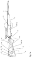
- Fig 1a The figure shows a rifle with a stabilized aiming direction seen from the right side. Certain important functional elements, which are hidden, are shown in broken lines. Certain hidden elements are not shown in the drawing. Between the two mutually movable parts, front part 1 and the butt end 2, parts of a hinge 3, a bearing 3, which gives the two parts movability horizontally and vertically may be seen. The gap between the butt end and the front part have for clarity reasons been made bigger than what is needed to give the desired movability. Through the bearing 3 the rod 10 applied in the front part protrudes backwards in the butt end.
- the arm 8v is coupled so that it can transmit a rotational movement of the motor 6v to a mainly linear and vertical movement of the rod 10 end, whereby the angle between the butt end and the barrel can be changed. Parts which give movement horizontally have been deleted in the figure to increase the clarity. In the rear end of the butt end the protruding press plate 12 may be seen.
- Fig. 1b The figure shows a rifle with stabilized aiming direction seen from above. From the hidden elements only the rod 10 and the motors 6h and 6v have been included.
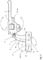
- FIG. 2 The figure shows a revolver with stabilized aiming direction seen from the right-hand side.
- batteries, electronics, motors and other elements have been located to an apparatus box fixed under the pistol-grip.
- moment of inertia of the butt end heavy elements have been located far from and behind the bearing 3.
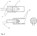
- Fig. 3a The figure shows the principle of how the mechanics connecting the motors 6h and 6v with the rod 10 may be arranged.
- the motors are used with a rotating wheel on the output shaft.
- Fig. 3b The figure shows the principle for how the mechanics connecting the motors 6h and 6v with the rod 10 may be arranged when motors with a linear movement are used.
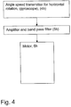
- Fig.4 In the figure it is diagrammatically shown how the electronic components and the motors in the horizontal channel are coupled. The components in the vertical channel are coupled in an analogous way.
- FIG. 5 The figure shows the bearing between the barrel and the butt end and the rod 10.
- the flanges to the right 16 are used to fasten the bearing in the barrel 1 eg with a bolted joint.
- the flanges to the left 17 are used to fasten the bearing in the butt end in a corresponding way.
- the weapon is divided into two mutually movable parts, a front part 1 including the barrel and the butt end 2.
- the two parts 1 and 2 are movable in relation to each other in a common point whereat they are connected by a biaxial bearing 3 suitably designed as a cardan joint.
- the bearing is located where the butt end connects to the front part. The bearing makes it possible to rotate the butt end around the bearing point in relation to the barrel in two mutually perpendicular planes, vertically and horizontally.
- the angle between the orientation of the butt end and the barrel is regulated by a control system, preferably a servo system controlling the angle between the butt end and the barrel so that fast changes in the barrel orientation are attenuated, which makes it easier to aim and to fire shots in a desired direction.
- a control system preferably a servo system controlling the angle between the butt end and the barrel so that fast changes in the barrel orientation are attenuated, which makes it easier to aim and to fire shots in a desired direction.
- control system the servo system, there are according to a preferred embodiment included:
- the two motors 6h and 6v are via arms 8h and 8v coupled to the rear end of the rod running through the center in the cardan joint 3 and is fixed to the weapon front part 1 where it, suitably, is fastened in the part of the cardan joint being fastened in the weapon front part 1 according to figure 5 , i.e. the right hand part with flanges directed to the right 16.
- the rear end of the rod is moved by the arms 8h and 8v, respectively, the angle between the barrel 1' and the butt end 2' is changed by the butt end and the barrel rotating in relation to each other in the bearing 3.
- the motors 6h,6v thus constitute drive means for the control system affection of the angle between the two parts 1, 2.
- other drive means than electrical motors may be imagined, eg electromagnetic devices or piezoelectric devices.
- the function of the servo system is to, by changes in the barrel longitudinal direction orientation, change the angle in the bearing point 3 so that the change in the barrel direction is counteracted.
- the principal function of a rifle designed according to the invention may be described by the following example.
- the marksman after having activated the main current switch 14 and in this way started the servo system electronics, makes an aiming, i.e. lifts the weapon and approaches the butt end to the shoulder.
- the current switch 15 is activated, which makes the servo system motors to be activated, whereby the barrel sighting from then on is stabilized.
- the marksman aims at a target he wants to shoot and that he during the aiming unintentionally lowers the hand holding around the front stock, i.e. the bottom part of the weapon front part 1.
- a rotation in the rifle starts, i.e. the barrel and the butt end 1, 2 rotate together around the point where the butt end is in contact with shoulder of the shot.
- the rotation if we consider the rifle of fig. 1a , to be directed clockwise.
- the rotation gives rise to a change in the signal from the gyroscope 4v measuring the barrel vertical rotational speed.
- the signal affects, via the amplifier 5v, the motor 6v changing the angle vertically between the butt end 2 and barrel 1 so that the rear end of the rod 10 is pressed downwards in relation to the butt end rear end, whereby the butt end front and the barrel rear end are affected by a force directed downwards. Since the force pressing the rod 10 downwards is not directed towards the front part center of gravity but towards a point behind the center of gravity (to the left in figure 1a ), this force gives rise to a turning torque acting on the barrel 1, which torque in figure 1a will have the direction anticlockwise. The barrel rear end is lowered whereby its orientation is changed so that the aiming direction is raised, whereby the unintentional lowering of the aiming direction is decreased or eliminated. In this way the aiming direction (and the shot direction) is returned to a greater or smaller extent, depending on the movement speed and size to the orientation the barrel had before it was lowered by the marksman.
- the function gets principally the same with the exception that the butt end 2 rear end does not lie against the shoulder of the marksman and thereby is not fixed to a (relatively) fixed point. Instead of the butt end 2 rotating around the butt end rear end, it tends to rotate around its mass center, i.e. its center of gravity. If the weight of the part here called the butt end 2 and including the servo system electronics and mechanic is great enough and is located far enough from the bearing 3, the turning torque on the barrel when the servo system operates will be great enough for the barrel to be stabilized by the mass and the moment of inertia of the butt end 2.
- the signal from the angle speed transmitters is intended to be filtered by a high pass filter in the band pass filters of the amplifiers and then suppress signals having comparatively low frequency and let signals having comparatively high frequency through, so that comparatively slow changes of the barrel orientation are not counteracted, attenuated, to as high a degree as fast, usually unintentional, changes of orientation.
- high pass filtering with a chosen limiting frequency of the high pass filter for adaption of attenuation of barrel movements to eg the actual weapon and use.
- a preferred interval for such limiting frequencies is about 0,5 to about 5 Hz.
- the servo system electronics and motors are driven by batteries which are built-in in the weapon 13.
- a press plate 12 is included in a rifle and a switch 15 connected to the plate and mounted in the butt end end, which switch activates the servo system motors.
- the press plate is pushed out to its outer position by a spring and is pushed in when the marksman puts the butt end against the shoulder.
- the switch 15 is switched off.
- a prerequisite for the servo system motors to operate is that the main switch 14 is switched on and that the press plate 12 is pushed in and thereby the switch 15 is switched on.
- the press plate 12 and the switch 15 connected thereto thus have as their function to activate the servo system motors and stabilize the aiming direction only during aiming, i.e. when the rifle is held pressed against the shoulder, not else. In this way the consumption of current is decreased.
Landscapes
- Engineering & Computer Science (AREA)
- General Engineering & Computer Science (AREA)
- Physics & Mathematics (AREA)
- Optics & Photonics (AREA)
- Aiming, Guidance, Guns With A Light Source, Armor, Camouflage, And Targets (AREA)
- Control Of Position Or Direction (AREA)
Claims (13)
- Procédé de stabilisation des mouvements de canon d'une arme, par exemple, un fusil ou un petit pistolet, lors de la visée par atténuation de l'influence, principalement, de mouvements de canon involontaires sur l'orientation du canon, comprenant les étapes consistant à- fournir une articulation (3) entre la partie avant d'arme (1), qui comprend le canon (1') et une détente
et la partie arrière d'arme (2), qui comprend l'extrémité crosse d'arme (2'), pour une mobilité mutuelle entre lesdites parties ;- détecter en continu le mouvement en direction longitudinale du canon dans au moins deux plans ;- commander au moins un angle entre l'extrémité crosse et l'orientation en direction longitudinale du canon, respectivement au moyen d'un système de commande (4h, 4v, 5h, 5v, 6h, 6v) de sorte que des changements dans l'orientation du canon sont contrés ;- fournir deux canaux du système de commande, un canal par plan et, ici, de préférence un canal vertical et un horizontal, chacun comprenant un moyen (4h, 4v) pour la détection de la vitesse angulaire, des émetteurs de vitesse angulaire, faisant référence au mouvement dans la direction longitudinale du canon dans le plan respectif ; et- fournir ledit système de commande comme un système d'asservissement pour commander l'angle entre l'extrémité crosse et l'orientation dans la direction longitudinale du canon, respectivement, dans deux plans mutuellement perpendiculaires. - Procédé selon la revendication 1, caractérisé en l'étape consistant à- tourner mutuellement ladite partie avant (1) et ladite partie arrière (2) au moyen d'un moyen d'opération (10) s'étendant depuis ladite articulation et étant agencé au niveau de ladite partie avant et faisant saillie dans l'extrémité crosse de ladite partie arrière pour être affecté par ledit système de commande.
- Dispositif de stabilisation des mouvements de canon d'une arme, par exemple, un fusil ou une arme de poing, lors de la visée par atténuation de l'influence, principalement, de mouvements de canon involontaires sur l'orientation du canon, comprenant- une articulation (3) entre la partie avant d'arme (1), qui comprend le canon (1') et une détente
et l'arrière d'arme (2), qui comprend l'extrémité crosse d'arme (2'), pour une mobilité mutuelle entre lesdites parties ;- des dispositifs (4h, 4v) pour détecter en continu le mouvement en direction longitudinale du canon dans au moins deux plans ;- un système de commande (4h, 4v, 5h, 5v, 6h, 6v) pour commander au moins un angle entre l'extrémité crosse et l'orientation dans la direction longitudinale du canon, respectivement, de sorte que des changements dans l'orientation du canon sont contrés ;- deux canaux du système de commande, un canal par plan et, ici, de préférence un canal vertical et un canal horizontal, chacun comprend un moyen (4h, 4v) pour la détection de la vitesse angulaire, des émetteurs de vitesse angulaire, faisant référence au mouvement du canon dans le plan respectif ; et- ledit système de commande est un système d'asservissement pour commander l'angle entre l'extrémité crosse et l'orientation dans la direction longitudinale du canon, respectivement, dans deux plans mutuellement perpendiculaires. - Dispositif selon la revendication 3, caractérisé par des dispositifs de détection du mouvement dans la direction longitudinale du canon dans deux plans mutuellement perpendiculaires, de préférence un sensiblement vertical et un sensiblement horizontal.
- Dispositif selon l'une quelconque des revendications 3 ou 4, caractérisé en ce que chacun des deux canaux du système de commande comprend un amplificateur (5h, 5v) avec un filtre passe-bande, qui amplifie et filtre le signal provenant de l'émetteur de vitesse angulaire dans le canal,
dans lequel le signal provenant des émetteurs de vitesse angulaire est agencé pour être filtré dans les amplificateurs par un filtre passe-haut et supprime ainsi des signaux ayant une fréquence comparativement basse et laisse passer les signaux ayant une fréquence comparativement élevée, de sorte que des changements comparativement lents de l'orientation du canon ne sont pas contrés, atténués, dans une mesure aussi importante que des changements d'orientation rapides, habituellement involontaires. - Dispositif selon la revendication 5, caractérisé en ce que le filtre passe-haut est agencé avec une fréquence de limitation pour adaptation de l'atténuation des mouvements de canon à, par exemple, une utilisation et une arme réelles.
- Dispositif selon l'une quelconque des revendications 3 à 6, caractérisé en ce qu'un moyen d'opération est prévu pour tourner mutuellement ladite partie avant (1) et ladite partie arrière (2), ledit moyen d'opération (10) s'étendant depuis ladite articulation et étant agencé au niveau de ladite partie avant et faisant saillie dans l'extrémité crosse de ladite partie arrière pour être affecté par ledit système de commande.
- Dispositif selon la revendication 7, caractérisé par un moyen d'entraînement (6h, 6v) dans l'extrémité crosse pour influencer ledit moyen d'opération.
- Dispositif selon la revendication 8, caractérisé par un moyen d'entraînement sous la forme d'un moteur électrique (6h, 6v) par canal du système de commande pour commander l'angle entre l'extrémité crosse et le canon dans la direction verticale et horizontale, respectivement.
- Dispositif selon la revendication 9, caractérisé en ce que les moteurs sont agencés pour affecter un élément d'opération (8h, 8v) pour réaliser chacun un mouvement alternatif principalement linéaire.
- Dispositif selon la revendication 10, caractérisé en ce que les deux moteurs et lesdits éléments d'opération sont agencés pour déplacer les éléments d'opération respectifs dans deux directions mutuellement perpendiculaires correspondant aux deux canaux.
- Dispositif selon l'une quelconque des revendications 3 à 11, caractérisé en ce que le système de commande est agencé pour être activé au moyen de dispositifs commutateurs (7, 12, 15) agencés pour être opérés par une personne effectuant la visée en association avec la visée, de préférence après qu'un commutateur principal (14) pour l'alimentation en courant du système de commande a été placé en position en service.
- Arme à feu, de préférence un fusil ou une petite arme, comprenant une extrémité crosse et un canon caractérisée en ce qu'elle comprend un dispositif selon l'une quelconque des revendications 3 à 12.
Applications Claiming Priority (2)
| Application Number | Priority Date | Filing Date | Title |
|---|---|---|---|
| SE0802342A SE533248C2 (sv) | 2008-11-04 | 2008-11-04 | Metod att gyrostabilisera siktriktningen på gevär och enhandsvapen |
| PCT/SE2009/051249 WO2010053436A1 (fr) | 2008-11-04 | 2009-11-04 | Procédé et dispositif de stabilisation d’une direction de visée pour des armes à feu et arme à feu |
Publications (3)
| Publication Number | Publication Date |
|---|---|
| EP2350552A1 EP2350552A1 (fr) | 2011-08-03 |
| EP2350552A4 EP2350552A4 (fr) | 2014-01-15 |
| EP2350552B1 true EP2350552B1 (fr) | 2016-09-28 |
Family
ID=42153092
Family Applications (1)
| Application Number | Title | Priority Date | Filing Date |
|---|---|---|---|
| EP09825064.0A Active EP2350552B1 (fr) | 2008-11-04 | 2009-11-04 | Procédé et dispositif de stabilisation d'une direction de visée pour des armes à feu et arme à feu |
Country Status (8)
| Country | Link |
|---|---|
| US (1) | US8601736B2 (fr) |
| EP (1) | EP2350552B1 (fr) |
| JP (1) | JP5538412B2 (fr) |
| KR (1) | KR101661718B1 (fr) |
| CN (1) | CN102203542B (fr) |
| RU (1) | RU2524492C2 (fr) |
| SE (1) | SE533248C2 (fr) |
| WO (1) | WO2010053436A1 (fr) |
Families Citing this family (26)
| Publication number | Priority date | Publication date | Assignee | Title |
|---|---|---|---|---|
| US8635798B2 (en) | 2011-08-23 | 2014-01-28 | Tyco Electronics Corporation | Communication connector system for a weapon |
| US9146068B2 (en) * | 2012-01-11 | 2015-09-29 | Dale Albert Hodgson | Motorized weapon gyroscopic stabilizer |
| US9354013B2 (en) | 2012-01-11 | 2016-05-31 | Dale Albert Hodgson | Motorized weapon gyroscopic stabilizer |
| US10203179B2 (en) | 2012-01-11 | 2019-02-12 | Dale Albert Hodgson | Motorized weapon gyroscopic stabilizer |
| US8721355B2 (en) * | 2012-02-01 | 2014-05-13 | Tyco Electronics Corporation | Electrical connector with hood |
| RU2485429C1 (ru) * | 2012-03-13 | 2013-06-20 | Виталий Витальевич Бояркин | Автоматическое оружие с комбинированной схемой применения (варианты) |
| US8863427B2 (en) * | 2012-11-21 | 2014-10-21 | Grip Plus Inc | Automatically adjustable comb for a firearm |
| KR101299187B1 (ko) * | 2013-03-19 | 2013-08-27 | 박상원 | 비동축형 견착부와 조준기를 갖는 굴절형 화기 |
| US9612088B2 (en) | 2014-05-06 | 2017-04-04 | Raytheon Company | Shooting system with aim assist |
| US10408571B2 (en) * | 2015-02-05 | 2019-09-10 | Raytheon Canada Limited | Switch assembly for optical sight activation |
| US9784529B1 (en) * | 2015-04-07 | 2017-10-10 | Matthew G. Angle | Small arms stabilization system |
| USD804602S1 (en) | 2016-01-12 | 2017-12-05 | Magpul Industries Corp. | Firearm stock |
| WO2018005977A1 (fr) | 2016-07-01 | 2018-01-04 | Vista Outdoor Operations Llc | Monture pliante bidirectionnelle à longueur réglable destinée à une arme à feu |
| USD828476S1 (en) | 2016-12-08 | 2018-09-11 | Vista Outdoor Operations Llc | Firearm stock |
| GB201700648D0 (en) * | 2017-01-13 | 2017-03-01 | Marksmanship Tech Ltd | System and method for correcting aim by motion analysis for small arms weapons |
| USD844735S1 (en) | 2017-03-07 | 2019-04-02 | Magpul Industries Corp. | Firearm stock |
| US10345076B2 (en) | 2017-03-07 | 2019-07-09 | Magpul Industries Corp. | Firearm barrel tray, stock, and related methods |
| CN111213027B (zh) * | 2017-08-15 | 2023-08-04 | 帕斯帕制药有限公司 | 枪支稳定装置 |
| RU2683966C1 (ru) * | 2017-10-17 | 2019-04-03 | Николай Андреевич Гаврилов | Способ наведения и устройство, предполагающее его реализацию |
| EP3704437A4 (fr) * | 2017-11-03 | 2021-07-28 | Aimlock Inc. | Systèmes d'armes motorisés semi-autonomes |
| WO2021080683A1 (fr) | 2019-10-25 | 2021-04-29 | Aimlock Inc. | Détente et dispositif d'actionnement de sécurité et procédé associé |
| US11274904B2 (en) | 2019-10-25 | 2022-03-15 | Aimlock Inc. | Remotely operable weapon mount |
| US11994366B2 (en) * | 2020-06-10 | 2024-05-28 | David H. Sitrick | Automatic weapon subsystem movably mounted barrel to strike target at firing time |
| US11754363B1 (en) | 2020-07-29 | 2023-09-12 | Dale Albert Hodgson | Gimballed Precession Stabilization System |
| CN116718071B (zh) * | 2023-06-28 | 2025-12-26 | 南京理工大学 | 一种枪用并联机构的姿态控制方法 |
| SE547256C2 (en) * | 2023-11-01 | 2025-06-17 | Tommy Andersson | Joint arrangement for a self-stabilizing handheld weapon and handheld weapon with joint arrangement |
Family Cites Families (14)
| Publication number | Priority date | Publication date | Assignee | Title |
|---|---|---|---|---|
| JPS61150580A (ja) * | 1984-12-25 | 1986-07-09 | Matsushita Electric Ind Co Ltd | 撮影装置 |
| DE3643197A1 (de) * | 1986-12-18 | 1988-06-23 | Messerschmitt Boelkow Blohm | Zieleinrichtung eines waffenrohres |
| US5413028A (en) * | 1993-11-12 | 1995-05-09 | Cadillac Gage Textron Inc. | Weapon stabilization system |
| FR2737001B1 (fr) | 1995-07-20 | 1997-08-29 | Giat Ind Sa | Dispositif de stabilisation pour arme a feu individuelle |
| JPH1023321A (ja) * | 1996-07-05 | 1998-01-23 | Tamron Co Ltd | 画像入力装置 |
| US5974940A (en) | 1997-08-20 | 1999-11-02 | Bei Sensors & Systems Company, Inc. | Rifle stabilization system for erratic hand and mobile platform motion |
| AT407799B (de) * | 1999-06-21 | 2001-06-25 | Ae Angerer Entpr Gmbh | Visiervorrichtung für ein gewehr |
| EP1154219A1 (fr) * | 2000-05-11 | 2001-11-14 | Oerlikon Contraves Ag | Procédé et dispositif pour la correction d'erreurs dynamiques d'un tube de canon |
| RU2213313C2 (ru) * | 2001-11-08 | 2003-09-27 | Глухов Александр Владимирович | Подающий механизм |
| JP2003149702A (ja) * | 2001-11-19 | 2003-05-21 | Canon Inc | 光学式防振装置 |
| RU2237845C2 (ru) * | 2002-12-10 | 2004-10-10 | Государственное унитарное предприятие "Конструкторское бюро приборостроения" | Автомат с подствольным гранатометом |
| US7563097B2 (en) * | 2004-09-03 | 2009-07-21 | Techno-Sciences, Inc. | Stabilizing hand grip system |
| DE102005059225B4 (de) * | 2005-12-12 | 2013-09-12 | Moog Gmbh | Waffe mit einem Waffenrohr, das außerhalb des Schwerpunkts auf einer bewegbaren Unterlage drehbar gelagert ist |
| DE202008000809U1 (de) * | 2008-01-18 | 2008-03-27 | Brosinger, Andreas, Dr. | Adaptronische Feuerleitung für Präzisionsgewehre |
-
2008
- 2008-11-04 SE SE0802342A patent/SE533248C2/sv unknown
-
2009
- 2009-11-04 KR KR1020117012928A patent/KR101661718B1/ko active Active
- 2009-11-04 RU RU2011122682/11A patent/RU2524492C2/ru active
- 2009-11-04 WO PCT/SE2009/051249 patent/WO2010053436A1/fr not_active Ceased
- 2009-11-04 JP JP2011534451A patent/JP5538412B2/ja not_active Expired - Fee Related
- 2009-11-04 US US13/127,706 patent/US8601736B2/en active Active
- 2009-11-04 CN CN200980143992.0A patent/CN102203542B/zh active Active
- 2009-11-04 EP EP09825064.0A patent/EP2350552B1/fr active Active
Non-Patent Citations (1)
| Title |
|---|
| None * |
Also Published As
| Publication number | Publication date |
|---|---|
| KR20110094036A (ko) | 2011-08-19 |
| RU2011122682A (ru) | 2012-12-20 |
| SE0802342A1 (sv) | 2010-05-05 |
| EP2350552A1 (fr) | 2011-08-03 |
| SE533248C2 (sv) | 2010-07-27 |
| RU2524492C2 (ru) | 2014-07-27 |
| EP2350552A4 (fr) | 2014-01-15 |
| JP2012507685A (ja) | 2012-03-29 |
| WO2010053436A1 (fr) | 2010-05-14 |
| US8601736B2 (en) | 2013-12-10 |
| US20120030984A1 (en) | 2012-02-09 |
| KR101661718B1 (ko) | 2016-09-30 |
| CN102203542A (zh) | 2011-09-28 |
| CN102203542B (zh) | 2014-03-12 |
| JP5538412B2 (ja) | 2014-07-02 |
Similar Documents
| Publication | Publication Date | Title |
|---|---|---|
| EP2350552B1 (fr) | Procédé et dispositif de stabilisation d'une direction de visée pour des armes à feu et arme à feu | |
| US9395155B1 (en) | Active stabilization targeting correction for handheld firearms | |
| US5555662A (en) | Laser range finding apparatus | |
| US5669174A (en) | Laser range finding apparatus | |
| CA2390601C (fr) | Methode et dispositif de visee pour arme d'infanterie et methode d'utilisation | |
| US9151574B2 (en) | Method of movement compensation for a weapon | |
| US8505434B2 (en) | Fire guidance device for a hand fire weapon | |
| US20110185617A1 (en) | Firearm grip | |
| US10890407B1 (en) | Dual remote control and crew-served weapon station | |
| US5526749A (en) | Laser detonated projectile apparatus | |
| KR101865535B1 (ko) | 총기 고정 장치대 | |
| AU2022275071A1 (en) | A firearm trigger control device | |
| EP0786069A2 (fr) | Dispositif laser de telemetrie et de detonation | |
| USH202H (en) | Barrel flexure control system | |
| CN209570077U (zh) | 一种通用型转管机枪武器站 | |
| RU2831825C1 (ru) | Боевой модуль робототехнического комплекса военного назначения с устройством прерывания очереди при стрельбе из автоматического оружия | |
| RU2581885C1 (ru) | Ракетно-артиллерийская зенитная установка | |
| RU2816418C1 (ru) | Комплекс вооружения танка | |
| CN114264191B (zh) | 一种用于抵消身管武器后座力的装置 | |
| RU2711778C1 (ru) | Автоматическое огнестрельное оружие с автоматикой, основанной на отдаче свободного затвора и с пружинной подвеской ствола | |
| WO2025095835A1 (fr) | Agencement d'articulation pour arme individuelle auto-stabilisatrice et arme individuelle avec agencement d'articulation | |
| CN2347134Y (zh) | 步兵简便炮 | |
| KR20030084193A (ko) | 소총 | |
| CN110360881A (zh) | 一种双枪管步枪 |
Legal Events
| Date | Code | Title | Description |
|---|---|---|---|
| PUAI | Public reference made under article 153(3) epc to a published international application that has entered the european phase |
Free format text: ORIGINAL CODE: 0009012 |
|
| 17P | Request for examination filed |
Effective date: 20110526 |
|
| AK | Designated contracting states |
Kind code of ref document: A1 Designated state(s): AT BE BG CH CY CZ DE DK EE ES FI FR GB GR HR HU IE IS IT LI LT LU LV MC MK MT NL NO PL PT RO SE SI SK SM TR |
|
| DAX | Request for extension of the european patent (deleted) | ||
| A4 | Supplementary search report drawn up and despatched |
Effective date: 20131213 |
|
| RIC1 | Information provided on ipc code assigned before grant |
Ipc: F41C 27/22 20060101ALI20131209BHEP Ipc: F41C 23/12 20060101AFI20131209BHEP Ipc: F41C 23/20 20060101ALI20131209BHEP Ipc: F41G 3/12 20060101ALI20131209BHEP |
|
| GRAP | Despatch of communication of intention to grant a patent |
Free format text: ORIGINAL CODE: EPIDOSNIGR1 |
|
| INTG | Intention to grant announced |
Effective date: 20160330 |
|
| GRAJ | Information related to disapproval of communication of intention to grant by the applicant or resumption of examination proceedings by the epo deleted |
Free format text: ORIGINAL CODE: EPIDOSDIGR1 |
|
| GRAL | Information related to payment of fee for publishing/printing deleted |
Free format text: ORIGINAL CODE: EPIDOSDIGR3 |
|
| GRAS | Grant fee paid |
Free format text: ORIGINAL CODE: EPIDOSNIGR3 |
|
| INTC | Intention to grant announced (deleted) | ||
| GRAR | Information related to intention to grant a patent recorded |
Free format text: ORIGINAL CODE: EPIDOSNIGR71 |
|
| GRAA | (expected) grant |
Free format text: ORIGINAL CODE: 0009210 |
|
| AK | Designated contracting states |
Kind code of ref document: B1 Designated state(s): AT BE BG CH CY CZ DE DK EE ES FI FR GB GR HR HU IE IS IT LI LT LU LV MC MK MT NL NO PL PT RO SE SI SK SM TR |
|
| INTG | Intention to grant announced |
Effective date: 20160824 |
|
| REG | Reference to a national code |
Ref country code: GB Ref legal event code: FG4D |
|
| REG | Reference to a national code |
Ref country code: CH Ref legal event code: EP |
|
| REG | Reference to a national code |
Ref country code: AT Ref legal event code: REF Ref document number: 833140 Country of ref document: AT Kind code of ref document: T Effective date: 20161015 |
|
| REG | Reference to a national code |
Ref country code: IE Ref legal event code: FG4D |
|
| REG | Reference to a national code |
Ref country code: FR Ref legal event code: PLFP Year of fee payment: 8 |
|
| REG | Reference to a national code |
Ref country code: DE Ref legal event code: R096 Ref document number: 602009041459 Country of ref document: DE |
|
| REG | Reference to a national code |
Ref country code: LT Ref legal event code: MG4D |
|
| PG25 | Lapsed in a contracting state [announced via postgrant information from national office to epo] |
Ref country code: LT Free format text: LAPSE BECAUSE OF FAILURE TO SUBMIT A TRANSLATION OF THE DESCRIPTION OR TO PAY THE FEE WITHIN THE PRESCRIBED TIME-LIMIT Effective date: 20160928 Ref country code: HR Free format text: LAPSE BECAUSE OF FAILURE TO SUBMIT A TRANSLATION OF THE DESCRIPTION OR TO PAY THE FEE WITHIN THE PRESCRIBED TIME-LIMIT Effective date: 20160928 Ref country code: FI Free format text: LAPSE BECAUSE OF FAILURE TO SUBMIT A TRANSLATION OF THE DESCRIPTION OR TO PAY THE FEE WITHIN THE PRESCRIBED TIME-LIMIT Effective date: 20160928 Ref country code: NO Free format text: LAPSE BECAUSE OF FAILURE TO SUBMIT A TRANSLATION OF THE DESCRIPTION OR TO PAY THE FEE WITHIN THE PRESCRIBED TIME-LIMIT Effective date: 20161228 |
|
| REG | Reference to a national code |
Ref country code: NL Ref legal event code: MP Effective date: 20160928 |
|
| REG | Reference to a national code |
Ref country code: AT Ref legal event code: MK05 Ref document number: 833140 Country of ref document: AT Kind code of ref document: T Effective date: 20160928 |
|
| PG25 | Lapsed in a contracting state [announced via postgrant information from national office to epo] |
Ref country code: BE Free format text: LAPSE BECAUSE OF NON-PAYMENT OF DUE FEES Effective date: 20161130 Ref country code: GR Free format text: LAPSE BECAUSE OF FAILURE TO SUBMIT A TRANSLATION OF THE DESCRIPTION OR TO PAY THE FEE WITHIN THE PRESCRIBED TIME-LIMIT Effective date: 20161229 Ref country code: LV Free format text: LAPSE BECAUSE OF FAILURE TO SUBMIT A TRANSLATION OF THE DESCRIPTION OR TO PAY THE FEE WITHIN THE PRESCRIBED TIME-LIMIT Effective date: 20160928 Ref country code: SE Free format text: LAPSE BECAUSE OF FAILURE TO SUBMIT A TRANSLATION OF THE DESCRIPTION OR TO PAY THE FEE WITHIN THE PRESCRIBED TIME-LIMIT Effective date: 20160928 Ref country code: NL Free format text: LAPSE BECAUSE OF FAILURE TO SUBMIT A TRANSLATION OF THE DESCRIPTION OR TO PAY THE FEE WITHIN THE PRESCRIBED TIME-LIMIT Effective date: 20160928 |
|
| PG25 | Lapsed in a contracting state [announced via postgrant information from national office to epo] |
Ref country code: RO Free format text: LAPSE BECAUSE OF FAILURE TO SUBMIT A TRANSLATION OF THE DESCRIPTION OR TO PAY THE FEE WITHIN THE PRESCRIBED TIME-LIMIT Effective date: 20160928 Ref country code: EE Free format text: LAPSE BECAUSE OF FAILURE TO SUBMIT A TRANSLATION OF THE DESCRIPTION OR TO PAY THE FEE WITHIN THE PRESCRIBED TIME-LIMIT Effective date: 20160928 |
|
| PG25 | Lapsed in a contracting state [announced via postgrant information from national office to epo] |
Ref country code: ES Free format text: LAPSE BECAUSE OF FAILURE TO SUBMIT A TRANSLATION OF THE DESCRIPTION OR TO PAY THE FEE WITHIN THE PRESCRIBED TIME-LIMIT Effective date: 20160928 Ref country code: PL Free format text: LAPSE BECAUSE OF FAILURE TO SUBMIT A TRANSLATION OF THE DESCRIPTION OR TO PAY THE FEE WITHIN THE PRESCRIBED TIME-LIMIT Effective date: 20160928 Ref country code: PT Free format text: LAPSE BECAUSE OF FAILURE TO SUBMIT A TRANSLATION OF THE DESCRIPTION OR TO PAY THE FEE WITHIN THE PRESCRIBED TIME-LIMIT Effective date: 20170130 Ref country code: SK Free format text: LAPSE BECAUSE OF FAILURE TO SUBMIT A TRANSLATION OF THE DESCRIPTION OR TO PAY THE FEE WITHIN THE PRESCRIBED TIME-LIMIT Effective date: 20160928 Ref country code: BE Free format text: LAPSE BECAUSE OF FAILURE TO SUBMIT A TRANSLATION OF THE DESCRIPTION OR TO PAY THE FEE WITHIN THE PRESCRIBED TIME-LIMIT Effective date: 20160928 Ref country code: AT Free format text: LAPSE BECAUSE OF FAILURE TO SUBMIT A TRANSLATION OF THE DESCRIPTION OR TO PAY THE FEE WITHIN THE PRESCRIBED TIME-LIMIT Effective date: 20160928 Ref country code: SM Free format text: LAPSE BECAUSE OF FAILURE TO SUBMIT A TRANSLATION OF THE DESCRIPTION OR TO PAY THE FEE WITHIN THE PRESCRIBED TIME-LIMIT Effective date: 20160928 Ref country code: IS Free format text: LAPSE BECAUSE OF FAILURE TO SUBMIT A TRANSLATION OF THE DESCRIPTION OR TO PAY THE FEE WITHIN THE PRESCRIBED TIME-LIMIT Effective date: 20170128 Ref country code: BG Free format text: LAPSE BECAUSE OF FAILURE TO SUBMIT A TRANSLATION OF THE DESCRIPTION OR TO PAY THE FEE WITHIN THE PRESCRIBED TIME-LIMIT Effective date: 20161228 Ref country code: CZ Free format text: LAPSE BECAUSE OF FAILURE TO SUBMIT A TRANSLATION OF THE DESCRIPTION OR TO PAY THE FEE WITHIN THE PRESCRIBED TIME-LIMIT Effective date: 20160928 |
|
| REG | Reference to a national code |
Ref country code: DE Ref legal event code: R097 Ref document number: 602009041459 Country of ref document: DE |
|
| PG25 | Lapsed in a contracting state [announced via postgrant information from national office to epo] |
Ref country code: IT Free format text: LAPSE BECAUSE OF FAILURE TO SUBMIT A TRANSLATION OF THE DESCRIPTION OR TO PAY THE FEE WITHIN THE PRESCRIBED TIME-LIMIT Effective date: 20160928 |
|
| REG | Reference to a national code |
Ref country code: CH Ref legal event code: PL |
|
| PG25 | Lapsed in a contracting state [announced via postgrant information from national office to epo] |
Ref country code: LI Free format text: LAPSE BECAUSE OF NON-PAYMENT OF DUE FEES Effective date: 20161130 Ref country code: DK Free format text: LAPSE BECAUSE OF FAILURE TO SUBMIT A TRANSLATION OF THE DESCRIPTION OR TO PAY THE FEE WITHIN THE PRESCRIBED TIME-LIMIT Effective date: 20160928 Ref country code: CH Free format text: LAPSE BECAUSE OF NON-PAYMENT OF DUE FEES Effective date: 20161130 |
|
| PLBE | No opposition filed within time limit |
Free format text: ORIGINAL CODE: 0009261 |
|
| STAA | Information on the status of an ep patent application or granted ep patent |
Free format text: STATUS: NO OPPOSITION FILED WITHIN TIME LIMIT |
|
| REG | Reference to a national code |
Ref country code: IE Ref legal event code: MM4A |
|
| 26N | No opposition filed |
Effective date: 20170629 |
|
| REG | Reference to a national code |
Ref country code: FR Ref legal event code: PLFP Year of fee payment: 9 |
|
| PG25 | Lapsed in a contracting state [announced via postgrant information from national office to epo] |
Ref country code: LU Free format text: LAPSE BECAUSE OF NON-PAYMENT OF DUE FEES Effective date: 20161130 |
|
| PG25 | Lapsed in a contracting state [announced via postgrant information from national office to epo] |
Ref country code: SI Free format text: LAPSE BECAUSE OF FAILURE TO SUBMIT A TRANSLATION OF THE DESCRIPTION OR TO PAY THE FEE WITHIN THE PRESCRIBED TIME-LIMIT Effective date: 20160928 Ref country code: IE Free format text: LAPSE BECAUSE OF NON-PAYMENT OF DUE FEES Effective date: 20161104 |
|
| PG25 | Lapsed in a contracting state [announced via postgrant information from national office to epo] |
Ref country code: HU Free format text: LAPSE BECAUSE OF FAILURE TO SUBMIT A TRANSLATION OF THE DESCRIPTION OR TO PAY THE FEE WITHIN THE PRESCRIBED TIME-LIMIT; INVALID AB INITIO Effective date: 20091104 Ref country code: CY Free format text: LAPSE BECAUSE OF FAILURE TO SUBMIT A TRANSLATION OF THE DESCRIPTION OR TO PAY THE FEE WITHIN THE PRESCRIBED TIME-LIMIT Effective date: 20160928 |
|
| PG25 | Lapsed in a contracting state [announced via postgrant information from national office to epo] |
Ref country code: TR Free format text: LAPSE BECAUSE OF FAILURE TO SUBMIT A TRANSLATION OF THE DESCRIPTION OR TO PAY THE FEE WITHIN THE PRESCRIBED TIME-LIMIT Effective date: 20160928 Ref country code: MC Free format text: LAPSE BECAUSE OF FAILURE TO SUBMIT A TRANSLATION OF THE DESCRIPTION OR TO PAY THE FEE WITHIN THE PRESCRIBED TIME-LIMIT Effective date: 20160928 Ref country code: MK Free format text: LAPSE BECAUSE OF FAILURE TO SUBMIT A TRANSLATION OF THE DESCRIPTION OR TO PAY THE FEE WITHIN THE PRESCRIBED TIME-LIMIT Effective date: 20160928 |
|
| REG | Reference to a national code |
Ref country code: FR Ref legal event code: PLFP Year of fee payment: 10 |
|
| PG25 | Lapsed in a contracting state [announced via postgrant information from national office to epo] |
Ref country code: MT Free format text: LAPSE BECAUSE OF NON-PAYMENT OF DUE FEES Effective date: 20161104 |
|
| REG | Reference to a national code |
Ref country code: DE Ref legal event code: R082 Ref document number: 602009041459 Country of ref document: DE Representative=s name: STRAUS, ALEXANDER, DIPL.-CHEM.UNIV. DR.PHIL., DE Ref country code: DE Ref legal event code: R082 Ref document number: 602009041459 Country of ref document: DE Representative=s name: 2K PATENT- UND RECHTSANWAELTE PARTNERSCHAFT MB, DE |
|
| REG | Reference to a national code |
Ref country code: DE Ref legal event code: R082 Ref document number: 602009041459 Country of ref document: DE Representative=s name: STRAUS, ALEXANDER, DIPL.-CHEM.UNIV. DR.PHIL., DE |
|
| PGFP | Annual fee paid to national office [announced via postgrant information from national office to epo] |
Ref country code: DE Payment date: 20240909 Year of fee payment: 16 |
|
| PGFP | Annual fee paid to national office [announced via postgrant information from national office to epo] |
Ref country code: GB Payment date: 20250916 Year of fee payment: 17 |
|
| PGFP | Annual fee paid to national office [announced via postgrant information from national office to epo] |
Ref country code: FR Payment date: 20250918 Year of fee payment: 17 |