EP2350488B1 - Disk brake and brake pad arrangement therefor - Google Patents
Disk brake and brake pad arrangement therefor Download PDFInfo
- Publication number
- EP2350488B1 EP2350488B1 EP09753049.7A EP09753049A EP2350488B1 EP 2350488 B1 EP2350488 B1 EP 2350488B1 EP 09753049 A EP09753049 A EP 09753049A EP 2350488 B1 EP2350488 B1 EP 2350488B1
- Authority
- EP
- European Patent Office
- Prior art keywords
- brake
- brake pad
- disk
- spring
- spring means
- Prior art date
- Legal status (The legal status is an assumption and is not a legal conclusion. Google has not performed a legal analysis and makes no representation as to the accuracy of the status listed.)
- Not-in-force
Links
- 229910000639 Spring steel Inorganic materials 0.000 claims description 3
- 230000002093 peripheral effect Effects 0.000 claims 1
- 230000000712 assembly Effects 0.000 description 11
- 238000000429 assembly Methods 0.000 description 11
- 230000001939 inductive effect Effects 0.000 description 4
- 238000006073 displacement reaction Methods 0.000 description 3
- 230000001965 increasing effect Effects 0.000 description 3
- 230000000694 effects Effects 0.000 description 2
- 230000003466 anti-cipated effect Effects 0.000 description 1
- 230000003247 decreasing effect Effects 0.000 description 1
- 230000007257 malfunction Effects 0.000 description 1
- 239000000463 material Substances 0.000 description 1
- 239000002184 metal Substances 0.000 description 1
- 230000007704 transition Effects 0.000 description 1
Images


Classifications
-
- F—MECHANICAL ENGINEERING; LIGHTING; HEATING; WEAPONS; BLASTING
- F16—ENGINEERING ELEMENTS AND UNITS; GENERAL MEASURES FOR PRODUCING AND MAINTAINING EFFECTIVE FUNCTIONING OF MACHINES OR INSTALLATIONS; THERMAL INSULATION IN GENERAL
- F16D—COUPLINGS FOR TRANSMITTING ROTATION; CLUTCHES; BRAKES
- F16D65/00—Parts or details
- F16D65/02—Braking members; Mounting thereof
- F16D65/04—Bands, shoes or pads; Pivots or supporting members therefor
- F16D65/092—Bands, shoes or pads; Pivots or supporting members therefor for axially-engaging brakes, e.g. disc brakes
- F16D65/095—Pivots or supporting members therefor
- F16D65/097—Resilient means interposed between pads and supporting members or other brake parts
- F16D65/0973—Resilient means interposed between pads and supporting members or other brake parts not subjected to brake forces
- F16D65/0979—Resilient means interposed between pads and supporting members or other brake parts not subjected to brake forces acting on the rear side of the pad or an element affixed thereto, e.g. spring clips securing the pad to the brake piston or caliper
-
- F—MECHANICAL ENGINEERING; LIGHTING; HEATING; WEAPONS; BLASTING
- F16—ENGINEERING ELEMENTS AND UNITS; GENERAL MEASURES FOR PRODUCING AND MAINTAINING EFFECTIVE FUNCTIONING OF MACHINES OR INSTALLATIONS; THERMAL INSULATION IN GENERAL
- F16D—COUPLINGS FOR TRANSMITTING ROTATION; CLUTCHES; BRAKES
- F16D65/00—Parts or details
- F16D65/02—Braking members; Mounting thereof
- F16D65/04—Bands, shoes or pads; Pivots or supporting members therefor
- F16D65/092—Bands, shoes or pads; Pivots or supporting members therefor for axially-engaging brakes, e.g. disc brakes
- F16D65/095—Pivots or supporting members therefor
- F16D65/097—Resilient means interposed between pads and supporting members or other brake parts
- F16D65/0973—Resilient means interposed between pads and supporting members or other brake parts not subjected to brake forces
- F16D65/0974—Resilient means interposed between pads and supporting members or other brake parts not subjected to brake forces acting on or in the vicinity of the pad rim in a direction substantially transverse to the brake disc axis
- F16D65/0975—Springs made from wire
- F16D65/0976—Springs made from wire acting on one pad only
Definitions
- the present invention relates to a disc brake for a motor vehicle brake system comprising a frame-like housing, at least two brake pad assemblies received in the frame-like housing, between which a brake disc rotatable about an axis of rotation can be received, and at least two guide pins mounted on the housing and at least one thereof the brake pad assemblies with play in the axial direction is guided displaced.
- Such disc brakes are known from the prior art.
- the document describes JP9042337 or DE 103 12 479 A1 a disc brake, are guided displaceably in the brake pad assemblies on guide pin.
- One of the brake pad assemblies is displaced via an actuating piston in the housing.
- the entire disc brake works on the floating caliper principle.
- hold-down springs for the brake pad assemblies.
- Such a hold-down spring arrangement is known from the document DE 199 35 036 C1 known.
- individual brake pad assemblies are urged in the housing via a bow-shaped hold-down spring in the radial direction with respect to the axis of rotation of the disc brake down on the guide pins.
- the brake pad assembly tilts in the context of the game between the guide pin and mecanicsbolzenausappelung the brake pad assembly so far that the recess strikes again with its edge at the guide pin. This impact can lead to unwanted noise perceived by the driver of the vehicle and can give him the impression of a malfunction of the brake system.
- the brake is released, so that the Bremsmomerit is degraded more or less abruptly and due to the action of the pad retaining spring, the respective brake pad assembly moves back to its original position.
- a disc brake of the type described in which it is provided that at the guided on the guide pin brake pad assembly at least one spring means is mounted, this brake pad assembly relative to the guide pin in a tilting movement when braking the brake disc from a on the brake pad assembly attacking braking torque results, biasing corresponding position.
- the brake lining arrangement is pretensioned correspondingly via the at least one spring means, so that there can be no relative movement and also no abrupt noise-inducing impact due to the increasing or decreasing braking torque when the brake is released. As a result, disturbing noises, which are caused by such a striking, effectively prevented.
- the brake lining arrangement has at least one brake pad carrier and a brake pad carrier arranged on the side facing the brake pad carrier, wherein the at least one spring means is arranged on the side facing away from the brake pad side of the brake pad carrier. It is understood that according to the invention also a plurality of spring means may be formed on the brake pad carrier.
- the brake pad carrier can in turn for example from a plate-shaped Be prepared metal element, in which the researcherssbolzenauslangieri may be formed for receiving the guide pins.
- the brake pad assembly is displaceable on the guide pin via a displaceable actuator, wherein the at least one spring means engages the actuator.
- the actuator has at least one frontally hollow brake piston, in which engages the at least one spring means. Thereby, the cavity formed in the brake piston can be effectively utilized for accommodating the at least one spring means.
- a preferred embodiment of the invention provides that the spring means biases the brake pad assembly in different directions, for example, both in the radial direction and in the circumferential direction with respect to the axis of rotation.
- the direction of the clamping action of the spring means is selected such that it biases the brake pad assembly in a direction corresponding to a displacement, as occurs due to an increasing braking torque against the action of a hold-down spring or an otherwise determined starting position, so that abrupt noise-inducing displacement avoided can be.
- the spring means is made of a spring plate. It is possible that the spring means comprises at least one arcuately extending spring arm, which is fastened via a base on the brake pad carrier. Furthermore, it can be provided that two or more spring means are mounted with their respective base adjacent to each other on the brake pad carrier, with their spring arms extending at an angle to each other. The bases of these spring means can be fixed so to speak "stacked" on the brake pad carrier. For fixing one or more bases, a screw, a rivet, a (spot) welded joint or the like may be used. The spring arms can be oriented according to need and desired force alignment in a predetermined angular position to each other and / or to the brake pad carrier and fixed to the latter.
- the spring means comprises at least two arcuately extending spring arms, which are arranged at an angle of approximately 90 ° to each other and attached via a common base to the brake pad carrier.
- the spring means is made of a spring wire.
- the spring means surrounds the rear fastening pins on the brake pad carrier like a clip and forms spring arms with its free ends.
- the spring wire is guided around the respective guide pin and extends with an elastically deformable portion to a mounting region on the brake pad carrier, to which the spring wire is attached to the brake pad carrier.
- the spring wire can take on the shape of an ⁇ , but there are also other forms conceivable. It is important that the spring means can be deformed elastically in order to develop its spring action.
- the spring wire clasps the brake pad carrier at the edge of its attachment area.
- the invention further relates to a brake pad assembly for a disc brake of the type described above, comprising a brake pad carrier to which a brake pad is attached, wherein the brake pad carrier has at least two guide openings which are adapted to receive a respective guide pin on which they upon actuation of the Disc brake are axially guided, wherein the brake pad assembly comprises at least one spring means, which biases it in a tilting movement relative to the guide pin, which results during braking of the brake disc from acting on the brake pad assembly braking torque corresponding position.
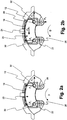
- Fig. 1 recognizes a known disc brake 10 in a perspective view.
- This comprises a housing 12 with a cross member 14 on the housing cross member 14 is a pad retaining spring assembly 16 is arranged.
- Each of the brake pad assemblies 18, 20 includes a plate-like brake pad carrier 22 and a brake pad 24 mounted thereon. Between the two brake pad assemblies 18, 20 runs in the usual Way one in Fig. 1 not shown brake disc, which is rotatably connected to a vehicle wheel to be braked.
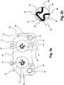
- Fig. 2a It can be seen that the brake pad assembly 20, more precisely, the brake pad carrier 22, in its lower corner regions respectively recesses 26, 28, through the guide pins 30, 32 extend therethrough.
- the recesses 26, 28 are dimensioned with some play relative to the guide pins 30, 32, so that the brake pad assembly 20 can be easily moved on the guide pins 30, 32.
- Fig. 2a is also the direction of rotation D indicated, in which rotates a braked disc when driving forward of the vehicle. Accordingly, the braking torque is directed.
- the brake pad assembly 20 Due to the action of the hold-down spring 16, the brake pad assembly 20 is pressed with the force F 1 on the two bolts 30 and 32, so that below the bolt a clearance between the bolts 30 and 32 and the opposite region of the edge of the recesses 26 and 28 is present , Is braked slightly with the brake, so that a relatively low braking torque acts on the brake pad assembly 20, so also acts the force F 2 , which ensures that the brake pad assembly 20 also rests on the right of the bolt 30 and 32 respectively.
- the invention takes this noise development into account by preventing such an abrupt shift of the brake pad arrangements onto the bolt.
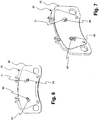
- Fig. 3a shows a view of a brake pad assembly according to the invention on the side facing away from the brake pad side of the brake pad carrier 22. It can be seen how the two recesses 26 and 28 of the brake pad carrier with clearance of the two bolts 30 and 32 are interspersed (now due to the opposite view mirrored to the view according to Fig. 2a and 2b ).
- each fastening pins 34, 36, 38, 40 are mounted on the back.
- the rear side of the brake pad carrier each engage on their front side hollow cylindrical pistons 42, 44 which are hydraulically displaceable in a conventional manner in the Housing 12 of the disc brake 10 are arranged.
- spring elements 46, 48 are mounted on the pins 34, 36 and 38, 40 respectively.
- the spring element 48 will be explained in detail.
- This comprises a clamp-like portion 50, which surrounds the two fastening pins 38, 40.
- the clip-like portion 50 is followed by two legs 52, 54, which have an arcuate course and thus form a constriction similar to the Greek letter " ⁇ ".
- the bracket-like portion 50 and the two legs 52 extend approximately in the plane of the drawing.
- the free ends 56, 58 of the spring element 48 extend out of the plane of the drawing into the frontal opening 60 of the hollow piston 44 (see FIG Fig. 3a ).
- the free ends 56, 58 are biased to the opening 60 delimiting the cylindrical wall and thus clamp the brake pad assembly 20 in an unloaded or only slightly loaded operating situation in a position in accordance with the position Fig.
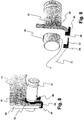
- FIGS. 4 and 5 show an alternative embodiment of the brake pad assembly according to the invention.
- spring elements 62 and 64 made of spring steel, for example, made of a spring steel strip material, attached by screws.
- These spring elements each have two spring arms 66, 68 and 70, 72, which are arranged in pairs at 90 ° to each other and for a bias according to the description FIGS. 3a and 3b to care.
- the spring arms 66, 68 and 70, 72 are each arcuately formed from a base 74 and 76 and elastically resilient in itself. The operation is the same as with reference to FIGS. 3a and 3b described.
- a spring element 80 formed of a spring wire is arranged such that this spring element 80 wraps around the bolt 32 with a loop portion 82, below the bolt 32 is provided a constriction, from the two legs 84, 86 go out, in passing on the front edge 88 of the brake pad carrier 22 along sections 90, 92.
- These sections 90 and 92 have at their free ends angled gripper sections 94, 96 which engage behind the brake pad carrier 22.
- the spring 80 When viewed in the direction of the longitudinal axis of the bolt 32, the spring 80 thus has a ⁇ -shaped form.
- the spring element orthogonal to the longitudinal axis of the bolt 32 is elastically deformable, i. stretchable, and thus ensures a tightening action between the bolt 32 and the brake pad carrier 22. This tightening action is directed so that the bolt 32 comes in contact with the edge of the recess 28 at its bottom in the region of the contact point P.
- the spring element 80 according to FIGS. 8 and 9 can be a targeted pre-positioning of the brake pad carrier 22 relative to the bolt 32 reach, so that abrupt noise-inducing relative movements between these two components can be prevented.
Landscapes
- Engineering & Computer Science (AREA)
- General Engineering & Computer Science (AREA)
- Mechanical Engineering (AREA)
- Braking Arrangements (AREA)
Description
Die vorliegende Erfindung betrifft eine Scheibenbremse für eine Kraftfahrzeugbremsanlage mit einem rahmenartigen Gehäuse, wenigstens zwei in dem rahmenartigen Gehäuse aufgenommenen Bremsbelaganordnungen, zwischen denen eine um eine Drehachse drehbare Bremsscheibe aufnehmbar ist, und wenigstens zwei Führungsbolzen, die an dem Gehäuse angebracht sind und an denen wenigstens eine der Bremsbelaganordnungen mit Spiel in axialer Richtung verlagerbar geführt ist. Derartige Scheibenbremsen sind aus dem Stand der Technik bekannt.The present invention relates to a disc brake for a motor vehicle brake system comprising a frame-like housing, at least two brake pad assemblies received in the frame-like housing, between which a brake disc rotatable about an axis of rotation can be received, and at least two guide pins mounted on the housing and at least one thereof the brake pad assemblies with play in the axial direction is guided displaced. Such disc brakes are known from the prior art.
So beschreibt beispielsweise das Dokument
Es ist Aufgabe der vorliegenden Erfindung, eine Scheibenbremse der eingangs bezeichneten Art bereitzustellen, bei der derartige unerwünschte Geräusche wirkungsvoll unterbunden werden.It is an object of the present invention to provide a disc brake of the type described, are effectively prevented in such unwanted noise.
Diese Aufgabe wird durch eine Scheibenbremse der eingangs bezeichneten Art gelöst, bei der vorgesehen ist, dass an der auf den Führungsbolzen geführten Bremsbelaganordnung wenigstens ein Federmittel angebracht ist, das diese Bremsbelaganordnung relativ zu den Führungsbolzen in eine einer Kippbewegung, die beim Abbremsen der Bremsscheibe aus einem an der Bremsbelaganordnung angreifenden Bremsmoment resultiert, entsprechende Stellung vorspannt.This object is achieved by a disc brake of the type described, in which it is provided that at the guided on the guide pin brake pad assembly at least one spring means is mounted, this brake pad assembly relative to the guide pin in a tilting movement when braking the brake disc from a on the brake pad assembly attacking braking torque results, biasing corresponding position.
Erfindungsgemäß ist demnach vorgesehen, dass die Bremsbelaganordnung über das wenigstens eine Federmittel entsprechend vorgespannt wird, so dass es zu keiner Relativbewegung und auch zu keinem abrupten geräuschinduzierenden Anschlagen in Folge des anwachsenden oder bei Freigabe der Bremse abnehmenden Bremsmoments kommen kann. Dadurch werden störende Geräusche, die durch ein derartiges Anschlagen bedingt sind, wirkungsvoll unterbunden.According to the invention, it is accordingly provided that the brake lining arrangement is pretensioned correspondingly via the at least one spring means, so that there can be no relative movement and also no abrupt noise-inducing impact due to the increasing or decreasing braking torque when the brake is released. As a result, disturbing noises, which are caused by such a striking, effectively prevented.
Gemäß einer Weiterbildung der Erfindung kann vorgesehen sein, dass die Bremsbelaganordnung wenigstens einen Bremsbelagträger und einen auf der der Bremsscheibe zugewandten Seite des Bremsbelagträgers angeordneten Bremsbelag aufweist, wobei das wenigstens eine Federmittel auf der vom Bremsbelag abgewandten Seite des Bremsbelagträgers angeordnet ist. Es versteht sich, dass erfindungsgemäß auch mehrere Federmittel an dem Bremsbelagträger ausgebildet sein können. Der Bremsbelagträger kann seinerseits beispielsweise aus einem plattenförmigen Metallelement hergestellt sein, in dem die Führungsbolzenausnehmungen zum Aufnehmen der Führungsbolzen ausgebildet sein können.According to a development of the invention it can be provided that the brake lining arrangement has at least one brake pad carrier and a brake pad carrier arranged on the side facing the brake pad carrier, wherein the at least one spring means is arranged on the side facing away from the brake pad side of the brake pad carrier. It is understood that according to the invention also a plurality of spring means may be formed on the brake pad carrier. The brake pad carrier can in turn for example from a plate-shaped Be prepared metal element, in which the Führungsbolzenausnehmungen may be formed for receiving the guide pins.
Erfindungsgemäß kann vorgesehen sein, dass die Bremsbelaganordnung auf den Führungsbolzen über ein verlagerbares Stellglied verlagerbar ist, wobei das wenigstens eine Federmittel an dem Stellglied angreift. In diesem Zusammenhang kann vorgesehen sein, dass das Stellglied wenigstens einen stirnseitig hohl ausgebildeten Bremskolben aufweist, in den das wenigstens eine Federmittel eingreift. Dadurch kann der in dem Bremskolben ausgebildete Hohlraum wirkungsvoll für die Unterbringung des wenigstens einen Federmittels ausgenutzt werden.According to the invention it can be provided that the brake pad assembly is displaceable on the guide pin via a displaceable actuator, wherein the at least one spring means engages the actuator. In this context, it can be provided that the actuator has at least one frontally hollow brake piston, in which engages the at least one spring means. Thereby, the cavity formed in the brake piston can be effectively utilized for accommodating the at least one spring means.
Eine bevorzugte Ausführungsvariante der Erfindung sieht vor, dass das Federmittel die Bremsbelaganordnung in verschiedenen Richtungen, beispielsweise sowohl in radialer Richtung als auch in Umfangsrichtung bezüglich der Drehachse vorspannt. Vorzugsweise ist dabei die Richtung der Spannwirkung der Federmittel derart gewählt, dass sie die Bremsbelaganordnung in einer Richtung vorspannt, die einer Verlagerung entspricht, wie sie aufgrund eines zunehmenden Bremsmoments entgegen der Wirkung einer Niederhaltefeder oder einer anderweitig bestimmten Ausgangsposition auftritt, so dass abrupte geräuschinduzierende Verlagerung vermieden werden können.A preferred embodiment of the invention provides that the spring means biases the brake pad assembly in different directions, for example, both in the radial direction and in the circumferential direction with respect to the axis of rotation. Preferably, the direction of the clamping action of the spring means is selected such that it biases the brake pad assembly in a direction corresponding to a displacement, as occurs due to an increasing braking torque against the action of a hold-down spring or an otherwise determined starting position, so that abrupt noise-inducing displacement avoided can be.
Gemäß einer Ausführungsvariante der Erfindung kann vorgesehen sein, dass das Federmittel aus einem Federblech hergestellt ist. Dabei ist es möglich, dass das Federmittel wenigstens einen bogenförmig verlaufenden Federarm aufweist, der über eine Basis an dem Bremsbelagträger befestigt ist. Ferner kann vorgesehen sein, dass zwei oder mehr Federmittel mit ihrer jeweiligen Basis aneinanderliegend an dem Bremsbelagträger angebracht sind, wobei sich ihre Federarme in einem Winkel zueinander erstrecken. Die Basen dieser Federmittel können sozusagen "gestapelt" an dem Bremsbelagträger befestigt werden. Zur Befestigung einer oder mehrerer Basen können eine Schraube, ein Niet, eine (Punkt-)Schweißverbindung oder dergleichen verwendet werden. Die Federarme können je nach Bedarf und gewünschter Kraftausrichtung in vorbestimmter Winkellage zueinander oder/und zum Bremsbelagträger orientiert und an letzterem fixiert werden. Alternativ kann vorgesehen sein, dass das Federmittel wenigstens zwei bogenförmig verlaufende Federarme aufweist, die in einem Winkel von etwa 90° zueinander angeordnet und über eine gemeinsame Basis an dem Bremsbelagträger befestigt sind. Durch Verwendung ein oder mehrerer Federmittel mit mehreren Federarmen lässt sich ein vordefiniertes Kippmoment auf die jeweilige Bremsbelaganordnung ausüben.According to one embodiment of the invention can be provided that the spring means is made of a spring plate. It is possible that the spring means comprises at least one arcuately extending spring arm, which is fastened via a base on the brake pad carrier. Furthermore, it can be provided that two or more spring means are mounted with their respective base adjacent to each other on the brake pad carrier, with their spring arms extending at an angle to each other. The bases of these spring means can be fixed so to speak "stacked" on the brake pad carrier. For fixing one or more bases, a screw, a rivet, a (spot) welded joint or the like may be used. The spring arms can be oriented according to need and desired force alignment in a predetermined angular position to each other and / or to the brake pad carrier and fixed to the latter. Alternatively, it may be provided that the spring means comprises at least two arcuately extending spring arms, which are arranged at an angle of approximately 90 ° to each other and attached via a common base to the brake pad carrier. By using one or more spring means With a plurality of spring arms, a predefined tilting moment can be exerted on the respective brake pad arrangement.
Ferner kann vorgesehen sein, dass das Federmittel aus einem Federdraht hergestellt ist. Dabei ist es erfindungsgemäß möglich, dass das Federmittel rückseitige Befestigungszapfen am Bremsbelagträger klammerartig umgreift und mit seinen freien Enden Federarme bildet. Ferner kann erfindungsgemäß vorgesehen sein, dass der Federdraht um den jeweiligen Führungsbolzen herumgeführt ist und sich mit einem elastisch deformierbaren Abschnitt zu einem Befestigungsbereich an dem Bremsbelagträger hin erstreckt, an dem der Federdraht am Bremsbelagträger angebracht ist. Der Federdraht kann etwa die Form eines Ω annehmen, es sind aber auch andersartige Formen denkbar. Wichtig ist, dass sich das Federmittel elastisch deformieren lässt, um seine Federwirkung entfalten zu können.Furthermore, it can be provided that the spring means is made of a spring wire. In this case, it is possible according to the invention that the spring means surrounds the rear fastening pins on the brake pad carrier like a clip and forms spring arms with its free ends. Furthermore, it can be provided according to the invention that the spring wire is guided around the respective guide pin and extends with an elastically deformable portion to a mounting region on the brake pad carrier, to which the spring wire is attached to the brake pad carrier. The spring wire can take on the shape of an Ω, but there are also other forms conceivable. It is important that the spring means can be deformed elastically in order to develop its spring action.
Zur Anbringung kann vorgesehen sein, dass der Federdraht den Bremsbelagträger an seinem Befestigungsbereich randseitig umklammert.For attachment can be provided that the spring wire clasps the brake pad carrier at the edge of its attachment area.
Die Erfindung betrifft ferner eine Bremsbelaganordnung für eine Scheibenbremse der vorstehend beschriebenen Art, mit einem Bremsbelagträger, an dem ein Bremsbelag angebracht ist, wobei der Bremsbelagträger wenigstens zwei Führungsöffnungen aufweist, die dazu ausgebildet sind, jeweils einen Führungsbolzen aufzunehmen, auf dem sie bei einer Betätigung der Scheibenbremse axial geführt sind, wobei die Bremsbelaganordnung wenigstens ein Federmittel aufweist, das sie in eine einer Kippbewegung relativ zu den Führungsbolzen, die beim Abbremsen der Bremsscheibe aus einem an der Bremsbelaganordnung angreifenden Bremsmoment resultiert, entsprechende Stellung vorspannt.The invention further relates to a brake pad assembly for a disc brake of the type described above, comprising a brake pad carrier to which a brake pad is attached, wherein the brake pad carrier has at least two guide openings which are adapted to receive a respective guide pin on which they upon actuation of the Disc brake are axially guided, wherein the brake pad assembly comprises at least one spring means, which biases it in a tilting movement relative to the guide pin, which results during braking of the brake disc from acting on the brake pad assembly braking torque corresponding position.
Die Erfindung wird im Folgenden beispielhaft anhand der beiliegenden Figuren erläutert. Es stellen dar:
- Fig. 1
- eine perspektivische Ansicht einer erfindungsgemäßen Scheibenbremse mit entsprechenden Bremsbelaganordnungen;
- Fig. 2a
- eine Ansicht einer herkömmlichen Bremsbelaganordnung in der Scheibenbremse gemäß
Fig. 1 bei niedrigem Bremsmoment; - Fig. 2b
- eine Ansicht entsprechend
Fig. 2a , die die Situation bei hohem Bremsmoment darstellt; - Fig. 3a
- eine Ansicht einer Bremsbelaganordnung gemäß einer ersten Ausführungsvariante der Erfindung;
- Fig. 3b
- einen vergrößerten Ausschnitt der
Fig. 3a zur Erläuterung des Federmittels; - Fig. 4 und 5
- Ansichten einer Bremsbelaganordnung einer zweiten Ausführungsform der Erfindung;
- Fig. 6 und 7
- Ansichten einer Bremsbelaganordnung einer dritten Ausführungsform der Erfindung;
- Fig. 8 und 9
- Ansichten einer Bremsbelaganordnung einer vierten Ausführungsform der Erfindung sowie eines Führungsbolzens.
- Fig. 1
- a perspective view of a disc brake according to the invention with corresponding brake pad assemblies;
- Fig. 2a
- a view of a conventional brake pad assembly in the disc brake according to
Fig. 1 at low braking torque; - Fig. 2b
- a view accordingly
Fig. 2a representing the situation at high braking torque; - Fig. 3a
- a view of a brake pad assembly according to a first embodiment of the invention;
- Fig. 3b
- an enlarged section of the
Fig. 3a to explain the spring means; - 4 and 5
- Views of a brake pad assembly of a second embodiment of the invention;
- 6 and 7
- Views of a brake pad assembly of a third embodiment of the invention;
- 8 and 9
- Views of a brake pad assembly of a fourth embodiment of the invention and a guide pin.
In
In
In
Wird nun bei dieser an sich bekannten Anordnung das Bremsmoment erhöht, so ergibt sich ein Kippmoment auf die Bremsbelaganordnung 20, wobei die Wirkung der Niederhaltefeder 16 überwunden wird. Dieses Kippmoment ergibt sich aus der verhältnismäßig großen Reibkraft FR, die durch Anpressen des Bremsbelags 24 der Bremsbelaganordnung 20 erzeugt wird. Aufgrund dieses Kippmoments kommt es zu einer Relativbewegung zwischen der Bremsbelaganordnung 20 und dem Bolzen 32. Genauer gesagt dreht sich aufgrund des Kippmoments entgegen der Wirkung der Niederhaltefeder 16 die Bremsbelaganordnung 20 um den Bolzen 30 herum, so dass unter Aufbrauchen des Spiels zwischen dem Bolzen 32 und der Ausnehmung 28 schließlich der Rand der Ausnehmung 28 am unteren Bereich des Bolzens 32 zur Anlage kommt. Beim Stand der Technik wurde diese Relativverlagerung der Bremsbelaganordnung 20 relativ zu den Bolzen 30, 32 von dem Zustand gemäß
Die Erfindung trägt dieser Geräuschentwicklung Rechnung, indem eine solche abrupte Verlagerung der Bremsbelaganordnungen auf den Bolzen unterbunden wird.The invention takes this noise development into account by preventing such an abrupt shift of the brake pad arrangements onto the bolt.
Mit Bezug auf
Diese unterscheidet sich von der Ausführungsform gemäß
Ferner sei darauf hingewiesen, dass eine "Mehrarm-Lösung", wie sie in
Dabei erkennt man, dass am Bolzen 32, der in der Ausnehmung 28 geführt ist, ein aus einem Federdraht geformtes Federelement 80 derart angeordnet ist, dass dieses Federelement 80 mit einem Schlaufenabschnitt 82 den Bolzen 32 umschlingt, unterhalb des Bolzens 32 eine Einschnürung vorgesehen ist, von der zwei Schenkel 84, 86 ausgehen, die in an der Stirnkante 88 des Bremsbelagträgers 22 entlang laufende Abschnitte 90, 92 übergehen. Diese Abschnitte 90 bzw. 92 weisen an ihren freien Enden abgewinkelte Greiferabschnitte 94, 96 auf, die den Bremsbelagträger 22 hintergreifen.It can be seen that on the
In Richtung der Längsachse des Bolzens 32 betrachtet, weist somit die Feder 80 Ωförmige Gestalt auf. Durch den eingeschnürten Übergangsbereich zwischen dem Abschnitt 82 und den Schenkeln 84, 86 ist das Federelement orthogonal zur Längsachse des Bolzens 32 elastische deformierbar, d.h. streckbar, und sorgt so für eine Anzugwirkung zwischen dem Bolzen 32 und dem Bremsbelagträger 22. Diese Anzugwirkung ist so gerichtet, dass der Bolzen 32 an seiner Unterseite im Bereich des Kontaktpunkts P in Anlage mit dem Rand der Ausnehmung 28 kommt.When viewed in the direction of the longitudinal axis of the
Auch mit der Ausgestaltung des Federelements 80 gemäß
Claims (13)
- Disk brake (10) for a motor vehicle brake system having- a frame-like housing (12),- at least two brake pad arrangements (18, 20), which are accommodated in the frame-like housing (12) and between which a brake disk that is rotatable about an axis of rotation may be accommodated, and- at least two guide bolts (30, 32), which are mounted on the housing (12) and on which at least one of the brake pad arrangements (18, 20) is guided with play in an axially displaceable manner,characterized in that on the brake pad arrangement (18, 20) guided on the guide bolts (30, 32) at least one spring means (46, 48) is mounted, which biases said brake pad arrangement (18, 20) relative to the guide bolts (30, 32) into a position corresponding to a tilting movement that results during braking of the brake disk from a braking torque acting on the brake pad arrangement (18, 20), wherein the brake pad arrangement (18, 20) comprises at least one brake pad carrier (22) and a brake pad (24) disposed at the side of the brake pad carrier (22) facing the brake disk, wherein the at least one spring means (46, 48) is disposed at the side of the brake pad carrier (22) remote from the brake pad (24).
- Disk brake (10) according to claim 1,
characterized in that the brake pad arrangement (18, 20) is displaceable on the guide bolts (30, 32) by means of a displaceable actuator (40, 42), wherein the at least one spring means (46, 48) acts on the actuator (40, 42). - Disk brake (10) according to claim 2,
characterized in that the actuator (40, 42) comprises at least one brake piston, which is designed with a hollow end and into which the at least one spring means (46, 48) engages. - Disk brake (10) according to claim 1,
characterized in that the spring means (46, 48) biases the brake pad arrangement (18, 20) both in radial direction and in peripheral direction relative to the axis of rotation. - Disk brake (10) according to claim 1,
characterized in that the spring means (46, 48) is manufactured from a spring steel sheet. - Disk brake (10) according to claim 5,
characterized in that the spring means (46, 48) comprises at least one spring arm (66, 68, 70, 72; 67, 71), which extends in an arc-shaped manner and is fastened by a base (62, 64) to the brake pad carrier (22). - Disk brake (10) according to claim 6,
characterized in that two or more spring means (46, 48) are mounted by their respective base adjacent to one another on the brake pad carrier (22), wherein their spring arms extend at an angle to one another. - Disk brake (10) according to claim 6,
characterized in that the spring means (46, 48) comprises two spring arms (66, 68, 70, 72), which extend in an arc-shaped manner and at the base are disposed at an angle of approximately 90°. - Disk brake (10) according to claim 1,
characterized in that the spring means (46, 48) is manufactured from a spring wire. - Disk brake (10) according to claim 9,
characterized in that the spring means (46, 48) engages in a clamp-like manner around rear fastening pins (34, 36, 38, 40) on the brake pad carrier (22) and with its free ends forms spring arms (56, 58). - Disk brake (10) according to claim 9,
characterized in that the spring wire is conveyed around the respective guide bolt (32) and extends with an elastically deformable portion (84, 86) in the direction of a fastening region on the brake pad carrier (22), at which the spring wire is mounted on the brake pad carrier (22). - Disk brake (10) according to claim 11, wherein the spring wire is clamped round the edge of the brake pad carrier (22) at the fastening region thereof.
- Brake pad arrangement (20) for a Disk brake (10) according to claim 1, comprising a brake pad carrier (22), on which a brake pad (24) is mounted, wherein the brake pad carrier (22) has at least two guide openings (26, 28) that are designed to receive in each case a guide bolt (30, 32), on which they are axially guided upon an actuation of the Disk brake (10), wherein the brake pad arrangement (20) comprises at least one spring means (46, 48) that biases it relative to the guide bolts (30, 32) into a position corresponding to a tilting movement that results during braking of the brake disk from a braking torque acting on the brake pad arrangement (20).
Applications Claiming Priority (2)
| Application Number | Priority Date | Filing Date | Title |
|---|---|---|---|
| DE102008058265A DE102008058265A1 (en) | 2008-11-20 | 2008-11-20 | Disc brake and brake pad assembly for this |
| PCT/EP2009/008150 WO2010057608A2 (en) | 2008-11-20 | 2009-11-16 | Disk brake and brake pad arrangement therefor |
Publications (3)
| Publication Number | Publication Date |
|---|---|
| EP2350488A2 EP2350488A2 (en) | 2011-08-03 |
| EP2350488B1 true EP2350488B1 (en) | 2018-01-10 |
| EP2350488B2 EP2350488B2 (en) | 2020-11-11 |
Family
ID=42109775
Family Applications (1)
| Application Number | Title | Priority Date | Filing Date |
|---|---|---|---|
| EP09753049.7A Not-in-force EP2350488B2 (en) | 2008-11-20 | 2009-11-16 | Disk brake and brake pad arrangement therefor |
Country Status (5)
| Country | Link |
|---|---|
| US (1) | US8517152B2 (en) |
| EP (1) | EP2350488B2 (en) |
| CN (1) | CN102224357B (en) |
| DE (1) | DE102008058265A1 (en) |
| WO (1) | WO2010057608A2 (en) |
Families Citing this family (16)
| Publication number | Priority date | Publication date | Assignee | Title |
|---|---|---|---|---|
| DE102008058265A1 (en) | 2008-11-20 | 2010-05-27 | Lucas Automotive Gmbh | Disc brake and brake pad assembly for this |
| USD692356S1 (en) * | 2011-04-26 | 2013-10-29 | Dr. Ing. H.C. F. Porsche Aktiengesellschaft | Vehicle brake |
| DE102011118313B4 (en) * | 2011-11-11 | 2013-09-26 | Wabco Radbremsen Gmbh | DISC BRAKE, ESPECIALLY FOR COMMERCIAL VEHICLES, AS WELL AS BRAKE PAD AND PRESSURE PLATE AS SEPARATE COMPONENTS FOR SUCH A DISC BRAKE |
| US9068610B2 (en) * | 2012-12-11 | 2015-06-30 | Arvinmeritor Technology, Llc | Brake caliper assembly having a spacer tape and a method of manufacture |
| DE102013008161A1 (en) * | 2013-05-13 | 2014-11-13 | Wabco Europe Bvba | Caliper disc brake of a vehicle, especially a commercial vehicle, and caliper of such a brake |
| US20150041259A1 (en) * | 2013-08-09 | 2015-02-12 | Akebono Brake Industry Co., Ltd. | Pin hole shape in a pressure plate |
| JP5855615B2 (en) * | 2013-09-06 | 2016-02-09 | 日信工業株式会社 | Vehicle disc brake |
| FR3027081B1 (en) * | 2014-10-10 | 2016-12-23 | Chassis Brakes Int Bv | "SLIDING CALIPER DISC BRAKE COMPRISING A CENTRAL SPRING OF ELASTIC RECALL OF AN EXTERNAL BRAKE SKATE COMPRISING MEANS OF RETRACTING THE WEAR SET, SPRING AND REPLACEMENT KIT" |
| EP3250839B1 (en) * | 2015-01-30 | 2022-04-13 | BREMBO S.p.A. | Pad and spring assembly for a disc brake caliper |
| DE102016209069A1 (en) | 2015-08-31 | 2017-03-02 | Continental Teves Ag & Co. Ohg | Back plate for a disc brake pad, disc brake pad and fixed caliper disc brake |
| DE102015122569A1 (en) * | 2015-12-22 | 2017-06-22 | Bpw Bergische Achsen Kg | Disc brake, brake pad for a disc brake, hold-down for attaching brake pads |
| ITUA20162181A1 (en) | 2016-03-31 | 2017-10-01 | Freni Brembo Spa | TABLETS, SETS, CALIPER AND METHOD FOR DISC BRAKE |
| DE102018002886A1 (en) * | 2018-04-10 | 2019-10-10 | Lucas Automotive Gmbh | Brake pad arrangement for a disc brake of a vehicle brake system |
| JP7426245B2 (en) | 2020-01-15 | 2024-02-01 | 曙ブレーキ工業株式会社 | Disc brake pad and disc brake device with pin holder |
| DE102020106296A1 (en) * | 2020-03-09 | 2021-09-23 | Tmd Friction Services Gmbh | Lining carrier plate for a disc brake of a motor vehicle and a method for its production |
| CN120969376B (en) * | 2025-10-21 | 2026-01-02 | 浙江万安科技股份有限公司 | Vehicle control device and vehicle |
Citations (14)
| Publication number | Priority date | Publication date | Assignee | Title |
|---|---|---|---|---|
| FR2371606A1 (en) | 1976-11-19 | 1978-06-16 | Girling Ltd | Brake block for disc brakes - is attached to brake mounting by spring embedded in friction lining guide to prevent rattling |
| EP0563555A1 (en) | 1992-04-01 | 1993-10-06 | Dr.Ing.h.c. F. Porsche Aktiengesellschaft | Device for damping vibrations of brake linings |
| DE4304616A1 (en) | 1993-02-16 | 1994-08-18 | Daimler Benz Ag | Disc brake for the wheels of a motor vehicle |
| DE4318744C1 (en) | 1993-06-05 | 1994-09-01 | Teves Gmbh Alfred | Floating calliper disc brake for motor vehicles |
| DE4332709A1 (en) | 1993-09-25 | 1995-03-30 | Teves Gmbh Alfred | Floating-caliper disc brake which cannot be fitted with the wrong pads |
| US5577577A (en) | 1994-11-07 | 1996-11-26 | Sumitomo Electric Industries, Ltd. | Floating caliper type disc brake having noise reducing torque carrying structure |
| JPH0942337A (en) | 1995-08-03 | 1997-02-10 | Sumitomo Electric Ind Ltd | Pad presser spring for disc brake |
| EP0851139A1 (en) | 1996-12-27 | 1998-07-01 | Sumitomo Electric Industries, Ltd. | Disk brake |
| DE10312479A1 (en) | 2003-03-20 | 2004-10-14 | Lucas Automotive Gmbh | disc brake |
| WO2007062420A1 (en) | 2005-11-28 | 2007-05-31 | Hb Performance Systems, Inc. | Positive pad retraction and retention device |
| GB2434624A (en) | 2006-01-27 | 2007-08-01 | Trw Ltd | Brake pad arrangement for a disc brake |
| EP1700047B1 (en) | 2003-12-30 | 2007-10-24 | Freni Brembo S.p.A. | Brake pad and caliper for a disc brake |
| WO2010057608A2 (en) | 2008-11-20 | 2010-05-27 | Lucas Automotive Gmbh | Disk brake and brake pad arrangement therefor |
| EP2274532B1 (en) | 2008-05-06 | 2012-02-01 | Lucas Automotive GmbH | Brake lining arrangement for disc brakes |
Family Cites Families (8)
| Publication number | Priority date | Publication date | Assignee | Title |
|---|---|---|---|---|
| GB1590631A (en) * | 1976-11-19 | 1981-06-03 | Girling Ltd | Disc brakes |
| AU6759981A (en) * | 1980-03-01 | 1981-09-10 | Lucas Industries Limited | Disc brakes and friction pad assemblies therefor |
| JPH07109224B2 (en) * | 1990-05-18 | 1995-11-22 | 日清紡績株式会社 | Disc brake |
| DE4126197A1 (en) | 1991-08-08 | 1993-02-11 | Teves Gmbh Alfred | FLOATING FRAME DISC BRAKE WITH COMFORTABLE BRAKE SHOE ARRANGEMENT |
| DE4240872A1 (en) * | 1992-12-04 | 1994-06-09 | Teves Gmbh Alfred | Brake pad for disc brakes - has triple-tongued holding down spring with longer tongue bent U=shaped round axis of brake piston |
| FR2735195B1 (en) * | 1995-06-08 | 1998-01-30 | Alliedsignal Europ Services | DISC BRAKE USING A ROTATING LOADED PAD |
| DE19935036C1 (en) | 1999-07-26 | 2001-02-08 | Lucas Ind Plc | Brake lining retaining spring at a disk brake is a spring wire with two coils at supports for the brake linings locked into notches at the brake carrier to carry large or additional brake linings |
| DE10159504B4 (en) * | 2001-12-04 | 2010-10-21 | Dr. Ing. H.C. F. Porsche Aktiengesellschaft | Parking brake |
-
2008
- 2008-11-20 DE DE102008058265A patent/DE102008058265A1/en not_active Withdrawn
-
2009
- 2009-11-16 WO PCT/EP2009/008150 patent/WO2010057608A2/en not_active Ceased
- 2009-11-16 CN CN2009801463968A patent/CN102224357B/en not_active Expired - Fee Related
- 2009-11-16 EP EP09753049.7A patent/EP2350488B2/en not_active Not-in-force
- 2009-11-16 US US13/129,871 patent/US8517152B2/en not_active Expired - Fee Related
Patent Citations (14)
| Publication number | Priority date | Publication date | Assignee | Title |
|---|---|---|---|---|
| FR2371606A1 (en) | 1976-11-19 | 1978-06-16 | Girling Ltd | Brake block for disc brakes - is attached to brake mounting by spring embedded in friction lining guide to prevent rattling |
| EP0563555A1 (en) | 1992-04-01 | 1993-10-06 | Dr.Ing.h.c. F. Porsche Aktiengesellschaft | Device for damping vibrations of brake linings |
| DE4304616A1 (en) | 1993-02-16 | 1994-08-18 | Daimler Benz Ag | Disc brake for the wheels of a motor vehicle |
| DE4318744C1 (en) | 1993-06-05 | 1994-09-01 | Teves Gmbh Alfred | Floating calliper disc brake for motor vehicles |
| DE4332709A1 (en) | 1993-09-25 | 1995-03-30 | Teves Gmbh Alfred | Floating-caliper disc brake which cannot be fitted with the wrong pads |
| US5577577A (en) | 1994-11-07 | 1996-11-26 | Sumitomo Electric Industries, Ltd. | Floating caliper type disc brake having noise reducing torque carrying structure |
| JPH0942337A (en) | 1995-08-03 | 1997-02-10 | Sumitomo Electric Ind Ltd | Pad presser spring for disc brake |
| EP0851139A1 (en) | 1996-12-27 | 1998-07-01 | Sumitomo Electric Industries, Ltd. | Disk brake |
| DE10312479A1 (en) | 2003-03-20 | 2004-10-14 | Lucas Automotive Gmbh | disc brake |
| EP1700047B1 (en) | 2003-12-30 | 2007-10-24 | Freni Brembo S.p.A. | Brake pad and caliper for a disc brake |
| WO2007062420A1 (en) | 2005-11-28 | 2007-05-31 | Hb Performance Systems, Inc. | Positive pad retraction and retention device |
| GB2434624A (en) | 2006-01-27 | 2007-08-01 | Trw Ltd | Brake pad arrangement for a disc brake |
| EP2274532B1 (en) | 2008-05-06 | 2012-02-01 | Lucas Automotive GmbH | Brake lining arrangement for disc brakes |
| WO2010057608A2 (en) | 2008-11-20 | 2010-05-27 | Lucas Automotive Gmbh | Disk brake and brake pad arrangement therefor |
Also Published As
| Publication number | Publication date |
|---|---|
| EP2350488A2 (en) | 2011-08-03 |
| DE102008058265A1 (en) | 2010-05-27 |
| WO2010057608A2 (en) | 2010-05-27 |
| US8517152B2 (en) | 2013-08-27 |
| US20110226566A1 (en) | 2011-09-22 |
| EP2350488B2 (en) | 2020-11-11 |
| WO2010057608A3 (en) | 2010-07-15 |
| CN102224357A (en) | 2011-10-19 |
| CN102224357B (en) | 2013-08-21 |
Similar Documents
| Publication | Publication Date | Title |
|---|---|---|
| EP2350488B1 (en) | Disk brake and brake pad arrangement therefor | |
| DE1450130C3 (en) | Hydraulically operated partially lined disc brake | |
| EP1963702B1 (en) | Brake lining for a disc brake | |
| DE102009038317B4 (en) | Adjustable steering column for a motor vehicle | |
| DE69919100T2 (en) | GAS PEDAL MECHANISM FOR VEHICLE | |
| EP3077694B1 (en) | Drum brake module which can be operated by electric motor | |
| DE19953159A1 (en) | Disc brake assembly for motor vehicle allows controlled movement of brake linings, minimizing noise, using two brake interfaces with inclined surfaces, and supporting element which rides on rotor | |
| EP2644926B1 (en) | Disc brake comprising a reset mechanism, and corresponding brake lining | |
| DE19544340C2 (en) | Mounting bracket for a pressure fluid damper device | |
| EP1759126A1 (en) | Disk brake with a spring arrangement | |
| WO2011076424A1 (en) | Disc brake for a motor vehicle and brake pad assembly therefor | |
| DE202006021160U1 (en) | Adjustable steering column for a motor vehicle | |
| DE1967110A1 (en) | PARTIAL DISC BRAKE IN PARTICULAR FOR MOTOR VEHICLES | |
| DE102010036169B4 (en) | clutch disc | |
| DE102009033394A1 (en) | Pneumatically or electromechanically actuated disc brake | |
| DE102016226054A1 (en) | Leaf spring for caliper and caliper body with such a spring | |
| EP3609770B1 (en) | Steering column comprising an energy absorption device for a motor vehicle | |
| DE3920188C2 (en) | friction clutch | |
| DE2828618A1 (en) | SPRING DEVICE FOR A DRUM BRAKE | |
| DE102005063000A1 (en) | Electric motor linear drive for furniture, has wrap around spring attached on distributor sleeve that is attached on cylindrical attachment, where sleeve comprises material with high stability than that of plastic of worm wheel | |
| DE4101599A1 (en) | Brake block for disc brakes - has relative play between damping plate and fixing projections to compensate for high temperatures | |
| DE19803123B4 (en) | Disc brake with a spring element | |
| EP3685069B1 (en) | Disc brake actuator | |
| DE102012111171A1 (en) | Disc brake e.g. sliding-caliper disc brake for use in commercial vehicle, comprises a traction unit which has two strands, in which one of the strands is operatively connected with a tensioning element | |
| DE102022116789A1 (en) | Disc brake and brake pad arrangement as well as pad spring and hold-down element for this |
Legal Events
| Date | Code | Title | Description |
|---|---|---|---|
| PUAI | Public reference made under article 153(3) epc to a published international application that has entered the european phase |
Free format text: ORIGINAL CODE: 0009012 |
|
| 17P | Request for examination filed |
Effective date: 20110518 |
|
| AK | Designated contracting states |
Kind code of ref document: A2 Designated state(s): AT BE BG CH CY CZ DE DK EE ES FI FR GB GR HR HU IE IS IT LI LT LU LV MC MK MT NL NO PL PT RO SE SI SK SM TR |
|
| DAX | Request for extension of the european patent (deleted) | ||
| GRAP | Despatch of communication of intention to grant a patent |
Free format text: ORIGINAL CODE: EPIDOSNIGR1 |
|
| STAA | Information on the status of an ep patent application or granted ep patent |
Free format text: STATUS: GRANT OF PATENT IS INTENDED |
|
| INTG | Intention to grant announced |
Effective date: 20170620 |
|
| GRAS | Grant fee paid |
Free format text: ORIGINAL CODE: EPIDOSNIGR3 |
|
| GRAA | (expected) grant |
Free format text: ORIGINAL CODE: 0009210 |
|
| STAA | Information on the status of an ep patent application or granted ep patent |
Free format text: STATUS: THE PATENT HAS BEEN GRANTED |
|
| AK | Designated contracting states |
Kind code of ref document: B1 Designated state(s): AT BE BG CH CY CZ DE DK EE ES FI FR GB GR HR HU IE IS IT LI LT LU LV MC MK MT NL NO PL PT RO SE SI SK SM TR |
|
| REG | Reference to a national code |
Ref country code: GB Ref legal event code: FG4D Free format text: NOT ENGLISH |
|
| REG | Reference to a national code |
Ref country code: CH Ref legal event code: EP Ref country code: AT Ref legal event code: REF Ref document number: 962756 Country of ref document: AT Kind code of ref document: T Effective date: 20180115 |
|
| REG | Reference to a national code |
Ref country code: IE Ref legal event code: FG4D Free format text: LANGUAGE OF EP DOCUMENT: GERMAN |
|
| REG | Reference to a national code |
Ref country code: DE Ref legal event code: R096 Ref document number: 502009014667 Country of ref document: DE |
|
| REG | Reference to a national code |
Ref country code: NL Ref legal event code: MP Effective date: 20180110 |
|
| PG25 | Lapsed in a contracting state [announced via postgrant information from national office to epo] |
Ref country code: NL Free format text: LAPSE BECAUSE OF FAILURE TO SUBMIT A TRANSLATION OF THE DESCRIPTION OR TO PAY THE FEE WITHIN THE PRESCRIBED TIME-LIMIT Effective date: 20180110 |
|
| PG25 | Lapsed in a contracting state [announced via postgrant information from national office to epo] |
Ref country code: ES Free format text: LAPSE BECAUSE OF FAILURE TO SUBMIT A TRANSLATION OF THE DESCRIPTION OR TO PAY THE FEE WITHIN THE PRESCRIBED TIME-LIMIT Effective date: 20180110 Ref country code: CY Free format text: LAPSE BECAUSE OF FAILURE TO SUBMIT A TRANSLATION OF THE DESCRIPTION OR TO PAY THE FEE WITHIN THE PRESCRIBED TIME-LIMIT Effective date: 20180110 Ref country code: FI Free format text: LAPSE BECAUSE OF FAILURE TO SUBMIT A TRANSLATION OF THE DESCRIPTION OR TO PAY THE FEE WITHIN THE PRESCRIBED TIME-LIMIT Effective date: 20180110 Ref country code: LT Free format text: LAPSE BECAUSE OF FAILURE TO SUBMIT A TRANSLATION OF THE DESCRIPTION OR TO PAY THE FEE WITHIN THE PRESCRIBED TIME-LIMIT Effective date: 20180110 Ref country code: HR Free format text: LAPSE BECAUSE OF FAILURE TO SUBMIT A TRANSLATION OF THE DESCRIPTION OR TO PAY THE FEE WITHIN THE PRESCRIBED TIME-LIMIT Effective date: 20180110 Ref country code: NO Free format text: LAPSE BECAUSE OF FAILURE TO SUBMIT A TRANSLATION OF THE DESCRIPTION OR TO PAY THE FEE WITHIN THE PRESCRIBED TIME-LIMIT Effective date: 20180410 |
|
| PG25 | Lapsed in a contracting state [announced via postgrant information from national office to epo] |
Ref country code: BG Free format text: LAPSE BECAUSE OF FAILURE TO SUBMIT A TRANSLATION OF THE DESCRIPTION OR TO PAY THE FEE WITHIN THE PRESCRIBED TIME-LIMIT Effective date: 20180410 Ref country code: PL Free format text: LAPSE BECAUSE OF FAILURE TO SUBMIT A TRANSLATION OF THE DESCRIPTION OR TO PAY THE FEE WITHIN THE PRESCRIBED TIME-LIMIT Effective date: 20180110 Ref country code: LV Free format text: LAPSE BECAUSE OF FAILURE TO SUBMIT A TRANSLATION OF THE DESCRIPTION OR TO PAY THE FEE WITHIN THE PRESCRIBED TIME-LIMIT Effective date: 20180110 Ref country code: SE Free format text: LAPSE BECAUSE OF FAILURE TO SUBMIT A TRANSLATION OF THE DESCRIPTION OR TO PAY THE FEE WITHIN THE PRESCRIBED TIME-LIMIT Effective date: 20180110 Ref country code: GR Free format text: LAPSE BECAUSE OF FAILURE TO SUBMIT A TRANSLATION OF THE DESCRIPTION OR TO PAY THE FEE WITHIN THE PRESCRIBED TIME-LIMIT Effective date: 20180411 Ref country code: IS Free format text: LAPSE BECAUSE OF FAILURE TO SUBMIT A TRANSLATION OF THE DESCRIPTION OR TO PAY THE FEE WITHIN THE PRESCRIBED TIME-LIMIT Effective date: 20180510 |
|
| PG25 | Lapsed in a contracting state [announced via postgrant information from national office to epo] |
Ref country code: MT Free format text: LAPSE BECAUSE OF FAILURE TO SUBMIT A TRANSLATION OF THE DESCRIPTION OR TO PAY THE FEE WITHIN THE PRESCRIBED TIME-LIMIT Effective date: 20180110 |
|
| REG | Reference to a national code |
Ref country code: DE Ref legal event code: R026 Ref document number: 502009014667 Country of ref document: DE |
|
| PLBI | Opposition filed |
Free format text: ORIGINAL CODE: 0009260 |
|
| PG25 | Lapsed in a contracting state [announced via postgrant information from national office to epo] |
Ref country code: RO Free format text: LAPSE BECAUSE OF FAILURE TO SUBMIT A TRANSLATION OF THE DESCRIPTION OR TO PAY THE FEE WITHIN THE PRESCRIBED TIME-LIMIT Effective date: 20180110 Ref country code: IT Free format text: LAPSE BECAUSE OF FAILURE TO SUBMIT A TRANSLATION OF THE DESCRIPTION OR TO PAY THE FEE WITHIN THE PRESCRIBED TIME-LIMIT Effective date: 20180110 Ref country code: EE Free format text: LAPSE BECAUSE OF FAILURE TO SUBMIT A TRANSLATION OF THE DESCRIPTION OR TO PAY THE FEE WITHIN THE PRESCRIBED TIME-LIMIT Effective date: 20180110 |
|
| PLAX | Notice of opposition and request to file observation + time limit sent |
Free format text: ORIGINAL CODE: EPIDOSNOBS2 |
|
| 26 | Opposition filed |
Opponent name: VRI-VERBAND DER REIBBELAGINDUSTRIE E.V. Effective date: 20181010 |
|
| PG25 | Lapsed in a contracting state [announced via postgrant information from national office to epo] |
Ref country code: SM Free format text: LAPSE BECAUSE OF FAILURE TO SUBMIT A TRANSLATION OF THE DESCRIPTION OR TO PAY THE FEE WITHIN THE PRESCRIBED TIME-LIMIT Effective date: 20180110 Ref country code: DK Free format text: LAPSE BECAUSE OF FAILURE TO SUBMIT A TRANSLATION OF THE DESCRIPTION OR TO PAY THE FEE WITHIN THE PRESCRIBED TIME-LIMIT Effective date: 20180110 Ref country code: CZ Free format text: LAPSE BECAUSE OF FAILURE TO SUBMIT A TRANSLATION OF THE DESCRIPTION OR TO PAY THE FEE WITHIN THE PRESCRIBED TIME-LIMIT Effective date: 20180110 Ref country code: SK Free format text: LAPSE BECAUSE OF FAILURE TO SUBMIT A TRANSLATION OF THE DESCRIPTION OR TO PAY THE FEE WITHIN THE PRESCRIBED TIME-LIMIT Effective date: 20180110 |
|
| PLBB | Reply of patent proprietor to notice(s) of opposition received |
Free format text: ORIGINAL CODE: EPIDOSNOBS3 |
|
| PG25 | Lapsed in a contracting state [announced via postgrant information from national office to epo] |
Ref country code: SI Free format text: LAPSE BECAUSE OF FAILURE TO SUBMIT A TRANSLATION OF THE DESCRIPTION OR TO PAY THE FEE WITHIN THE PRESCRIBED TIME-LIMIT Effective date: 20180110 |
|
| PGFP | Annual fee paid to national office [announced via postgrant information from national office to epo] |
Ref country code: FR Payment date: 20181127 Year of fee payment: 10 Ref country code: GB Payment date: 20181127 Year of fee payment: 10 |
|
| REG | Reference to a national code |
Ref country code: CH Ref legal event code: PL |
|
| PG25 | Lapsed in a contracting state [announced via postgrant information from national office to epo] |
Ref country code: MC Free format text: LAPSE BECAUSE OF FAILURE TO SUBMIT A TRANSLATION OF THE DESCRIPTION OR TO PAY THE FEE WITHIN THE PRESCRIBED TIME-LIMIT Effective date: 20180110 Ref country code: LU Free format text: LAPSE BECAUSE OF NON-PAYMENT OF DUE FEES Effective date: 20181116 |
|
| REG | Reference to a national code |
Ref country code: BE Ref legal event code: MM Effective date: 20181130 |
|
| REG | Reference to a national code |
Ref country code: IE Ref legal event code: MM4A |
|
| PG25 | Lapsed in a contracting state [announced via postgrant information from national office to epo] |
Ref country code: CH Free format text: LAPSE BECAUSE OF NON-PAYMENT OF DUE FEES Effective date: 20181130 Ref country code: LI Free format text: LAPSE BECAUSE OF NON-PAYMENT OF DUE FEES Effective date: 20181130 |
|
| PG25 | Lapsed in a contracting state [announced via postgrant information from national office to epo] |
Ref country code: IE Free format text: LAPSE BECAUSE OF NON-PAYMENT OF DUE FEES Effective date: 20181116 |
|
| PG25 | Lapsed in a contracting state [announced via postgrant information from national office to epo] |
Ref country code: BE Free format text: LAPSE BECAUSE OF NON-PAYMENT OF DUE FEES Effective date: 20181130 |
|
| REG | Reference to a national code |
Ref country code: AT Ref legal event code: MM01 Ref document number: 962756 Country of ref document: AT Kind code of ref document: T Effective date: 20181116 |
|
| PG25 | Lapsed in a contracting state [announced via postgrant information from national office to epo] |
Ref country code: AT Free format text: LAPSE BECAUSE OF NON-PAYMENT OF DUE FEES Effective date: 20181116 |
|
| PG25 | Lapsed in a contracting state [announced via postgrant information from national office to epo] |
Ref country code: TR Free format text: LAPSE BECAUSE OF FAILURE TO SUBMIT A TRANSLATION OF THE DESCRIPTION OR TO PAY THE FEE WITHIN THE PRESCRIBED TIME-LIMIT Effective date: 20180110 |
|
| PG25 | Lapsed in a contracting state [announced via postgrant information from national office to epo] |
Ref country code: PT Free format text: LAPSE BECAUSE OF FAILURE TO SUBMIT A TRANSLATION OF THE DESCRIPTION OR TO PAY THE FEE WITHIN THE PRESCRIBED TIME-LIMIT Effective date: 20180110 |
|
| PG25 | Lapsed in a contracting state [announced via postgrant information from national office to epo] |
Ref country code: HU Free format text: LAPSE BECAUSE OF FAILURE TO SUBMIT A TRANSLATION OF THE DESCRIPTION OR TO PAY THE FEE WITHIN THE PRESCRIBED TIME-LIMIT; INVALID AB INITIO Effective date: 20091116 Ref country code: MK Free format text: LAPSE BECAUSE OF NON-PAYMENT OF DUE FEES Effective date: 20180110 |
|
| GBPC | Gb: european patent ceased through non-payment of renewal fee |
Effective date: 20191116 |
|
| PUAH | Patent maintained in amended form |
Free format text: ORIGINAL CODE: 0009272 |
|
| STAA | Information on the status of an ep patent application or granted ep patent |
Free format text: STATUS: PATENT MAINTAINED AS AMENDED |
|
| PG25 | Lapsed in a contracting state [announced via postgrant information from national office to epo] |
Ref country code: FR Free format text: LAPSE BECAUSE OF NON-PAYMENT OF DUE FEES Effective date: 20191130 Ref country code: GB Free format text: LAPSE BECAUSE OF NON-PAYMENT OF DUE FEES Effective date: 20191116 |
|
| RAP2 | Party data changed (patent owner data changed or rights of a patent transferred) |
Owner name: ZF ACTIVE SAFETY GMBH |
|
| 27A | Patent maintained in amended form |
Effective date: 20201111 |
|
| AK | Designated contracting states |
Kind code of ref document: B2 Designated state(s): AT BE BG CH CY CZ DE DK EE ES FI FR GB GR HR HU IE IS IT LI LT LU LV MC MK MT NL NO PL PT RO SE SI SK SM TR |
|
| REG | Reference to a national code |
Ref country code: DE Ref legal event code: R102 Ref document number: 502009014667 Country of ref document: DE |
|
| PGFP | Annual fee paid to national office [announced via postgrant information from national office to epo] |
Ref country code: DE Payment date: 20201127 Year of fee payment: 12 |
|
| REG | Reference to a national code |
Ref country code: DE Ref legal event code: R119 Ref document number: 502009014667 Country of ref document: DE |
|
| PG25 | Lapsed in a contracting state [announced via postgrant information from national office to epo] |
Ref country code: DE Free format text: LAPSE BECAUSE OF NON-PAYMENT OF DUE FEES Effective date: 20220601 |