JP7426245B2 - Disc brake pad and disc brake device with pin holder - Google Patents
Disc brake pad and disc brake device with pin holder Download PDFInfo
- Publication number
- JP7426245B2 JP7426245B2 JP2020004654A JP2020004654A JP7426245B2 JP 7426245 B2 JP7426245 B2 JP 7426245B2 JP 2020004654 A JP2020004654 A JP 2020004654A JP 2020004654 A JP2020004654 A JP 2020004654A JP 7426245 B2 JP7426245 B2 JP 7426245B2
- Authority
- JP
- Japan
- Prior art keywords
- pin
- disc brake
- plate
- pad
- main body
- Prior art date
- Legal status (The legal status is an assumption and is not a legal conclusion. Google has not performed a legal analysis and makes no representation as to the accuracy of the status listed.)
- Active
Links
- 238000003780 insertion Methods 0.000 claims description 195
- 230000037431 insertion Effects 0.000 claims description 195
- 230000002093 peripheral effect Effects 0.000 claims description 59
- 238000005452 bending Methods 0.000 claims description 21
- 239000002783 friction material Substances 0.000 claims description 21
- 239000010935 stainless steel Substances 0.000 claims description 3
- 229910001220 stainless steel Inorganic materials 0.000 claims description 3
- 230000002265 prevention Effects 0.000 claims 1
- 238000010586 diagram Methods 0.000 description 37
- 230000002159 abnormal effect Effects 0.000 description 16
- 230000000694 effects Effects 0.000 description 16
- 238000003825 pressing Methods 0.000 description 16
- 229910052751 metal Inorganic materials 0.000 description 10
- 239000002184 metal Substances 0.000 description 10
- 238000012986 modification Methods 0.000 description 6
- 230000004048 modification Effects 0.000 description 6
- 238000012545 processing Methods 0.000 description 5
- 238000013459 approach Methods 0.000 description 3
- 230000001151 other effect Effects 0.000 description 3
- 230000036544 posture Effects 0.000 description 3
- 230000001154 acute effect Effects 0.000 description 2
- 239000000853 adhesive Substances 0.000 description 2
- 230000001070 adhesive effect Effects 0.000 description 2
- 238000006073 displacement reaction Methods 0.000 description 2
- 238000004080 punching Methods 0.000 description 2
- 210000005182 tip of the tongue Anatomy 0.000 description 2
- 229910000838 Al alloy Inorganic materials 0.000 description 1
- CWYNVVGOOAEACU-UHFFFAOYSA-N Fe2+ Chemical compound [Fe+2] CWYNVVGOOAEACU-UHFFFAOYSA-N 0.000 description 1
- 229910045601 alloy Inorganic materials 0.000 description 1
- 239000000956 alloy Substances 0.000 description 1
- 238000005266 casting Methods 0.000 description 1
- 238000000605 extraction Methods 0.000 description 1
- 230000005484 gravity Effects 0.000 description 1
- 238000009434 installation Methods 0.000 description 1
- 229910001234 light alloy Inorganic materials 0.000 description 1
- 239000000463 material Substances 0.000 description 1
- 238000000034 method Methods 0.000 description 1
- 230000000116 mitigating effect Effects 0.000 description 1
- 230000001105 regulatory effect Effects 0.000 description 1
- 239000000725 suspension Substances 0.000 description 1
- 229920003002 synthetic resin Polymers 0.000 description 1
- 239000000057 synthetic resin Substances 0.000 description 1
- 239000010409 thin film Substances 0.000 description 1
Images


Classifications
-
- F—MECHANICAL ENGINEERING; LIGHTING; HEATING; WEAPONS; BLASTING
- F16—ENGINEERING ELEMENTS AND UNITS; GENERAL MEASURES FOR PRODUCING AND MAINTAINING EFFECTIVE FUNCTIONING OF MACHINES OR INSTALLATIONS; THERMAL INSULATION IN GENERAL
- F16D—COUPLINGS FOR TRANSMITTING ROTATION; CLUTCHES; BRAKES
- F16D65/00—Parts or details
- F16D65/0006—Noise or vibration control
-
- F—MECHANICAL ENGINEERING; LIGHTING; HEATING; WEAPONS; BLASTING
- F16—ENGINEERING ELEMENTS AND UNITS; GENERAL MEASURES FOR PRODUCING AND MAINTAINING EFFECTIVE FUNCTIONING OF MACHINES OR INSTALLATIONS; THERMAL INSULATION IN GENERAL
- F16D—COUPLINGS FOR TRANSMITTING ROTATION; CLUTCHES; BRAKES
- F16D65/00—Parts or details
- F16D65/02—Braking members; Mounting thereof
- F16D65/04—Bands, shoes or pads; Pivots or supporting members therefor
- F16D65/092—Bands, shoes or pads; Pivots or supporting members therefor for axially-engaging brakes, e.g. disc brakes
- F16D65/095—Pivots or supporting members therefor
- F16D65/097—Resilient means interposed between pads and supporting members or other brake parts
- F16D65/0972—Resilient means interposed between pads and supporting members or other brake parts transmitting brake reaction force, e.g. elements interposed between torque support plate and pad
-
- F—MECHANICAL ENGINEERING; LIGHTING; HEATING; WEAPONS; BLASTING
- F16—ENGINEERING ELEMENTS AND UNITS; GENERAL MEASURES FOR PRODUCING AND MAINTAINING EFFECTIVE FUNCTIONING OF MACHINES OR INSTALLATIONS; THERMAL INSULATION IN GENERAL
- F16D—COUPLINGS FOR TRANSMITTING ROTATION; CLUTCHES; BRAKES
- F16D65/00—Parts or details
- F16D65/02—Braking members; Mounting thereof
- F16D65/04—Bands, shoes or pads; Pivots or supporting members therefor
- F16D65/092—Bands, shoes or pads; Pivots or supporting members therefor for axially-engaging brakes, e.g. disc brakes
- F16D65/095—Pivots or supporting members therefor
- F16D65/097—Resilient means interposed between pads and supporting members or other brake parts
-
- F—MECHANICAL ENGINEERING; LIGHTING; HEATING; WEAPONS; BLASTING
- F16—ENGINEERING ELEMENTS AND UNITS; GENERAL MEASURES FOR PRODUCING AND MAINTAINING EFFECTIVE FUNCTIONING OF MACHINES OR INSTALLATIONS; THERMAL INSULATION IN GENERAL
- F16D—COUPLINGS FOR TRANSMITTING ROTATION; CLUTCHES; BRAKES
- F16D55/00—Brakes with substantially-radial braking surfaces pressed together in axial direction, e.g. disc brakes
- F16D55/02—Brakes with substantially-radial braking surfaces pressed together in axial direction, e.g. disc brakes with axially-movable discs or pads pressed against axially-located rotating members
- F16D55/22—Brakes with substantially-radial braking surfaces pressed together in axial direction, e.g. disc brakes with axially-movable discs or pads pressed against axially-located rotating members by clamping an axially-located rotating disc between movable braking members, e.g. movable brake discs or brake pads
- F16D55/224—Brakes with substantially-radial braking surfaces pressed together in axial direction, e.g. disc brakes with axially-movable discs or pads pressed against axially-located rotating members by clamping an axially-located rotating disc between movable braking members, e.g. movable brake discs or brake pads with a common actuating member for the braking members
- F16D55/225—Brakes with substantially-radial braking surfaces pressed together in axial direction, e.g. disc brakes with axially-movable discs or pads pressed against axially-located rotating members by clamping an axially-located rotating disc between movable braking members, e.g. movable brake discs or brake pads with a common actuating member for the braking members the braking members being brake pads
- F16D55/226—Brakes with substantially-radial braking surfaces pressed together in axial direction, e.g. disc brakes with axially-movable discs or pads pressed against axially-located rotating members by clamping an axially-located rotating disc between movable braking members, e.g. movable brake discs or brake pads with a common actuating member for the braking members the braking members being brake pads in which the common actuating member is moved axially, e.g. floating caliper disc brakes
-
- F—MECHANICAL ENGINEERING; LIGHTING; HEATING; WEAPONS; BLASTING
- F16—ENGINEERING ELEMENTS AND UNITS; GENERAL MEASURES FOR PRODUCING AND MAINTAINING EFFECTIVE FUNCTIONING OF MACHINES OR INSTALLATIONS; THERMAL INSULATION IN GENERAL
- F16D—COUPLINGS FOR TRANSMITTING ROTATION; CLUTCHES; BRAKES
- F16D65/00—Parts or details
- F16D65/02—Braking members; Mounting thereof
- F16D65/04—Bands, shoes or pads; Pivots or supporting members therefor
- F16D65/092—Bands, shoes or pads; Pivots or supporting members therefor for axially-engaging brakes, e.g. disc brakes
- F16D65/095—Pivots or supporting members therefor
-
- F—MECHANICAL ENGINEERING; LIGHTING; HEATING; WEAPONS; BLASTING
- F16—ENGINEERING ELEMENTS AND UNITS; GENERAL MEASURES FOR PRODUCING AND MAINTAINING EFFECTIVE FUNCTIONING OF MACHINES OR INSTALLATIONS; THERMAL INSULATION IN GENERAL
- F16D—COUPLINGS FOR TRANSMITTING ROTATION; CLUTCHES; BRAKES
- F16D55/00—Brakes with substantially-radial braking surfaces pressed together in axial direction, e.g. disc brakes
- F16D2055/0004—Parts or details of disc brakes
- F16D2055/0062—Partly lined, i.e. braking surface extending over only a part of the disc circumference
-
- F—MECHANICAL ENGINEERING; LIGHTING; HEATING; WEAPONS; BLASTING
- F16—ENGINEERING ELEMENTS AND UNITS; GENERAL MEASURES FOR PRODUCING AND MAINTAINING EFFECTIVE FUNCTIONING OF MACHINES OR INSTALLATIONS; THERMAL INSULATION IN GENERAL
- F16D—COUPLINGS FOR TRANSMITTING ROTATION; CLUTCHES; BRAKES
- F16D55/00—Brakes with substantially-radial braking surfaces pressed together in axial direction, e.g. disc brakes
- F16D2055/0004—Parts or details of disc brakes
- F16D2055/007—Pins holding the braking members
-
- F—MECHANICAL ENGINEERING; LIGHTING; HEATING; WEAPONS; BLASTING
- F16—ENGINEERING ELEMENTS AND UNITS; GENERAL MEASURES FOR PRODUCING AND MAINTAINING EFFECTIVE FUNCTIONING OF MACHINES OR INSTALLATIONS; THERMAL INSULATION IN GENERAL
- F16D—COUPLINGS FOR TRANSMITTING ROTATION; CLUTCHES; BRAKES
- F16D65/00—Parts or details
- F16D65/02—Braking members; Mounting thereof
- F16D65/04—Bands, shoes or pads; Pivots or supporting members therefor
- F16D65/092—Bands, shoes or pads; Pivots or supporting members therefor for axially-engaging brakes, e.g. disc brakes
- F16D65/095—Pivots or supporting members therefor
- F16D65/097—Resilient means interposed between pads and supporting members or other brake parts
- F16D65/0973—Resilient means interposed between pads and supporting members or other brake parts not subjected to brake forces
- F16D65/0974—Resilient means interposed between pads and supporting members or other brake parts not subjected to brake forces acting on or in the vicinity of the pad rim in a direction substantially transverse to the brake disc axis
- F16D65/0977—Springs made from sheet metal
Description
本発明は、自動車などの車両の制動を行うために使用するディスクブレーキ装置のうち、ディスクブレーキ用パッドの裏板に備えられたピン挿通部と、前記ピン挿通部の内側に挿通したピンとが制動時に係合する、ディスクブレーキ装置に関する。 The present invention provides a disc brake device used for braking a vehicle such as an automobile, in which a pin insertion portion provided on a back plate of a disc brake pad and a pin inserted inside the pin insertion portion perform braking. This invention relates to a disc brake device that is engaged at times.
自動車用のディスクブレーキ装置は、車輪とともに回転するロータの両側に配置される1対のパッドと、1対のパッドのそれぞれを移動可能に支持するパッド支持部材とを備え、1対のパッドをロータの両側面に押し付けることで、自動車の制動を行う。このようなディスクブレーキ装置においては、パッドとパッド支持部材とが衝突して、クロンク音(打音、カチン音)と呼ばれる異音を発生させる場合がある。クロンク音は、制動時にパッドに作用するモーメントの方向が、前進制動時と後進制動時とで逆向きになることが、主な発生原因になる。 A disc brake device for an automobile includes a pair of pads arranged on both sides of a rotor that rotates together with the wheels, and a pad support member that movably supports each of the pair of pads. It brakes the car by pressing it against both sides of the car. In such a disc brake device, the pad and the pad support member may collide, causing an abnormal noise called a clicking sound (clunking sound, clicking sound). The main cause of crank noise is that the direction of the moment acting on the pad during braking is opposite between forward braking and reverse braking.
特開2015-90201号公報には、クロンク音の発生を防止すべく、制動時にパッドに作用するモーメントの方向を、前進制動時と後進制動時とで一致させた、ディスクブレーキ装置の構造が開示されている。図57~図59は、特開2015-90201号公報に記載された、ディスクブレーキ装置を示している。ディスクブレーキ装置1は、パッド支持部材であるキャリパ2と、インナパッド3及びアウタパッド4とを備えている。
Japanese Unexamined Patent Publication No. 2015-90201 discloses a structure of a disc brake device in which the direction of the moment acting on the pad during braking is made the same during forward braking and reverse braking in order to prevent the occurrence of crank noise. has been done. 57 to 59 show a disc brake device described in Japanese Patent Application Laid-open No. 2015-90201. The
キャリパ2は、インナパッド3及びアウタパッド4のそれぞれを、軸方向(図57の上下方向、図58の表裏方向)に移動可能に支持する。このようなキャリパ2は、ロータ5(図57参照)の軸方向両側に配置されたインナボディ6及びアウタボディ7と、インナボディ6及びアウタボディ7のそれぞれの周方向両側の端部同士を連結する回入側連結部8及び回出側連結部9と、インナボディ6及びアウタボディ7のそれぞれの周方向中間部同士を連結するセンターブリッジ10とを備えている。回入側連結部8は、周方向に関してセンターブリッジ10と対向する部分に、被突き当て面18を有している。
なお、ディスクブレーキ装置1に関して、軸方向、周方向及び径方向とは、特に断らない限り、ロータ5の軸方向、周方向及び径方向をいう。
The
Regarding the
インナボディ6及びアウタボディ7のそれぞれは、インナパッド3及びアウタパッド4を軸方向に移動可能に支持するために、ピン11とガイド凹溝12とを備えている。具体的には、インナボディ6及びアウタボディ7のそれぞれは、周方向片側部分の径方向内側部に、ロータ5の中心軸と平行にピン11を備えている。また、インナボディ6及びアウタボディ7のそれぞれは、周方向他側部分の軸方向内側面に、軸方向に張り出したガイド壁部13を備えている。ガイド壁部13は、径方向中間部に、軸方向内側面及び周方向片側面にそれぞれ開口したガイド凹溝12を有する。なお、図示の例では、周方向片側が車両前進時における回入側に相当し、周方向他側が車両前進時における回出側に相当する。
Each of the
インナパッド3及びアウタパッド4のそれぞれは、摩擦材14と、摩擦材14の裏面を支持した裏板15とを備えている。裏板15は、周方向片側部(回入側端部)の径方向内側部に、ピン挿通部である略矩形状の挿通孔16を有しており、周方向他側面(回出側側面)に、周方向に突出した凸状の耳部17を有している。
Each of the
挿通孔16には、インナボディ6及びアウタボディ7の周方向片側部にそれぞれ備えられたピン11を軸方向に挿通している。また、耳部17は、インナボディ6及びアウタボディ7の周方向他側部にそれぞれ備えられたガイド凹溝12に対し、軸方向に移動可能に係合させている。
A
インナパッド3及びアウタパッド4に、非制動時にがたつきが生じることを防止するために、ディスクブレーキ装置1は、パッドスプリング20をさらに備えている。パッドスプリング20は、金属板製で、周方向片側部に、1対の回入側押圧部21a、21bを備えており、周方向他側部に、1対の回出側押圧部22a、22bを備えている。1対の回入側押圧部21a、21bのそれぞれは、インナパッド3及びアウタパッド4のそれぞれの裏板15の外周縁部の周方向片側部を、径方向内側に向けて押圧する。また、1対の回出側押圧部22a、22bのそれぞれは、インナパッド3及びアウタパッド4のそれぞれの裏板15の外周縁部の周方向他側部を、径方向内側に向けて押圧する。
In order to prevent the
ディスクブレーキ装置1は、インナパッド3及びアウタパッド4のそれぞれに対し、制動時に、次のような方向のモーメントを生じさせる。以下、図59を参照して説明する。
The
前進制動時には、図59の(A)に示すように、インナパッド3(アウタパッド4)を構成する摩擦材14の摩擦面中心A点に、周方向他側(図59の左側、回出側)に向いたブレーキ接線力F1が作用する。これにより、インナパッド3(アウタパッド4)は、周方向他側に向けてわずかに移動する。そして、ブレーキ接線力F1の作用線よりも径方向内側に備えられた挿通孔16と、ピン11とが係合することで、ブレーキ接線力F1を支承する。このため、前進制動時には、インナパッド3(アウタパッド4)に、インナパッド3(アウタパッド4)を反時計回りに回動させようとする、モーメントM1が作用する。
During forward braking, as shown in FIG. 59 (A), the friction surface center point A of the
後進制動時には、図59の(B)に示すように、摩擦材14の摩擦面中心A点に、周方向片側(図59の右側、回出側)に向いたブレーキ接線力F2が作用する。これにより、インナパッド3(アウタパッド4)は、周方向片側に向けてわずかに移動する。そして、裏板15の周方向片側面のうち、ブレーキ接線力F2の作用線よりも径方向外側に備えられた突き当て面19と、被突き当て面18とが当接することで、ブレーキ接線力F2を支承する。このため、後進制動時には、インナパッド3(アウタパッド4)に、インナパッド3(アウタパッド4)を反時計回りに回動させようとする、モーメントM1と同方向のモーメントM2が作用する。
During reverse braking, as shown in FIG. 59(B), a brake tangential force F2 directed toward one side in the circumferential direction (the right side in FIG. 59, the rotation side) acts on the center point A of the friction surface of the
以上のように、特開2015-90201号公報に記載されたディスクブレーキ装置1は、前進制動時と後進制動時とで、インナパッド3及びアウタパッド4に作用するモーメントM1、M2の方向を一致させることができる。このため、前進制動と後進制動とを繰り返すような場合にも、インナパッド3及びアウタパッド4の姿勢を、反時計回りに回動させたままの状態に維持できる。したがって、クロンク音の発生を抑制できる。
As described above, the
さらに、パッドスプリング20の回入側押圧部21a、21b及び回出側押圧部22a、22bのそれぞれは、インナパッド3及びアウタパッド4のそれぞれの裏板15の周方向両側部分を径方向内側に向けて押圧する。このため、非制動時の状態で、挿通孔16の内周面のうちの径方向外側面を、ピン11の外周面の径方向外側の端部に押し付けることができるとともに、耳部17の径方向内側面をガイド凹溝12の径方向内側面に押し付けることができる。したがって、非制動時の状態においても、インナパッド3及びアウタパッド4の姿勢を安定させることができ、パッドがたつきによるラトル音(異音)の発生を抑制することができる。
Further, each of the insertion-side pressing
特開2015-90201号公報に記載されたディスクブレーキ装置1においては、ピン11の外周面と挿通孔16の内周面とが直接接触する。このため、制動時や制動解除時に、ピン11の外周面と挿通孔16の内周面との衝突に基づいて、異音(打音)を発生させる可能性がある。
In the
本発明は、上記課題を解決するためになされたものであって、裏板に備えられたピン挿通部の内周面と、前記ピン挿通部に挿通されたピンの外周面との衝突に基づく異音を緩和することができる、ディスクブレーキ装置を提供することを目的とする。 The present invention has been made to solve the above problems, and is based on the collision between the inner circumferential surface of a pin insertion part provided in the back plate and the outer circumferential surface of a pin inserted into the pin insertion part. It is an object of the present invention to provide a disc brake device capable of alleviating abnormal noise.
本発明のピン受金具付きディスクブレーキ用パッドは、内側に挿通される円筒面状の外周面形状を有するピンと制動時に係合するピン挿通部を有する裏板と、前記裏板の表面に支持された摩擦材とを有するディスクブレーキ用パッドと、前記ピン挿通部の内側(内周縁部)に取り付けられたピン受金具とを備える。
前記ピン挿通部は、軸方向視で略矩形状の挿通孔又は切り欠きであり、内周面に平坦面である側面を有する。
前記ピン受金具は、ステンレス鋼板製で、前記ピン挿通部の内周面を覆う平板状の本体板部と、前記裏板の板厚方向に延びる前記本体板部の長さ方向に関して両側の端部に備えられ、かつ、前記裏板を板厚方向に弾性的に挟持する1対の折曲板部とを有する。
前記本体板部は、前記ピン挿通部の内周面を構成する1つの前記側面のほぼ全体を覆っている。
前記1対の折曲板部のうちで、前記裏板の表面側に配置された一方の折曲板部は、先細形状を有しており、前記裏板の裏面側に配置された他方の折曲板部よりも長さ寸法が短く、かつ、前記本体板部よりも長さ寸法が短い。
なお、制動時に前記ピンと前記ピン挿通部とが係合することで、トルク(モーメント)を支承することもできる。
A disc brake pad with a pin holder according to the present invention includes a back plate having a pin insertion portion that engages with a pin having a cylindrical outer peripheral surface shape inserted into the inside during braking , and a pad that is supported on the surface of the back plate. The present invention includes a disc brake pad having a friction material having a cylindrical shape , and a pin receiving metal fitting attached to the inside (inner peripheral edge) of the pin insertion portion.
The pin insertion portion is a substantially rectangular insertion hole or notch when viewed in the axial direction, and has a flat side surface on the inner peripheral surface.
The pin receiving fitting is made of stainless steel plate, and includes a flat body plate portion that covers the inner peripheral surface of the pin insertion portion, and ends on both sides in the length direction of the body plate portion extending in the thickness direction of the back plate. and a pair of bent plate portions that are provided at the back plate and elastically sandwich the back plate in the thickness direction.
The main body plate portion covers almost the entirety of one of the side surfaces constituting the inner circumferential surface of the pin insertion portion.
Of the pair of bent plate parts, one bent plate part placed on the front side of the back plate has a tapered shape, and the other bent plate part placed on the back side of the back plate has a tapered shape. The length dimension is shorter than the bent plate part, and the length dimension is shorter than the main body plate part.
Note that torque (moment) can also be supported by engaging the pin and the pin insertion portion during braking.
本発明の技術的範囲から外れるが、前記本体板部の形状を、前記ピン挿通部の内周面形状に合わせることができる。具体的には、前記ピン挿通部の内周面のうち、前記本体板部により覆う部分の形状が、凹曲面状である場合には、前記本体板部を部分円筒状に構成することができる。 Although it is outside the technical scope of the present invention, the shape of the main body plate portion can be matched to the shape of the inner circumferential surface of the pin insertion portion. Specifically, when the shape of the portion covered by the main body plate of the inner circumferential surface of the pin insertion portion is a concave curved shape, the main body plate can be configured to have a partially cylindrical shape. .
本発明の一態様にかかるピン受金具付きディスクブレーキ用パッド具は、前記本体板部と前記折曲板部とを、円弧状の断面形状を有する湾曲部を介してつなげることができる。 In the disc brake pad tool with a pin receiver according to one aspect of the present invention, the main body plate part and the bent plate part can be connected via a curved part having an arcuate cross-sectional shape.
本発明の一態様にかかるピン受金具付きディスクブレーキ用パッドは、1対の前記折曲板部のうち少なくとも一方に、前記裏板と係合する抜け止め部を備えることができる。 The disc brake pad with a pin receiver according to one aspect of the present invention may include a retaining portion that engages with the back plate on at least one of the pair of bent plate portions.
本発明の一態様にかかるピン受金具付きディスクブレーキ用パッドは、前記抜け止め部を、ロータから遠い側に配置される一方の前記折曲板部にのみ備えることができる。
あるいは、本発明の一態様にかかるピン受金具付きディスクブレーキ用パッドは、前記抜け止め部を、1対の前記折曲板部のそれぞれに備えることもできる。
In the disc brake pad with a pin holder according to one aspect of the present invention, the retaining portion may be provided only on one of the bent plate portions disposed on a side far from the rotor.
Alternatively, in the disc brake pad with pin receiver according to one aspect of the present invention, each of the pair of bent plate parts may be provided with the retaining part.
本発明の一態様にかかるピン受金具付きディスクブレーキ用パッドは、前記抜け止め部を、周囲を略U字状のスリットにより囲まれた舌片により構成することができる。
この場合には、前記舌片のうち、前記本体板部に近い側の端部を、自由端とすることができる。
In the disc brake pad with a pin holder according to one aspect of the present invention, the retaining portion may be formed of a tongue piece surrounded by a substantially U-shaped slit.
In this case, the end of the tongue closer to the main body plate can be a free end.
本発明の一態様にかかるピン受金具付きディスクブレーキ用パッドは、前記折曲板部を、伸長方向に関する中間部を頂部として、全体が略V字状に屈曲した形状を有するものとすることができ、前記抜け止め部を、前記頂部により構成することができる。 In the disc brake pad with a pin holder according to one aspect of the present invention, the bent plate portion may have a shape in which the entire bent plate portion has a substantially V-shape with the middle portion in the extension direction being the top portion. The retaining portion may be formed by the top portion.
本発明の一態様にかかるピン受金具付きディスクブレーキ用パッドは、前記抜け止め部を、前記折曲板部に形成された係合孔により構成することができる。 In the disc brake pad with a pin holder according to one aspect of the present invention, the retaining portion may be formed by an engagement hole formed in the bent plate portion.
本発明の一態様にかかるピン受金具付きディスクブレーキ用パッドは、前記折曲板部に、前記裏板の裏面(背面)に重ね合わされるシム板部を一体に備えることができる。 In the disc brake pad with a pin holder according to one aspect of the present invention, the bent plate portion may be integrally provided with a shim plate portion that is overlapped with the back surface (rear surface) of the back plate.
本発明の一態様にかかるピン受金具付きディスクブレーキ用パッドは、前記本体板部の長さ方向及び厚さ方向にそれぞれ直交する前記本体板部の幅方向に関して、少なくとも一方側の端部に、前記本体板部に対して略直角(直角ないし前記本体板部とのなす角度が鋭角になるよう)に折れ曲がり、前記ピン挿通部の内周面のうち前記本体板部により覆われた部分から外れた部分を覆う補助板部をさらに有することができる。
この場合には、前記補助板部により、前記ピン挿通部に挿通された前記ピンに対して弾性力を付与することもできるし、前記ピンに対して弾性力を付与しないこともできる。
また、前記補助板部を、ロータから遠い側の端部に、前記ピン挿通部の外側に突出して配置されるガイド部を有するものとすることができる。
A disc brake pad with a pin holder according to one aspect of the present invention includes a pad for a disc brake with a pin holder at least on one end in the width direction of the main body plate, which is orthogonal to the length direction and the thickness direction of the main body plate, respectively. The pin is bent at a substantially right angle to the main body plate (at a right angle or an acute angle with the main body plate), and is detached from a portion of the inner circumferential surface of the pin insertion portion covered by the main body plate. The device may further include an auxiliary plate portion that covers the portion.
In this case, the auxiliary plate part can apply elastic force to the pin inserted into the pin insertion part, or can not apply elastic force to the pin.
Further, the auxiliary plate portion may have a guide portion disposed at an end portion farthest from the rotor so as to protrude outside the pin insertion portion.
本発明の一態様にかかるピン受金具付きディスクブレーキ用パッドは、前記ピン挿通部の内周面に対向する面の少なくとも一部を、弾性部材により覆うことができる。 In the disc brake pad with a pin holder according to one aspect of the present invention, at least a portion of the surface facing the inner circumferential surface of the pin insertion portion can be covered with an elastic member.
本発明の一態様にかかるピン受金具付きディスクブレーキ用パッドは、前記ピン挿通部を、前記裏板の軸方向両側にのみ開口する、略矩形状の前記挿通孔とすることができる。
あるいは、本発明の技術的範囲から外れるが、前記ピン挿通部を、略三角形状(扇形状を含む)、略円形状又は略多角形状の前記挿通孔とすることもできる。
さらに、本発明の一態様にかかるピン受金具付きディスクブレーキ用パッドは、前記ピン挿通部を、前記裏板の軸方向両側だけでなく、前記裏板の外周縁部にも開口する、前記切り欠きとすることもできる。この場合には、前記切り欠きを、略矩形状とすることができ、本発明の技術的範囲から外れるが、略三角形状(扇形状を含む)、略円形状又は略多角形状とすることができる。また、前記裏板の外周縁部に対する前記切り欠きの開口位置は、特に問わない。
In the disc brake pad with a pin receiver according to one aspect of the present invention, the pin insertion portion may be a substantially rectangular insertion hole that opens only on both sides of the back plate in the axial direction.
Alternatively, although it is outside the technical scope of the present invention, the pin insertion portion may be formed into a substantially triangular (including fan-shaped), substantially circular, or substantially polygonal insertion hole.
Furthermore, in the disc brake pad with a pin receiving fitting according to one aspect of the present invention, the pin insertion portion is opened not only on both sides of the back plate in the axial direction but also on the outer peripheral edge of the back plate. It can also be marked as missing. In this case, the cutout may have a substantially rectangular shape, and although it is outside the technical scope of the present invention, it may have a substantially triangular shape (including a fan shape), a substantially circular shape, or a substantially polygonal shape. can. Moreover, the opening position of the notch with respect to the outer peripheral edge of the back plate is not particularly limited.
本発明の一態様にかかるピン受金具付きディスクブレーキ用パッドは、前記本体板部により、前記ピン挿通部の内周面のうちロータの径方向に関して外側に位置する径方向外側面を覆うことができる。
あるいは、前記本体板部により、前記ピン挿通部の内周面のうちロータの周方向に関して前記摩擦材とは反対側に位置する周方向側面を覆うことができる。
In the disc brake pad with a pin holder according to one aspect of the present invention, the main body plate portion may cover a radially outer surface of the inner circumferential surface of the pin insertion portion that is located on the outer side in the radial direction of the rotor. can.
Alternatively, the main body plate portion can cover a circumferential side surface of the inner circumferential surface of the pin insertion portion that is located on a side opposite to the friction material in the circumferential direction of the rotor.
本発明の一態様にかかるピン受金具付きディスクブレーキ用パッドは、内側に挿通されるピンと制動時に係合する、挿通孔又は切り欠きから構成されるピン挿通部及び前記ピン挿通部の近傍に形成された係合凹部をそれぞれ有する裏板と、前記裏板の表面に支持された摩擦材とを有するディスクブレーキ用パッドのうち、前記ピン挿通部の内側にピン受金具が取り付けられており、前記抜け止め部である前記舌片又は前記頂部が前記係合凹部に対して係合している。
本発明の一態様では、前記係合凹部の底面を、前記裏板の板厚方向に関して前記係合凹部の奥側に向かうほど前記折曲板部の伸長方向に関して前記本体板部から離れる方向に傾斜した傾斜面部を有するものとし、前記抜け止め部である前記舌片又は前記頂部を、前記傾斜面部に対して係合させることで、前記本体板部を前記ピン挿通部の内周面に対して押し付けることができる。
A disc brake pad with a pin receiving fitting according to one aspect of the present invention has a pin insertion portion formed in the vicinity of the pin insertion portion and a pin insertion portion consisting of an insertion hole or a notch that engages with a pin inserted inside during braking. A disc brake pad includes a back plate having respective engagement recesses, and a friction material supported on the surface of the back plate, and a pin receiving fitting is attached to the inside of the pin insertion part, The tongue piece or the top portion serving as the retaining portion engages with the engagement recess.
In one aspect of the present invention, the bottom surface of the engagement recess is arranged such that the bottom surface of the engagement recess is arranged such that the farther it goes to the back of the engagement recess in the thickness direction of the back plate, the further away from the main body plate part in the extension direction of the bent plate part. It has an inclined inclined surface part, and by engaging the tongue piece or the top part which is the slip-off preventing part with the inclined surface part, the main body plate part is attached to the inner circumferential surface of the pin insertion part. It can be pressed.
本発明の一態様にかかるピン受金具付きディスクブレーキ用パッドは、内側に挿通されるピンと制動時に係合する、挿通孔又は切り欠きであるピン挿通部及び前記ピン挿通部の近傍に形成された係合凸部をそれぞれ有する裏板と、前記裏板の表面に支持された摩擦材とを有するディスクブレーキ用パッドのうち、前記ピン挿通部の内側にピン受金具が取り付けられており、前記抜け止め部である前記係合孔の内側に前記係合凸部が嵌合している。
本発明の一態様では、前記係合凸部の先端部が、かしめられた(塑性変形させられた)ものとすることができる。
A disc brake pad with a pin receiving fitting according to one aspect of the present invention includes a pin insertion portion that is an insertion hole or a notch that engages with a pin inserted inside during braking, and a pin insertion portion formed near the pin insertion portion. Of a disc brake pad having a back plate each having an engagement convex portion and a friction material supported on the surface of the back plate, a pin receiving fitting is attached to the inside of the pin insertion portion, The engagement convex portion fits inside the engagement hole, which is a retaining portion.
In one aspect of the present invention, the distal end portion of the engagement convex portion may be caulked (plastically deformed).
本発明の一態様にかかるディスクブレーキ装置は、ロータを挟んで配置される1対のディスクブレーキ用パッドと、前記ロータの中心軸と平行に配置された少なくとも1対(たとえば2本又は4本)のピンを有し、前記1対のディスクブレーキ用パッドを軸方向に移動可能に支持するパッド支持部材と、を備えたディスクブレーキ装置であって、前記1対のディスクブレーキ用パッドのうち少なくとも一方が、本発明の一態様にかかるピン受金具付きディスクブレーキ用パットである。 A disc brake device according to one aspect of the present invention includes a pair of disc brake pads disposed with a rotor in between, and at least one pair (for example, two or four pads) disposed parallel to a central axis of the rotor. a pad support member having a pin and movably supporting the pair of disc brake pads in the axial direction, the disc brake device comprising: a pad support member that supports the pair of disc brake pads movably in the axial direction, wherein at least one of the pair of disc brake pads This is a disc brake pad with a pin holder according to one aspect of the present invention.
本発明によれば、裏板に備えられたピン挿通部の内周面と、前記ピン挿通部に挿通されたピンの外周面との衝突に基づく異音を緩和することができる、ディスクブレーキ装置を実現できる。 According to the present invention, the disc brake device is capable of alleviating abnormal noise caused by a collision between the inner peripheral surface of the pin insertion portion provided in the back plate and the outer peripheral surface of the pin inserted into the pin insertion portion. can be realized.
[実施の形態の第1例]
実施の形態の第1例について、図1~図22を用いて説明する。
[First example of embodiment]
A first example of the embodiment will be described using FIGS. 1 to 22.
〔ディスクブレーキ装置の全体構成〕
本例のディスクブレーキ装置1aは、自動車の制動を行うために使用する対向ピストン型のディスクブレーキ装置であり、パッド支持部材に相当するキャリパ2aと、1対のインナパッド3a及びアウタパッド4aと、1対のパッドスプリング20a、20bと、インナパッド3a及びアウタパッド4aのそれぞれに取り付けられる、1対のパッド用のピン受金具23とを備える。
[Overall configuration of disc brake device]
The
本例において、軸方向、周方向及び径方向とは、特に断らない限り、車輪とともに回転する円板状のロータ5(図2参照)の軸方向、周方向及び径方向をいう。図1、図4、図9~図12及び図17の表裏方向、図2及び図3の上下方向、図5及び図16の左右方向が、それぞれ軸方向に相当し、軸方向に関してロータ5に近い側を軸方向内側といい、軸方向に関してロータ5から遠い側を軸方向外側という。また、図1~図4、図9~図12及び図17の左右方向、図5及び図16の表裏方向が、それぞれ周方向に相当し、図1~図3、図9~図11及び図17の右側、図4及び図12の左側、図5の裏側、図16の表側を、それぞれ周方向片側といい、図1~図3、図9~図11及び図17の左側、図4及び図12の右側、図5の表側、図16の裏側を、それぞれ周方向他側という。本例では、周方向片側が車両前進時における回入側、車両後進時における回出側となり、周方向他側が車両前進時における回出側、車両後進時における回入側となる。また、図1、図4、図5、図9~図12及び図17の上下方向、図2及び図3の表裏方向が、それぞれ径方向に相当し、図1、図4、図5、図9~図12及び図17の上側、図2の表側、図3の裏側が、それぞれ径方向外側であり、図1、図4、図5、図9~図12及び図17の下側、図2の裏側、図3の表側が、それぞれ径方向内側である。なお、回入側とは、キャリパ2aに対してロータ5が入り込む側をいい、回出側とは、キャリパ2aからロータ5が抜け出て行く側をいう。
In this example, unless otherwise specified, the axial direction, circumferential direction, and radial direction refer to the axial direction, circumferential direction, and radial direction of the disk-shaped rotor 5 (see FIG. 2) that rotates together with the wheel. The front and back directions in FIGS. 1, 4, 9 to 12, and 17, the up and down directions in FIGS. 2 and 3, and the left and right directions in FIGS. 5 and 16 correspond to the axial direction, and the
〔キャリパ〕
キャリパ2aは、インナパッド3a及びアウタパッド4aのそれぞれを、軸方向に移動可能に支持するものである。キャリパ2aは、ロータ5の円周方向一部分を、径方向外側から覆うように配置され、懸架装置を構成するナックルに支持固定される。キャリパ2aは、アルミニウム合金などの軽合金や鉄系合金製の素材に、鋳造加工などを施すことにより一体に成形されている。キャリパ2aは、インナボディ6a及びアウタボディ7aと、回入側連結部8a及び回出側連結部9aと、センターブリッジ10aとを備える。
[Caliper]
The
インナボディ6a及びアウタボディ7aは、ロータ5の軸方向両側に、ロータ5を挟むように配置されている。インナボディ6aは、ロータ5よりも車両の幅方向内側(中央側)に配置されており、アウタボディ7aは、ロータ5よりも車両の幅方向外側に配置されている。回入側連結部8a及び回出側連結部9aのそれぞれは、インナボディ6a及びアウタボディ7aのそれぞれの周方向両側の端部同士を軸方向に連結する。回入側連結部8aは、インナボディ6a及びアウタボディ7aのそれぞれの周方向片側の端部同士を軸方向に連結しており、回出側連結部9aは、インナボディ6a及びアウタボディ7aのそれぞれの周方向他側の端部同士を軸方向に連結している。センターブリッジ10aは、インナボディ6a及びアウタボディ7aのそれぞれの周方向中間部同士を軸方向に連結する。
The
インナボディ6aは、図示しないインナシリンダを複数個(図示の例では5個)有しており、アウタボディ7aは、アウタシリンダ24を複数個(図示の例では5個)有している。インナシリンダのそれぞれとアウタシリンダ24のそれぞれとは、軸方向に対向して配置されている。インナシリンダ及びアウタシリンダ24の内側には、インナピストン及びアウタピストンを、軸方向に関する変位を可能に嵌装している。インナボディ6は、キャリパ2aをナックルに支持固定するための1対の取付座25を有する。
The
インナボディ6a及びアウタボディ7aのそれぞれは、周方向片側部の径方向内側部に、ロータ5の中心軸と平行に配置されたピン11aを有している。ピン11aは、インナボディ6a及びアウタボディ7aのそれぞれに支持固定(固設)されている。インナボディ6a及びアウタボディ7aのそれぞれに支持固定された1対のピン11aは、互いに同軸に配置されている。1対のピン11aのそれぞれの先端部は、インナボディ6a及びアウタボディ7aのそれぞれの軸方向内側面から軸方向に突出しており、ロータ5の軸方向側面に対し、隙間を介して対向している。1対のピン11aのそれぞれの先端部は、略円柱状に構成されており、円筒面状の外周面形状を有している。なお、本例では、インナボディ6a及びアウタボディ7aのそれぞれの周方向片側部の径方向内側部を軸方向に貫通する通孔に、円柱状の頭部を有するボルトを軸方向内側から挿通し、該ボルトの先端部にナットを螺合することで、ピン11aを構成している。ただし、本発明を実施する場合に、ピンを、インナボディ及びアウタボディに一体に備えることもできる。
Each of the
図7~図9に示すように、インナボディ6a及びアウタボディ7aのそれぞれは、周方向他側部の軸方向内側面に、軸方向に張り出したガイド壁部13aを有する。ガイド壁部13aは、径方向中間部に、軸方向内側面及び周方向片側面のそれぞれに開口した、ガイド凹溝12aを備える。
As shown in FIGS. 7 to 9, each of the
回入側連結部8aは、周方向に関してセンターブリッジ10aと対向する部分に、平坦面状の被突き当て面18aを有する。被突き当て面18aは、ブレーキ接線力に対して直交する仮想平面上に存在する。
The insertion
〔インナパッド及びアウタパッド〕
インナパッド3a及びアウタパッド4aのそれぞれは、摩擦材(ライニング)14aと、金属製の裏板(プレッシャプレート)15aとを備える。摩擦材14aは、裏板15aの軸方向両側面のうち、ロータ5に対向した表面に支持されている。なお、裏板15aの軸方向両側面のうち、ロータ5とは反対側を向いた面(軸方向外側面)を、裏板15aの裏面という。インナパッド3aとアウタパッド4aとは、軸方向に関して対称な形状を有している。
[Inner pad and outer pad]
Each of the
インナパッド3a及びアウタパッド4aのそれぞれの裏板15aは、周方向片側の端部(回入側端部)の径方向内側部に、摩擦材14aから周方向に張り出した、略三角板状の張出部26を有する。張出部26は、制動時に作用するブレーキ接線力の作用線(摩擦面中心A点)よりも径方向内側に位置している。張出部26の略中央部には、ピン挿通部である、張出部26を軸方向に貫通した挿通孔16aを有する。
The
挿通孔16aは、軸方向視で略矩形状に構成されており、裏板15a(張出部26)の軸方向両側にのみ開口している。本例では、図10に示すように、挿通孔16aの内周面を、それぞれが平坦面である4つの側面S1~S4(径方向外側面S1、径方向内側面S2、周方向片側面S3及び周方向他側面S4)と、それぞれが凹曲面である4つの隅角部C1~C4とから構成している。挿通孔16aの内周面を構成する4つの側面のうち、ロータ5の径方向に関して外側に位置する側面(径方向内側を向いた面)を、径方向外側面といい、ロータ5の径方向に関して内側に位置する側面(径方向外側を向いた面)を、径方向内側面という。また、挿通孔16aの内周面を構成する4つの側面のうち、ロータ5の周方向に関して片側に位置する側面(周方向他側を向いた面)を、周方向片側面といい、ロータ5の周方向に関して他側に位置する側面(周方向片側を向いた面)を、周方向他側面という。
The
挿通孔16aの内側には、インナボディ6a及びアウタボディ7aのそれぞれに備えられたピン11aを緩く挿通している。挿通孔16aの中心軸とピン11aの中心軸とを一致させた状態で、ピン11aの外周面と、挿通孔16aの内周面を構成する4つの側面との間には、それぞれ隙間が存在する。図示の例では、図10に示すように、挿通孔16aを軸方向から見た形状を、四辺の長さが等しい略正方形状としている。
A
ただし、本発明を実施する場合には、挿通孔を軸方向から見た形状を、周方向幅よりも径方向幅がわずかに(ピン受金具23の板厚分だけ)大きい略長方形状とし、挿通孔の内側にピン受金具を取り付けた状態で、ピンと裏板との間に許容されるがたつきの大きさを、径方向と周方向とで互いに同じになるようにすることもできる。また、本発明を実施する場合に、図22に示すように、挿通孔16aの内周面のうち、ピン受金具23によって覆われる面(図示の例では径方向外側面)に、ピン受金具23を収納するための凹部27を形成することもできる。
However, when implementing the present invention, the shape of the insertion hole when viewed from the axial direction is a substantially rectangular shape in which the radial width is slightly larger (by the plate thickness of the pin receiving fitting 23) than the circumferential width, It is also possible to make the amount of wobbling allowed between the pin and the back plate the same in the radial direction and the circumferential direction when the pin receiving metal fitting is attached inside the insertion hole. In addition, when carrying out the present invention, as shown in FIG. 22, a pin holder is attached to a surface of the inner circumferential surface of the
裏板15aの周方向片側面には、制動時に作用するブレーキ接線力の作用線よりも径方向外側に位置する径方向外側の端部に、周方向に関して被突き当て面18aと対向する、平坦面状の突き当て面19aが備えられている。
On one side surface in the circumferential direction of the
裏板15aの周方向他側面には、径方向中間部に、周方向他側に向けて突出した凸状の耳部17aが備えられている。耳部17aは、インナボディ6a及びアウタボディ7aのそれぞれに備えられたガイド凹溝12aに対して、軸方向に移動可能に係合する。
The other side surface in the circumferential direction of the
インナパッド3a及びアウタパッド4aのそれぞれは、図7~図9に示すように、裏板15aの周方向片側部に備えられた挿通孔16aの内側に、インナボディ6a及びアウタボディ7aに備えられたピン11aを挿通し、かつ、裏板15aの周方向他側部に備えられた耳部17aを、インナボディ6a及びアウタボディ7aに備えられたガイド凹溝12aに対して係合させることで、キャリパ2aに対し軸方向に移動可能に支持されている。また、インナパッド3a及びアウタパッド4aをキャリパ2aに支持した状態で、裏板15aの周方向片側面に備えられた突き当て面19aは、回入側連結部8aに備えられた被突き当て面18aに周方向に対向する。
As shown in FIGS. 7 to 9, each of the
〔パッドスプリング〕
本例のディスクブレーキ装置1aは、インナパッド3a及びアウタパッド4aに、非制動時にがたつきが生じることを防止するために、1対のパッドスプリング20a、20bをさらに備える。なお、本発明を実施する場合には、前記図57に示した構造のように、1対のパッドスプリング20a、20bを一体とした構造を採用することもできる。
[Pad spring]
The
パッドスプリング20aは、インナパッド3a及びアウタパッド4aのそれぞれの裏板15aの外周縁部の周方向片側部を、径方向内側に向けて押圧する。パッドスプリング20aは、インナパッド3a及びアウタパッド4aの径方向外側で、かつ、周方向に関して回入側連結部8aとセンターブリッジ10aとの間に配置されている。パッドスプリング20aは、金属板製で、1対の回入側押圧部21c、21dを備える。1対の回入側押圧部21c、21dは、インナパッド3a及びアウタパッド4aのそれぞれの裏板15aの外周縁部のうち、ピン11a(挿通孔16a)と径方向に重なる位置を、径方向内側に向けて押圧するとともに、軸方向外側に向けて押圧する。
The
パッドスプリング20bは、インナパッド3a及びアウタパッド4aのそれぞれの裏板15aの外周縁部の周方向他側部を、径方向内側に向けて押圧する。パッドスプリング20bは、インナパッド3a及びアウタパッド4aの径方向外側で、かつ、周方向に関して回出側連結部9aとセンターブリッジ10aとの間に配置されている。パッドスプリング20bは、金属板製で、1対の回出側押圧部22c、22dを備える。1対の回出側押圧部22c、22dは、インナパッド3a及びアウタパッド4aのそれぞれの裏板15aの外周縁部の周方向他側部を、径方向内側に向けて押圧する。
The
〔制動時に作用するモーメント〕
本例のディスクブレーキ装置1aでは、制動時に、インナパッド3a及びアウタパッド4aのそれぞれに対し、前述した図57~図59に示した構造と同様のモーメントを生じさせる。
前進制動時には、図9に示すように、インナパッド3a(アウタパッド4a)の摩擦材14aの摩擦面中心A点に、周方向他側(図9の左側、回出側)を向いたブレーキ接線力F1が作用する。これにより、インナパッド3a(アウタパッド4a)は、周方向他側に向けてわずかに移動する。そして、挿通孔16aの内周面のうちの周方向片側面とピン11aの外周面の周方向片側の端部とが係合して、ブレーキ接線力F1を支承する(いわゆる引きアンカ構造となる)。このため、前進制動時には、インナパッド3a及びアウタパッド4aに、周方向他側部分を径方向内側に押し下げる方向のモーメントM1が作用する。なお、摩擦面中心A点とは、摩擦面の図心であり、ピストンの径や配置などによって定まる。
[Moment that acts during braking]
In the
During forward braking, as shown in FIG. 9, a brake tangential force is applied to the center point A of the friction surface of the
これに対し、後進制動時には、インナパッド3a(アウタパッド4a)の摩擦材14aの摩擦面中心A点に、周方向片側(図9の右側、回出側)を向いたブレーキ接線力F2が作用する。これにより、インナパッド3a(アウタパッド4a)は、周方向片側に向けてわずかに移動する。そして、突き当て面19aと被突き当て面18aとが当接することで、ブレーキ接線力F2を支承する(いわゆる押しアンカ構造となる)。このため、後進制動時には、インナパッド3a及びアウタパッド4aに、周方向他側部分を径方向内側に押し下げる方向(モーメントM1と同方向)のモーメントM2が作用する。
On the other hand, during reverse braking, a brake tangential force F2 directed toward one side in the circumferential direction (the right side in FIG. 9, the rotation side) acts on the center point A of the friction surface of the
したがって、本例のディスクブレーキ装置1aによれば、前進制動時と後進制動時とで、インナパッド3a及びアウタパッド4aに作用するモーメントM1、M2の方向を一致させることができる。このため、たとえば車庫入れ時のように、前進制動と後進制動とを繰り返すような場合にも、インナパッド3a及びアウタパッド4aの姿勢を、反時計回りに回動させたままの状態に維持できる。したがって、クロンク音の発生を抑制できる。
Therefore, according to the
前進制動時及び後進制動時に、インナパッド3a及びアウタパッド4aのそれぞれに作用するモーメント(トルク)M1、M2は、挿通孔16aの内周面のうちの径方向内側面とピン11aの外周面の径方向内側の端部とを係合させるとともに、耳部17aの径方向内側面とガイド凹溝12aの径方向内側面とを当接させることによって支承する。制動力を解除すると、インナパッド3a及びアウタパッド4aは、重力及びパッドスプリング20aの押圧力により、周方向片側部分を径方向内側に移動させる。
Moments (torques) M1 and M2 acting on the
〔ピン受金具〕
次に、インナパッド3a及びアウタパッド4aのそれぞれに取り付けられたピン受金具23について説明する。
図11~図19に示すように、ピン受金具23は、インナパッド3a及びアウタパッド4aのそれぞれの裏板15aに備えられた挿通孔16aの内側、すなわち、挿通孔16aの内周縁部の一部に取り付けられている。本例では、インナパッド3a及びアウタパッド4aのそれぞれに、同じ構成を有する(同一部品である)ピン受金具23を取り付けている。ただし、本発明を実施する場合に、インナパッド3aとアウタパッド4aとに、互いに異なるピン受金具を取り付けることもできる。
[Pin holder]
Next, the
As shown in FIGS. 11 to 19, the pin receiving fitting 23 is located inside the
ピン受金具23は、挿通孔16aの内側に取り付けられ、挿通孔16aに挿通されるピン11aの外周面と接触する。換言すれば、ピン受金具23は、ピン11aの外周面と挿通孔16aの内周面との間に介在する。これにより、制動解除時に、インナパッド3a及びアウタパッド4aの周方向片側部が、パッドスプリング20aにより、径方向内側に向けて押圧されることに基づいて、ピン11aの外周面と挿通孔16aの内周面とが、直接接触することを防止する。
The pin receiving fitting 23 is attached to the inside of the
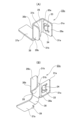
ピン受金具23は、ステンレス鋼板など1枚の金属板にプレス加工を施してなり、図20の(D)に示すように、全体が略J字状又は略U字状に構成されている。ピン受金具23の板厚Tは、挿通孔16aの内側にピン受金具23を取り付けた状態で、ピン11aが挿通孔16aの内側を軸方向に緩く挿通できる厚さに規制されている。また、本例では、ピン受金具23の一部(後述する折曲板部29b)が、裏板15aの表面(軸方向内側面)側に配置されるため、ピン受金具23の板厚Tは、摩擦材14aの許容限界厚さよりも小さい。
The pin receiving fitting 23 is formed by pressing a single metal plate such as a stainless steel plate, and has a generally J-shaped or generally U-shaped configuration as a whole, as shown in FIG. 20(D). The plate thickness T of the pin receiving fitting 23 is regulated to a thickness that allows the
ピン受金具23は、本体板部28と、1対の折曲板部29a、29bと、1対の湾曲部30a、30bとを有する。
The
本体板部28は、ピン11aの外周面と挿通孔16aの内周面との間に配置され、ピン11aの外周面と挿通孔16aの内周面とが衝突する際の衝撃を緩和する機能を有する。本体板部28は、平板状に構成されており、挿通孔16aの内周面のうちの径方向外側面のほぼ全体を覆っている。本体板部28に関して、裏板15aの板厚方向に沿って延びる方向(図20の(A)の表裏方向、図20の(B)及び(C)の上下方向、図20(D)の左右方向)のことを長さ方向といい、該長さ方向は、ディスクブレーキ装置1aの組立状態でロータ5の軸方向に一致する。また、本体板部28に関して、長さ方向及び厚さ方向にそれぞれ直交する方向(図20の(A)~(C)の左右方向、図20の(D)の表裏方向)のことを幅方向といい、該幅方向は、ディスクブレーキ装置1aの組立状態でロータ5の周方向に一致する。本体板部28の長さ寸法は、裏板15a(張出部26)の厚さ寸法とほぼ同じである。
The main
1対の折曲板部29a、29bは、ピン受金具23を裏板15aに固定する機能を有する。1対の折曲板部29a、29bは、本体板部28の長さ方向両側の端部に、本体板部28に対して略直角に折れ曲がるように備えられており、裏板15aに対し、該裏板15aの板厚方向に重なるように配置されている。1対の折曲板部29a、29bは、本体板部28の長さ方向両側の端部から、挿通孔16aの径方向に関して外側(本例ではロータ5の径方向に関して外側)に向けて伸長している。1対の折曲板部29a、29bは、互いに略平行に配置されており、裏板15aのうちで挿通孔16aの径方向外側近傍に存在する部分を、弾性的に挟持する。本例では、折曲板部29a、29bに関して、伸長方向(長さ方向)は、ディスクブレーキ装置1aの組立状態でロータ5の径方向に一致し、幅方向は、ディスクブレーキ装置1aの組立状態でロータ5の周方向に一致する。
The pair of
1対の折曲板部29a、29bの長さ寸法は、互いに異なる。具体的には、1対の折曲板部29a、29bのうち、軸方向外側(反ロータ側)に配置された一方の折曲板部29aの長さ寸法は、軸方向内側(ロータ側)に配置された他方の折曲板部29bの長さ寸法よりも大きい。
The length dimensions of the pair of
1対の折曲板部29a、29bのそれぞれの先端部(径方向外側の端部)には、幅方向両側部に、面取り部31a、31bが備えられている。このため、1対の折曲板部29a、29bの先端部は、先細形状を有する。図示の例では、一方の折曲板部29aには、面取り部31aとしてR面取りが採用されており、他方の折曲板部29bには、面取り部31bとしてC面取りが採用されているが、面取りの種類(形状)は特に問わない。
軸方向外側に配置された一方の折曲板部29aは、裏板15aと係合し、ピン受金具23が裏板15aから脱落するのを防止する機能をさらに備える。このために、一方の折曲板部29aは、抜け止め部を有する。これに対し、軸方向内側に配置された他方の折曲板部29bは、全体が平板状に構成されており、抜け止め部を有しない。
One of the
一方の折曲板部29aにのみ備えられた抜け止め部は、周囲を略U字状のスリット33により囲まれた、舌片34から構成されている。舌片34は、本体板部28に近い側の端部である径方向内側の端部が自由端であり、本体板部28から遠い側の端部である径方向外側の端部が結合端である。舌片34は、径方向内側に向かうほど、軸方向内側に向かう(裏板15aの裏面に近づく)方向に傾斜している。舌片34は、ピン受金具23を裏板15aに取り付けた状態で、軸方向外側に向けて弾性変形し、先端部(先端角部)が裏板15aの裏面に対して係合する。つまり、舌片34は、ピン受金具23が裏板15aに対して径方向内側に移動する際に、裏板15aの裏面に突っかかり(食い込み)、ピン受金具23が裏板15aに対して径方向内側に移動することを阻止する。本発明を実施する場合に、舌片の先端部を、裏板の裏面に形成した係合凹部に係合させることもできる。
The retaining portion provided only on one
1対の湾曲部30a、30bのそれぞれは、円弧状の断面形状を有し、全体が略四分の一円筒状に構成されている。1対の湾曲部30a、30bのそれぞれは、本体板部28と1対の折曲板部29a、29bのそれぞれとをつないでいる。1対の湾曲部30a、30bのそれぞれは、挿通孔16aの軸方向両側の開口縁部のうちの一辺(径方向外側辺)である、断面直角形状のエッジ部35a、35bを覆っている。
Each of the pair of
ピン受金具23は、次のような工程により取付作業を行うことができる。
先ず、本体板部28の長さ方向を裏板15aの板厚方向に一致させるとともに、1対の折曲板部29a、29bの先端部を、挿通孔16aの径方向に関して外側(本例ではロータ5の径方向外側)に向けた状態で、ピン受金具23を挿通孔16aの内側に配置する。
The
First, the length direction of the main
その後、本体板部28を挿通孔16aの内周面(径方向外側面)に対して近づけるようにピン受金具23を裏板15aに対して相対移動させることで、1対の折曲板部29a、29b同士の間に裏板15aを押し込む。これにより、一方の折曲板部29aのうちの舌片34と他方の折曲板部29bとの間で、裏板15aを弾性的に挟持する。この際、抜け止め部である舌片34は、弾性変形し、先端部が裏板15aの裏面に対して係合する。本例では、このようにしてピン受金具23を裏板15aに対して固定する。
Thereafter, by moving the
以上のような本例のディスクブレーキ装置1aによれば、制動解除時に、インナパッド3a及びアウタパッド4aのそれぞれの裏板15aに備えられた挿通孔16aの内周面と、挿通孔16aに挿通されたピン11aの外周面との衝突に基づく異音を、緩和することができる。
すなわち、本例では、インナパッド3a及びアウタパッド4aのそれぞれの裏板15aに備えられた挿通孔16aの内側に、ピン受金具23を取り付けており、ピン受金具23を構成する本体板部28によって、挿通孔16aの内周面のうちの径方向外側面を覆っている。このため、ピン11aの外周面の径方向外側の端部と挿通孔16aの内周面のうちの径方向外側面とが直接接触することを防止できる。制動解除時には、インナパッド3a及びアウタパッド4aに制動時に作用していたモーメント(トルク)M1、M2が作用しなくなり、裏板15aの周方向片側部は、パッドスプリング20aにより押圧されて、径方向内側に向けて移動する。この際、本例では、挿通孔16aの内周面のうちの径方向外側面を、本体板部28を介して、ピン11aの外周面の径方向外側の端部に衝突させることができる。このため、ピン11aの外周面と挿通孔16aの内周面との衝突に基づく異音を緩和することができる。
According to the
That is, in this example, the
また、1対の湾曲部30a、30bのそれぞれにより、挿通孔16aの開口縁部に存在するエッジ部35a、35bを覆うことができる。このため、エッジ部35a、35bとピン11aとが直接接触することを防止できる。したがって、エッジ部35a、35b及びピン11aに、応力集中に起因して、損傷が生じることを防止できる。また、制動時及び制動解除時に、ピン11aに対して、エッジ部35a、35bではなく、円弧状の断面形状を有する湾曲部30a、30bを摺動させられるため、ピン11aに対するインナパッド3a及びアウタパッド4aの摺動抵抗を低減できる。この結果、制動解除時に、摩擦材14aとロータ5との間のクリアランスを十分に確保することができ、引き摺り抵抗を低減できる。
Furthermore, the pair of
さらに、インナパッド3a及びアウタパッド4aのそれぞれにピン受金具23を取り付けることで、制動時におけるインナパッド3a及びアウタパッド4aのそれぞれの拘束条件を、ピン受金具23を取り付けない場合に対して変化させることができる。また、ピン11aに対して、挿通孔16aの内周面のうちの径方向外側面ではなく、本体板部28を接触させることができる。このため、制動時に、インナパッド3a及びアウタパッド4aに鳴きが発生することを抑制できる。
Furthermore, by attaching the
また、1対の折曲板部29a、29bの先端部を先細形状としているため、ピン受金具23をインナパッド3a及びアウタパッド4aに取り付ける際に、裏板15aが、1対の折曲板部29a、29b同士の間に引っ掛かることを防止できる。このため、ピン受金具23の取付作業の作業性を向上することができる。
Further, since the tips of the pair of
本例では、ピン受金具23を構成する1対の折曲板部29a、29bにより、裏板15aを弾性的に挟持することで、ピン受金具23を裏板15aに固定しており、ピン受金具23を固定するのに、ねじやリベットなどのその他の部品を用いたり、加工を施したりする必要がない。このため、ピン受金具23を裏板15aに固定するのに要するコストを低く抑えられる。
In this example, the
抜け止め部である舌片34の先端部(先端角部)を、裏板15aの裏面に係合させているため、ピン受金具23が裏板15aに対して径方向内側に移動するのを有効に阻止できる。したがって、ピン受金具23が裏板15aから脱落することを有効に防止できる。また、舌片34は、径方向内側の端部が自由端であり、径方向内側に向かうほど、軸方向内側に向かう方向に傾斜しているため、1対の折曲板部29a、29b同士の間に裏板15aを押し込むだけで、舌片34の先端部を裏板15aの裏面に係合させることができる。このため、ピン受金具23が裏板15aから脱落するのを防止するために、特別な加工を施さずに済む。したがって、この面からもコストを低く抑えることができる。
Since the tip (tip corner) of the
[実施の形態の第2例]
実施の形態の第2例について、図23を用いて説明する。
本例では、インナパッド3a(及びアウタパッド4a)の裏板15aに備えられた挿通孔16aに対するピン受金具23の取付位置を、実施の形態の第1例の構造から変更している。
[Second example of embodiment]
A second example of the embodiment will be described using FIG. 23.
In this example, the mounting position of the
本例では、本体板部28により、挿通孔16aの内周面のうちの周方向片側面(周方向に関して摩擦材14aとは反対側に位置する面)を覆うように、ピン受金具23を挿通孔16aの内側に取り付けている。このため、本体板部28は、ピン11a(図17等参照)の外周面の周方向片側の端部と挿通孔16aの内周面のうちの周方向片側面との間に介在する。1対の折曲板部29a、29bは、本体板部28の長さ方向に関して両側の端部から周方向片側に向けて伸長している。
In this example, the
以上のような本例では、前進制動時に、インナパッド3a及びアウタパッド4aのそれぞれが、周方向他側に向けて変位する際に、挿通孔16aの内周面のうちの周方向片側面を、本体板部28を介して、ピン11aの外周面の周方向片側の端部に衝突させることができるため、異音の発生を緩和することができる。
その他の構成及び作用効果については、実施の形態の第1例と同じである。
In this example as described above, when each of the
Other configurations and effects are the same as in the first example of the embodiment.
[実施の形態の第3例]
実施の形態の第3例について、図24を用いて説明する。
本例では、インナパッド3a(及びアウタパッド4a)の裏板15aに備えられた挿通孔16aに対する、ピン受金具23の取付数を、実施の形態の第1例及び第2例の構造から変更している。
[Third example of embodiment]
A third example of the embodiment will be described using FIG. 24.
In this example, the number of
実施の形態の第1例及び第2例では、挿通孔16aの内側にピン受金具23を1つだけ取り付けていたが、本例では、挿通孔16aの内側に、ピン受金具23を2つ取り付けている。第1のピン受金具23は、本体板部28によって挿通孔16aの内周面のうちの径方向外側面を覆うように、挿通孔16aの内側に取り付けられており、第2のピン受金具23は、本体板部28によって挿通孔16aの内周面のうちの周方向片側面を覆うように、挿通孔16aの内側に取り付けられている。要するに、本例は、実施の形態の第1例と第2例とを組み合わせたごとき構造を有する。
In the first and second embodiments, only one
以上のような本例によれば、制動解除時に、挿通孔16aの内周面のうちの径方向外側面を、第1のピン受金具23を構成する本体板部28を介して、ピン11a(図17等参照)の外周面の径方向外側の端部に衝突させることができる。また、前進制動時に、挿通孔16aの内周面のうちの周方向片側面を、第2のピン受金具23を構成する本体板部28を介して、ピン11aの外周面の周方向片側の端部に衝突(係合)させることができる。このため、制動解除時及び前進制動時のいずれの場合にも、異音の発生を緩和することができる。
その他の構成及び作用効果については、実施の形態の第1例及び第2例と同じである。
According to this example as described above, when the brake is released, the radially outer surface of the inner peripheral surface of the
The other configurations and effects are the same as the first and second examples of the embodiment.
[実施の形態の第4例]
実施の形態の第4例について、図25を用いて説明する。
本例では、ピン受金具23aを構成する本体板部28のうち、挿通孔16aの内周面と対向する面(図25の上面)が、ゴムや合成樹脂などの弾性部材36の薄膜により覆われている(コーティングされている)。なお、図25には、弾性部材36を斜格子模様で表している。これに対し、本体板部28のうち、ピン11a(図17等参照)と対向する面(図25の下面)は、弾性部材36により覆われていない。
[Fourth example of embodiment]
A fourth example of the embodiment will be described using FIG. 25.
In this example, the surface (top surface in FIG. 25) of the main
以上のような本例では、本体板部28のうち、挿通孔16aの内周面と対向する面が、弾性部材36により覆われているため、挿通孔16aの内周面とピン11aの外周面とが衝突する際の衝撃をより有効に緩和することができる。反対に、本体板部28のうち、ピン11aの外周面と対向する面は、弾性部材36により覆われていないため、ピン11aに対する摺動抵抗が大きくなることを防止できる。
In this example as described above, the surface of the main
なお、本発明を実施する場合に、図25に示したように、本体板部のうち、挿通孔の内周面に対向する面の全体を弾性部材によって覆うこともできるし、一部のみを弾性部材により覆うこともできる。また、挿通孔の内周面を弾性部材により覆うこともできるし、本体板部と挿通孔の内周面との間に、板状の弾性部材を挟持する構成を採用することもできる。
その他の作用効果については、実施の形態の第1例及び第2例と同じである。
In addition, when carrying out the present invention, as shown in FIG. 25, the entire surface of the main body plate facing the inner circumferential surface of the insertion hole may be covered with an elastic member, or only a portion may be covered with an elastic member. It can also be covered with an elastic member. Further, the inner peripheral surface of the insertion hole can be covered with an elastic member, or a configuration can be adopted in which a plate-shaped elastic member is sandwiched between the main body plate portion and the inner peripheral surface of the insertion hole.
Other effects are the same as in the first and second examples of the embodiment.
[実施の形態の第5例]
実施の形態の第5例について、図26~図28を用いて説明する。
本例は、実施の形態の第1例の変形例である。本例のピン受金具23bは、本体板部28と、1対の折曲板部29a、29bと、1対の湾曲部30a、30bとを備えるだけでなく、補助板部37と、屈曲部38とをさらに備える。
[Fifth example of embodiment]
A fifth example of the embodiment will be described using FIGS. 26 to 28.
This example is a modification of the first example of the embodiment. The
補助板部37は、平板状に構成されており、本体板部28の幅方向一方側(本例で周方向片側)の端部に備えられている。補助板部37は、本体板部28に対して直角に折れ曲がり、径方向内側に向けて伸長している。このような補助板部37は、挿通孔16aの内周面のうちの周方向片側面を覆っている。補助板部37のうち、挿通孔16aの内周面に対向する面は、前述した実施の形態の第4例で説明したような弾性部材により覆うこともできる。
The
補助板部37は、挿通孔16aの内側にピン11aを挿通する作業を行いやすくするためのガイド部39を有する。ガイド部39は、補助板部37のうち、ロータ5から遠い側の端部である軸方向外側の端部に備えられており、挿通孔16aの外側(軸方向外側)に突出して配置されている。ガイド部39は、平板状に構成されており、補助板部37のうち、ガイド部39以外の部分(挿通孔16aの内側に配置された部分)と同一平面上に配置されている。ただし、本発明を実施する場合には、ガイド部を、補助板部のうち、ガイド部以外の部分に対して傾斜させても良い。この場合には、ガイド部を、軸方向外側に向かうほど周方向片側に向かう方向に傾斜させることができる。
The
屈曲部38は、円弧状の断面形状を有し、全体が略四分の一円筒状に構成されている。屈曲部38は、本体板部28と補助板部37とをつないでいる。屈曲部38は、挿通孔16aの内周面のうち、径方向外側かつ周方向片側に存在する隅角部を覆っている。
The
以上のような本例では、制動解除時に、挿通孔16aの内周面のうちの径方向外側面を、本体板部28を介して、ピン11a(図17等参照)の外周面の径方向外側の端部に衝突させることができる。また、前進制動時に、挿通孔16aの内周面のうちの周方向片側面を、補助板部37を介して、ピン11aの外周面の周方向片側の端部に衝突させることができる。このため、制動解除時及び前進制動時のいずれの場合にも、異音の発生を緩和することができる。
In this example as described above, when the brake is released, the radially outer surface of the inner circumferential surface of the
上記したような作用効果を得るために、前述した実施の形態の第3例の構造においては、2つのピン受金具が必要であったのに対し、本例では、1つのピン受金具23bのみで足りる。このため、部品点数を低減することが可能になり、コスト低減を図ることができるとともに、取付作業工数を低減することもできる。また、本例においては、1つのピン受金具23bを取り付けるだけでよいため、2つのピン受金具を取り付ける場合のように、一方のピン受金具の取り付け作業を忘れてしまうといった不都合が生じることがない。また、補助板部37にガイド部39を備えているため、ピン11aを挿通孔16aの内側に挿通する作業を容易に行うことができる。
その他の構成及び作用効果については、実施の形態の第1例と同じである。
In order to obtain the above-mentioned effects, two pin holders were required in the structure of the third example of the embodiment described above, whereas in this example, only one
Other configurations and effects are the same as in the first example of the embodiment.
[実施の形態の第6例]
実施の形態の第6例について、図29を用いて説明する。
本例では、インナパッド3a(及びアウタパッド4a)の裏板15aに備えられた挿通孔16aに対するピン受金具23bの取付位置を、実施の形態の第5例の構造から変更している。
[Sixth example of embodiment]
A sixth example of the embodiment will be described using FIG. 29.
In this example, the mounting position of the
すなわち、本例では、本体板部28により、挿通孔16aの内周面のうちの周方向片側面(ロータ5の周方向に関して摩擦材14aとは反対側に位置する面)を覆うとともに、補助板部37により、挿通孔16aの内周面のうちの径方向外側面を覆うように、ピン受金具23bを挿通孔16aの内側に取り付けている。
That is, in this example, the main
このため、本体板部28は、ピン11a(図17等参照)の外周面の周方向片側の端部と挿通孔16aの内周面のうちの周方向片側面との間に介在し、補助板部37は、ピン11aの外周面の径方向外側の端部と挿通孔16aの内周面のうちの径方向外側面との間に介在する。また、1対の折曲板部29a、29bは、本体板部28の長さ方向に関して両側の端部から周方向片側に向けて伸長している。
Therefore, the main
以上のような本例では、前進制動時に、インナパッド3a及びアウタパッド4aのそれぞれが、周方向他側に向けて変位する際に、挿通孔16aの内周面のうちの周方向片側面を、本体板部28を介して、ピン11aの外周面の周方向片側の端部に衝突(係合)させることができる。また、制動解除時に、挿通孔16aの内周面のうちの径方向外側面を、補助板部37を介して、ピン11aの外周面の径方向外側の端部に衝突させることができる。このため、前進制動時及び制動解除時のいずれの場合にも、異音の発生を緩和することができる。
その他の構成及び作用効果については、実施の形態の第5例と同じである。
In this example as described above, when each of the
Other configurations and effects are the same as in the fifth example of the embodiment.
[実施の形態の第7例]
実施の形態の第7例について、図30を用いて説明する。
本例は、実施の形態の第5例の変形例である。本例のピン受金具23cでは、補助板部37aが、ピン11a(図17等参照)に対して弾性力を付与する機能を備える。このために、補助板部37aの自由状態で、本体板部28と補助板部37aとの間の挟角の大きさを、直角(90度)よりも少しだけ小さい鋭角としている。また、補助板部37aと挿通孔16aの内周面のうちの周方向片側面との間に、軸方向視で略三角形状の隙間を形成している。
[Seventh example of embodiment]
A seventh example of the embodiment will be described using FIG. 30.
This example is a modification of the fifth example of the embodiment. In the pin receiving fitting 23c of this example, the
補助板部37aは、挿通孔16aの内側にピン11aを挿通した際に、ピン11aとの当接により、本体板部28との間の挟角を大きくする(挿通孔16aの周方向片側面に近づく)ように弾性変形する。これにより、補助板部37aは、ピン11aに対し、周方向他側を向いた弾性力を付与する。
When the
以上のような本例では、補助板部37aにより、ピン11aを周方向他側に向けて押圧することができる。このため、ピン11aの外周面と挿通孔16aの内周面との間のがたつきを抑えることができる。つまり、ピン11aに対して、インナパッド3a及びアウタパッド4aが周方向にがたつくことを抑制できる。
その他の作用効果については、実施の形態の第5例と同じである。
In this example as described above, the
Other effects are the same as in the fifth example of the embodiment.
[実施の形態の第8例]
実施の形態の第8例について、図31~図33を用いて説明する。
本例では、インナパッド3a(及びアウタパッド4a)の裏板15aに備えられた挿通孔16aに対するピン受金具23cの取付位置を、実施の形態の第7例の構造から変更している。なお、本例のピン受金具23cと、実施の形態の第7例のピン受金具23cとは、たとえば面取り部31bなどの細部の形状が異なるが、基本的な形状は同じであるため、形状の相違に関する説明は省略する。
[Eighth example of embodiment]
An eighth example of the embodiment will be described using FIGS. 31 to 33.
In this example, the mounting position of the
本例では、本体板部28により、挿通孔16aの内周面のうちの周方向片側面を覆うとともに、補助板部37aにより、挿通孔16aの内周面のうちの径方向内側面を覆うように、ピン受金具23cを挿通孔16aの内側に取り付けている。補助板部37aは、ピン11a(図17等参照)に対し、径方向外側を向いた弾性力を付与する。
In this example, the main
以上のような本例では、補助板部37aにより、ピン11aを径方向外側に向けて押圧することができる。このため、裏板15aの外周縁部を径方向内側に向けて押圧するパッドスプリング20aの押圧力と相まって、インナパッド3a及びアウタパッド4aの周方向片側部が、径方向外側に変位する(浮き上がる)ことを抑制できる。
その他の構成及び作用効果については、実施の形態の第7例と同じである。
In this example as described above, the
Other configurations and effects are the same as in the seventh example of the embodiment.
[実施の形態の第9例]
実施の形態の第9例について、図34を用いて説明する。
本例では、インナパッド3a(及びアウタパッド4a)の裏板15aに備えられた挿通孔16aに対するピン受金具23cの取付位置を、実施の形態の第7例及び第8例の構造から変更している。
[Ninth example of embodiment]
A ninth example of the embodiment will be described using FIG. 34.
In this example, the mounting position of the
本例では、本体板部28により、挿通孔16aの内周面のうちの周方向片側面を覆うとともに、補助板部37aにより、挿通孔16aの内周面のうちの径方向外側面を覆うように、ピン受金具23cを挿通孔16aの内側に取り付けている。補助板部37aは、ピン11a(図17等参照)に対し、径方向内側を向いた弾性力を付与する。
In this example, the main
以上のような本例では、補助板部37aにより、ピン11aを径方向内側に向けて押圧することができる。このため、ピン11aの外周面と挿通孔16aの内周面との間のがたつきを抑制することができる。つまり、ピン11aに対して、インナパッド3a及びアウタパッド4aの周方向片側部が、それぞれが径方向にがたつくことを抑制できる。
その他の構成及び作用効果については、実施の形態の第7例と同じである。
In this example as described above, the
Other configurations and effects are the same as in the seventh example of the embodiment.
[実施の形態の第10例]
実施の形態の第10例について、図35~図37を用いて説明する。
本例は、実施の形態の第1例の変形例である。本例のピン受金具23dは、1対の折曲板部29a、29bのうち、軸方向外側の折曲板部29aの形状が、平板状ではなく、径方向(伸長方向)中間部を頂部40aとして、全体が略V字状に屈曲した形状を有している。具体的には、軸方向外側に配置された一方の折曲板部29aは、基端側半部が、径方向外側に向かうほど軸方向内側に向かう方向に傾斜しており、先端側半部が、径方向外側に向かうほど軸方向外側に向かう方向に傾斜している。
[10th example of embodiment]
A tenth example of the embodiment will be described using FIGS. 35 to 37.
This example is a modification of the first example of the embodiment. In the pin receiving fitting 23d of this example, the shape of the axially outer
本例では、軸方向外側に配置された折曲板部29aの径方向中間部に備えられた頂部40aを、抜け止め部として機能させている。つまり、頂部40aを、裏板15aの裏面に対して係合させている(突き当てている)。
In this example, the
以上のような本例では、折曲板部29aに抜け止め部を備えるために、ピン受金具23dを構成する金属板に、打ち抜き加工を施す必要がなく、曲げ加工を施すのみで足りる。このため、加工コストの低減を図れる。
その他の構成及び作用効果については、実施の形態の第1例と同じである。
In this example as described above, since the bending
Other configurations and effects are the same as in the first example of the embodiment.
[参考例の第1例]
参考例の第1例について、図38~図39を用いて説明する。
本参考例は、実施の形態の第10例の変形例である。本参考例のピン受金具23eは、1対の折曲板部29a、29bのそれぞれの形状を、平板状ではなく、径方向(伸長方向)中間部を頂部40a、40bとして、全体が略V字状に屈曲した形状としている。すなわち、本参考例のピン受金具23eは、本体板部28の長さ方向に関して対称な形状を有する。
[ First reference example ]
A first reference example will be described using FIGS. 38 to 39.
This reference example is a modification of the tenth example of the embodiment. In the pin receiving fitting 23e of this reference example, the shape of each of the pair of
具体的には、軸方向外側に配置された一方の折曲板部29aは、基端側半部が、径方向外側に向かうほど軸方向内側に向かう方向に傾斜しており、先端側半部が、径方向外側に向かうほど軸方向外側に向かう方向に傾斜している。また、軸方向内側に配置された他方の折曲板部29bは、基端側半部が、径方向外側に向かうほど軸方向外側に向かう方向に傾斜しており、先端側半部が、径方向外側に向かうほど軸方向内側に向かう方向に傾斜している。したがって、1対の折曲板部29a、29bは、頂部40a、40bにおいて、互いの離間寸法(軸方向寸法)が最も小さくなっており、頂部40a、40bから径方向に離れるほど、離間寸法が次第に大きくなる。
Specifically, one
本参考例では、1対の折曲板部29a、29bの径方向中間部に備えられた頂部40a、40bのそれぞれを、抜け止め部としている。つまり、一方の折曲板部29aに備えられた頂部40aを、裏板15aの裏面に係合させており、他方の折曲板部29bに備えられた頂部40bを、裏板15aの表面に係合させている。
In this reference example,
以上のような本参考例の場合にも、1対の折曲板部29a、29bのそれぞれに抜け止め部を備えるために、ピン受金具23eを構成する金属板に、打ち抜き加工を施す必要がなく、曲げ加工を施すのみで足りる。このため、加工コストの低減を図れる。また、1対の折曲板部29a、29bの離間寸法を、先端部で大きくすることができるため、1対の折曲板部29a、29b同士の間に裏板15aを押し込む作業を行いやすくすることができる。また、本参考例のピン受金具23eは、本体板部28の長さ方向に関して対称な形状を有するため、ピン受金具23eを取り付ける際に、取付方向に注意を払う必要がなく、作業性を向上することができる。
その他の構成及び作用効果については、実施の形態の第1例と同じである。
Also in the case of this reference example as described above, it is necessary to perform punching on the metal plate constituting the pin receiving fitting 23e in order to provide a retaining portion in each of the pair of
Other configurations and effects are the same as in the first example of the embodiment.
[参考例の第2例]
参考例の第2例について、図40及び図41を用いて説明する。
本参考例は、参考例の第1例の変形例である。本参考例では、ピン受金具23eを取り付ける、裏板15bの形状を工夫している。
[ Second reference example ]
A second example of the reference example will be described using FIGS. 40 and 41.
This reference example is a modification of the first reference example . In this reference example, the shape of the
裏板15bの表面及び裏面のそれぞれには、挿通孔16aの径方向外側近傍に、周方向に伸長した直線状の係合凹部(凹溝)41a、41bが備えられている。係合凹部41a、41bのそれぞれは、略三角状の断面形状を有している。係合凹部41a、41bのそれぞれの底面は、径方向内側に配置された第1の傾斜面部42と、径方向外側に配置された第2の傾斜面部43とから構成されている。
On each of the front and back surfaces of the
第1の傾斜面部42は、裏板15bの板厚方向に関して係合凹部41a、41bの奥側に向かうほど、径方向(折曲板部29a、29bの伸長方向)に関して本体板部28から離れる方向(径方向外側)に傾斜している。第2の傾斜面部43は、裏板15bの板厚方向に関して係合凹部41a、41bの奥側に向かうほど、径方向(折曲板部29a、29bの伸長方向)に関して本体板部28に近づく方向(径方向内側)に傾斜している。このため、係合凹部41a、41bのそれぞれの底面は、V字形に屈曲している。
The first
1対の折曲板部29a、29bにより裏板15bを挟持した状態で、折曲板部29a、29bに備えられた、抜け止め部である頂部40a、40bは、係合凹部41a、41bに対して係合する。具体的には、頂部40a、40bのそれぞれは、係合凹部41a、41bの内側に進入し、少なくとも第1の傾斜面部42に対して係合する。このため、頂部40a、40b(折曲板部29a、29b)には、第1の傾斜面部42との係合により径方向外側を向いた力が作用する。本参考例では、このような力を利用して、本体板部28を挿通孔16aの内周面のうちの径方向外側面に対して押し付けている。
With the
以上のような本参考例では、抜け止め部である頂部40a、40bと係合凹部41a、41bとの係合により、ピン受金具23eに対して径方向外側に向いた力を作用させられるため、ピン受金具23eが裏板15bから脱落する(径方向内側に移動する)ことを、より有効に防止することができる。
その他の構成及び作用効果については、参考例の第1例と同じである。
In this reference example as described above, a force directed outward in the radial direction is applied to the pin receiving fitting 23e due to the engagement between the
The other configurations and effects are the same as those in the first reference example .
[参考例の第3例]
参考例の第3例について、図42~図45を用いて説明する。
本参考例のピン受金具23fは、本体板部28と、1つの折曲板部29bと、1つの湾曲部30bとから構成されている。折曲板部29bは、本体板部28の軸方向内側の端部に備えられている。
[ Third reference example ]
A third reference example will be described using FIGS. 42 to 45.
The pin receiving fitting 23f of this reference example includes a main
本参考例では、上述のようなピン受金具23fを、裏板15aに対して、接着材を利用して接着固定している。具体的には、本体板部28を、挿通孔16aの内周面のうちの径方向外側面に対して接着固定している。
In this reference example, the pin receiving fitting 23f as described above is adhesively fixed to the
以上のような本参考例では、ピン受金具23fを、本体板部28と1つの折曲板部29bと1つの湾曲部30bとから構成しているため、ピン受金具23fの小型化及び軽量化を図ることができる。また、ピン受金具23fを裏板15aに対して接着固定しているため、ピン受金具23fを固定する際に、大きな力が不要になる。また、本参考例では、1つの折曲板部29bを、本体板部28の軸方向内側の端部にのみ備えている。このため、制動時に、ピン11a(図17等参照)と摺接によりピン受金具23f(本体板部28)に作用する力を、折曲板部29bと裏板15aの表面との係合によって支承することもできる。したがって、ピン受金具23fが裏板15aから脱落することを有効に防止できる。また、折曲板部29bを裏板15aの表面に対して当接させることで、裏板15aに対するピン受金具23fの軸方向に関する位置決めを図ることもできる。
その他の作用効果については、実施の形態の第1例と同じである。
In this reference example as described above, the
Other effects are the same as in the first example of the embodiment.
[参考例の第4例]
参考例の第4例について、図46~図49を用いて説明する。
本参考例は、実施の形態の第1例の変形例である。本参考例のピン受金具23gは、本体板部28と、1つの折曲板部29aと、1つの湾曲部30aとから構成されている。折曲板部29aは、本体板部28の軸方向外側の端部に備えられており、抜け止め部を備えている。本例では、抜け止め部を、折曲板部29aを板厚方向(軸方向)に貫通する、係合孔44から構成している。
[ Fourth reference example ]
A fourth reference example will be described using FIGS. 46 to 49.
This reference example is a modification of the first example of the embodiment. The
インナパッド3a及びアウタパッド4aのそれぞれの裏板15cの裏面には、挿通孔16aの径方向外側近傍に、軸方向外側に向けて突出した円柱状の係合凸部45が備えられている。係合凸部45の外径は、係合孔44の内径と同じか又は係合孔44の内径よりもわずかに小さい。
On the back surface of the
本参考例では、係合孔44の内側に係合凸部45を嵌合(がたつきなく挿通)させている。さらに、係合凸部45の先端部をかしめて(塑性変形させて)、係合凸部45の先端部にかしめ部46を形成している。
In this reference example, the
以上のような本参考例では、裏板15cからピン受金具23gが脱落する(径方向内側に移動する)ことを、より有効に阻止することができる。なお、本発明を実施する場合には、係合凸部45の先端部からかしめ部46を省略する、つまり、係合孔44の内側に係合凸部45を嵌合のみさせる構造を採用することもできる。
その他の構成及び作用効果については、実施の形態の第1例と同じである。
In this reference example as described above, it is possible to more effectively prevent the
Other configurations and effects are the same as in the first example of the embodiment.
[参考例の第5例]
参考例の第5例について、図50~図52を用いて説明する。
本参考例のピン受金具23hは、参考例の第4例のピン受金具23gと同様に、本体板部28と、1つの折曲板部29aと、1つの湾曲部30aとを備えている。特に本参考例のピン受金具23hは、軸方向外側に配置された一方の折曲板部29aが、裏板15dの裏面に重ね合わされるシム板部47を一体に備えている。
[ Fifth reference example ]
A fifth reference example will be explained using FIGS. 50 to 52.
The
シム板部47は、平板状に構成されており、制動時に、裏板15dの裏面とインナピストン(又はアウタピストン)との間に挟持される。シム板部47は、制動時にインナパッド3a(アウタパッド4a)が振動することにより発生するブレーキ鳴きを抑制したり、摩擦材14aの偏摩耗を抑制したりする機能を有する。
The
シム板部47は、外周寄り部分の複数箇所に、周方向に伸長した長孔48を備える。長孔48のそれぞれには、裏板15dの裏面に立設された突起部49が、周方向に関する相対変位を可能に、かつ、軸方向に関する相対変位を不能に係合している。このため、シム板部47は、裏板15dの裏面から軸方向に脱落不能に支持されている。本参考例では、このようなシム板部47を、折曲板部29aと一体に備えているため、ピン受金具23hは、接着材やかしめなどの固定手段によっては、裏板15dに固定されていない。
The
以上のような本参考例では、折曲板部29aと一体に備えられたシム板部47を利用して、ピン受金具23hを裏板15dに固定できるため、ピン受金具とシム板とを別々に設けた場合に比べて、部品点数の低減を図れるとともに、固定作業の作業工数を低減することができる。
その他の構成及び作用効果については、実施の形態の第1例と同じである。
In this reference example as described above, the
Other configurations and effects are the same as in the first example of the embodiment.
[実施の形態の第11例]
実施の形態の第11例について、図53を用いて説明する。
本例では、インナパッド3a及びアウタパッド4aのそれぞれの裏板15aに備えられた挿通孔16bの形状を、実施の形態の第1例~第10例及び参考例の第1例~第5例の構造とは異ならせている。
[ Eleventh example of embodiment]
An eleventh example of the embodiment will be described using FIG. 53.
In this example, the shape of the
本例の場合にも、挿通孔16bの内周面を、それぞれが平坦面である4つの側面S1~S4(径方向外側面S1、径方向内側面S2、周方向片側面S3及び周方向他側面S4)と、それぞれが凹曲面である4つの隅角部C1~C4とから構成している。特に本例では、径方向外側かつ周方向片側に存在する隅角部C1の曲率半径を、その他の隅角部C2~C4の曲率半径よりも十分に大きく、かつ、挿通孔16bの内側に挿通されるピン11a(図17等参照)の曲率半径よりも大きくしている。なお、挿通孔16bの内周面のうちの隅角部C1を、ピン受金具の本体板部により覆う構成を採用する場合には、本体板部を、平板状ではなく、部分円筒状に構成する。
In the case of this example as well, the inner circumferential surface of the
以上のような本例では、ピン11aの外周面と挿通孔16bの内周面との接触面積を大きくすることができる。このため、異音の発生を抑制することができる。
その他の構成及び作用効果については、実施の形態の第1例と同じである。
In this example as described above, the contact area between the outer peripheral surface of the
Other configurations and effects are the same as in the first example of the embodiment.
[参考例の第6例]
参考例の第6例について、図54を用いて説明する。
本参考例では、インナパッド3a及びアウタパッド4aのそれぞれの裏板15aに備えられた挿通孔16cの形状を、実施の形態の第1例~第11例及び参考例の第1例~第5例の構造とは異ならせている。
[ 6th reference example ]
A sixth reference example will be described using FIG. 54.
In this reference example, the shapes of the
本参考例の場合には、実施の形態の第11例にかかる挿通孔16bを構成する隅R部C1の曲率半径をさらに大きくし(2つの側面S1、S3を省略し)、挿通孔16cを、軸方向視で略三角形状(扇形状)または略1/4円形状に構成している。挿通孔16cの内周面は、それぞれが平坦面である2つの側面S2、S4(径方向内側面S2及び周方向他側面S4)と、凹曲面である1つの側面S5と、それぞれが凹曲面である3つの隅角部C2~C4とから構成している。なお、挿通孔16cの内周面のうちの側面S5を、ピン受金具の本体板部により覆う構成を採用する場合には、本体板部を、平板状ではなく、部分円筒状に構成する。
In the case of this reference example, the radius of curvature of the corner R portion C1 constituting the
以上のような本参考例の場合にも、ピン11aの外周面と挿通孔16cの内周面との接触面積を大きくすることができる。このため、異音の発生を抑制することができる。また、ピン11aの外周面と挿通孔16cの内周面との間の隙間をより小さくすることができるため、インナパッド3a及びアウタパッド4aのがたつきを抑制することができる。
その他の構成及び作用効果については、実施の形態の第1例と同じである。
Also in the case of this reference example as described above, the contact area between the outer circumferential surface of the
Other configurations and effects are the same as in the first example of the embodiment.
[実施の形態の第12例]
実施の形態の第12例について、図55を用いて説明する。
本例では、インナパッド3a(及びアウタパッド4a)の裏板15aに備えられたピン挿通部を、裏板15aの軸方向両側にのみ開口した挿通孔ではなく、周方向片側にも開口した切り欠き50により構成している。
[ Twelfth example of embodiment]
A twelfth example of the embodiment will be described using FIG. 55.
In this example, the pin insertion portion provided in the
切り欠き50は、軸方向視で、略矩形状に構成されている。切り欠き50の内周面は、それぞれが平坦面である3つの側面S1、S2、S4(径方向外側面S1、径方向内側面S2及び周方向他側面S4)と、それぞれが凹曲面である2つの隅角部C2、C3とから構成している。なお、本例の構造では、前進制動時に、インナパッド3a(アウタパッド4a)に作用する周方向他側(図55の左側、回出側)を向いたブレーキ接線力は、裏板15aの周方向他側面とガイド壁部13a(図9等参照)との当接により支承する。
The
以上のような本例では、ピン挿通部を、挿通孔ではなく切り欠き50としているため、ピン挿通部の加工コストを低く抑えられるとともに、インナパッド3a(及びアウタパッド4a)の軽量化を図れる。
その他の構成及び作用効果については、実施の形態の第1例と同じである。
In this example as described above, since the pin insertion portion is formed as a
Other configurations and effects are the same as in the first example of the embodiment.
[実施の形態の第13例]
実施の形態の第13例について、図56を用いて説明する。
本例では、キャリパ2a(図1等参照)に対するインナパッド3a(及びアウタパッド4a)の支持構造を変更している。具体的には、本例では、ディスクブレーキ装置1a全体で、ピン11a(図17等参照)を合計4本備えている。そして、インナパッド3a(及びアウタパッド4a)の周方向両側部を、キャリパ2aに支持された1対のピン11aに対して軸方向に移動可能に係合させている。このため、インナパッド3a(及びアウタパッド4a)のそれぞれの裏板15eは、周方向両側部に、挿通孔16aを有する張出部26を備えている。
[ 13th example of embodiment]
A thirteenth example of the embodiment will be described using FIG. 56.
In this example, the support structure of the
本例の場合には、周方向片側に配置された挿通孔16aだけでなく、周方向他側に配置された挿通孔16aの内側にも、ピン受金具23を取り付けることができる。このため、周方向片側に配置された挿通孔16aの内周面とピン11aの外周面との衝突に基づく異音を抑制できるだけでなく、周方向他側に配置された挿通孔16aの内周面とピン11aの外周面との衝突に基づく異音を抑制することができる。
その他の構成及び作用効果については、実施の形態の第1例と同じである。
In the case of this example, the
Other configurations and effects are the same as in the first example of the embodiment.
実施の形態の各例の構造及び参考例の各例の構造は、矛盾を生じない限りにおいて、適宜組み合わせて実施することができる。 The structure of each example of the embodiment and the structure of each example of the reference example can be appropriately combined and implemented as long as no contradiction occurs.
本発明のピン受金具は、実施の形態の各例及び参考例の各例で説明した構造に限定されず、ピンとピン挿通部との間で発生する異音を抑制できる限り、適宜形状を変更することができる。また、ピン受金具の取付位置及び取付数についても、実施の形態の各例及び参考例の各例で示した構造に限定されない。ピン受金具が取り付けられるピン挿通部(挿通孔及び切り欠き)の形状についても、実施の形態の各例及び参考例の各例で説明した形状に限定されない。また、ディスクブレーキ装置の周方向他側部分における、パッド支持部材に対するパッドの支持構造についても、実施の形態の各例及び参考例の各例で説明した構造に限定されない。 The pin holder of the present invention is not limited to the structure described in each of the embodiments and reference examples , and the shape can be changed as appropriate as long as abnormal noise generated between the pin and the pin insertion part can be suppressed. can do. Further, the mounting position and number of pin holders are not limited to the structures shown in each example of the embodiment and each example of the reference example . The shape of the pin insertion portion (insertion hole and notch) to which the pin receiver is attached is also not limited to the shape described in each example of the embodiment and each example of the reference example . Further, the support structure of the pad with respect to the pad support member on the other side in the circumferential direction of the disc brake device is not limited to the structure described in each example of the embodiment and each example of the reference example .
1、1a ディスクブレーキ装置
2、2a キャリパ
3、3a インナパッド
4、4a アウタパッド
5 ロータ
6、6a インナボディ
7、7a アウタボディ
8、8a 回入側連結部
9、9a 回出側連結部
10、10a センターブリッジ
11、11a ピン
12、12a ガイド凹溝
13、13a ガイド壁部
14、14a 摩擦材
15、15a~15e 裏板
16、16a~16c 挿通孔
17、17a 耳部
18、18a 被突き当て面
19、19a 突き当て面
20、20a、20b パッドスプリング
21a~21d 回入側押圧部
22a~22d 回出側押圧部
23、23a~23h ピン受金具
24 アウタシリンダ
25 取付座
26 張出部
27 凹部
28 本体板部
29a、29b 折曲板部
30a、30b 湾曲部
31a、31b 面取り部
33 スリット
34 舌片
35a、35b エッジ部
36 弾性部材
37、37a 補助板部
38 屈曲部
39 ガイド部
40a、40b 頂部
41a、41b 係合凹部
42 第1の傾斜面部
43 第2の傾斜面部
44 係合孔
45 係合凸部
46 かしめ部
47 シム板部
48 長孔
49 突起部
50 切り欠き
1, 1a
Claims (19)
前記ピン挿通部の内側に取り付けられたピン受金具と、を備え、
前記ピン挿通部は、軸方向視で略矩形状の挿通孔又は切り欠きであり、内周面に平坦面である側面を有しており、
前記ピン受金具は、ステンレス鋼板製で、前記ピン挿通部の内周面を覆う平板状の本体板部と、前記裏板の板厚方向に延びる前記本体板部の長さ方向に関して両側の端部に備えられ、かつ、前記裏板を板厚方向に弾性的に挟持する1対の折曲板部とを有し、
前記本体板部は、前記ピン挿通部の内周面を構成する1つの前記側面のほぼ全体を覆っており、
前記1対の折曲板部のうちで、前記裏板の表面側に配置された一方の折曲板部は、先細形状を有しており、前記裏板の裏面側に配置された他方の折曲板部よりも長さ寸法が短く、かつ、前記本体板部よりも長さ寸法が短い、
ピン受金具付きディスクブレーキ用パッド。 A disc brake pad having a back plate having a pin insertion portion that is inserted into the inner side and has a cylindrical outer peripheral surface shape that engages during braking, and a friction material supported on the surface of the back plate ;
a pin receiving fitting attached to the inside of the pin insertion part,
The pin insertion portion is a substantially rectangular insertion hole or notch when viewed in the axial direction, and has a flat side surface on the inner peripheral surface,
The pin receiving fitting is made of stainless steel plate, and includes a flat body plate portion that covers the inner peripheral surface of the pin insertion portion, and ends on both sides in the length direction of the body plate portion extending in the thickness direction of the back plate. a pair of bent plate parts that are provided in the part and elastically sandwich the back plate in the thickness direction;
The main body plate portion covers almost the entirety of one of the side surfaces constituting the inner circumferential surface of the pin insertion portion,
Of the pair of bent plate parts, one bent plate part placed on the front side of the back plate has a tapered shape, and the other bent plate part placed on the back side of the back plate has a tapered shape. The length is shorter than the bent plate part, and the length is shorter than the main body plate part.
Disc brake pad with pin holder.
前記抜け止め部は、前記頂部により構成され、前記裏板のうちで、前記ピン挿通部の近傍に形成された係合凹部と係合する、
請求項3~4のうちのいずれか1項に記載したピン受金具付きディスクブレーキ用パッド。 The bent plate portion has a shape that is bent in a substantially V-shape as a whole with the middle portion in the extension direction as the top portion,
The retaining portion is configured by the top portion and engages with an engaging recess formed in the back plate near the pin insertion portion.
A disc brake pad with a pin holder according to any one of claims 3 to 4 .
前記抜け止め部である前記舌片又は前記頂部は、前記傾斜面部に対して係合することで、前記本体板部を前記ピン挿通部の内周面に対して押し付ける、
請求項5~7のうちのいずれか1項に記載したピン受金具付きディスクブレーキ用パッド。 The bottom surface of the engagement recess has an inclined surface part that is inclined in a direction away from the main body plate part with respect to the extension direction of the bending plate part as it goes to the back of the engagement recess in the thickness direction of the back plate. and
The tongue piece or the top portion serving as the slip-off prevention portion presses the main body plate portion against the inner circumferential surface of the pin insertion portion by engaging with the inclined surface portion.
A disc brake pad with a pin holder according to any one of claims 5 to 7 .
請求項3~4のうちのいずれか1項に記載したピン受金具付きディスクブレーキ用パッド。 The retaining portion is constituted by an engagement hole formed in the bent plate portion , into which an engagement convex portion formed in the vicinity of the pin insertion portion of the back plate is fitted.
A disc brake pad with a pin holder according to any one of claims 3 to 4 .
前記ロータの中心軸と平行に配置された少なくとも1対のピンを有し、前記1対のディスクブレーキ用パッドを軸方向に移動可能に支持するパッド支持部材と、
を備えたディスクブレーキ装置であって、
前記1対のディスクブレーキ用パッドのうち少なくとも一方が、請求項1~18のうちのいずれか1項に記載したピン受金具付きディスクブレーキ用パットである、
ディスクブレーキ装置。 A pair of disc brake pads placed across the rotor,
a pad support member having at least one pair of pins arranged parallel to the central axis of the rotor, and supporting the pair of disc brake pads movably in the axial direction;
A disc brake device comprising:
At least one of the pair of disc brake pads is a disc brake pad with a pin holder according to any one of claims 1 to 18 .
Disc brake device.
Priority Applications (4)
| Application Number | Priority Date | Filing Date | Title |
|---|---|---|---|
| JP2020004654A JP7426245B2 (en) | 2020-01-15 | 2020-01-15 | Disc brake pad and disc brake device with pin holder |
| US17/149,198 US20210215212A1 (en) | 2020-01-15 | 2021-01-14 | Pad pin receiver, disc brake pad, and disc brake device |
| CN202110056334.0A CN113124073A (en) | 2020-01-15 | 2021-01-15 | Pin boss metal member for pad, pad for disc brake, and disc brake device |
| EP21151803.0A EP3851699B1 (en) | 2020-01-15 | 2021-01-15 | Disc brake pad and disc brake device |
Applications Claiming Priority (1)
| Application Number | Priority Date | Filing Date | Title |
|---|---|---|---|
| JP2020004654A JP7426245B2 (en) | 2020-01-15 | 2020-01-15 | Disc brake pad and disc brake device with pin holder |
Publications (3)
| Publication Number | Publication Date |
|---|---|
| JP2021110441A JP2021110441A (en) | 2021-08-02 |
| JP2021110441A5 JP2021110441A5 (en) | 2022-12-08 |
| JP7426245B2 true JP7426245B2 (en) | 2024-02-01 |
Family
ID=74186478
Family Applications (1)
| Application Number | Title | Priority Date | Filing Date |
|---|---|---|---|
| JP2020004654A Active JP7426245B2 (en) | 2020-01-15 | 2020-01-15 | Disc brake pad and disc brake device with pin holder |
Country Status (4)
| Country | Link |
|---|---|
| US (1) | US20210215212A1 (en) |
| EP (1) | EP3851699B1 (en) |
| JP (1) | JP7426245B2 (en) |
| CN (1) | CN113124073A (en) |
Families Citing this family (1)
| Publication number | Priority date | Publication date | Assignee | Title |
|---|---|---|---|---|
| WO2023040178A1 (en) * | 2021-09-18 | 2023-03-23 | 奥创动力传动(深圳)有限公司 | Friction disk and brake |
Citations (3)
| Publication number | Priority date | Publication date | Assignee | Title |
|---|---|---|---|---|
| JP2006520448A (en) | 2003-03-20 | 2006-09-07 | ルーカス・オートモーティブ・ゲーエムベーハー | Disc brake |
| JP2015090201A (en) | 2013-11-07 | 2015-05-11 | 曙ブレーキ工業株式会社 | Disk brake pad spring |
| JP2015203479A (en) | 2014-04-16 | 2015-11-16 | 株式会社アドヴィックス | Disc brake device |
Family Cites Families (18)
| Publication number | Priority date | Publication date | Assignee | Title |
|---|---|---|---|---|
| DE8023707U1 (en) * | 1980-09-05 | 1982-01-07 | Adam Opel AG, 6090 Rüsselsheim | PARTIAL DISC BRAKES |
| EP0157169A3 (en) * | 1984-04-04 | 1986-10-01 | Allied Corporation | Friction element anti-rattle spring |
| DE4110850A1 (en) * | 1991-04-04 | 1992-10-08 | Teves Gmbh Alfred | FLOATING SADDLE PARTIAL DISC BRAKE WITH ACTIVE RESETTING BRAKE SHOES |
| DE4237654A1 (en) * | 1992-04-01 | 1993-10-07 | Porsche Ag | Disc brake for a motor vehicle |
| JP3465339B2 (en) * | 1994-03-25 | 2003-11-10 | アイシン精機株式会社 | Mounting member for disc brake |
| JP3211662B2 (en) * | 1995-06-05 | 2001-09-25 | 住友電気工業株式会社 | Disc brake |
| JP2001304311A (en) * | 2000-04-27 | 2001-10-31 | Akebono Brake Ind Co Ltd | Floating caliper type disc brake |
| DE10312480B4 (en) * | 2003-03-20 | 2007-03-29 | Lucas Automotive Gmbh | Disc brake with brake pads guided on bolts |
| US7267208B2 (en) * | 2004-12-14 | 2007-09-11 | Akebono Corporation | Retention spring for brake pressure pads |
| JP2009156334A (en) * | 2007-12-26 | 2009-07-16 | Advics Co Ltd | Disk brake |
| DE102008058265A1 (en) * | 2008-11-20 | 2010-05-27 | Lucas Automotive Gmbh | Disc brake and brake pad assembly for this |
| DE102011112247B4 (en) * | 2011-09-01 | 2022-12-22 | Zf Active Safety Gmbh | Brake pad assembly for a vehicle brake |
| JP5855606B2 (en) * | 2013-06-18 | 2016-02-09 | 日信工業株式会社 | Vehicle disc brake |
| DE102013010876A1 (en) * | 2013-06-28 | 2014-12-31 | Lucas Automotive Gmbh | Brake pad arrangement for a disc brake with a device for noise reduction |
| CN106536961B (en) * | 2014-05-27 | 2019-01-29 | 福乐尼·乐姆宝公开有限公司 | The spring of the clamp of disk brake |
| WO2017059336A1 (en) * | 2015-10-01 | 2017-04-06 | Peformance Friction Corporation | Brake pad with spring clip for noise and vibration abatement |
| DE102016202520A1 (en) * | 2016-02-18 | 2017-08-24 | Continental Teves Ag & Co. Ohg | Friction lining arrangement with restoring spring for clearance simulation for a motor vehicle part lining disc brake |
| DE102017222639A1 (en) * | 2017-01-31 | 2018-08-02 | Continental Teves Ag & Co. Ohg | Fixed caliper motor vehicle tamper disc brake with a steel sheet bowing clearance spring |
-
2020
- 2020-01-15 JP JP2020004654A patent/JP7426245B2/en active Active
-
2021
- 2021-01-14 US US17/149,198 patent/US20210215212A1/en active Pending
- 2021-01-15 CN CN202110056334.0A patent/CN113124073A/en active Pending
- 2021-01-15 EP EP21151803.0A patent/EP3851699B1/en active Active
Patent Citations (3)
| Publication number | Priority date | Publication date | Assignee | Title |
|---|---|---|---|---|
| JP2006520448A (en) | 2003-03-20 | 2006-09-07 | ルーカス・オートモーティブ・ゲーエムベーハー | Disc brake |
| JP2015090201A (en) | 2013-11-07 | 2015-05-11 | 曙ブレーキ工業株式会社 | Disk brake pad spring |
| JP2015203479A (en) | 2014-04-16 | 2015-11-16 | 株式会社アドヴィックス | Disc brake device |
Also Published As
| Publication number | Publication date |
|---|---|
| EP3851699A1 (en) | 2021-07-21 |
| US20210215212A1 (en) | 2021-07-15 |
| JP2021110441A (en) | 2021-08-02 |
| CN113124073A (en) | 2021-07-16 |
| EP3851699B1 (en) | 2023-10-18 |
Similar Documents
| Publication | Publication Date | Title |
|---|---|---|
| US4940119A (en) | Disc brake assembly | |
| JP4039753B2 (en) | Disc brake | |
| US5464077A (en) | Floating-caliper spot-type disc brake for high-powered vehicles | |
| JP6261289B2 (en) | Disc brake pad spring | |
| JP4668844B2 (en) | Opposite piston type disc brake | |
| US6296085B1 (en) | Disk brake | |
| US6340076B1 (en) | Vehicular disk brake | |
| JP4740416B2 (en) | Disc brake | |
| JP2006057718A (en) | Floating calliper type disk brake | |
| JP7426245B2 (en) | Disc brake pad and disc brake device with pin holder | |
| EP3855040B1 (en) | Pad spring for disc brake and disc brake device | |
| CN110730876B (en) | Disc brake | |
| JP4423236B2 (en) | Floating disc brake | |
| JP5759793B2 (en) | Disc brake | |
| JP5213818B2 (en) | Vehicle disc brake | |
| JP7460462B2 (en) | Disc brake equipment and disc brake pads | |
| JP4589191B2 (en) | Disc brake | |
| JP4077090B2 (en) | Disc brake | |
| JP7292415B2 (en) | disc brake | |
| US20230010464A1 (en) | Pad clip for disc brake apparatus and disc brake apparatus | |
| JP4963299B2 (en) | Disc brake | |
| JP5087645B2 (en) | Disc brake with pin rail caliper | |
| WO2022260004A1 (en) | Disc brake and pad spring | |
| JP4589190B2 (en) | Disc brake | |
| JP7313295B2 (en) | disc brake |
Legal Events
| Date | Code | Title | Description |
|---|---|---|---|
| A521 | Request for written amendment filed |
Free format text: JAPANESE INTERMEDIATE CODE: A523 Effective date: 20221130 |
|
| A621 | Written request for application examination |
Free format text: JAPANESE INTERMEDIATE CODE: A621 Effective date: 20221130 |
|
| A977 | Report on retrieval |
Free format text: JAPANESE INTERMEDIATE CODE: A971007 Effective date: 20230718 |
|
| A131 | Notification of reasons for refusal |
Free format text: JAPANESE INTERMEDIATE CODE: A131 Effective date: 20230801 |
|
| A601 | Written request for extension of time |
Free format text: JAPANESE INTERMEDIATE CODE: A601 Effective date: 20230915 |
|
| A521 | Request for written amendment filed |
Free format text: JAPANESE INTERMEDIATE CODE: A523 Effective date: 20231107 |
|
| TRDD | Decision of grant or rejection written | ||
| A01 | Written decision to grant a patent or to grant a registration (utility model) |
Free format text: JAPANESE INTERMEDIATE CODE: A01 Effective date: 20240109 |
|
| A61 | First payment of annual fees (during grant procedure) |
Free format text: JAPANESE INTERMEDIATE CODE: A61 Effective date: 20240122 |
|
| R150 | Certificate of patent or registration of utility model |
Ref document number: 7426245 Country of ref document: JP Free format text: JAPANESE INTERMEDIATE CODE: R150 |