EP2349721B1 - Automatic axis correction method for use in a treatment machine for treating a material web - Google Patents
Automatic axis correction method for use in a treatment machine for treating a material web Download PDFInfo
- Publication number
- EP2349721B1 EP2349721B1 EP09778239.5A EP09778239A EP2349721B1 EP 2349721 B1 EP2349721 B1 EP 2349721B1 EP 09778239 A EP09778239 A EP 09778239A EP 2349721 B1 EP2349721 B1 EP 2349721B1
- Authority
- EP
- European Patent Office
- Prior art keywords
- clamping point
- clamping
- printing
- determined
- web
- Prior art date
- Legal status (The legal status is an assumption and is not a legal conclusion. Google has not performed a legal analysis and makes no representation as to the accuracy of the status listed.)
- Active
Links
- 238000000034 method Methods 0.000 title claims description 47
- 238000012937 correction Methods 0.000 title claims description 30
- 239000000463 material Substances 0.000 title description 7
- 238000007639 printing Methods 0.000 claims description 88
- 238000012545 processing Methods 0.000 claims description 37
- 238000004590 computer program Methods 0.000 claims description 11
- 238000012544 monitoring process Methods 0.000 claims description 7
- 238000011144 upstream manufacturing Methods 0.000 claims description 7
- 238000013500 data storage Methods 0.000 claims 1
- 230000008569 process Effects 0.000 description 11
- 238000001035 drying Methods 0.000 description 4
- 238000005259 measurement Methods 0.000 description 4
- 230000008859 change Effects 0.000 description 3
- 238000011156 evaluation Methods 0.000 description 3
- 238000000605 extraction Methods 0.000 description 3
- 239000000123 paper Substances 0.000 description 3
- 230000003068 static effect Effects 0.000 description 3
- 230000001052 transient effect Effects 0.000 description 3
- 230000003111 delayed effect Effects 0.000 description 2
- 230000001419 dependent effect Effects 0.000 description 2
- 238000005516 engineering process Methods 0.000 description 2
- 238000007646 gravure printing Methods 0.000 description 2
- 238000003780 insertion Methods 0.000 description 2
- 230000037431 insertion Effects 0.000 description 2
- 238000003754 machining Methods 0.000 description 2
- 238000004519 manufacturing process Methods 0.000 description 2
- 230000003287 optical effect Effects 0.000 description 2
- 238000004806 packaging method and process Methods 0.000 description 2
- 230000009467 reduction Effects 0.000 description 2
- 239000002699 waste material Substances 0.000 description 2
- 238000004364 calculation method Methods 0.000 description 1
- 239000011111 cardboard Substances 0.000 description 1
- 239000000969 carrier Substances 0.000 description 1
- 239000003086 colorant Substances 0.000 description 1
- 238000011217 control strategy Methods 0.000 description 1
- 238000001816 cooling Methods 0.000 description 1
- 238000005520 cutting process Methods 0.000 description 1
- 238000011161 development Methods 0.000 description 1
- 230000018109 developmental process Effects 0.000 description 1
- 238000011143 downstream manufacturing Methods 0.000 description 1
- 230000000694 effects Effects 0.000 description 1
- 239000004744 fabric Substances 0.000 description 1
- 230000002349 favourable effect Effects 0.000 description 1
- 230000006870 function Effects 0.000 description 1
- 238000002955 isolation Methods 0.000 description 1
- 230000007246 mechanism Effects 0.000 description 1
- 230000015654 memory Effects 0.000 description 1
- 239000002184 metal Substances 0.000 description 1
- 238000007645 offset printing Methods 0.000 description 1
- 239000010893 paper waste Substances 0.000 description 1
- 239000004033 plastic Substances 0.000 description 1
- 238000003825 pressing Methods 0.000 description 1
- 239000005060 rubber Substances 0.000 description 1
- 238000000926 separation method Methods 0.000 description 1
- 238000004904 shortening Methods 0.000 description 1
- 238000012800 visualization Methods 0.000 description 1
Images

Classifications
-
- B—PERFORMING OPERATIONS; TRANSPORTING
- B41—PRINTING; LINING MACHINES; TYPEWRITERS; STAMPS
- B41F—PRINTING MACHINES OR PRESSES
- B41F33/00—Indicating, counting, warning, control or safety devices
- B41F33/16—Programming systems for automatic control of sequence of operations
-
- B—PERFORMING OPERATIONS; TRANSPORTING
- B41—PRINTING; LINING MACHINES; TYPEWRITERS; STAMPS
- B41F—PRINTING MACHINES OR PRESSES
- B41F13/00—Common details of rotary presses or machines
- B41F13/02—Conveying or guiding webs through presses or machines
-
- B—PERFORMING OPERATIONS; TRANSPORTING
- B41—PRINTING; LINING MACHINES; TYPEWRITERS; STAMPS
- B41F—PRINTING MACHINES OR PRESSES
- B41F13/00—Common details of rotary presses or machines
- B41F13/02—Conveying or guiding webs through presses or machines
- B41F13/025—Registering devices
-
- B—PERFORMING OPERATIONS; TRANSPORTING
- B41—PRINTING; LINING MACHINES; TYPEWRITERS; STAMPS
- B41F—PRINTING MACHINES OR PRESSES
- B41F13/00—Common details of rotary presses or machines
- B41F13/08—Cylinders
-
- B—PERFORMING OPERATIONS; TRANSPORTING
- B41—PRINTING; LINING MACHINES; TYPEWRITERS; STAMPS
- B41F—PRINTING MACHINES OR PRESSES
- B41F13/00—Common details of rotary presses or machines
- B41F13/08—Cylinders
- B41F13/10—Forme cylinders
- B41F13/12—Registering devices
- B41F13/14—Registering devices with means for displacing the cylinders
-
- B—PERFORMING OPERATIONS; TRANSPORTING
- B65—CONVEYING; PACKING; STORING; HANDLING THIN OR FILAMENTARY MATERIAL
- B65H—HANDLING THIN OR FILAMENTARY MATERIAL, e.g. SHEETS, WEBS, CABLES
- B65H23/00—Registering, tensioning, smoothing or guiding webs
- B65H23/04—Registering, tensioning, smoothing or guiding webs longitudinally
- B65H23/18—Registering, tensioning, smoothing or guiding webs longitudinally by controlling or regulating the web-advancing mechanism, e.g. mechanism acting on the running web
- B65H23/188—Registering, tensioning, smoothing or guiding webs longitudinally by controlling or regulating the web-advancing mechanism, e.g. mechanism acting on the running web in connection with running-web
- B65H23/1882—Registering, tensioning, smoothing or guiding webs longitudinally by controlling or regulating the web-advancing mechanism, e.g. mechanism acting on the running web in connection with running-web and controlling longitudinal register of web
-
- B—PERFORMING OPERATIONS; TRANSPORTING
- B65—CONVEYING; PACKING; STORING; HANDLING THIN OR FILAMENTARY MATERIAL
- B65H—HANDLING THIN OR FILAMENTARY MATERIAL, e.g. SHEETS, WEBS, CABLES
- B65H2557/00—Means for control not provided for in groups B65H2551/00 - B65H2555/00
- B65H2557/20—Calculating means; Controlling methods
- B65H2557/264—Calculating means; Controlling methods with key characteristics based on closed loop control
- B65H2557/2644—Calculating means; Controlling methods with key characteristics based on closed loop control characterised by PID control
-
- B—PERFORMING OPERATIONS; TRANSPORTING
- B65—CONVEYING; PACKING; STORING; HANDLING THIN OR FILAMENTARY MATERIAL
- B65H—HANDLING THIN OR FILAMENTARY MATERIAL, e.g. SHEETS, WEBS, CABLES
- B65H2801/00—Application field
- B65H2801/03—Image reproduction devices
- B65H2801/12—Single-function printing machines, typically table-top machines
-
- B—PERFORMING OPERATIONS; TRANSPORTING
- B65—CONVEYING; PACKING; STORING; HANDLING THIN OR FILAMENTARY MATERIAL
- B65H—HANDLING THIN OR FILAMENTARY MATERIAL, e.g. SHEETS, WEBS, CABLES
- B65H2801/00—Application field
- B65H2801/03—Image reproduction devices
- B65H2801/21—Industrial-size printers, e.g. rotary printing press
Definitions
- the present invention relates to a method for automatic axis correction in a processing machine for processing a web, a corresponding computer program and a corresponding computer program product.
- the invention is not limited thereto, but rather directed to all types of machine tools in which a web is processed.
- the invention is particularly applicable to printing machines, such as newspaper printing machines, commercial printing machines, gravure printing machines, packaging printing machines or securities printing machines, as well as processing machines, such as bag machines, envelope machines or packaging machines, can be used.
- the web can be made of paper, fabric, cardboard, Plastic, metal, rubber, in sheet form, etc. be formed.
- a web is conveyed along driven axes (web transport axes), such as e.g. Pull rolls or feed rolls, and non-driven axes, such as e.g. Deflection, guide, drying or cooling rollers, moved.
- the web is simultaneously processed by means of mostly likewise driven processing devices, for example printed, stamped, cut, folded, etc.
- the driven axes influence both the web tension and the respective longitudinal deviation of individual processing devices, for example a color or longitudinal register.
- the individual color separations are applied, in particular for cyan, magenta, yellow and black, in successive printing units.
- the printing material is provided as a roll material and passed endlessly through the printing unit. Decisive for the achieved print quality is that the printed images of the individual colors are superimposed.
- the superposition of the printed images is referred to as a register.
- register marks for example in the form of register marks, can be printed on each printing unit in addition to the actual printed image. Using these marks, an offset between the individual print images can be recorded online by means of an optical measuring system. at Rotary pressure systems, this measuring system is generally part of a control system, the so-called register controller.
- the register controller intervenes via suitable actuators in the printing process and compensates detected register deviations.
- the cause of deviations between the individual prints are, in addition to the relative position of the printing units, changes in the geometry of the printing material. These geometry changes are caused for example by the influence of moisture or by arranged between the printing units drying devices.
- EP 1 505 025 A2 A method for controlling at least one web tension force and a total cut register error of a rotary press with the aid of the control of at least one partial cut register error.
- Manipulated variables are used to influence partial cutting register errors and web tensile forces.
- the printing press has controlled driven clamping points; Serving variables are circumferential speeds and / or angular positions of the clamping points
- the US 2005/0247229 A1 describes a method for correcting a cut register as well as a circumferential or longitudinal register in an offset printing machine.
- the plate cylinder can be turned off so that it can be freely corrected.
- controller parameters of the register controller are adapted to this operating state, whereby the controller can automatically compensate occurring register errors.
- a nip is usually defined by a printing unit in which there is a frictional engagement between the driven impression cylinder, a platen, the impression roller, and the web. Further clamping points are formed by the insertion and extraction units of the printing press.
- the web is thereby in Web tension sections divisible, wherein a web tension section is limited by two terminal points.
- a disadvantage of this method according to the prior art is that the device is done manually by the printer, which must also read the value for the rough registration inaccurate from a visualization device. Furthermore, the printer must wait until the stationary machine state is reached again. This can lead to the fact that, for example due to erroneous reading or hurry with the Vorregisterung downstream printing units already started before the steady state of an upstream printing unit is reached, and therefore the Vorregisterung must be started again. During the entire set-up period rejects (waste) are produced.
- the invention is therefore based on the object, the axis correction of processing facilities of a web-processing machine, in particular a web-processing printing press to improve or accelerate.
- An automatic axis correction is in a processing machine for processing a web,
- the web is subdivided into at least two web tension sections, wherein a web tension section is bounded by two formed as transport or processing means clamping points.
- An axis deviation of at least one clamping point designed as a processing device is determined, then the at least one clamping point is opened, based on the determined axis deviation automatically corrected by the axis and closed after the axis correction.
- the invention provides a method for axis correction, in which axes can be corrected, for example, in the Vorregister automatically without manual adjustment substantially in parallel. This results in a significant time saving compared to corresponding manual serial methods in the prior art and thereby a significant reduction of rejects. In addition, large axis deviations can be quickly corrected by opening the nip even in a normal production operation, which also leads to a significant time savings and thus to a significant reduction of waste.
- the at least one nip is opened after reaching a stationary state or web transport state. If a stationary state is reached, the web tension or the register are changed only by external influences (disturbances). The dynamic one Settling process is completed. By means of this measure, it is possible, in particular, to prevent the provisional axis deviations from being based on a correction.
- the stationary state is determined by monitoring the web tension, in particular by force measurement or web tension measurement, web tension calculation (for example by monitoring other parameters) and / or by monitoring a register.
- the register monitoring can be done optically in particular.
- the determination of the achievement of the stationary state by existing measurement technology such as sensors or cameras.
- a monitoring of the web tension can be done by means of load cells or by observation.
- it may be provided to provide, for example, registration marks on the web in this context, by means of which register deviation can be detected in a simple and rapid manner.
- the web tension and / or the register move over a predetermined time within a predetermined range, i. If only small fluctuations occur, a steady state can be assumed.
- an axis deviation of all clamping points designed as a processing device is additionally determined downstream of the at least one clamping point-suitably after reaching the stationary state.
- the downstream clamping points are opened, based on the specific axis deviation automatically corrected by the axis and closed after the axis correction.
- the method can be advantageously carried out for the automatic pre-registration of a processing machine, in particular in the embodiment just described, but can also be provided to perform the method during ongoing operation, for example, when an axis deviation or a register error exceeds a predetermined value and by a normal Regulation can no longer be compensated promptly, or this appears unfavorable.
- appropriate assessment criteria can be used.
- a first step the material web is clamped with a first and at least one second clamping point designed in each case as a processing device.
- a first and at least one second clamping point designed in each case as a processing device.
- at least one web tension section is formed.
- all clamping points, ie processing facilities and additional input and / or extraction units of a corresponding processing machine are closed in this step.
- the clamping points can be closed simultaneously or successively when the machine is at a standstill or at low speed.
- it is preferably waited until a stationary state is reached.
- a stationary state is achieved when the web tension and the register only fluctuate due to external influences or disturbances, but no longer change due to a dynamic transient process.
- an axis deviation of the at least one second Terminal point determined.
- the at least one second clamping point is preferably all downstream clamping points designed as a machining device.
- the determined values can initially be kept available in the system or within a controller, wherein control values for the axis correction are usually also determined within the controller. After this step, the at least one second nip is opened and corrected. As a result, a rapid correction based on the previously determined deviation values can advantageously be carried out, which is not delayed by the very long compensation processes, which are caused by closed clamping points.
- the setting takes place, in particular, by using a setting value previously determined in a controller for the corresponding processing device. After adjustment, a trapping of the web takes place with the at least one second nip.
- a clamping point for axis correction with a control command, which is determined based on the specific axis deviation, in particular by a regulator device.
- a control command which is determined based on the specific axis deviation, in particular by a regulator device.
- an angle adjustment, speed adjustment or position adjustment of the axis can be done very easily taking into account the axis deviation.
- the positioning command is additionally determined based on the specific axle deviation of at least one further clamping point. It makes sense if the other terminal point is an upstream one. Furthermore, it makes sense to consider all upstream clamping points.
- the adjustment of a nip usually affects the subsequent web area, so that the correction of the downstream axis is advantageously carried out not only on the basis of the axis deviation of this axis, but also on the basis of the axis deviation upstream axes.
- the upstream axle deviations can be supplied to the controller for the relevant nip.
- control command is cascaded to at least one further nip. It is particularly convenient to cascade the control command to downstream axes.
- the cascading can be done, for example, as precontrol, wherein the cascaded control command is statically loaded with time-independent factors and / or with dynamic timers.
- PT1, PT2, DT1, DT2 or dead-time elements can be used as timers. This way a can parallel axis correction can be carried out in a particularly advantageous manner, in particular in the context of a Vorregister.
- the cascading advantageously takes place as a function of the selected control strategy (eg reference color, predecessor color).
- Predecessor color means that the printed mark of the own, printing unit is compared with the mark of the preceding printing unit. Therefore, for a static decoupling an adjustment of a printing unit to all subsequent printing units to cascade.
- Reference color means that all printing works are compared with and fixed to a fixed (usually a first mark). This requires other dynamic and static cascading strategies.
- a presetting in the non-static state can be made. Adjustment of a downstream processing unit is possible in this case by using the effect of an adjustment of an upstream unit as a constant in conjunction with said passed setting values.
- the method according to the invention is particularly advantageous for use in a processing machine designed as a printing press, wherein the clamping points are formed from feeder, pull-out and / or printing units.
- the method can in a particularly favorable manner contribute to automating, shortening the time required for setting up or pre-registering a corresponding printing press, and to reduce the production of waste paper.
- the register setting changes to an extent that normal control systems can not or will not change can be compensated slowly, the process of the invention can be used here for a Nachregisterung.
- At least one printing unit has a printing cylinder and a impression roller, wherein the impression roller can be arranged to open the printing unit in a variable of the printing cylinder. It should be emphasized that in none of the variable distances is there a closed nip. Thus, it can be provided to adjustably provide the travel of at least one impression roller and preferably to adapt to the pressure roller.
- the impression rollers are usually pneumatically employed, with only a standard travel is provided, along which the impression roller can be switched on or off. Conventional impression rollers can only be arranged at a fixed and usually very large distance from the printing cylinder.
- the impression roller is arranged at opening the printing unit for axis correction at a first distance. Since in printing presses different printing cylinder sizes can be used for the respective formats, the travel in the prior art is oriented at the largest diameter and therefore the distance between the printing cylinder and a parked impression roller for smaller printing cylinders considerably. This leads to a collapse of the web tension in the machine, as soon as the impression roller is turned off, because the stopping of the impression roller significantly shortens the path.
- different traversing ranges or distances of the impression rollers can serve depending on the circumference of the pressure roller that the impression roller is lifted only minimally from the printing cylinder and thus the Bahnweg changes only to a small extent.
- the impression roller can be restarted without significant changes being made to the material to be printed. This leads to a considerably shortened transient process.
- the impression roller can then be arranged at a second (large) distance.
- the invention additionally relates to a computer program with program code means in order to carry out all the steps of the method according to the invention when the computer program is executed on a computer or a corresponding arithmetic unit, in particular in a processing machine.
- the inventively provided computer program product with program code means which are stored on a computer-readable data carrier is designed to perform all the steps of the method according to the invention when the computer program is executed on a computer or a corresponding computing unit, in particular in a processing machine.
- Suitable data carriers are, in particular, floppy disks, hard disks, flash memories, EEPROMs, CD-ROMs, DVDs and the like. It is also possible to download a program via computer networks (Internet, intranet, etc.).
- FIG. 1 a processing machine is shown, which is designed as a printing press and which is suitable for carrying out a method according to the invention for the automatic Voroder Nacheingnagna a register.
- the printing machine is designated overall by 100.
- the printing press 100 has in the representation of four here designed as printing units 10 terminal points. It It is understood, however, that a larger or smaller number of printing units can be provided without departing from the invention.
- the printing units 10 each have pressure rollers 11.
- the pressure rollers 11 are each provided with a drive, preferably a single drive (so-called. "Shaftless drive technology"), which is not shown in the drawing.
- the printing machine 100 is designed for processing a web 1, in the present case a paper web.
- Each printing unit 10 also has a impression roller 12 with which the paper web 1 can be pressed against the pressure rollers 11 at high pressure.
- the printing machine further has here as a feed unit 50 and a pull-out 60 trained clamping points, which are each provided with Einzugswerksrollen 51 and pulley 61.
- a clamping connection can be made.
- the extension mechanism 60 and / or a printing unit 10 web tension sections are formed.
- drying or deflection rollers are also provided, which are partially designated in the drawing with 2.
- these may be drying or deflection rollers.
- a drying unit 7 is shown in the drawing, However, for reasons of clarity, not further elaborated.
- the illustrated printing machine further has sensors 15, which may be embodied in particular as optical determination means and / or web tension sensors or load cells.
- sensors 15 may be embodied in particular as optical determination means and / or web tension sensors or load cells.
- a stationary register state and / or web tension state which is preferably to be achieved after closing the clamping points, can be monitored via the sensors 15.
- the sensors 15 are connected via a data line 35 to an evaluation and control unit 30.
- the unit 30 preferably contains a computing unit for carrying out the method according to the invention. Not shown are other channels through which the evaluation unit 30 performs a register correction, in particular according to an advantageous embodiment in a cascading manner.
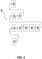
- FIG. 2 a preferred embodiment of a method according to the invention will be described with reference to a flow chart, which is generally designated 200.
- the method begins based on a corresponding start signal or at a particular time.
- step 201 a pressing roller of at least one printing unit is turned on and at least one web tension section is formed.
- all impression rollers are usually hired to the respective pressure rollers and in addition other terminal points such as insertion and / or pull-out closed.
- step 202 a stationary web tension or a stationary register deviation is now effected as quickly as possible.
- the system may pre-register in set-up mode.
- a normal operation can be present in which, for example, a large register deviation can be corrected by means of the method according to the invention.
- a determination of the respective register deviation for at least one printing unit by sensors or by a camera is performed in step 203.
- the determined values are kept available in the system and, if necessary, communicated to a control or a central unit.
- At least one, but generally all downstream impression rollers are shut off at step 204, wherein a selected - suitably the first - printing unit remains closed and serves as a reference against which the axis correction takes place.
- a fast, automatic setting of the register for the individual printing units can now advantageously be effected in step 205
- Basis of the previously determined deviation values are made, not by the very long balancing operations by closed terminal points is delayed.
- the setting takes place on the basis of the deviation of the printing unit itself determined in step 203 and, furthermore, preferably on the basis of a notified register deviation or a communicated control value of one or more further printing units. These cascaded control values can be acted upon by suitable parameters and timers.
- the manipulated variables for the setting are automatically determined preferably in a control unit.
- step 201 ' After carrying out the axis correction takes place at step 201 ', the result substantially corresponds to step 201, a new employment of the impression / impression rollers. This hiring can also be done simultaneously or successively.
- step 202 ' which substantially corresponds to step 202, a stationary web tension or a stationary register deviation, as shown above, is effected again as quickly as possible. As soon as the web tension is constant and the stationary state has been reached, a corresponding pre- or post-registration has been completed.
Description
Die vorliegende Erfindung betrifft ein Verfahren zur automatischen Achskorrektur bei einer Bearbeitungsmaschine zur Bearbeitung einer Warenbahn, ein entsprechendes Computerprogramm sowie ein entsprechendes Computerprogrammprodukt.The present invention relates to a method for automatic axis correction in a processing machine for processing a web, a corresponding computer program and a corresponding computer program product.
Obwohl nachfolgend hauptsächlich auf Druckmaschinen Bezug genommen wird, ist die Erfindung nicht darauf beschränkt, sondern vielmehr auf alle Arten von Bearbeitungsmaschinen gerichtet, bei denen eine Warenbahn bzw. Materialbahn bearbeitet wird. Die Erfindung ist aber insbesondere bei Druckmaschinen, wie z.B. Zeitungsdruckmaschinen, Akzidenzdruckmaschinen, Tiefdruckmaschinen, Verpackungsdruckmaschinen oder Wertpapierdruckmaschinen, sowie bei Verarbeitungsmaschinen, wie z.B. Beutelmaschinen, Briefumschlagsmaschinen oder Verpackungsmaschinen, einsetzbar. Die Warenbahn kann aus Papier, Stoff, Pappe, Kunststoff, Metall, Gummi, in Folienform usw. ausgebildet sein.Although reference will be made hereafter mainly to printing presses, the invention is not limited thereto, but rather directed to all types of machine tools in which a web is processed. However, the invention is particularly applicable to printing machines, such as newspaper printing machines, commercial printing machines, gravure printing machines, packaging printing machines or securities printing machines, as well as processing machines, such as bag machines, envelope machines or packaging machines, can be used. The web can be made of paper, fabric, cardboard, Plastic, metal, rubber, in sheet form, etc. be formed.
Bei betreffenden Bearbeitungsmaschinen, insbesondere bei Druckmaschinen, wird eine Warenbahn entlang von angetriebenen Achsen (Bahntransportachsen bzw.-einrichtungen), wie z.B. Zugwalzen oder Vorschubwalzen, und nicht angetriebenen Achsen, wie z.B. Umlenk-, Leit-, Trocknungs- oder Kühlwalzen, bewegt. Die Warenbahn wird gleichzeitig mittels meist ebenfalls angetriebener Bearbeitungseinrichtungen bearbeitet, beispielsweise bedruckt, gestanzt, geschnitten, gefalzt usw. Die angetriebenen Achsen beeinflussen sowohl die Bahnspannung als auch die jeweilige Längsabweichüng einzelner Bearbeitungseinrichtungen, beispielsweise ein Farb-oder Längsregister.In related processing machines, particularly printing presses, a web is conveyed along driven axes (web transport axes), such as e.g. Pull rolls or feed rolls, and non-driven axes, such as e.g. Deflection, guide, drying or cooling rollers, moved. The web is simultaneously processed by means of mostly likewise driven processing devices, for example printed, stamped, cut, folded, etc. The driven axes influence both the web tension and the respective longitudinal deviation of individual processing devices, for example a color or longitudinal register.
Beim Mehrfarbendruck in Rotationsdruckmaschinen erfolgt der Auftrag der einzelnen Farbauszüge, insbesondere für Cyan, Magenta, Gelb und Schwarz, in aufeinander folgenden Druckwerken. Der Bedruckstoff wird dabei als Rollenmaterial bereitgestellt und endlos durch die Druckeinheit geführt. Maßgeblich für die erreichte Druckqualität ist, dass die Druckbilder der einzelnen Farben übereinander liegen. Das Übereinanderliegen der Druckbilder wird dabei als Register bezeichnet. Zur gegenseitigen Ausrichtung der einzelnen Druckwerke können zusätzlich zu dem eigentlichen Druckbild von jedem Druckwerk Registermessmarken, zum Beispiel in Form von Passerkreuzen, aufgedruckt werden. Anhand dieser Marken kann ein Versatz zwischen den einzelnen Druckbildern durch ein optisches Messsystem online erfasst werden. Bei Rotationsdrucksystemen ist dieses Messsystem im Allgemeinen Bestandteil eines Regelsystems, des sogenannten Registerreglers. Der Registerregler greift dabei über geeignete Stellglieder in den Druckprozess ein und gleicht erkannte Registerabweichungen aus.In multicolor printing in rotary printing presses, the individual color separations are applied, in particular for cyan, magenta, yellow and black, in successive printing units. The printing material is provided as a roll material and passed endlessly through the printing unit. Decisive for the achieved print quality is that the printed images of the individual colors are superimposed. The superposition of the printed images is referred to as a register. For mutual alignment of the individual printing units, register marks, for example in the form of register marks, can be printed on each printing unit in addition to the actual printed image. Using these marks, an offset between the individual print images can be recorded online by means of an optical measuring system. at Rotary pressure systems, this measuring system is generally part of a control system, the so-called register controller. The register controller intervenes via suitable actuators in the printing process and compensates detected register deviations.
Die Ursache für Abweichungen zwischen den einzelnen Drucken sind neben der relativen Position der Druckwerke zueinander Änderungen in der Geometrie des Bedruckstoffes. Diese Geometrieänderungen werden zum Beispiel durch den Einfluss von Feuchtigkeit oder durch zwischen den Druckwerken angeordnete Trocknungseinrichtungen hervorgerufen.The cause of deviations between the individual prints are, in addition to the relative position of the printing units, changes in the geometry of the printing material. These geometry changes are caused for example by the influence of moisture or by arranged between the printing units drying devices.
In der
In der
Die
Es ist erwünscht, die Bahnspannung während des Druckprozesses weitestgehend konstant zu halten, was eine gute Druckqualität ohne wesentliche Korrekturen ermöglicht. Die Reglerparameter des Registerreglers sind auf diesen Betriebszustand angepasst, wodurch der Regler auftretende Registerfehler automatisch ausregeln kann.It is desirable to keep the web tension as constant as possible during the printing process, which allows good print quality without significant corrections. The controller parameters of the register controller are adapted to this operating state, whereby the controller can automatically compensate occurring register errors.
Im Gegensatz dazu existiert eine Regelung zur Voreinstellung eines Registers am Beginn des Druckprozesses (Vorregisterung) bisher nicht. Gemäß dem Stand der Technik wird eine Vorregisterung manuell durch den Drucker durchgeführt.In contrast, a regulation for presetting a register at the beginning of the printing process (Vorregisterung) does not yet exist. According to the prior art, a pre-registration is performed manually by the printer.
Bei einer Tiefdruckmaschine wird eine Klemmstelle üblicherweise durch ein Druckwerk, bei dem eine reibschlüssige Einheit zwischen dem angetriebenen Druckzylinder, einer Gegendruckwalze, dem Presseur und der Materialbahn besteht, definiert. Weitere Klemmstellen werden durch die Ein- und Auszugswerke der Druckmaschine gebildet. Die Warenbahn ist hierdurch in Bahnspannungsabschnitte unterteilbar, wobei ein Bahnspannungsabschnitt von zwei Klemmstellen begrenzt wird. Nach Maschinenstart wird entsprechend dem Stand der Technik durch den Drucker bzw-Drucker zunächst der Presseur des ersten Druckwerks und des zweiten Druckwerks angestellt und hierdurch ein Bahnspannungsabschnitt zwischen den zwei Druckwerke gebildet. Der Drucker wartet ab, bis ein stationärer Zustand erreicht ist, d.h. bis die Bahnspannung oder das Register nur noch durch externe Einflüsse aber nicht mehr aufgrund eines dynamischen Einschwingvorgangs verändert werden. Anschließend liest er die aktuelle Registerabweichung bzw. Achsabweichung, die mittels Sensoren oder mittels eines Kamerasystems gemessen wird, ab. Diese Achsabweichung ist in der Regel relativ groß, so dass der Drucker den Presseur des zweiten Druckwerks abstellt, den zweiten Druckzylinder manuell verstellt und den Presseur danach wieder anstellt. Nachfolgend wird erneut ein stationärer Bahnspannungszustand abgewartet. Nach dieser Ausgleichszeit, die abhängig von der Maschinengeschwindigkeit und der Bahnlänge zwischen den Druckwerken ist, kann nun eine Feinjustierung des Registers der ersten beiden Druckwerke vorgenommen werden. Diesen Vorgang muss der Drucker für alle nachfolgenden Druckwerke wiederholen. Abhängig von der Anzahl der vorhandenen Druckwerke kann dies eine sehr lange Einrichtdauer zur Folge hauben.In a gravure printing press, a nip is usually defined by a printing unit in which there is a frictional engagement between the driven impression cylinder, a platen, the impression roller, and the web. Further clamping points are formed by the insertion and extraction units of the printing press. The web is thereby in Web tension sections divisible, wherein a web tension section is limited by two terminal points. After the machine has been started, according to the prior art, the printer of the first printing unit and of the second printing unit is first set up by the printer or printer and, as a result, a web tension section is formed between the two printing units. The printer waits until a stationary state is reached, ie until the web tension or the register are only changed by external influences but no longer due to a dynamic transient. It then reads the current register deviation or axis deviation, which is measured by means of sensors or by means of a camera system. This axis deviation is usually relatively large, so that the printer off the impression roller of the second printing unit, manually adjusted the second impression cylinder and then hires the impression roller again. Subsequently, a stationary web tension condition is again awaited. After this compensation time, which is dependent on the machine speed and the web length between the printing units, a fine adjustment of the register of the first two printing units can now be made. This process must be repeated by the printer for all subsequent printing units. Depending on the number of existing printing units, this can result in a very long setup time.
Nachteilig an diesem Verfahren gemäß dem Stand der Technik ist, dass die Vorrichtung manuell durch den Drucker erfolgt, der den Wert für die Grobregisterung zudem ungenau von einer Visualisierungsvorrichtung ablesen muss. Ferner muss der Drucker warten, bis der stationäre Maschinenzustand jeweils wieder erreicht wird. Dies kann dazu führen, dass beispielsweise aufgrund fehlerhafter Ablesung oder Eile mit der Vorregisterung stromabwärtiger Druckwerke schon begonnen wird, bevor der stationäre Zustand eines stromaufwärtigen Druckwerks erreicht ist, und daher die Vorregisterung erneut begonnen werden muss. Während der gesamten Einrichtdauer wird Ausschuss (Makulatur) produziert.A disadvantage of this method according to the prior art is that the device is done manually by the printer, which must also read the value for the rough registration inaccurate from a visualization device. Furthermore, the printer must wait until the stationary machine state is reached again. This can lead to the fact that, for example due to erroneous reading or hurry with the Vorregisterung downstream printing units already started before the steady state of an upstream printing unit is reached, and therefore the Vorregisterung must be started again. During the entire set-up period rejects (waste) are produced.
Eine ähnliche Situation besteht, wenn während eines normalen Bearbeitungsvorganges erhebliche Registerabweichungen auftreten (z.B. durch Geschwindigkeitsänderungen). Durch die dynamischen Ausgleichsvorgänge pflanzt sich ein solcher Fehler stromabwärts fort und es kann sehr lange dauern, bis der Fehler ausgeregelt ist.A similar situation exists when significant register deviations occur during a normal machining operation (e.g., due to speed changes). Due to the dynamic compensation processes, such an error propagates downstream and it can take a long time until the error is corrected.
Der Erfindung liegt daher die Aufgabe zugrunde, die Achskorrektur von Bearbeitungseinrichtungen einer bahnverarbeitenden Bearbeitungsmaschine, insbesondere einer bahnverarbeitenden Druckmaschine, zu verbessern bzw. zu beschleunigen.The invention is therefore based on the object, the axis correction of processing facilities of a web-processing machine, in particular a web-processing printing press to improve or accelerate.
Diese Aufgabe wird gelöst durch ein Verfahren zur automatischen Achskorrektur bei einer Bearbeitungsmaschine zur Bearbeitung einer Warenbahn, insbesondere bei einer wellenlosen Druckmaschine, ein Computerprogramm sowie ein Computerprogrammprodukt mit den Merkmalen der unabhängigen Patentansprüche. Vorteilhafte Weiterbildungen sind Gegenstand der Unteransprüche sowie der nachfolgenden Beschreibung.This object is achieved by a method for automatic axis correction in a processing machine for processing a material web, in particular in a shaftless printing press, a computer program and a computer program product with the features of the independent claims. Advantageous developments are the subject of the dependent claims and the following description.
Eine automatische Achskorrektur ist bei einer Bearbeitungsmaschine zur Bearbeitung einer Warenbahn, insbesondere bei einer wellenlosen Druckmaschine, durchführbar, wobei die Warenbahn in wenigstens zwei Bahnspannungsabschnitte unterteilbar ist, wobei ein Bahnspannungsabschnitt von zwei als Transport- oder Bearbeitungseinrichtungen ausgebildeten Klemmstellen begrenzt wird. Es wird eine Achsabweichung von wenigstens einer als Bearbeitungseinrichtung ausgebildeten Klemmstelle bestimmt, anschließend die wenigstens eine Klemmstelle geöffnet, basierend auf der bestimmten Achsabweichung automatisch achskorrigiert und nach der Achskorrektur geschlossen.An automatic axis correction is in a processing machine for processing a web, In particular, in a shaftless printing machine, feasible, wherein the web is subdivided into at least two web tension sections, wherein a web tension section is bounded by two formed as transport or processing means clamping points. An axis deviation of at least one clamping point designed as a processing device is determined, then the at least one clamping point is opened, based on the determined axis deviation automatically corrected by the axis and closed after the axis correction.
Durch die Erfindung wird ein Verfahren zur Achskorrektur bereitgestellt, bei dem Achsen bspw. bei der Vorregisterung automatisch ohne manuelle Verstellung im Wesentlichen parallel korrigiert werden können. Dies führt im Vergleich zu entsprechenden manuellen seriellen Verfahren im Stand der Technik zu einer signifikanten Zeitersparnis und dadurch zu einer deutlichen Verminderung von Ausschuss. Daneben können auch bei einem normalen Produktionsbetrieb insbesondere große Achsabweichungen durch Öffnen der Klemmstelle schnell korrigiert werden, was ebenso zu einer signifikanten Zeitersparnis und dadurch zu einer deutlichen Verminderung von Ausschuss führt.The invention provides a method for axis correction, in which axes can be corrected, for example, in the Vorregister automatically without manual adjustment substantially in parallel. This results in a significant time saving compared to corresponding manual serial methods in the prior art and thereby a significant reduction of rejects. In addition, large axis deviations can be quickly corrected by opening the nip even in a normal production operation, which also leads to a significant time savings and thus to a significant reduction of waste.
Gemäß einer besonders bevorzugten Ausgestaltung wird die wenigstens eine Klemmstelle nach Erreichen eines stationären Zustands bzw. Warenbahntransportzustands geöffnet. Ist ein stationärer Zustand erreicht, werden die Bahnspannung oder das Register nur noch durch externe Einflüsse (Störungen) verändert. Der dynamische Einschwingvorgang ist abgeschlossen. Durch diese Maßnahme kann insbesondere verhindert werden, dass vorläufige Achsabweichungen einer Korrektur zugrunde gelegt werden.According to a particularly preferred embodiment, the at least one nip is opened after reaching a stationary state or web transport state. If a stationary state is reached, the web tension or the register are changed only by external influences (disturbances). The dynamic one Settling process is completed. By means of this measure, it is possible, in particular, to prevent the provisional axis deviations from being based on a correction.
Vorteilhafterweise erfolgt die Bestimmung des stationären Zustands unter Einbeziehung einer Überwachung der Bahnspannung, insbesondere durch Kraftmessung bzw. Bahnspannungsmessung, Bahnspannungsberechnung (bspw. mittels Beobachtung anderer Parameter) und/oder durch eine Überwachung eines Registers. Die Registerüberwachung kann insbesondere optisch erfolgen. Vorteilhafterweise erfolgt die Bestimmung des Erreichens des stationären Zustands durch vorhandene Messtechnik wie Sensoren oder Kameras. Ferner kann eine Überwachung der Bahnspannung mittels Kraftmessdosen oder durch Beobachtung erfolgen. Insbesondere kann vorgesehen sein, in diesem Zusammenhang beispielsweise Passermarken auf der Warenbahn vorzusehen, durch die eine Registerabweichung auf einfache und schnelle Weise erkannt werden kann. Bewegen sich die Bahnspannung und/oder das Register über einen vorgegebenen Zeitraum innerhalb eines vorgegebenen Bereichs, d.h. treten nur geringe Schwankungen auf, kann ein stationärer Zustand angenommen werden.Advantageously, the stationary state is determined by monitoring the web tension, in particular by force measurement or web tension measurement, web tension calculation (for example by monitoring other parameters) and / or by monitoring a register. The register monitoring can be done optically in particular. Advantageously, the determination of the achievement of the stationary state by existing measurement technology such as sensors or cameras. Furthermore, a monitoring of the web tension can be done by means of load cells or by observation. In particular, it may be provided to provide, for example, registration marks on the web in this context, by means of which register deviation can be detected in a simple and rapid manner. The web tension and / or the register move over a predetermined time within a predetermined range, i. If only small fluctuations occur, a steady state can be assumed.
Zweckmäßigerweise wird zusätzlich - zweckmäßigerweise nach dem Erreichen des stationären Zustands -jeweils eine Achsabweichung aller als Bearbeitungseinrichtung ausgebildeten Klemmstellen stromabwärts der wenigstens einen Klemmstelle bestimmt. Die stromabwärtigen Klemmstellen werden geöffnet, basierend jeweils auf der bestimmten Achsabweichung automatisch achskorrigiert und nach der Achskorrektur geschlossen.Expediently, an axis deviation of all clamping points designed as a processing device is additionally determined downstream of the at least one clamping point-suitably after reaching the stationary state. The downstream clamping points are opened, based on the specific axis deviation automatically corrected by the axis and closed after the axis correction.
Das Verfahren kann, insbesondere in der soeben erläuterten Ausgestaltung, vorteilhaft zur automatischen Vorregisterung einer Bearbeitungsmaschine durchgeführt werden, jedoch kann auch vorgesehen sein, das Verfahrenwährend des laufenden Betriebs durchzuführen, beispielsweise, wenn eine Achsabweichung bzw. ein Registerfehler einen vorbestimmten Wert überschreitet und durch eine normale Regelung nicht mehr zeitnah ausgeglichen werden kann, bzw. dies unvorteilhaft erscheint. Hierzu können entsprechende Beurteilungskriterien verwendet werden.The method can be advantageously carried out for the automatic pre-registration of a processing machine, in particular in the embodiment just described, but can also be provided to perform the method during ongoing operation, for example, when an axis deviation or a register error exceeds a predetermined value and by a normal Regulation can no longer be compensated promptly, or this appears unfavorable. For this purpose, appropriate assessment criteria can be used.
In einem ersten Schritt wird die Warenbahn mit einer ersten und wenigstens einer zweiten jeweils als Bearbeitungseinrichtung ausgebildeten Klemmstelle eingeklemmt. Hiermit wird wenigstens ein Bahnspannungsabschnitt ausgebildet. In der Regel werden in diesem Schritt jedoch alle Klemmstellen, d.h. Bearbeitungseinrichtungen und zusätzliche Ein- und/oder Auszugswerke einer entsprechenden Bearbeitungsmaschine, geschlossen. Das Schließen der Klemmstellen kann bei Stillstand der Maschine oder bei niedriger Geschwindigkeit gleichzeitig oder sukzessive erfolgen. Anschließend wird vorzugsweise abgewartet, bis ein stationärer Zustand erreicht ist. Wie bereits oben dargestellt, ist ein stationärer Zustand erreicht, wenn die Bahnspannung und das Register nur noch aufgrund externer Einflüsse bzw. Störungen schwanken, aber sich nicht mehr aufgrund eines dynamischen Einschwingvorgangs verändern. Anschließend wird eine Achsabweichung der wenigstens einen zweiten Klemmstelle bestimmt. Vorzugsweise handelt es sich bei der wenigstens einen zweiten Klemmstelle um alle als Bearbeitungseinrichtung ausgebildeten stromabwärtigen Klemmstellen. Die ermittelten Werte können zunächst im System bzw. innerhalb eines Reglers bereitgehalten werden, wobei innerhalb des Reglers üblicherweise auch Stellwerte für die Achskorrektur bestimmt werden. Nach diesem Schritt wird die wenigstens eine zweite Klemmstelle geöffnet und korrigiert. Hierdurch kann vorteilhafterweise eine schnelle Korrektur auf Basis der zuvor ermittelten Abweichungswerte vorgenommen werden, die nicht durch die sehr langen Ausgleichsvorgänge, die durch geschlossene Klemmstellen hervorgerufen werden, verzögert wird. Die Einstellung erfolgt insbesondere unter Verwendung eines zuvor in einem Regler für die entsprechende Bearbeitungseinrichtung bestimmten Einstellwertes. Nach der Einstellung erfolgt ein Einklemmen der Warenbahn mit der wenigstens einen zweiten Klemmstelle. Wurden gemäß der oben beschriebenen bevorzugten Ausgestaltung Achsabweichungen für alle stromabwärtigen Klemmstellen bestimmt, werden dementsprechend auch alle stromabwärtigen Klemmstellen geöffnet, korrigiert und geschlossen, wobei Öffnen, Korrigieren und Schließen jeweils gleichzeitig oder sukzessive erfolgen können. Damit ist die automatische Vorregisterung abgeschlossen. Es sei an dieser Stelle noch einmal betont, dass zumindest der Schritt des Korrigierens automatisch abläuft, d.h. anhand der maschinell ermittelten Achsabweichungen wird innerhalb einer Recheneinheit, üblicherweise eines Reglers, ein Korrekturstellwert bestimmt, mit dem die geöffnete Klemmstelle beaufschlagt wird. Vorzugsweise läuft jedoch das Verfahren spätestens beginnend mit der Ermittlung der Achsabweichung automatisch ab.In a first step, the material web is clamped with a first and at least one second clamping point designed in each case as a processing device. Hereby, at least one web tension section is formed. In general, however, all clamping points, ie processing facilities and additional input and / or extraction units of a corresponding processing machine are closed in this step. The clamping points can be closed simultaneously or successively when the machine is at a standstill or at low speed. Subsequently, it is preferably waited until a stationary state is reached. As already stated above, a stationary state is achieved when the web tension and the register only fluctuate due to external influences or disturbances, but no longer change due to a dynamic transient process. Subsequently, an axis deviation of the at least one second Terminal point determined. The at least one second clamping point is preferably all downstream clamping points designed as a machining device. The determined values can initially be kept available in the system or within a controller, wherein control values for the axis correction are usually also determined within the controller. After this step, the at least one second nip is opened and corrected. As a result, a rapid correction based on the previously determined deviation values can advantageously be carried out, which is not delayed by the very long compensation processes, which are caused by closed clamping points. The setting takes place, in particular, by using a setting value previously determined in a controller for the corresponding processing device. After adjustment, a trapping of the web takes place with the at least one second nip. If, in accordance with the preferred embodiment described above, axial deviations have been determined for all downstream clamping points, accordingly all downstream clamping points are also opened, corrected and closed, wherein opening, correction and closing can each take place simultaneously or successively. This completes the automatic pre-registration. It should again be emphasized at this point that at least the step of correction takes place automatically, ie, based on the machine-determined axis deviations, a correction control value is determined within a computing unit, usually a controller, with which the opened nip is acted upon. Preferably, however, the method runs automatically at the latest beginning with the determination of the axis deviation.
Es bietet sich an, eine Klemmstelle zur Achskorrektur mit einem Stellbefehl zu beaufschlagen, der basierend auf der bestimmten Achsabweichung, insbesondere von einer Reglereinrichtung, bestimmt wird. Auf diese Weise kann bspw. eine Winkelverstellung, Geschwindigkeitsverstellung oder Lageverstellung der Achse besonders einfach unter Berücksichtigung der Achsabweichung erfolgen.It is advisable to act on a clamping point for axis correction with a control command, which is determined based on the specific axis deviation, in particular by a regulator device. In this way, for example, an angle adjustment, speed adjustment or position adjustment of the axis can be done very easily taking into account the axis deviation.
Zweckmäßigerweise wird der Stellbefehl zusätzlich basierend auf der bestimmten Achsabweichung wenigstens einer weiteren Klemmstelle bestimmt. Es bietet sich an, wenn die weitere Klemmstelle eine stromaufwärtige ist. Weiterhin bietet es sich an, alle stromaufwärtigen Klemmstellen zu berücksichtigen. Insbesondere bei bahnverarbeitenden Maschinen wirkt sich die Verstellung einer Klemmstelle üblicherweise auf den nachfolgenden Warenbahnbereich aus, so dass die Korrektur der stromabwärtigen Achse vorteilhafterweise nicht nur anhand der Achsabweichung dieser Achse, sondern auch anhand der Achsabweichung stromaufwärtiger Achsen durchgeführt wird. Bspw. können die stromaufwärtigen Achsabweichungen dem Regler für die betreffende Klemmstelle zugeführt werden.Expediently, the positioning command is additionally determined based on the specific axle deviation of at least one further clamping point. It makes sense if the other terminal point is an upstream one. Furthermore, it makes sense to consider all upstream clamping points. In particular, in web-processing machines, the adjustment of a nip usually affects the subsequent web area, so that the correction of the downstream axis is advantageously carried out not only on the basis of the axis deviation of this axis, but also on the basis of the axis deviation upstream axes. For example. the upstream axle deviations can be supplied to the controller for the relevant nip.
Vorteilhafterweise wird der Stellbefehl an wenigstens eine weitere Klemmstelle kaskadiert. Es ist insbesondere zweckmäßig, den Stellbefehl an stromabwärtige Achsen zu kaskadieren. Die Kaskadierung kann beispielsweise als Vorsteuerung erfolgen, wobei der kaskadierte Stellbefehl statisch mit zeitunabhängigen Faktoren und/oder mit dynamischen Zeitgliedern beaufschlagt wird. Als Zeitglieder können hierbei beispielsweise PT1-, PT2-, DT1-, DT2- oder Totzeit-Glieder verwendet werden. Auf diese Weise kann eine parallele Achskorrektur insbesondere im Rahmen einer Vorregisterung auf besonders vorteilhafte Weise durchgeführt werden. Die Kaskadierung erfolgt vorteilhafterweise in Abhängigkeit von der gewählte Regelstrategie (z.B. Referenzfarbe, Vorgängerfarbe). Vorgängerfarbe bedeutet, dass die gedruckte Marke des eigenen,Druckwerks mit der Marke des davorliegenden Druckwerks verglichen wird. Daher ist für eine statischen Entkopplung eine Verstellung eines Druckwerks an alle nachfolgenden Druckwerke zu kaskadieren. Referenzfarbe bedeutet, dass alle Druckwerke mit einer festen (in der Regel einer ersten Marke) verglichen und zu dieser geregelt werden. Dies bedingt andere dynamische und statische Kaskadierungsstrategien. Ferner kann bei der Einbeziehung von dynamischen Zeitgliedern insbesondere auch eine Voreinstellung im nichtstatischen Zustand vorgenommen werden. Eine Einstellung einer stromabwärtigen Bearbeitungseinheit ist hierbei möglich, indem der Effekt einer Verstellung einer stromaufwärtigen Einheit als Konstante in Verbindung mit den genannten weitergegebenen Einstellwerten verwendet wird.Advantageously, the control command is cascaded to at least one further nip. It is particularly convenient to cascade the control command to downstream axes. The cascading can be done, for example, as precontrol, wherein the cascaded control command is statically loaded with time-independent factors and / or with dynamic timers. For example, PT1, PT2, DT1, DT2 or dead-time elements can be used as timers. This way a can parallel axis correction can be carried out in a particularly advantageous manner, in particular in the context of a Vorregister. The cascading advantageously takes place as a function of the selected control strategy (eg reference color, predecessor color). Predecessor color means that the printed mark of the own, printing unit is compared with the mark of the preceding printing unit. Therefore, for a static decoupling an adjustment of a printing unit to all subsequent printing units to cascade. Reference color means that all printing works are compared with and fixed to a fixed (usually a first mark). This requires other dynamic and static cascading strategies. Furthermore, with the inclusion of dynamic timers, in particular, a presetting in the non-static state can be made. Adjustment of a downstream processing unit is possible in this case by using the effect of an adjustment of an upstream unit as a constant in conjunction with said passed setting values.
Das erfindungsgemäße Verfahren ist besonders vorteilhaft bei einer als Druckmaschine ausgebildeten Bearbeitungsmaschine einzusetzen, wobei die Klemmstellen aus Einzugs-, Auszugs- und/oder Druckwerke ausgebildet sind. Das Verfahren kann hierbei in besonders günstiger Weise dazu beitragen, die Einrichtdauer bzw. die Vorregisterung einer entsprechenden Druckmaschine zu automatisieren, zeitlich zu verkürzen, und die Produktion von Makulatur zu verringern. Ändert sich im laufenden Betrieb der Druckmaschine die Registereinstellung in einem Ausmaß, das durch normale Regelungssysteme nicht oder zu langsam ausgeglichen werden kann, kann das erfindungsgemäße Verfahren hier zu einer Nachregisterung verwendet werden.The method according to the invention is particularly advantageous for use in a processing machine designed as a printing press, wherein the clamping points are formed from feeder, pull-out and / or printing units. In this case, the method can in a particularly favorable manner contribute to automating, shortening the time required for setting up or pre-registering a corresponding printing press, and to reduce the production of waste paper. As the press progresses, the register setting changes to an extent that normal control systems can not or will not change can be compensated slowly, the process of the invention can be used here for a Nachregisterung.
Bei einer bevorzugten Druckmaschine weist wenigstens ein Druckwerk einen Druckzylinder sowie einen Presseur auf, wobei der Presseur zum Öffnen des Druckwerks in einem variablen von dem Druckzylinder angeordnet werden kann. Es sei beton, dass in keinem der variablen Abstände eine geschlossene Klemmstelle vorliegt. Somit kann vorgesehen sein, den Stellweg wenigstens eines Presseurs verstellbar vorzusehen und vorzugsweise an die Druckwalze anzupassen. Im Stand der Technik werden die Presseure zumeist pneumatisch angestellt, wobei nur ein Standardstellweg vorgesehen ist, entlang dessen der Presseur an- oder abgestellt werden kann. Herkömmliche Presseure können nur in einem festen und üblicherweise sehr großen Abstand von dem Druckzylinder angeordnet werden.In a preferred printing press, at least one printing unit has a printing cylinder and a impression roller, wherein the impression roller can be arranged to open the printing unit in a variable of the printing cylinder. It should be emphasized that in none of the variable distances is there a closed nip. Thus, it can be provided to adjustably provide the travel of at least one impression roller and preferably to adapt to the pressure roller. In the prior art, the impression rollers are usually pneumatically employed, with only a standard travel is provided, along which the impression roller can be switched on or off. Conventional impression rollers can only be arranged at a fixed and usually very large distance from the printing cylinder.
Zweckmäßigerweise wird der Presseur beim Öffnen des Druckwerks zur Achskorrektur in einem ersten Abstand angeordnet. Da in Druckmaschinen unterschiedliche Druckzylindergrößen für die jeweiligen Formate einsetzbar sind, ist der Stellweg im Stand der Technik am größten Durchmesser orientiert und daher der Abstand zwischen dem Druckzylinder und einem abgestellten Presseur bei kleineren Druckzylindern erheblich. Dies führt zu einem Einbruch der Bahnspannung in der Maschine, sobald der Presseur abgestellt wird, weil durch das Abstellen des Presseurs der Bahnweg erheblich verkürzt wird. Gemäß dieser bevorzugten Ausgestaltung der Erfindung können unterschiedliche Verfahrbereiche bzw. Abstände der Presseure abhängig vom Umfang der Druckwalze dazu dienen, dass der Presseur nur minimal vom Druckzylinder abgehoben wird und sich somit der Bahnweg nur in geringem Maße ändert. Wird eine Druckzylinderkorrektur in diesem Maschinenzustand durchgeführt, kann der Presseur wieder angestellt werden, ohne dass dies nennenswerte Änderungen auf das zu bedruckende Material zur Folge hat. Dies führt zu einem erheblich verkürzten Einschwingvorgang. Beim Öffnen des Druckwerks zu einem anderen Zweck als zur Achskorrektur kann der Presseur dann in einem zweiten (großen) Abstand angeordnet werden.Conveniently, the impression roller is arranged at opening the printing unit for axis correction at a first distance. Since in printing presses different printing cylinder sizes can be used for the respective formats, the travel in the prior art is oriented at the largest diameter and therefore the distance between the printing cylinder and a parked impression roller for smaller printing cylinders considerably. This leads to a collapse of the web tension in the machine, as soon as the impression roller is turned off, because the stopping of the impression roller significantly shortens the path. According to this preferred embodiment of the invention, different traversing ranges or distances of the impression rollers can serve depending on the circumference of the pressure roller that the impression roller is lifted only minimally from the printing cylinder and thus the Bahnweg changes only to a small extent. If a print cylinder correction is performed in this machine state, the impression roller can be restarted without significant changes being made to the material to be printed. This leads to a considerably shortened transient process. When opening the printing unit for a purpose other than the axis correction, the impression roller can then be arranged at a second (large) distance.
Die Erfindung betrifft zudem ein Computerprogramm mit Programmcodemitteln, um alle Schritte des erfindungsgemäßen Verfahrens durchzuführen, wenn das Computerprogramm auf einem Computer oder einer entsprechenden Recheneinheit, insbesondere in einer Bearbeitungsmaschine, ausgeführt wird.The invention additionally relates to a computer program with program code means in order to carry out all the steps of the method according to the invention when the computer program is executed on a computer or a corresponding arithmetic unit, in particular in a processing machine.
Das erfindungsgemäß vorgesehene Computerprogrammprodukt mit Programmcodemitteln, die auf einem computerlesbaren Datenträger gespeichert sind, ist zum Durchführen aller Schritte des erfindungsgemäßen Verfahrens ausgebildet, wenn das Computerprogramm auf einem Computer oder einer entsprechenden Recheneinheit, insbesondere in einer Bearbeitungsmaschine ausgeführt wird. Geeignete Datenträger sind insbesondere Disketten, Festplatten, Flashspeicher, EEPROMs, CD-ROMs, DVDs und dergleichen. Auch ein Download eines Programms über Computernetze (Internet, Intranet usw.) ist möglich.The inventively provided computer program product with program code means which are stored on a computer-readable data carrier is designed to perform all the steps of the method according to the invention when the computer program is executed on a computer or a corresponding computing unit, in particular in a processing machine. Suitable data carriers are, in particular, floppy disks, hard disks, flash memories, EEPROMs, CD-ROMs, DVDs and the like. It is also possible to download a program via computer networks (Internet, intranet, etc.).
Weitere Vorteile und Ausgestaltungen der Erfindung ergeben sich aus der Beschreibung und der beiliegenden Zeichnung.Further advantages and embodiments of the invention will become apparent from the description and the accompanying drawings.
Es versteht sich, dass die vorstehend genannten und die nachfolgenden noch zu erläuternden Merkmale nicht nur in der jeweils angegebenen Kombination, sondern auch in anderen Kombinationen oder in Alleinstellung verwendbar sind, ohne den Rahmen der vorliegenden Erfindung zu verlassen.It is understood that the features mentioned above and those yet to be explained can be used not only in the particular combination given, but also in other combinations or in isolation, without departing from the scope of the present invention.
Die Erfindung ist anhand eines Ausführungsbeispiels in der Zeichnung schematisch dargestellt und wird im Folgenden unter Bezugnahme auf die Zeichnung ausführlich beschrieben.The invention is illustrated schematically with reference to an embodiment in the drawing and will be described in detail below with reference to the drawing.
In den Figuren zeigen
- Figur 1
- eine schematische Darstellung einer als Druckmaschine ausgebildeten Bearbeitungsmaschine, die für das erfindungsgemäße Verfahren entsprechend einer besonders bevorzugten Ausführungsform geeignet ist, und
Figur 2- eine schematische Darstellung eines entsprechend einer besonders bevorzugten Ausführungsform der Erfindung ablaufenden Verfahrens.
- FIG. 1
- a schematic representation of a machine designed as a printing machine, which is suitable for the inventive method according to a particularly preferred embodiment, and
- FIG. 2
- a schematic representation of a running according to a particularly preferred embodiment of the invention method.
In
Die Druckmaschine 100 verfügt in der Darstellung über vier hier als Druckwerke 10 ausgebildete Klemmstellen. Es versteht sich jedoch, dass auch eine größere oder kleinere Anzahl an Druckwerken vorgesehen sein kann, ohne von der Erfindung abzuweichen. Die Druckwerke 10 weisen jeweils Druckwalzen 11 auf. Die Druckwalzen 11 sind jeweils mit einem Antrieb, vorzugsweise einem Einzelantrieb (sog. "wellenlose Antriebstechnik"), versehen, der in der Zeichnung jedoch nicht dargestellt ist. Die Druckmaschine 100 ist zur Bearbeitung einer Warenbahn 1, vorliegend einer Papierbahn, ausgebildet.The
Jedes Druckwerk 10 weist ferner einen Presseur 12 auf, mit dem die Papierbahn 1 mit hohem Druck an die Druckwalzen 11 angepresst werden kann. Vorliegend, und durch Auf-/Ab-Pfeile veranschaulicht, sind die Presseure 12 an die Druckwalzen 11, insbesondere über variable, den Druckwalzen 11 anpassbare Stellwege an die Druckwalzen 11 an- bzw. abstellbar.Each
Die Druckmaschine weist weiter hier als ein Einzugswerk 50 und ein Auszugswerk 60 ausgebildete Klemmstellen auf, die jeweils mit Einzugswerksrollen 51 bzw. Auszugswerksrollen 61 versehen sind. Durch die Ein- bzw. Auszugswerkrollen 51, 61 kann eine Klemmverbindung hergestellt werden. Zwischen jeweils zwei Klemmstellen, die durch das Einzugswerk 50, das Auszugswerk 60 und/oder ein Druckwerk 10 definiert werden, sind Bahnspannungsabschnitte ausbildbar.The printing machine further has here as a
In der Druckmaschine sind ferner weitere angetriebene oder nicht angetriebene Rollen vorgesehen, die in der Zeichnung teilweise mit 2 bezeichnet sind. Insbesondere kann es sich hier um Trocknungs-oder Umlenkrollen handeln. Beispielhaft ist in der Zeichnung eine Trocknungseinheit 7 dargestellt, die jedoch aus Gründen der Anschaulichkeit nicht weiter ausgeführt ist.In the printing machine further driven or non-driven rollers are also provided, which are partially designated in the drawing with 2. In particular, these may be drying or deflection rollers. By way of example, a
Die dargestellte Druckmaschine weist ferner Sensoren 15 auf, die insbesondere als optische Bestimmungsmittel und/oder Bahnspannungssenscren bzw. Kraftmessdosen ausgeführt sein können. Über die Sensoren 15 kann insbesondere ein stationärer Registerzustand und/oder Bahnspannungszustand, der vorzugsweise nach dem Schließen der Klemmstellen erreicht werden soll, überwacht werden. Die Sensoren 15 sind über eine Datenleitung 35 mit einer Auswerte-und Regeleinheit 30 verbunden.The illustrated printing machine further has
Die Einheit 30 beinhaltet vorzugsweise eine Recheneinheit zur Durchführung des erfindungsgemäßen Verfahrens. Nicht dargestellt sind weitere Kanäle, über die die Auswerteeinheit 30 eine Registerkorrektur, insbesondere entsprechend einer vorteilhaften Ausgestaltung in kaskadierender Weise, vornimmt.The
In
Bei Schritt 210 beginnt das Verfahren aufgrund eines entsprechenden Startsignals oder zu einem bestimmten Zeitpunkt.At
Bei Schritt 201 wird ein Presseur wenigstens eines Druckwerks angestellt und wenigstens ein Bahnspannungsabschnitt ausgebildet. Wie oben dargestellt, werden jedoch in der Regel in diesem Schritt alle Presseure an die jeweiligen Druckwalzen angestellt und zusätzlich andere Klemmstellen wie z.B. Ein- und/oder Auszugswerk geschlossen. Bei Schritt 202 wird nun möglichst schnell eine stationäre Bahnspannung bzw. eine stationäre Registerabweichung bewirkt. Nach Durchführung des Schritts 202 kann das System beispielsweise im Einrichtmodus zur Vorregisterung laufen. Ebenso kann ein Normalbetrieb vorliegen, bei dem beispielsweise eine große Registerabweichung mittels des erfindungsgemäßen Verfahrens korrigiert werden kann.In
Nach dem Erreichen des stationären Zustands wird in Schritt 203 eine Bestimmung der jeweiligen Registerabweichung für wenigstens ein Druckwerk durch Sensoren oder durch eine Kamera durchgeführt. Die ermittelten Werte werden im System bereitgehalten und gegebenenfalls einer Steuerung bzw. einer Zentraleinheit mitgeteilt.After reaching the stationary state, a determination of the respective register deviation for at least one printing unit by sensors or by a camera is performed in
Nach dieser Messung erfolgt ein Abstellen wenigstens eines, in der Regel aber aller stromabwärtigen Presseure bei Schritt 204, wobei ein ausgewähltes - zweckmäßigerweise das erste - Druckwerk geschlossen bleibt und als Referenz dient, gegenüber der die Achskorrektur erfolgt.After this measurement, at least one, but generally all downstream impression rollers are shut off at
Durch das Öffnen der Presseure (idealerweise ein möglichst geringes Abheben der Presseure, um durch die hierdurch hervorgerufene Längenänderung zwischen den Druckwerken keine großen Bahnspannungsänderungen zu erzeugen) der einzelnen Druckwerke kann in Schritt 205 nun vorteilhafterweise eine schnelle, automatische Einstellung des Registers für die einzelnen Druckwerke auf Basis der zuvor ermittelten Abweichungswerte vorgenommen werden, die nicht durch die sehr langen Ausgleichsvorgänge, die durch geschlossenen Klemmstellen hervorgerufen werden, verzögert wird. Die Einstellung erfolgt hierbei einerseits der auf Basis der in Schritt 203 bestimmten Abweichung des Druckwerks selbst und ferner zudem vorzugsweise aufgrund einer mitgeteilten Registerabweichung bzw. eines mitgeteilten Stellwerts eines oder mehrerer weiterer Druckwerke. Diese kaskadierten Stellwerte können durch geeignete Parameter und Zeitglieder beaufschlagt sein. Die Stellgrößen für die Einstellung werden automatisch vorzugsweise in einer Regeleinheit bestimmt.By opening the impression rollers (ideally the lowest possible lifting of the impression rollers in order not to produce large changes in web tension due to the change in length between the printing units caused thereby) of the individual printing units, a fast, automatic setting of the register for the individual printing units can now advantageously be effected in
Nach Durchführung der Achskorrektur erfolgt bei Schritt 201', dessen Ergebnis im wesentlichen Schritt 201 entspricht, eine erneute Anstellung des Presseurs/der Presseure. Auch dieses Anstellen kann gleichzeitig oder sukzessive erfolgen.After carrying out the axis correction takes place at step 201 ', the result substantially corresponds to step 201, a new employment of the impression / impression rollers. This hiring can also be done simultaneously or successively.
In Schritt 202', der im wesentlichen Schritt 202 entspricht, wird erneut möglichst schnell eine stationäre Bahnspannung bzw. eine stationäre Registerabweichung, wie oben dargestellt, bewirkt. Sobald die Bahnspannung konstant ist und der stationäre Zustand erreicht wurde, ist eine entsprechende Vor- bzw. Nachregisterung abgeschlossen.In step 202 ', which substantially corresponds to step 202, a stationary web tension or a stationary register deviation, as shown above, is effected again as quickly as possible. As soon as the web tension is constant and the stationary state has been reached, a corresponding pre- or post-registration has been completed.
Dies kann in Schritt 220 dem Benutzer bekanntgegeben werden, bzw. kann hier beispielsweise ein Freigabesignal für weitere Verfahrensschritte bereitgestellt werden.This can be announced to the user in
Es versteht sich, dass in der dargestellten Figur nur eine beispielhafte Ausführungsform der Erfindung dargestellt ist. Daneben ist jede andere Ausführungsform denkbar, ohne den Rahmen dieser Erfindung zu verlassen.It is understood that in the illustrated figure, only an exemplary embodiment of the invention is shown. In addition, any other embodiment is conceivable without departing from the scope of this invention.
- 11
- Warenbahnweb
- 22
- Rollenroll
- 77
- Trocknerdryer
- 88th
- Kompensatorcompensator
- 99
- KompensatorrolleKompensatorrolle
- 1010
- Druckwerkprinting unit
- 1111
- Druckwalzeplaten
- 1212
- Presseurimpression roller
- 1515
- Sensorsensor
- 3030
- Auswerte- und RegelungseinheitEvaluation and control unit
- 3535
- Datenleitungdata line
- 5050
- Einzugswerkinfeed
- 5151
- EinzugswerksrolleInfeed roller
- 6060
- Auszugswerkexcerpt
- 6161
- AuszugswerksrolleOutfeed roller
- 100100
- Bearbeitungsmaschineprocessing machine
- 200200
- Flussdiagrammflow chart
- 201 - 220201 - 220
- Verfahrensschrittesteps
Claims (13)
- Method for automatic axis correction in a processing machine for processing a product web (1),
wherein the product web (1) is subdividable into at least two web tension sections, a web tension section being delimited by two clamping points (10, 50, 60) formed as transport (50, 60) or processing devices (10),
wherein a register deviation of at least one clamping point formed as a processing device (10) is determined,
the at least one clamping point (10) is then opened, the axis thereof is automatically corrected on the basis of the register deviation determined and said clamping point is closed after the axis correction,
wherein the processing machine is constructed as a printing press (100) and the at least one clamping point (10) is formed as printing unit (10), characterized in that the printing unit (10) has a printing cylinder (11) and an impression roll (12), the impression roll (12) being arranged at a variable distance from the printing cylinder (11) to open the printing unit (10). - Method according to Claim 1, wherein the at least one clamping point (10) is opened during a steady product web transport state.
- Method according to Claim 2, wherein the steady product web transport state is determined by means of monitoring the web tension and/or by monitoring the register deviation.
- Method according to one of the preceding claims, wherein in addition in each case a register deviation of all the clamping points formed as a processing device (10) downstream of the at least one clamping point (10) is determined, the downstream clamping points (10) are opened, the axes thereof are corrected automatically, in each case on the basis of the register deviation determined, and said clamping points are closed after the axis correction.
- Method according to one of the preceding claims, which is performed for the pre-registration of the processing machine (100).
- Method according to Claim 5, comprising the following steps:clamping the product web (1) in by using a first clamping point and at least one second clamping point (10), in each case formed as a processing device,determining a register deviation of the at least one second clamping point (10),opening the at least one second clamping point (10),automatically correcting the axis of the at least one second clamping point (10),clamping the product web (1) in by using the at least one second clamping point (10).
- Method according to one of the preceding claims, wherein a clamping point (10, 50, 60) for axis correction has applied to it an actuating command which is determined on the basis of the register deviation determined for this clamping point.
- Method according to Claim 7, wherein the actuating command is additionally determined on the basis of the register deviation determined for at least one further, preferably upstream, clamping point (10, 50, 60).
- Method according to Claim 7 or 8, wherein the actuating command is cascaded to at least one further, preferably downstream, clamping point (10, 50, 60).
- Method according to one of the preceding claims, wherein the impression roll (12) is arranged at a first distance as the printing unit (10) is opened for the purpose of axis correction.
- Computing unit which is set up to carry out a method according to one of the preceding claims.
- Computer program which allows a computer to carry out a method according to one of Claims 1 to 10 when the computer program is executed on the computer.
- Computer-readable data storage medium on which a computer program according to Claim 12 is stored.
Applications Claiming Priority (2)
| Application Number | Priority Date | Filing Date | Title |
|---|---|---|---|
| DE102008053406A DE102008053406A1 (en) | 2008-10-27 | 2008-10-27 | Method for automatic axis correction in a processing machine for processing a material web |
| PCT/EP2009/006313 WO2010049030A2 (en) | 2008-10-27 | 2009-09-01 | Automatic axis correction method for use in a treatment machine for treating a material web |
Publications (2)
| Publication Number | Publication Date |
|---|---|
| EP2349721A2 EP2349721A2 (en) | 2011-08-03 |
| EP2349721B1 true EP2349721B1 (en) | 2016-03-23 |
Family
ID=41821088
Family Applications (1)
| Application Number | Title | Priority Date | Filing Date |
|---|---|---|---|
| EP09778239.5A Active EP2349721B1 (en) | 2008-10-27 | 2009-09-01 | Automatic axis correction method for use in a treatment machine for treating a material web |
Country Status (5)
| Country | Link |
|---|---|
| US (1) | US20110252989A1 (en) |
| EP (1) | EP2349721B1 (en) |
| CN (1) | CN102196914A (en) |
| DE (1) | DE102008053406A1 (en) |
| WO (1) | WO2010049030A2 (en) |
Families Citing this family (9)
| Publication number | Priority date | Publication date | Assignee | Title |
|---|---|---|---|---|
| DE102011121319A1 (en) * | 2011-12-16 | 2013-06-20 | Gallus Stanz- Und Druckmaschinen Gmbh | Gravure printing unit with web tension compensation and method for servicing such a gravure printing unit |
| DE102012002724A1 (en) * | 2012-02-10 | 2013-08-14 | Robert Bosch Gmbh | Method for regulating web tension in processing machine used for processing product web e.g. shaftless printing press, involves delaying effect of regulation output value on actuating command for second actuator by delay time |
| AT512359A3 (en) | 2011-12-29 | 2015-09-15 | Bosch Gmbh Robert | Method for controlling a web tension in a processing machine |
| CN102529314A (en) * | 2012-01-13 | 2012-07-04 | 南通华一高科印刷机械有限公司 | Door type four-roller dual-deviation rectification device of offset printing machine |
| DE102012002675A1 (en) | 2012-02-10 | 2013-08-14 | Robert Bosch Gmbh | Method for register correction in a web-processing machine with a delay section |
| DE102012013435A1 (en) * | 2012-04-04 | 2013-10-10 | Robert Bosch Gmbh | Method for pre-registering a processing station |
| DE102012109949A1 (en) * | 2012-10-18 | 2014-05-22 | Baumer Hhs Gmbh | Method and device for passport measurement and / or register correction |
| DE102017210170A1 (en) | 2017-06-19 | 2018-12-20 | Heidelberger Druckmaschinen Ag | Rotary gravure printing unit with draw roller |
| CN110509680B (en) * | 2019-09-10 | 2020-12-29 | 深圳市冠为科技股份有限公司 | Printing registration method and system |
Citations (1)
| Publication number | Priority date | Publication date | Assignee | Title |
|---|---|---|---|---|
| US20050247229A1 (en) * | 2004-05-04 | 2005-11-10 | Heidelberger Druckmaschinen Ag | Web printing press and method for controlling print-to-cut and/or circumferential register |
Family Cites Families (15)
| Publication number | Priority date | Publication date | Assignee | Title |
|---|---|---|---|---|
| GB2182889A (en) * | 1985-09-28 | 1987-05-28 | George Moulton Successors Limi | Proofing presses |
| DE19527199C2 (en) * | 1995-07-26 | 2002-10-31 | Baumueller Nuernberg Gmbh | Flexographic printing machine and its use |
| DK0950519T3 (en) * | 1998-04-16 | 2001-12-17 | Abb Ind Ag | Method for self-adjusting color and cut registers in multi-lane rotary printing machines |
| DE10035787C2 (en) * | 2000-07-22 | 2002-05-16 | Koenig & Bauer Ag | Process for regulating a web tension |
| DE10135773C5 (en) * | 2001-07-23 | 2009-07-09 | Koenig & Bauer Aktiengesellschaft | Method and device for controlling drives of a printing machine |
| US20030226431A1 (en) * | 2002-06-05 | 2003-12-11 | Marcel Motard | Paper perforation system |
| DE10335885A1 (en) * | 2003-08-06 | 2005-03-17 | Man Roland Druckmaschinen Ag | Method and device for regulating the web tension and the cutting register error of a web-fed rotary printing press |
| DE10345593A1 (en) * | 2003-09-29 | 2005-07-07 | Koenig & Bauer Ag | Method for determining production-relevant material properties of the substrates and / or elevators |
| DE102005045456B4 (en) * | 2005-09-22 | 2008-12-18 | Koenig & Bauer Aktiengesellschaft | Method for starting a printing press |
| DE102006004307B4 (en) * | 2006-01-31 | 2013-08-14 | Windmöller & Hölscher Kg | Method for measuring and adjusting web tension between inking units of a multicolor machine |
| ATE456456T1 (en) * | 2006-05-23 | 2010-02-15 | Koenig & Bauer Ag | ARRANGEMENTS IN A PRINTING UNIT OF A ROTARY PRINTING PRESS |
| JP2008105277A (en) * | 2006-10-25 | 2008-05-08 | Mitsubishi Heavy Ind Ltd | Operating method of printing machine, and printing machine |
| DE102007024323A1 (en) * | 2007-05-24 | 2008-11-27 | Robert Bosch Gmbh | Method for the dynamic adjustment of a printing machine module for correcting a first index comprises changing the first register and decoupling further registers using a first correction value for the module |
| DE102007053527A1 (en) * | 2007-11-09 | 2009-05-14 | Robert Bosch Gmbh | Method for adjusting the web tension in a processing machine |
| DE102007059066A1 (en) * | 2007-12-07 | 2009-06-10 | Robert Bosch Gmbh | Axis correction method for a processing machine and a processing machine |
-
2008
- 2008-10-27 DE DE102008053406A patent/DE102008053406A1/en not_active Withdrawn
-
2009
- 2009-09-01 US US13/126,148 patent/US20110252989A1/en not_active Abandoned
- 2009-09-01 EP EP09778239.5A patent/EP2349721B1/en active Active
- 2009-09-01 WO PCT/EP2009/006313 patent/WO2010049030A2/en active Application Filing
- 2009-09-01 CN CN2009801424766A patent/CN102196914A/en active Pending
Patent Citations (1)
| Publication number | Priority date | Publication date | Assignee | Title |
|---|---|---|---|---|
| US20050247229A1 (en) * | 2004-05-04 | 2005-11-10 | Heidelberger Druckmaschinen Ag | Web printing press and method for controlling print-to-cut and/or circumferential register |
Also Published As
| Publication number | Publication date |
|---|---|
| WO2010049030A2 (en) | 2010-05-06 |
| CN102196914A (en) | 2011-09-21 |
| WO2010049030A3 (en) | 2010-07-22 |
| US20110252989A1 (en) | 2011-10-20 |
| DE102008053406A1 (en) | 2010-04-29 |
| EP2349721A2 (en) | 2011-08-03 |
Similar Documents
| Publication | Publication Date | Title |
|---|---|---|
| EP2349721B1 (en) | Automatic axis correction method for use in a treatment machine for treating a material web | |
| DE102007049670B4 (en) | Method for register correction in a processing machine and processing machine | |
| WO2003016059A1 (en) | Method and device for controlling the drive units in a printing machine | |
| WO2010057636A1 (en) | Method for axis correction in a processing machine and processing machine | |
| EP2072253A2 (en) | Method for controlling the tension of a sheet and/or the register | |
| EP1981791B1 (en) | Device and method for measuring and setting the web tension between inking stations of a multicolor press | |
| EP1759844B1 (en) | Process for printing correcting | |
| DE102007037564B4 (en) | Method for axis correction in a processing machine | |
| DE102011101842A1 (en) | Method of controlling web tension in a web-processing machine | |
| EP2067725A2 (en) | Method of correcting the axis in a processing machine and processing machine | |
| EP2064060B1 (en) | Method for determining a repeat length/web tension function on a printing press, and regulating auxiliary apparatus for carrying it out | |
| DE10058841A1 (en) | Procedure for regulating a size register | |
| DE102012013435A1 (en) | Method for pre-registering a processing station | |
| DE102009052330A1 (en) | Method for controlling a controlled variable in a processing machine | |
| DE102007024323A1 (en) | Method for the dynamic adjustment of a printing machine module for correcting a first index comprises changing the first register and decoupling further registers using a first correction value for the module | |
| DE102008062531A1 (en) | Method for controlling e.g. color register in newspaper printing machine, involves determining web tension in tension sections before correction of register, where correction is implemented dependent upon web tension | |
| EP2189288B1 (en) | Method for regulating a processing machine with at least one regulating device | |
| DE102007034835A1 (en) | Shaftless printing machine e.g. cardboard printing machine, operating method, involves presetting processing length of printed product by speeds of driven processing axle i.e. ink-transferring axle | |
| DE102006023825A1 (en) | Method and system for controlling the drive of a printing and / or processing machine | |
| DE102006060212B4 (en) | Printing machine for printing substrate webs and method for setting and maintaining the register of such a printing press | |
| EP1980396A2 (en) | Method for adjusting printing press modules | |
| DE102012017575A1 (en) | Method for controlling processing register in processing machine for processing web, involves specifying controller parameter as function of variable clamp, when controlled value of controller parameter is controlled by control device | |
| DE102006047846A1 (en) | Processing machine i.e. printing machine, operating method for gravure printing press, involves driving rolls of printing machine for processing of goods path and chill rolls and/or guide rolls, which are driven by themselves |
Legal Events
| Date | Code | Title | Description |
|---|---|---|---|
| PUAI | Public reference made under article 153(3) epc to a published international application that has entered the european phase |
Free format text: ORIGINAL CODE: 0009012 |
|
| 17P | Request for examination filed |
Effective date: 20110527 |
|
| AK | Designated contracting states |
Kind code of ref document: A2 Designated state(s): AT BE BG CH CY CZ DE DK EE ES FI FR GB GR HR HU IE IS IT LI LT LU LV MC MK MT NL NO PL PT RO SE SI SK SM TR |
|
| DAX | Request for extension of the european patent (deleted) | ||
| 17Q | First examination report despatched |
Effective date: 20121120 |
|
| GRAP | Despatch of communication of intention to grant a patent |
Free format text: ORIGINAL CODE: EPIDOSNIGR1 |
|
| INTG | Intention to grant announced |
Effective date: 20151202 |
|
| GRAS | Grant fee paid |
Free format text: ORIGINAL CODE: EPIDOSNIGR3 |
|
| GRAA | (expected) grant |
Free format text: ORIGINAL CODE: 0009210 |
|
| AK | Designated contracting states |
Kind code of ref document: B1 Designated state(s): AT BE BG CH CY CZ DE DK EE ES FI FR GB GR HR HU IE IS IT LI LT LU LV MC MK MT NL NO PL PT RO SE SI SK SM TR |
|
| REG | Reference to a national code |
Ref country code: GB Ref legal event code: FG4D Free format text: NOT ENGLISH |
|
| REG | Reference to a national code |
Ref country code: CH Ref legal event code: EP |
|
| REG | Reference to a national code |
Ref country code: AT Ref legal event code: REF Ref document number: 782733 Country of ref document: AT Kind code of ref document: T Effective date: 20160415 |
|
| REG | Reference to a national code |
Ref country code: IE Ref legal event code: FG4D Free format text: LANGUAGE OF EP DOCUMENT: GERMAN |
|
| REG | Reference to a national code |
Ref country code: DE Ref legal event code: R096 Ref document number: 502009012313 Country of ref document: DE |
|
| REG | Reference to a national code |
Ref country code: LT Ref legal event code: MG4D |
|
| REG | Reference to a national code |
Ref country code: NL Ref legal event code: MP Effective date: 20160323 |
|
| PG25 | Lapsed in a contracting state [announced via postgrant information from national office to epo] |
Ref country code: FI Free format text: LAPSE BECAUSE OF FAILURE TO SUBMIT A TRANSLATION OF THE DESCRIPTION OR TO PAY THE FEE WITHIN THE PRESCRIBED TIME-LIMIT Effective date: 20160323 Ref country code: NO Free format text: LAPSE BECAUSE OF FAILURE TO SUBMIT A TRANSLATION OF THE DESCRIPTION OR TO PAY THE FEE WITHIN THE PRESCRIBED TIME-LIMIT Effective date: 20160623 Ref country code: GR Free format text: LAPSE BECAUSE OF FAILURE TO SUBMIT A TRANSLATION OF THE DESCRIPTION OR TO PAY THE FEE WITHIN THE PRESCRIBED TIME-LIMIT Effective date: 20160624 |
|
| PG25 | Lapsed in a contracting state [announced via postgrant information from national office to epo] |
Ref country code: NL Free format text: LAPSE BECAUSE OF FAILURE TO SUBMIT A TRANSLATION OF THE DESCRIPTION OR TO PAY THE FEE WITHIN THE PRESCRIBED TIME-LIMIT Effective date: 20160323 Ref country code: SE Free format text: LAPSE BECAUSE OF FAILURE TO SUBMIT A TRANSLATION OF THE DESCRIPTION OR TO PAY THE FEE WITHIN THE PRESCRIBED TIME-LIMIT Effective date: 20160323 Ref country code: LT Free format text: LAPSE BECAUSE OF FAILURE TO SUBMIT A TRANSLATION OF THE DESCRIPTION OR TO PAY THE FEE WITHIN THE PRESCRIBED TIME-LIMIT Effective date: 20160323 Ref country code: LV Free format text: LAPSE BECAUSE OF FAILURE TO SUBMIT A TRANSLATION OF THE DESCRIPTION OR TO PAY THE FEE WITHIN THE PRESCRIBED TIME-LIMIT Effective date: 20160323 |
|
| PG25 | Lapsed in a contracting state [announced via postgrant information from national office to epo] |
Ref country code: EE Free format text: LAPSE BECAUSE OF FAILURE TO SUBMIT A TRANSLATION OF THE DESCRIPTION OR TO PAY THE FEE WITHIN THE PRESCRIBED TIME-LIMIT Effective date: 20160323 Ref country code: PL Free format text: LAPSE BECAUSE OF FAILURE TO SUBMIT A TRANSLATION OF THE DESCRIPTION OR TO PAY THE FEE WITHIN THE PRESCRIBED TIME-LIMIT Effective date: 20160323 Ref country code: IS Free format text: LAPSE BECAUSE OF FAILURE TO SUBMIT A TRANSLATION OF THE DESCRIPTION OR TO PAY THE FEE WITHIN THE PRESCRIBED TIME-LIMIT Effective date: 20160723 |
|
| PG25 | Lapsed in a contracting state [announced via postgrant information from national office to epo] |
Ref country code: SK Free format text: LAPSE BECAUSE OF FAILURE TO SUBMIT A TRANSLATION OF THE DESCRIPTION OR TO PAY THE FEE WITHIN THE PRESCRIBED TIME-LIMIT Effective date: 20160323 Ref country code: ES Free format text: LAPSE BECAUSE OF FAILURE TO SUBMIT A TRANSLATION OF THE DESCRIPTION OR TO PAY THE FEE WITHIN THE PRESCRIBED TIME-LIMIT Effective date: 20160323 Ref country code: CZ Free format text: LAPSE BECAUSE OF FAILURE TO SUBMIT A TRANSLATION OF THE DESCRIPTION OR TO PAY THE FEE WITHIN THE PRESCRIBED TIME-LIMIT Effective date: 20160323 Ref country code: PT Free format text: LAPSE BECAUSE OF FAILURE TO SUBMIT A TRANSLATION OF THE DESCRIPTION OR TO PAY THE FEE WITHIN THE PRESCRIBED TIME-LIMIT Effective date: 20160725 Ref country code: SM Free format text: LAPSE BECAUSE OF FAILURE TO SUBMIT A TRANSLATION OF THE DESCRIPTION OR TO PAY THE FEE WITHIN THE PRESCRIBED TIME-LIMIT Effective date: 20160323 Ref country code: RO Free format text: LAPSE BECAUSE OF FAILURE TO SUBMIT A TRANSLATION OF THE DESCRIPTION OR TO PAY THE FEE WITHIN THE PRESCRIBED TIME-LIMIT Effective date: 20160323 |
|
| REG | Reference to a national code |
Ref country code: DE Ref legal event code: R097 Ref document number: 502009012313 Country of ref document: DE |
|
| PLBE | No opposition filed within time limit |
Free format text: ORIGINAL CODE: 0009261 |
|
| STAA | Information on the status of an ep patent application or granted ep patent |
Free format text: STATUS: NO OPPOSITION FILED WITHIN TIME LIMIT |
|
| PG25 | Lapsed in a contracting state [announced via postgrant information from national office to epo] |
Ref country code: DK Free format text: LAPSE BECAUSE OF FAILURE TO SUBMIT A TRANSLATION OF THE DESCRIPTION OR TO PAY THE FEE WITHIN THE PRESCRIBED TIME-LIMIT Effective date: 20160323 |
|
| PG25 | Lapsed in a contracting state [announced via postgrant information from national office to epo] |
Ref country code: BE Free format text: LAPSE BECAUSE OF NON-PAYMENT OF DUE FEES Effective date: 20160930 Ref country code: BG Free format text: LAPSE BECAUSE OF FAILURE TO SUBMIT A TRANSLATION OF THE DESCRIPTION OR TO PAY THE FEE WITHIN THE PRESCRIBED TIME-LIMIT Effective date: 20160623 |
|
| 26N | No opposition filed |
Effective date: 20170102 |
|
| PG25 | Lapsed in a contracting state [announced via postgrant information from national office to epo] |
Ref country code: MC Free format text: LAPSE BECAUSE OF FAILURE TO SUBMIT A TRANSLATION OF THE DESCRIPTION OR TO PAY THE FEE WITHIN THE PRESCRIBED TIME-LIMIT Effective date: 20160323 |
|
| REG | Reference to a national code |
Ref country code: CH Ref legal event code: PL |
|
| GBPC | Gb: european patent ceased through non-payment of renewal fee |
Effective date: 20160901 |
|
| PG25 | Lapsed in a contracting state [announced via postgrant information from national office to epo] |
Ref country code: SI Free format text: LAPSE BECAUSE OF FAILURE TO SUBMIT A TRANSLATION OF THE DESCRIPTION OR TO PAY THE FEE WITHIN THE PRESCRIBED TIME-LIMIT Effective date: 20160323 |
|
| REG | Reference to a national code |
Ref country code: IE Ref legal event code: MM4A |
|
| REG | Reference to a national code |
Ref country code: FR Ref legal event code: ST Effective date: 20170531 |
|
| PG25 | Lapsed in a contracting state [announced via postgrant information from national office to epo] |
Ref country code: GB Free format text: LAPSE BECAUSE OF NON-PAYMENT OF DUE FEES Effective date: 20160901 Ref country code: LI Free format text: LAPSE BECAUSE OF NON-PAYMENT OF DUE FEES Effective date: 20160930 Ref country code: FR Free format text: LAPSE BECAUSE OF NON-PAYMENT OF DUE FEES Effective date: 20160930 Ref country code: CH Free format text: LAPSE BECAUSE OF NON-PAYMENT OF DUE FEES Effective date: 20160930 Ref country code: IE Free format text: LAPSE BECAUSE OF NON-PAYMENT OF DUE FEES Effective date: 20160901 |
|
| PG25 | Lapsed in a contracting state [announced via postgrant information from national office to epo] |
Ref country code: LU Free format text: LAPSE BECAUSE OF NON-PAYMENT OF DUE FEES Effective date: 20160901 |
|
| REG | Reference to a national code |
Ref country code: AT Ref legal event code: MM01 Ref document number: 782733 Country of ref document: AT Kind code of ref document: T Effective date: 20160901 |
|
| REG | Reference to a national code |
Ref country code: BE Ref legal event code: MM Effective date: 20160930 |
|
| PG25 | Lapsed in a contracting state [announced via postgrant information from national office to epo] |
Ref country code: AT Free format text: LAPSE BECAUSE OF NON-PAYMENT OF DUE FEES Effective date: 20160901 |
|
| PG25 | Lapsed in a contracting state [announced via postgrant information from national office to epo] |
Ref country code: HU Free format text: LAPSE BECAUSE OF FAILURE TO SUBMIT A TRANSLATION OF THE DESCRIPTION OR TO PAY THE FEE WITHIN THE PRESCRIBED TIME-LIMIT; INVALID AB INITIO Effective date: 20090901 Ref country code: CY Free format text: LAPSE BECAUSE OF FAILURE TO SUBMIT A TRANSLATION OF THE DESCRIPTION OR TO PAY THE FEE WITHIN THE PRESCRIBED TIME-LIMIT Effective date: 20160323 |
|
| PG25 | Lapsed in a contracting state [announced via postgrant information from national office to epo] |
Ref country code: TR Free format text: LAPSE BECAUSE OF FAILURE TO SUBMIT A TRANSLATION OF THE DESCRIPTION OR TO PAY THE FEE WITHIN THE PRESCRIBED TIME-LIMIT Effective date: 20160323 Ref country code: MT Free format text: LAPSE BECAUSE OF FAILURE TO SUBMIT A TRANSLATION OF THE DESCRIPTION OR TO PAY THE FEE WITHIN THE PRESCRIBED TIME-LIMIT Effective date: 20160323 Ref country code: HR Free format text: LAPSE BECAUSE OF FAILURE TO SUBMIT A TRANSLATION OF THE DESCRIPTION OR TO PAY THE FEE WITHIN THE PRESCRIBED TIME-LIMIT Effective date: 20160323 Ref country code: MK Free format text: LAPSE BECAUSE OF FAILURE TO SUBMIT A TRANSLATION OF THE DESCRIPTION OR TO PAY THE FEE WITHIN THE PRESCRIBED TIME-LIMIT Effective date: 20160323 |
|
| PGFP | Annual fee paid to national office [announced via postgrant information from national office to epo] |
Ref country code: IT Payment date: 20190920 Year of fee payment: 11 |
|
| PG25 | Lapsed in a contracting state [announced via postgrant information from national office to epo] |
Ref country code: IT Free format text: LAPSE BECAUSE OF NON-PAYMENT OF DUE FEES Effective date: 20200901 |
|
| PGFP | Annual fee paid to national office [announced via postgrant information from national office to epo] |
Ref country code: DE Payment date: 20231124 Year of fee payment: 15 |