EP2067725A2 - Method of correcting the axis in a processing machine and processing machine - Google Patents
Method of correcting the axis in a processing machine and processing machine Download PDFInfo
- Publication number
- EP2067725A2 EP2067725A2 EP08018275A EP08018275A EP2067725A2 EP 2067725 A2 EP2067725 A2 EP 2067725A2 EP 08018275 A EP08018275 A EP 08018275A EP 08018275 A EP08018275 A EP 08018275A EP 2067725 A2 EP2067725 A2 EP 2067725A2
- Authority
- EP
- European Patent Office
- Prior art keywords
- web
- web tension
- driven
- processing machine
- inertia
- Prior art date
- Legal status (The legal status is an assumption and is not a legal conclusion. Google has not performed a legal analysis and makes no representation as to the accuracy of the status listed.)
- Granted
Links
Images

Classifications
-
- B—PERFORMING OPERATIONS; TRANSPORTING
- B65—CONVEYING; PACKING; STORING; HANDLING THIN OR FILAMENTARY MATERIAL
- B65H—HANDLING THIN OR FILAMENTARY MATERIAL, e.g. SHEETS, WEBS, CABLES
- B65H23/00—Registering, tensioning, smoothing or guiding webs
- B65H23/04—Registering, tensioning, smoothing or guiding webs longitudinally
- B65H23/18—Registering, tensioning, smoothing or guiding webs longitudinally by controlling or regulating the web-advancing mechanism, e.g. mechanism acting on the running web
- B65H23/188—Registering, tensioning, smoothing or guiding webs longitudinally by controlling or regulating the web-advancing mechanism, e.g. mechanism acting on the running web in connection with running-web
-
- B—PERFORMING OPERATIONS; TRANSPORTING
- B65—CONVEYING; PACKING; STORING; HANDLING THIN OR FILAMENTARY MATERIAL
- B65H—HANDLING THIN OR FILAMENTARY MATERIAL, e.g. SHEETS, WEBS, CABLES
- B65H2513/00—Dynamic entities; Timing aspects
- B65H2513/10—Speed
-
- B—PERFORMING OPERATIONS; TRANSPORTING
- B65—CONVEYING; PACKING; STORING; HANDLING THIN OR FILAMENTARY MATERIAL
- B65H—HANDLING THIN OR FILAMENTARY MATERIAL, e.g. SHEETS, WEBS, CABLES
- B65H2513/00—Dynamic entities; Timing aspects
- B65H2513/30—Kinetic energy
-
- B—PERFORMING OPERATIONS; TRANSPORTING
- B65—CONVEYING; PACKING; STORING; HANDLING THIN OR FILAMENTARY MATERIAL
- B65H—HANDLING THIN OR FILAMENTARY MATERIAL, e.g. SHEETS, WEBS, CABLES
- B65H2515/00—Physical entities not provided for in groups B65H2511/00 or B65H2513/00
- B65H2515/30—Forces; Stresses
- B65H2515/37—Elasticity modulus
-
- B—PERFORMING OPERATIONS; TRANSPORTING
- B65—CONVEYING; PACKING; STORING; HANDLING THIN OR FILAMENTARY MATERIAL
- B65H—HANDLING THIN OR FILAMENTARY MATERIAL, e.g. SHEETS, WEBS, CABLES
- B65H2557/00—Means for control not provided for in groups B65H2551/00 - B65H2555/00
- B65H2557/60—Details of processes or procedures
- B65H2557/63—Optimisation, self-adjustment, self-learning processes or procedures, e.g. during start-up
-
- B—PERFORMING OPERATIONS; TRANSPORTING
- B65—CONVEYING; PACKING; STORING; HANDLING THIN OR FILAMENTARY MATERIAL
- B65H—HANDLING THIN OR FILAMENTARY MATERIAL, e.g. SHEETS, WEBS, CABLES
- B65H2801/00—Application field
- B65H2801/03—Image reproduction devices
- B65H2801/21—Industrial-size printers, e.g. rotary printing press
Definitions
- the present invention relates to a method for axis correction in a processing machine and a corresponding processing machine, a corresponding computer program and a corresponding computer program product.
- the invention is not limited thereto, but rather directed to all types of processing machines in which a web or material web is processed.
- the invention can be used in particular in printing presses such as, for example, newspaper printing presses, commercial printing machines, gravure printing machines, inline flexographic printing machines, packaging printing presses or securities printing machines.
- the web can be made of paper, cloth, cardboard, plastic, metal, rubber, in foil form, etc.
- a web of material is conveyed along driven axes (web transport axes), e.g. Pull rolls or feed rolls and non-driven axes such as e.g. Deflection, guide, drying or cooling rollers moved.
- the web is simultaneously processed by usually also driven processing axes, for example.
- driven processing axes for example.
- the web tension of the web is influenced by so-called. Clamps that clamp the web frictionally, positively or non-positively. These are usually driven transport or processing plants. In a gravure printing machine, a nip is usually formed by a printing unit, in which a frictional unit between the driven pressure cylinder, the impression roller and the material web consists. The web is subdivided into web tension sections, wherein a web tension section is limited by two terminal points. Within a web tension section, further driven and / or non-driven axles may be arranged.
- the machines are set up at low processing speed (set-up speed) to minimize waste.
- the subsequent acceleration until the production speed is reached results in register and web voltage deviations which must be corrected.
- a method according to the invention for axis correction which in particular results in web tension and / or register control or adjustment, during a rotation speed change of a clamping point delimiting a web tension section
- precontrol of this clamping point delimiting the web tension section and / or a machining axis present in this web tension section takes place taking into account the modulus of elasticity the material of the web and an inertial moment of at least one non-driven axis present in this web tension section, wherein the modulus of elasticity of the material of the web is automatically determined becomes.
- One way to determine the modulus of elasticity of the material of a web is, for example, in the DE 10 2005 056 802 A1 disclosed.
- no production-dependent material data must be entered or made known by retrieving earlier productions, since the data can be determined independently or automatically. It is possible to carry out the determination of the settings of the acceleration compensation when the machine is at a standstill, whereby no waste is generated.
- the pilot control according to the invention represents a significant improvement over the prior art, since now a predictive feedforward control of the expected error can be provided instead of having to react to an error that has already occurred. Due to the axis correction in the sense of a web tension adjustment or regulation, web tension changes of an acceleration or deceleration phase are reduced, which directly translates into a reduction of the reject. Due to the lower web tension changes register deviations are also reduced, which by the also described Axis correction in terms of register control or control can be further reduced. Due to the additional pre-control, more effective control strategies can be designed, since greater influence on the material web is possible. If, for example, the printing press has reached the steady state, longitudinal register deviations can be compensated more quickly by means of stationary control strategies, in which the feedforward control is included. If the machine is in a dynamic transitional phase, such as changes in the train tension setpoint or web speed in the machine, the feedforward control provides faster dynamic register control.
- the inventive measure a greater decoupling of the web is achieved in register and / or web tension controls and lowered the influence of the inertia and friction moments of the non-driven axles.
- the stationary and dynamic error between the individual processing or printing units decreases.
- a faster compensation of register errors can take place.
- the retroactive effect of an acceleration or deceleration phase on the web tension is reduced, which makes possible in particular faster or more dynamic acceleration or deceleration processes.
- waste or waste is significantly reduced, which among other things leads to a reduction in production costs.
- the pilot control of all affected axes of the web tension section takes place.
- a feedforward of the web tension section limiting clamping points and for controlling or setting the register of a processing axis within a web tension section a pre-control of the machining axis and / or the web tension limiting terminal points performed.
- additive velocities In the case of web transport axes or machining axes, additive velocities, multiplicative velocity factors (so-called fine adjustment, gear ratios) and / or additive angle offsets are precontrolled.
- the moment of inertia to be considered also include the friction moments of the axes.
- the effective moments of inertia of the non-driven axles can be determined in particular by a measuring run. It can be calculated back from an evaluation of the register error of the products on the effective moments of inertia of the non-driven axles. Likewise, an online evaluation of the measured register errors can be carried out. In addition to the determination by test drive is also a determination by an online observation of the register errors occurred as well as an estimate based on the moments of inertia, for example by means of model following, observers, Kalman filtering, etc. possible. Finally, the moment of inertia can also be calculated knowing the mechanical parameters such as diameter, material, material distribution, etc. of the non-driven axes. Since the mechanical structure of a processing machine usually does not or only rarely changes, the determination of the moments of inertia is only once or rarely necessary. The specific values will be then saved and can be used for all subsequent productions.
- the precontrol takes place taking into account the respective (effective) moment of inertia of all non-driven axes present in a web tension section.
- the quality of the feedforward control can be further increased.
- the respective moments of inertia of all non-driven axles present in this web tension section are concentrated to a total moment of inertia to be considered for this web tension section. It is an easy-to-perform, yet good-results measure. By a fictional "emphasis" is only a total moment of inertia to consider. This total moment of inertia can be determined, for example, in one of the above-mentioned ways (test drive, etc.).
- precontrol values for the precontrol of the clamping point and / or the machining axis for decoupling at clamping points and / or machining axes of adjacent web tension sections are statically and / or dynamically cascaded.
- the cascading can take place with different factors, for example inverse, proportional, proportionate or dynamic, etc., in order to decouple adjacent web tension sections from the precontrol in the relevant web tension section.
- the precontrol is additionally taking into account the rotation speed change the nip. Since the expected error is proportional to the occurring rotational speed change, ie positive or negative acceleration of the axis, this acceleration is advantageously also taken into account in the pilot control.
- the acceleration can be determined, for example, by deriving certain transmitter values, for example two times the derivative of the position encoder values or a one-time derivative of the speed sensor values. For the position or speed measurement, for example, a scan of printed on the web information such as brands, perforation, etc. take place. Also, the determination by means of an accelerator is possible.
- the arithmetic unit of the processing machine according to the invention is set up in an advantageous development to carry out the steps described above.
- arithmetic unit and the motion control (motion control) of the drive's own axes and / or the machine sequence control are integrated in a common control hardware.
- Such processing machines are available in a compact form and offer a simplified handling, since no combination with external components is required.
- the invention additionally relates to a computer program with program code means in order to carry out all the steps of a method according to the invention when the computer program is executed on a computer or a corresponding arithmetic unit, in particular in a processing machine according to the invention.
- the inventively provided computer program product with program code means which are stored on a computer-readable data carrier is designed to perform all the steps of a method when the computer program is executed on a computer or a corresponding computing unit, in particular in a processing machine.
- Suitable data carriers are, in particular, floppy disks, hard disks, flash memories, EEPROMs, CD-ROMs, DVDs and the like. It is also possible to download a program via computer networks (Internet, intranet, etc.).
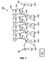
- FIG. 1 is a preferred embodiment of a designed as a printing press, processing machine according to the invention generally designated 100.
- a printing material for example paper 101
- the paper 101 is through as printing units 111, 112, 113, 114 formed clamping points and printed and output by a pull-out unit 115 again.
- the input, extraction and printing units 110 to 115 are positionable, in particular cylinder or angle correctable arranged.
- the printing units 111 to 114 are located in a web-tension-controlled area between the intake unit 110 and the extension unit 115.
- the printing units 111 to 114 each have a printing cylinder 111 'to 114', against which a respective impression roller 111 '' to 114 '' is made with strong pressure.
- the impression cylinders 111 'to 114' are individually and independently drivable.
- the associated drives 111 '' 'to 114' '' are shown schematically.
- the impression rollers 111 '' to 114 ''' are freely rotatable.
- the intake and exhaust units 110 and 115 respectively have two counter-rotating cylinders that guide the paper 101.
- the intake and the extension unit 110 and 115 are individually by a drive 110 '' 'and 115' '' driven.
- the feed and withdrawal unit 110, 115 and the printing units 111 to 114 together with the continuous paper 101 form a frictionally connected unit.
- the infeed 110, the extension unit 115 and the printing units 111 to 114 each represent a nip.
- the paper 101 is guided over unspecified explained roles, which are designated 102.
- rollers are provided with reference numeral 102. It may in particular be pulleys, drying, trimming equipment, etc.
- the web 101 is guided after a printing step in one of the printing units 111 to 114 via cooling rollers.
- a cooling roller 121 in the web section between the first printing unit 111 and the second printing unit 112
- a cooling roller 122 in the section between the third printing unit 113 and the fourth printing unit 114
- a cooling roller 123 and in the section between the fourth printing unit 114 and the extension unit 115
- a fourth cooling roller 124 is arranged.
- the cooling rollers 121 to 124 and the rollers 102 each have an effective moment of inertia, which adversely affects an acceleration phase of the printing press.
- all clamping points during an acceleration phase taking into account the modulus of elasticity of the material of the web and the effective moments of inertia of the cooling rollers 121 to 124 and the rollers 102 are piloted.
- the effective moments of inertia are determined beforehand, usually once, by means of a measuring run and a subsequent evaluation.
- the modulus of elasticity is determined automatically.
- a precontrol taking into account the modulus of elasticity, the effective moments of inertia and the acceleration is carried out.
- the precontrol can be carried out with dynamic timers, for example with the aid of a DT1 element (differentially delaying element), wherein T1 is chosen to be proportional to the track length / machine speed.
- the feedforward control can comprise additive angle values.
- the feed train 110 is detected and the subsequent printing unit 111 is moved by a predeterminable angle ⁇ .
- ⁇ It is preferably possible to make a setting by means of an angular movement in the position control.
- the angular movement can be carried out incrementally in small increments in order to prevent excessive stretching of the material into the plastic area.
- an adjustment can be carried out by means of an angular movement in the speed control.
- adjustment can be made by means of an angular movement in the torque control.
- the force .DELTA.F can be determined by means of a load cell (not shown) arranged in the web section between infeed unit 110 and first printing unit 111.
- the length l 0 and the area A of the web between the feed train 110th and the first printing unit 111 are known or can be measured in a simple manner.
- the change in length .DELTA.l can be determined as the product of angular displacement .DELTA..phi.
- the applied engine torque can be used as a force variable.
- friction effects on the other hand tensile forces outside the web tension path to be considered, since these each affect the applied engine torque. The latter can then be neglected if the material web outside of the two clamps clamping the web of material, in the selected example infeed unit 110 and first printing unit 111, is almost completely relaxed during the measurement. Otherwise, a web tension before or after the measuring section falsifies the web tension determined from the measured engine torque.
- the inertial masses are not known or are permanently stored in the acceleration compensation as constants, these can be determined with a known modulus of elasticity of the web by means of a measuring run, with two variants being proposed.
- the resulting web tension change for example by means of a load cell, can be determined during an acceleration phase.
- the effective inertia mass is then calculated with the aid of the known E modulus on the basis of the web tension change and the machine acceleration.
- the resulting register error can be determined.
- the resulting web tension change can be determined based on the registration error. Together with the machine acceleration, in turn, the effective inertial mass can be determined.
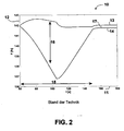
- FIG. 2 the course of a web tension in a dynamic case in the prior art is plotted against time in a diagram 10, in which two web tension curves 13 and 14 are shown.
- the web tension is plotted in the diagram 10 on a y-axis 12 against the time t on an x-axis 11.
- FIG. 2 shows the web tension curve in a dynamic case in which an acceleration of the rollers involved takes place.
- two web tension curves 13 and 14 are shown, which are to be assigned to different web tension subsections.
- a web tension section which is driven by a non-driven Axis, in the example shown a chill roll, is divided into two adjacent web tension subsections.
- a nip driven axis
- a driven pressure roller At the ends of the web tension section is in each case a nip (driven axis), in the example shown a driven pressure roller.
- a web tension section can be identified between the printing couple 112 and the printing couple 113, which is subdivided by the cooling roll 122 into two web tension subsections. It should be noted at this point that the figure according to FIG.
- FIG. 1 shows a printing machine according to the invention, in which both the modulus of elasticity of the material of the web and the effective moment of inertia of the cooling roller 122 is taken into account for a pilot control, whereas the FIG. 2 refers to a printing press, in which such a pilot control is not provided.
- the web tension in the region between a nip and a subsequent non-driven axis regularly has a lower value than in the area between said non-driven axis and a subsequent nip.
- an acceleration phase 15 For example, a dynamic force 16 corresponding to the difference of the web tension courses 13 and 14 is used to drive the non-driven roller.
- the web is accelerated within 30 s from 30 m / min to 200 m / min.
- the moment of inertia and the friction, ie the effective moment of inertia, the non-driven axles must be applied.
- the web tension drops behind a nip and rises before the subsequent nip, as the non-driven rollers are accelerated.
- a friction torque of the non-driven axle must be applied. This leads to a higher web tension behind a non-driven axle and the subsequent nip in the web path, since the nip has to exert a force to drive the non-driven axle. This force corresponds to a difference 17 between the illustrated web tension 13 and 14.
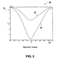
- FIG. 3 By way of example, a resulting register error is shown on a processing plant.
- a diagram 20 the course of a register deviation versus time is plotted, wherein two graphs 23 and 24 are shown, which are to be assigned to different moduli of elasticity.
- the register deviation is plotted in the diagram 20 on a y-axis 22 against the time t on an x-axis 21. It is an acceleration phase from 30 m / min to 250 m / min in 90 Seconds with materials with different modulus of elasticity.
- the acceleration as well as the effective moment of inertia to be considered are identical for both curves.
- the material of the web, which is associated with the curve 23, has an E-modulus of about 8.6 ⁇ 10 9 N / m 2 .
- the material of the web which is associated with the curve 24, has an E-modulus of about 3.6 ⁇ 10 9 N / m 2 . It is the different influence of the dynamic register error at the same moment of inertia of the non-driven rollers and the same acceleration clearly.
- FIG. 4 Finally, the curve 33 of a register error resulting from the use of the invention is shown on a processing unit.
- the register deviation is plotted on a y-axis 32 against the time t on a x-axis 31 in a diagram 30. It is an acceleration phase over 30 seconds shown. It becomes clear that the register deviation almost disappears.
Abstract
Description
Die vorliegende Erfindung betrifft ein Verfahren zur Achskorrektur bei einer Verarbeitungsmaschine sowie eine entsprechende Verarbeitungsmaschine, ein entsprechendes Computerprogramm sowie ein entsprechendes Computerprogrammprodukt.The present invention relates to a method for axis correction in a processing machine and a corresponding processing machine, a corresponding computer program and a corresponding computer program product.
Obwohl nachfolgend hauptsächlich auf Druckmaschinen Bezug genommen wird, ist die Erfindung nicht darauf beschränkt, sondern vielmehr auf alle Arten von Verarbeitungsmaschinen gerichtet, bei denen eine Warenbahn bzw. Materialbahn bearbeitet wird. Die Erfindung ist aber insbesondere bei Druckmaschinen wie z.B. Zeitungsdruckmaschinen, Akzidenzdruckmaschinen, Tiefdruckmaschinen, Inline-Flexodruckmaschinen, Verpackungsdruckmaschinen oder Wertpapierdruckmaschinen einsetzbar. Die Warenbahn kann aus Papier, Stoff, Pappe, Kunststoff, Metall, Gummi, in Folienform usw. ausgebildet sein.Although hereinafter mainly referred to printing presses, the invention is not limited thereto, but rather directed to all types of processing machines in which a web or material web is processed. However, the invention can be used in particular in printing presses such as, for example, newspaper printing presses, commercial printing machines, gravure printing machines, inline flexographic printing machines, packaging printing presses or securities printing machines. The web can be made of paper, cloth, cardboard, plastic, metal, rubber, in foil form, etc.
Stand der Technik Bei Verarbeitungsmaschinen, insbesondere Druckmaschinen, wird eine Warenbahn entlang von angetriebenen Achsen (Bahntransportachsen) wie z.B. Zugwalzen oder Vorschubwalzen und nicht angetriebenen Achsen wie z.B. Umlenk-, Leit-, Trocknungs- oder Kühlwalzen bewegt. Die Warenbahn wird gleichzeitig mittels meist ebenfalls angetriebener Bearbeitungsachsen bearbeitet, bspw. bedruckt, gestanzt, geschnitten, gefalzt usw.Background of the Invention In processing machines, in particular printing machines, a web of material is conveyed along driven axes (web transport axes), e.g. Pull rolls or feed rolls and non-driven axes such as e.g. Deflection, guide, drying or cooling rollers moved. The web is simultaneously processed by usually also driven processing axes, for example. Printed, stamped, cut, folded, etc.
Die Bahnspannung der Warenbahn wird über sog. Klemmstellen beeinflusst, die die Warenbahn reib-, form- oder kraftschlüssig einklemmen. Es handelt sich dabei regelmäßig um angetriebene Transport- oder Bearbeitungswerke. Bei einer Tiefdruckmaschine wird eine Klemmstelle üblicherweise durch ein Druckwerk, bei dem eine reibschlüssige Einheit zwischen dem angetriebenen Druckzylinder, dem Presseur und der Materialbahn besteht, gebildet. Die Warenbahn ist in Bahnspannungsabschnitte unterteilbar, wobei ein Bahnspannungsabschnitt von zwei Klemmstellen begrenzt wird. Innerhalb eines Bahnspannungsabschnitts können weitere angetriebene und/oder nicht angetriebene Achsen angeordnet sein.The web tension of the web is influenced by so-called. Clamps that clamp the web frictionally, positively or non-positively. These are usually driven transport or processing plants. In a gravure printing machine, a nip is usually formed by a printing unit, in which a frictional unit between the driven pressure cylinder, the impression roller and the material web consists. The web is subdivided into web tension sections, wherein a web tension section is limited by two terminal points. Within a web tension section, further driven and / or non-driven axles may be arranged.
Bei einer Beschleunigungs- bzw. Abbremsphase (Rotationsgeschwindigkeitsänderung) muss eine dynamische Kraft aufgewandt werden, um die nicht angetriebenen Achsen zu beschleunigen bzw. abzubremsen. Hierbei müssen das Trägheitsmoment und die Reibung der nicht angetriebenen Walzen aufgebracht werden.During an acceleration or deceleration phase (rotational speed change), a dynamic force must be used to accelerate or decelerate the non-driven axles. In this case, the moment of inertia and the friction of the non-driven rollers must be applied.
Üblicherweise werden die Maschinen bei niedriger Verarbeitungsgeschwindigkeit (Einrichtgeschwindigkeit) eingerichtet, um Makulatur zu minimieren. Durch die anschließende Beschleunigung bis zum Erreichen der Produktionsgeschwindigkeit kommt es zu Register- und Bahnspannungsabweichungen, die ausgeregelt werden müssen.Usually, the machines are set up at low processing speed (set-up speed) to minimize waste. The subsequent acceleration until the production speed is reached results in register and web voltage deviations which must be corrected.
Es ist bekannt, während der Hochlaufphase der von der Beschleunigung verursachten Dehnungsänderung mittels Winkelverstellung von Druckwerken entgegenzuwirken, wobei aufeinanderfolgende Druckwerke um ansteigende Winkel-Offsets vorgesteuert werden.It is known to counteract during the acceleration phase caused by the acceleration strain change by means of angular displacement of printing units, wherein successive printing units are precontrolled by increasing angle offsets.
Es ist möglich, die Winkel-Offsets durch Durchführung einer Messfahrt zu gewinnen. Dabei besteht jedoch der Nachteil, dass Makulatur erzeugt wird und Auswertungen des bei der Messfahrt beobachteten Registerfehlers durchgeführt werden müssen. Eine manuelle Auswertung ist fehleranfällig, eine automatische Auswertung ist aufgrund der notwendigen Sensorelemente aufwendig. Weiterhin ist die Durchführung einer Messfahrt relativ zeitaufwendig, da diese jeweils für alle auftretenden unterschiedlichen Beschleunigungsphasen durchgeführt werden muss.It is possible to obtain the angle offsets by performing a measuring run. However, there is the disadvantage that waste is generated and evaluations of the register error observed during the measurement run must be carried out. A manual evaluation is error-prone, an automatic evaluation is complicated due to the necessary sensor elements. Furthermore, the implementation of a test drive is relatively time-consuming, since this must be carried out for each occurring different acceleration phases.
Es ist außerdem möglich, die Vorsteuerwerte rechnerisch zu bestimmen, da diese proportional zur Massenträgheit der nicht angetriebenen Achsen, zum Kehrwert des Elastizitätsmoduls und zur Beschleunigung sind. Es ist bekannt, die Massenträgheit sowie den Elastizitätsmodul durch den Anwender manuell vorgeben zu lassen.It is also possible to computationally determine the precontrol values since these are proportional to the mass inertia of the non-driven axes, to the reciprocal of the modulus of elasticity and to the acceleration. It is known to manually set the mass inertia and the modulus of elasticity by the user.
Nachteilig an dieser Lösung gemäß dem Stand der Technik ist, dass bei der Vorgabe der Daten durch den Anwender einerseits Eingabefehler passieren können und andererseits notwendige Daten wie insbesondere der Elastizitätsmodul nicht immer genau bekannt sind.A disadvantage of this solution according to the prior art is that in the specification of the data by the user on the one hand input errors can happen and on the other hand necessary data such as in particular the modulus of elasticity are not always known exactly.
Es stellt sich daher die Aufgabe, eine verbesserte Achskorrektur während einer Beschleunigungs- oder Abbremsphase anzugeben.It is therefore the object to provide an improved axis correction during an acceleration or deceleration phase.
Diese Aufgabe wird gelöst durch ein Verfahren zur Achskorrektur gemäß Patentanspruch 1, eine Verarbeitungsmaschine gemäß Patentanspruch 8, ein Computerprogramm gemäß Patentanspruch 14 sowie ein Computerprogrammprodukt gemäß Patentanspruch 15. Vorteilhafte Weiterbildungen sind Gegenstand der Unteransprüche sowie der nachfolgenden Beschreibung.This object is achieved by a method for axis correction according to
Bei einem erfindungsgemäßen Verfahren zur Achskorrektur, wodurch insbesondere eine Bahnspannungs- und/oder Registerregelung oder -einstellung erfolgt, erfolgt während einer Rotationsgeschwindigkeitsänderung einer einen Bahnspannungsabschnitt begrenzenden Klemmstelle eine Vorsteuerung dieser den Bahnspannungsabschnitt begrenzenden Klemmstelle und/oder einer in diesem Bahnspannungsabschnitt vorhandenen Bearbeitungsachse unter Berücksichtigung des Elastizitätsmoduls des Materials der Warenbahn und eines Trägheitsmomentes wenigstens einer in diesem Bahnspannungsabschnitt vorhandenen nicht angetriebenen Achse, wobei der Elastizitätsmodul des Materials der Warenbahn automatisch bestimmt wird. Eine Möglichkeit zur Bestimmung des Elastizitätsmoduls des Materials einer Warenbahn wird beispielsweise in der
Durch die erfindungsgemäße Achskorrektur, insbesondere Bahnspannungsregelung und/oder Registerregelung, unter Berücksichtigung des Elastizitätsmoduls des Materials der Warenbahn und eines Trägheitsmomentes wenigstens einer in einem Bahnspannungsabschnitt vorhandenen nicht angetriebenen Achse bei automatischer Bestimmung des Elastizitätsmodul des Materials der Warenbahn können die Nachteile des Standes der Technik vermindert werden.Due to the inventive axis correction, in particular web tension control and / or register control, taking into account the modulus of elasticity of the material of the web and an inertial moment of at least one non-driven axis present in a web tension section with automatic determination of the modulus of elasticity of the material of the web, the disadvantages of the prior art can be reduced ,
Vorteilhafterweise müssen keine produktionsabhängigen Materialdaten eingegeben bzw.. durch Abruf früherer Produktionen bekannt gemacht werden, da die Daten selbständig bzw. automatisch ermittelt werden können. Es ist möglich, die Bestimmung der Einstellungen der Beschleunigungskompensation im Stillstand der Maschine durchzuführen, wobei keine Makulatur erzeugt wird.Advantageously, no production-dependent material data must be entered or made known by retrieving earlier productions, since the data can be determined independently or automatically. It is possible to carry out the determination of the settings of the acceleration compensation when the machine is at a standstill, whereby no waste is generated.
Die erfindungsgemäße Vorsteuerung stellt eine deutliche Verbesserung gegenüber dem Stand der Technik dar, da nun eine prädiktive Vorsteuerung der zu erwartenden Fehler bereitgestellt werden kann, statt auf einen bereits aufgetretenen Fehler reagieren zu müssen. Durch die Achskorrektur im Sinne einer Bahnspannungseinstellung bzw. -regelung werden Bahnspannungsänderungen einer Beschleunigungs- oder Abbremsphase verringert, was sich unmittelbar in einer Reduzierung des Ausschusses niederschlägt. Durch die geringeren Bahnspannungsänderungen werden ebenfalls Registerabweichungen verringert, welche durch die ebenfalls beschriebene Achskorrektur im Sinne einer Registerregelung bzw. -steuerung weiter verringert werden. Aufgrund der zusätzlichen Vorsteuerung können effektivere Regelstrategien entworfen werden, da eine größere Einflussnahme auf die Warenbahn möglich ist. Hat beispielsweise die Druckmaschine den eingeschwungenen Zustand erreicht, können Längsregisterabweichungen mittels stationärer Regelstrategien, in die die Vorsteuerung einbezogen wird, schneller ausgeregelt werden. Befindet sich die Maschine in einer dynamischen Übergangsphase, beispielsweise durch Änderungen des Sollwerts der Bahnspannung oder der Bahngeschwindigkeit in der Maschine, ermöglicht die Vorsteuerung eine schnellere dynamische Registerregelung.The pilot control according to the invention represents a significant improvement over the prior art, since now a predictive feedforward control of the expected error can be provided instead of having to react to an error that has already occurred. Due to the axis correction in the sense of a web tension adjustment or regulation, web tension changes of an acceleration or deceleration phase are reduced, which directly translates into a reduction of the reject. Due to the lower web tension changes register deviations are also reduced, which by the also described Axis correction in terms of register control or control can be further reduced. Due to the additional pre-control, more effective control strategies can be designed, since greater influence on the material web is possible. If, for example, the printing press has reached the steady state, longitudinal register deviations can be compensated more quickly by means of stationary control strategies, in which the feedforward control is included. If the machine is in a dynamic transitional phase, such as changes in the train tension setpoint or web speed in the machine, the feedforward control provides faster dynamic register control.
Durch die erfindungsgemäße Maßnahme wird eine stärkere Entkopplung der Warenbahn bei Register- und/oder Bahnspannungsregelungen erreicht und der Einfluss der Trägheits- und Reibmomente der nicht angetriebenen Achsen gesenkt. Der stationäre und dynamische Fehler zwischen den einzelnen Verarbeitungs- bzw. Druckwerken nimmt ab. Darüber hinaus kann eine schnellere Ausregelung von Registerfehlern erfolgen. Die Rückwirkung einer Beschleunigungs- oder Abbremsphase auf die Bahnspannung wird vermindert, was insbesondere schnellere bzw. dynamischere Beschleunigungs- oder Abbremsvorgänge möglich macht. Insgesamt wird Ausschuss bzw. Makulatur deutlich vermindert, was unter anderem zu einer Senkung der Produktionskosten führt.The inventive measure a greater decoupling of the web is achieved in register and / or web tension controls and lowered the influence of the inertia and friction moments of the non-driven axles. The stationary and dynamic error between the individual processing or printing units decreases. In addition, a faster compensation of register errors can take place. The retroactive effect of an acceleration or deceleration phase on the web tension is reduced, which makes possible in particular faster or more dynamic acceleration or deceleration processes. Overall, waste or waste is significantly reduced, which among other things leads to a reduction in production costs.
Vorteilhafterweise erfolgt die Vorsteuerung aller betroffenen Achsen des Bahnspannungsabschnittes. Insbesondere wird zur Regelung bzw. Einstellung der Bahnspannung in einem Bahnspannungsabschnitt eine Vorsteuerung der den Bahnspannungsabschnitt begrenzenden Klemmstellen und zur Regelung bzw. Einstellung des Registers einer Bearbeitungsachse innerhalb eines Bahnspannungsabschnitts eine Vorsteuerung der Bearbeitungsachse und/oder der den Bahnspannungsabschnitt begrenzenden Klemmstellen durchgeführt.Advantageously, the pilot control of all affected axes of the web tension section takes place. In particular, for controlling or adjusting the web tension in a web tension section, a feedforward of the web tension section limiting clamping points and for controlling or setting the register of a processing axis within a web tension section a pre-control of the machining axis and / or the web tension limiting terminal points performed.
Typischerweise werden bei Bahntransportachsen oder bei Bearbeitungsachsen additive Geschwindigkeiten, multiplikative Geschwindigkeitsfaktoren (sogenannter Feinabgleich, Getriebefaktoren) und/oder additive Winkel-Offsets vorgesteuert.Typically, in the case of web transport axes or machining axes, additive velocities, multiplicative velocity factors (so-called fine adjustment, gear ratios) and / or additive angle offsets are precontrolled.
Vorteilhafterweise beinhalten die zu berücksichtigen effektiven Trägheitsmomente auch die Reibmomente der Achsen. Die effektiven Trägheitsmomente der nicht angetriebenen Achsen können insbesondere durch eine Messfahrt ermittelt werden.
Dabei kann aus einer Auswertung der Registerfehler der Produkte auf die effektiven Trägheitsmomente der nicht angetriebenen Achsen zurückgerechnet werden. Ebenso kann eine Online-Auswertung der gemessenen Registerfehler durchgeführt werden. Neben der Ermittlung durch Messfahrt ist ebenfalls eine Ermittlung durch ein Online-Beobachtung der aufgetretenen Registerfehler sowie eine darauf basierende Schätzung der Trägheitsmomente beispielsweise mittels Modellfolgeregelung, Beobachter, Kalman-Filterung usw. möglich. Schließlich kann das Trägheitsmoment ebenfalls bei Kenntnis der mechanischen Parameter wie z.B. Durchmesser, Material, Materialverteilung usw. der nicht angetriebenen Achsen berechnet werden. Da sich der mechanische Aufbau einer Verarbeitungsmaschine üblicherweise nicht oder nur selten ändert, ist die Bestimmung der Trägheitsmomente nur einmalig bzw. selten nötig. Die bestimmten Werte werden dann gespeichert und können für alle nachfolgenden Produktionen verwendet werden.Advantageously, the moment of inertia to be considered also include the friction moments of the axes. The effective moments of inertia of the non-driven axles can be determined in particular by a measuring run.
It can be calculated back from an evaluation of the register error of the products on the effective moments of inertia of the non-driven axles. Likewise, an online evaluation of the measured register errors can be carried out. In addition to the determination by test drive is also a determination by an online observation of the register errors occurred as well as an estimate based on the moments of inertia, for example by means of model following, observers, Kalman filtering, etc. possible. Finally, the moment of inertia can also be calculated knowing the mechanical parameters such as diameter, material, material distribution, etc. of the non-driven axes. Since the mechanical structure of a processing machine usually does not or only rarely changes, the determination of the moments of inertia is only once or rarely necessary. The specific values will be then saved and can be used for all subsequent productions.
Vorteilhafterweise erfolgt die Vorsteuerung unter Berücksichtigung des jeweiligen (effektiven) Trägheitsmomentes aller in einem Bahnspannungsabschnitt vorhandenen nicht angetriebenen Achsen. Damit kann die Qualität der Vorsteuerung weiter erhöht werden.Advantageously, the precontrol takes place taking into account the respective (effective) moment of inertia of all non-driven axes present in a web tension section. Thus, the quality of the feedforward control can be further increased.
Bevorzugterweise werden die jeweiligen Trägheitsmomente aller in diesem Bahnspannungsabschnitt vorhandenen nicht angetriebenen Achsen zu einem für diesen Bahnspannungsabschnitt zu berücksichtigen Gesamtträgheitsmoment konzentriert. Es handelt sich dabei um eine einfach durchzuführende und dennoch gute Ergebnisse liefernde Maßnahme. Durch eine fiktive "Schwerpunktsbildung" ist nur mehr ein Gesamtträgheitsmoment zu berücksichtigen. Dieses Gesamtträgheitsmoment kann beispielsweise auf eine der oben genannten Arten (Messfahrt usw.) ermittelt werden.Preferably, the respective moments of inertia of all non-driven axles present in this web tension section are concentrated to a total moment of inertia to be considered for this web tension section. It is an easy-to-perform, yet good-results measure. By a fictional "emphasis" is only a total moment of inertia to consider. This total moment of inertia can be determined, for example, in one of the above-mentioned ways (test drive, etc.).
Es ist besonders zweckmäßig, wenn Vorsteuerwerte für die Vorsteuerung der Klemmstelle und/oder der Bearbeitungsachse zur Entkopplung an Klemmstellen und/oder Bearbeitungsachsen benachbarter Bahnspannungsabschnitte statisch und/oder dynamisch kaskadiert werden. Die Kaskadierung kann mit unterschiedlichen Faktoren, beispielsweise invers, proportional, anteilig oder dynamisch usw., erfolgen, um benachbarte Bahnspannungsabschnitte von der Vorsteuerung in dem betreffenden Bahnspannungsabschnitt zu entkoppeln.It is particularly expedient if precontrol values for the precontrol of the clamping point and / or the machining axis for decoupling at clamping points and / or machining axes of adjacent web tension sections are statically and / or dynamically cascaded. The cascading can take place with different factors, for example inverse, proportional, proportionate or dynamic, etc., in order to decouple adjacent web tension sections from the precontrol in the relevant web tension section.
Ebenso vorteilhaft erfolgt die Vorsteuerung zusätzlich unter Berücksichtigung der Rotationsgeschwindigkeitsänderung der Klemmstelle. Da der zu erwartende Fehler proportional zur auftretenden Rotationsgeschwindigkeitsänderung, d.h. positive oder negative Beschleunigung der Achse, ist, wird diese Beschleunigung vorteilhaft ebenfalls bei der Vorsteuerung berücksichtigt. Die Beschleunigung kann beispielsweise durch Ableitung bestimmter Geberwerte, beispielsweise zweimaliger Ableitung der Lagegeberwerte oder einmaliger Ableitung der Geschwindigkeitsgeberwerte bestimmt werden. Für die Lage- oder Geschwindigkeitsmessung kann beispielsweise eine Abtastung von auf der Warenbahn aufgedruckten Informationen wie z.B. Marken, Lochung usw. erfolgen. Ebenfalls ist die Bestimmung mittels eines Beschleunigungsgebers möglich. In Frage kommen weiterhin die Übertragung der Werte von der Maschinensteuerung zur Recheneinheit für die Bahnspannungsregelung bzw. Registerregelung z.B. mittels Feldbus-Kommunikation, wobei z.B. eine Soll-Position, Soll-Geschwindigkeit, Soll-Beschleunigung, Soll-Ruck, Ist-Position, Ist-Geschwindigkeit, Ist-Beschleunigung oder Ist-Ruck der Maschinen-Leitposition übertragen werden können. Auch ist eine Übertragung binärer Signale, die eine Geschwindigkeitsänderung anzeigen, von der Maschinensteuerung zur Recheneinheit für die Bahnspannungs- bzw. Registerregelung sowie die Kenntnis fest vorgegebener Rucke bzw. Beschleunigungswerte in der Recheneinheit für die Bahnspannungs- bzw. Registerregelung möglich. Schließlich kann eine Schätzung der Beschleunigung anhand weiterer Prozessgrößen wie z.B. der Antriebsmomente erfolgen.Likewise advantageously, the precontrol is additionally taking into account the rotation speed change the nip. Since the expected error is proportional to the occurring rotational speed change, ie positive or negative acceleration of the axis, this acceleration is advantageously also taken into account in the pilot control. The acceleration can be determined, for example, by deriving certain transmitter values, for example two times the derivative of the position encoder values or a one-time derivative of the speed sensor values. For the position or speed measurement, for example, a scan of printed on the web information such as brands, perforation, etc. take place. Also, the determination by means of an accelerator is possible. Also suitable are the transmission of the values from the machine control to the processing unit for the web tension control or register control, for example by means of fieldbus communication, where, for example, a setpoint position, setpoint speed, setpoint acceleration, setpoint jerk, actual position, actual position Speed, actual acceleration or actual jerk of the machine master position can be transmitted. Also possible is a transmission of binary signals which indicate a change in speed, from the machine control to the arithmetic unit for the web tension or register control and the knowledge of fixed jerk or acceleration values in the arithmetic unit for the web tension or register control. Finally, an estimate of the acceleration based on other process variables such as the drive torque can be done.
Die Recheneinheit der erfindungsgemäßen Verarbeitungsmaschine ist in vorteilhafter Weiterbildung dazu eingerichtet, die vorangehend beschriebenen Schritte durchzuführen.The arithmetic unit of the processing machine according to the invention is set up in an advantageous development to carry out the steps described above.
Zweckmäßigerweise sind bei einer erfindungsgemäßen Verarbeitungsmaschine die Recheneinheit und die Bewegungssteuerung (Motion Control) der antriebseigenen Achsen und/oder die Maschinenablaufsteuerung in einer gemeinsamen Steuerungshardware integriert ausgebildet. Derartige Verarbeitungsmaschinen sind in kompakter Form bereitstellbar und bieten eine vereinfachte Handhabung, da keine Kombination mit externen Komponenten erforderlich ist.Appropriately, in a processing machine according to the invention, the arithmetic unit and the motion control (motion control) of the drive's own axes and / or the machine sequence control are integrated in a common control hardware. Such processing machines are available in a compact form and offer a simplified handling, since no combination with external components is required.
Die Erfindung betrifft zudem ein Computerprogramm mit Programmcodemitteln, um alle Schritte eines erfindungsgemäßen Verfahrens durchzuführen, wenn das Computerprogramm auf einem Computer oder einer entsprechenden Recheneinheit, insbesondere in einer erfindungsgemäßen Verarbeitungsmaschine, ausgeführt wird.The invention additionally relates to a computer program with program code means in order to carry out all the steps of a method according to the invention when the computer program is executed on a computer or a corresponding arithmetic unit, in particular in a processing machine according to the invention.
Das erfindungsgemäß vorgesehene Computerprogrammprodukt mit Programmcodemitteln, die auf einem computerlesbaren Datenträger gespeichert sind, ist zum Durchführen aller Schritte eines Verfahrens ausgebildet, wenn das Computerprogramm auf einem Computer oder einer entsprechenden Recheneinheit, insbesondere in einer Verarbeitungsmaschine, ausgeführt wird. Geeignete Datenträger sind insbesondere Disketten, Festplatten, Flash-Speicher, EEPROMs, CD-ROMs, DVDs u.a.m. Auch ein Download eines Programms über Computernetze (Internet, Intranet usw.) ist möglich.The inventively provided computer program product with program code means which are stored on a computer-readable data carrier is designed to perform all the steps of a method when the computer program is executed on a computer or a corresponding computing unit, in particular in a processing machine. Suitable data carriers are, in particular, floppy disks, hard disks, flash memories, EEPROMs, CD-ROMs, DVDs and the like. It is also possible to download a program via computer networks (Internet, intranet, etc.).
Weitere Vorteile und Ausgestaltungen der Erfindung ergeben sich aus der Beschreibung und der beiliegenden Zeichnung.Further advantages and embodiments of the invention will become apparent from the description and the accompanying drawings.
Es versteht sich, dass die vorstehend genannten und die nachstehend noch zu erläuternden Merkmale nicht nur in der jeweils angegebenen Kombination, sondern auch in anderen Kombinationen oder in Alleinstellung verwendbar sind, ohne den Rahmen der vorliegenden Erfindung zu verlassen.It is understood that the features mentioned above and those yet to be explained not only in the each combination specified, but also in other combinations or alone, without departing from the scope of the present invention.
Die Erfindung ist anhand eines Ausführungsbeispiels in der Zeichnung schematisch dargestellt und wird im folgenden unter Bezugnahme auf die Zeichnung ausführlich beschrieben.The invention is illustrated schematically with reference to an embodiment in the drawing and will be described below in detail with reference to the drawings.
- Figur 1FIG. 1
- zeigt eine schematische Darstellung einer bevorzugten Ausführungsform einer als Druckmaschine ausgebildeten erfindungsgemäßen Verarbeitungsmaschine;shows a schematic representation of a preferred embodiment of a machine according to the invention designed as a printing machine;
- Figur 2FIG. 2
- zeigt schematisch eine Abhängigkeit einer Bahnspannung von der Zeit in einem dynamischen Fall im Stand der Technik;schematically shows a dependence of a web tension on time in a dynamic case in the prior art;
- Figur 3FIG. 3
- zeigt schematisch eine Abhängigkeit einer Registerabweichung von der Zeit in einem dynamischen Fall im Stand der Technik; undschematically shows a dependence of a register deviation of time in a dynamic case in the prior art; and
- Figur 4FIG. 4
- zeigt schematisch eine Abhängigkeit einer Registerabweichung von der Zeit bei einer bevorzugten Ausgestaltung der Erfindung.schematically shows a dependence of a register deviation of time in a preferred embodiment of the invention.
In
Die Druckwerke 111 bis 114 weisen jeweils einen Druckzylinder 111' bis 114' auf, gegen den jeweils ein Presseur 111'' bis 114'' mit starkem Druck angestellt ist. Die Druckzylinder 111' bis 114' sind einzeln und unabhängig antreibbar. Die zugehörigen Antriebe 111''' bis 114''' sind schematisch dargestellt. Die Presseure 111'' bis 114'' sind frei drehbar ausgebildet. Das Einzugs- und Auszugswerk 110 bzw. 115 weisen jeweils zwei gegenläufige Zylinder auf, die das Papier 101 führen. Auch das Einzugs- und das Auszugswerk 110 bzw. 115 sind einzeln durch einen Antrieb 110''' bzw. 115''' antreibbar. Das Einzugs- und Auszugswerk 110, 115 und die Druckwerke 111 bis 114 bilden jeweils zusammen mit dem durchlaufenden Papier 101 eine reibschlüssig verbundene Einheit. Das Einzugswerk 110, das Auszugswerk 115 sowie die Druckwerke 111 bis 114 stellen jeweils eine Klemmstelle dar.The
In den Bahnabschnitten zwischen den einzelnen Druckwerken 111 bis 114 wird das Papier 101 über nicht näher erläuterte Rollen geführt, die mit 102 bezeichnet sind. Aus Gründen der Übersichtlichkeit sind nicht alle Rollen mit Bezugszeichen 102 versehen. Es kann sich insbesondere um Umlenkrollen, Trocknungs-, Beschneideeinrichtungen usw. handeln.In the web sections between the
Die Bahn 101 wird nach einem Bedruckschritt in einem der Druckwerke 111 bis 114 über Kühlwalzen geführt. Dazu ist im Bahnabschnitt zwischen dem ersten Druckwerk 111 und dem zweiten Druckwerk 112 eine Kühlwalze 121, im Abschnitt zwischen dem zweiten Druckwerk 112 und dem dritten Druckwerk 113 eine Kühlwalze 122, im Abschnitt zwischen dem dritten Druckwerk 113 und dem vierten Druckwerk 114 eine Kühlwalze 123 und im Abschnitt zwischen dem vierten Druckwerk 114 und dem Auszugswerk 115 eine vierte Kühlwalze 124 angeordnet.The
Die Kühlwalzen 121 bis 124 sowie die Rollen 102 weisen jeweils ein effektives Trägheitsmoment auf, das eine Beschleunigungsphase der Druckmaschine negativ beeinflusst. Gemäß der dargestellten bevorzugten Ausführungsform einer Druckmaschine werden sämtliche Klemmstellen während einer Beschleunigungsphase unter Berücksichtigung des Elastizitätsmoduls des Materials der Warenbahn sowie der effektiven Trägheitsmomente der Kühlwalzen 121 bis 124 und der Rollen 102 vorgesteuert. Die effektiven Trägheitsmomente werden zuvor, üblicherweise einmalig, mittels einer Messfahrt und einer anschließenden Auswertung ermittelt. Der Elastizitätsmodul wird automatisch bestimmt. Bei einer Beschleunigungsphase wird eine den Elastizitätsmodul, die effektiven Trägheitsmomente sowie die Beschleunigung berücksichtigende Vorsteuerung durchgeführt. Dabei kann die Vorsteuerung mit dynamischen Zeitgliedern beispielsweise mit Hilfe eines DT1-Gliedes (differenzierend verzögerndes Glied) durchgeführt werden, wobei T1 proportional zu Bahnlänge/Maschinengeschwindigkeit gewählt wird. Die Vorsteuerung kann additive Winkelwerte umfassen. Als Resultat erhält man einen annähernd konstanten Verlauf der Bahnspannung in einem gewünschten Abschnitt der Warenbahn und daraus folgend eine annähernd verschwindende Registerabweichung, wie es anhand
Nachfolgend wird anhand
Der Elastizitätsmodul E lässt sich berechnen zu E = (ΔF·l0)/(A·Al) mit ΔF: aufgewandte Kraft;·l0: ursprüngliche Länge; A: Fläche der Materialbahn; Δl: erzielte Längenänderung. Die Kraft ΔF ist mittels einer im Bahnabschnitt zwischen Einzugswerk 110 und erstem Druckwerk 111 angeordneten Kraftmessdose (nicht gezeigt) bestimmbar. Die Länge l0 sowie die Fläche A der Warenbahn zwischen dem Einzugswerk 110 und dem ersten Druckwerk 111 sind bekannt oder können auf einfache Weise gemessen werden. Schließlich ist die Längenänderung Δl als Produkt von Winkelverstellung Δϕ und Radius der Druckwalze oder und mittels eines Lagegebers (z.B. des Motorgebers) bestimmbar. Alternativ kann eine Spannungsänderung auch durch Vorgabe einer Bahnspannung mittels der Kraft einer Tänzerwalze im Einzugs- und/oder Auszugswerk herbeigeführt werden. Sofern ein Tänzer im Einzugs- oder Auszugswerk vorhanden ist, kann mit der Vorgabe des Tänzerdrucks eine Kraft in die Warenbahn eingeprägt werden. Diese eingeprägte Kraft ergibt dann eine Bahnspannung. Ebenfalls kann die Vorgabe einer Bahnspannung mittels einer Vorgabe einer Kraft eines nicht komplett angestellten Presseurs erfolgen. Wenn der Presseur angestellt wird, kann durch die Umschlingung auch eine Bahnspannung eingeprägt werden. Mit den erhaltenen Daten lässt sich schließlich eine produktionsabhängige Konstante k = EA bestimmen.The elastic modulus E can be calculated as E = (ΔF · l 0 ) / (A · Al) with ΔF: applied force; · l 0 : original length; A: surface of the material web; Δl: achieved change in length. The force .DELTA.F can be determined by means of a load cell (not shown) arranged in the web section between
Alternativ kann z.B. statt der Messung mittels einer (vorhandenen) Kraftmessdose das aufgewandte Motormoment als Kraftgröße herangezogen werden. Hierbei sind einerseits Reibungseffekte, andererseits Zugkräfte außerhalb der Bahnspannungsstrecke zu berücksichtigen, da diese jeweils das aufgewandte Motormoment beeinflussen. Letztere können dann vernachlässigt werden, wenn die Materialbahn außerhalb der beiden die Materialbahn einklemmenden Klemmstellen, im gewählten Beispiel Einzugswerk 110 und erstes Druckwerk 111, während der Messung fast komplett entspannt ist. Ansonsten verfälscht eine Bahnspannung vor bzw. hinter dem Messabschnitt die aus dem gemessenen Motormoment ermittelte Bahnspannung.Alternatively, for example, instead of the measurement by means of a (existing) load cell, the applied engine torque can be used as a force variable. In this case, on the one hand friction effects, on the other hand tensile forces outside the web tension path to be considered, since these each affect the applied engine torque. The latter can then be neglected if the material web outside of the two clamps clamping the web of material, in the selected
Im folgenden wird nun ebenfalls beispielhaft eine Möglichkeit zur Bestimmung der Trägheitsmassen offenbart. Sofern die Trägheitsmassen nicht bekannt sind bzw. fest in der Beschleunigungskompensation als Konstanten hinterlegt sind, können diese bei bekanntem E-Modul der Warenbahn mittels einer Messfahrt ermittelt werden, wobei zwei Varianten vorgeschlagen werden. Einerseits kann während einer Beschleunigungsphase die sich ergebende Bahnspannungsänderung, beispielsweise mittels einer Kraftmessdose, bestimmt werden. Anhand dieser Messung wird dann bei bekanntem E-Modul anhand der Bahnspannungsänderung und der Maschinenbeschleunigung die effektive Trägheitsmasse berechnet. Andererseits kann während einer Beschleunigungsphase der sich ergebende Registerfehler bestimmt werden. Bei bekanntem E-Modul kann anhand des Registerfehlers die sich ergebende Bahnspannungsänderung bestimmt werden. Zusammen mit der Maschinenbeschleunigung ist wiederum die effektive Trägheitsmasse bestimmbar.In the following, a possibility for determining the inertial masses will also be disclosed by way of example. If the inertial masses are not known or are permanently stored in the acceleration compensation as constants, these can be determined with a known modulus of elasticity of the web by means of a measuring run, with two variants being proposed. On the one hand, the resulting web tension change, for example by means of a load cell, can be determined during an acceleration phase. On the basis of this measurement, the effective inertia mass is then calculated with the aid of the known E modulus on the basis of the web tension change and the machine acceleration. On the other hand, during an acceleration phase, the resulting register error can be determined. With a known modulus of elasticity, the resulting web tension change can be determined based on the registration error. Together with the machine acceleration, in turn, the effective inertial mass can be determined.
In
In dem Diagramm 10 sind zwei Bahnspannungsverläufe 13 und 14 dargestellt, die verschiedenen Bahnspannungsunterabschnitten zuzuordnen sind. Betrachtet wird dabei ein Bahnspannungsabschnitt, der von einer nicht angetriebenen Achse, im abgebildeten Beispiel einer Kühlwalze, in zwei aneinandergrenzende Bahnspannungsunterabschnitte unterteilt wird. An den Enden des Bahnspannungsabschnitts befindet sich jeweils eine Klemmstelle (angetriebene Achse), im abgebildeten Beispiel eine angetriebene Druckwalze. Unter Bezugnahme auf
Dem Verlauf der Warenbahn folgend, befindet sich der Bahnspannungsunterabschnitt, dem der Bahnspannungsverlauf 14 zuzuordnen ist, zwischen einer Klemmstelle und einer nicht angetriebenen Achse, und der Bahnspannungsunterabschnitt, dem der Bahnspannungsverlauf 13 zuzuordnen ist, direkt anschließend im Warenbahnverlauf zwischen der genannten nicht angetriebenen Achse und einer nachfolgenden Klemmstelle.Following the course of the web, there is the web tension subsection to which the
Wie aus dem Diagrammen 10 ersichtlich ist, weist die Bahnspannung im Bereich zwischen einer Klemmstelle und einer nachfolgenden nicht angetriebenen Achse regelmäßig einen geringeren Wert als im Bereich zwischen der genannten nicht angetriebenen Achse und einer nachfolgenden Klemmstelle auf.As can be seen from the diagrams 10, the web tension in the region between a nip and a subsequent non-driven axis regularly has a lower value than in the area between said non-driven axis and a subsequent nip.
Bei einer Beschleunigungsphase 15 gemäß
Nach der Beschleunigung stellt sich ein stationärer Zustand ein, der in
In
In
Es versteht sich, dass in den dargestellten Figuren nur eine besonders bevorzugte Ausführungsform der Erfindung dargestellt ist. Daneben ist jede andere Ausführungsform denkbar, ohne den Rahmen dieser Erfindung zu verlassen.It is understood that in the illustrated figures, only a particularly preferred embodiment of the invention is shown. In addition, any other embodiment is conceivable without departing from the scope of this invention.
Bezugszeichenliste
- 100
- Druckmaschine
- 101
- Papier
- 102
- Rolle
- 110
- Einzugswerk
- 110'''
- Antrieb
- 111, 112, 113, 114
- Druckwerk
- 111', 112', 113', 114'
- Druckzylinder
- 111'', 112'', 113'', 114''
- Presseur
- 111''', 112''', 113''', 114'''
- Antrieb
- 115
- Auszugswerk
- 115'''
- Antrieb
- 121, 122, 123, 124
- Kühlwalze
- 10, 20, 30
- Diagramm
- 11, 21, 31
- x-Achse
- 12, 22, 32
- y-Achse
- 13, 14
- Bahnspannungskurve
- 15, 25
- Beschleunigungsphase
- 16, 17, 26
- - Kraft
- 23, 24, 33
- Registerabweichungskurve
- 100
- press
- 101
- paper
- 102
- role
- 110
- infeed
- 110 '''
- drive
- 111, 112, 113, 114
- printing unit
- 111 ', 112', 113 ', 114'
- pressure cylinder
- 111 '', 112 '', 113 '', 114 ''
- impression roller
- 111 ''',112''', 113 ''',114'''
- drive
- 115
- excerpt
- 115 '''
- drive
- 121, 122, 123, 124
- chill roll
- 10, 20, 30
- diagram
- 11, 21, 31
- X axis
- 12, 22, 32
- y-axis
- 13, 14
- Web tension curve
- 15, 25
- acceleration phase
- 16, 17, 26
- - Force
- 23, 24, 33
- Register deviation curve
Claims (15)
wobei die Warenbahn (101) in wenigstens einen Bahnspannungsabschnitt unterteilbar ist, wobei ein Bahnspannungsabschnitt von zwei als angetriebene Transport- oder Bearbeitungsachsen ausgebildeten Klemmstellen (110-115) begrenzt wird,
wobei während einer Rotationsgeschwindigkeitsänderung einer einen Bahnspannungsabschnitt begrenzenden Klemmstelle (110-115) eine Vorsteuerung dieser den Bahnspannungsabschnitt begrenzenden Klemmstelle (110-115) und/oder einer in diesem Bahnspannungsabschnitt vorhandenen-Bearbeitungsachse (111-114) unter Berücksichtigung des Elastizitätsmoduls des Materials der Warenbahn und eines Trägheitsmomentes wenigstens einer in diesem Bahnspannungsabschnitt vorhandenen nicht angetriebenen Achse (102, 121-124) erfolgt, wobei der Elastizitätsmodul des Materials der Warenbahn (101) automatisch bestimmt wird.Method for correcting the axis in a processing machine (100) which has at least two driven transport axes (110, 115), at least one non-driven or driven machining axis (111, 112, 113, 114) and at least one for transporting and processing a material web (101) further non-driven axle (102, 121, 122, 123, 124),
wherein the web (101) is subdivided into at least one web tension section, wherein a web tension section is bounded by two clamping points (110-115) designed as driven transport or machining axes,
wherein during a rotation speed change of a web tension limiting clamping point (110-115) precontrol of this web tension limiting clamping point (110-115) and / or existing in this web tensioning machining axis (111-114) taking into account the modulus of elasticity of the material of the web and an inertial moment of at least one non-driven axis (102, 121-124) present in this web tension section takes place, the modulus of elasticity of the material of the web (101) being determined automatically.
wobei die Verarbeitungsmaschine (100) eine Recheneinheit (200) aufweist, die dazu eingerichtet ist, den Elastizitätsmodul des Materials der Warenbahn zu bestimmen und während einer Rotationsgeschwindigkeitsänderung einer einen Bahnspannungsabschnitt begrenzenden Klemmstelle (110-115) eine Vorsteuerung dieser den Bahnspannungsabschnitt begrenzenden Klemmstelle (110-115) und/oder einer in diesem Bahnspannungsabschnitt vorhandenen Bearbeitungsachse (111-114) mittels Vorsteuerwerten unter Berücksichtigung des bestimmten Elastizitätsmoduls des Materials der Warenbahn (101) und eines Trägheitsmomentes wenigstens einer in diesem Bahnspannungsabschnitt vorhandenen nicht angetriebenen Achse (102, 121-124) durchzuführen.Processing machine (100) for the transport and processing of a web (101) at least two driven transport axes (110-115), at least one non-driven or driven machining axis (111-114) and at least one further non-driven axle (102, 121-124), wherein the web (101) is subdivided into at least one web tension section, wherein a web tension section is bounded by two clamping points (110-115) designed as driven transport or machining axes,
wherein the processing machine (100) has a computation unit (200) which is set up to determine the modulus of elasticity of the material of the material web and during a rotational speed change of a clamping point delimiting a web tension section (110-115) a precontrol of this clamping point bounding the web tension section (110- 115) and / or a machining axis (111-114) present in this web tension section by means of precontrol values taking into account the determined modulus of elasticity of the material of the web (101) and an inertial moment of at least one non-driven axle (102, 121-124) present in said web tension section ,
wobei die Recheneinheit (200) dazu eingerichtet ist, die Vorsteuerwerte unter Berücksichtigung des jeweiligen Trägheitsmomentes aller in diesem Bahnspannungsabschnitt vorhandenen nicht angetriebenen Achsen (102, 121-124) zu ermitteln, insbesondere die jeweiligen Trägheitsmomente aller in diesem Bahnspannungsabschnitt vorhandenen nicht angetriebenen Achsen (102, 121-124) zu einem für diesen Bahnspannungsabschnitt zu berücksichtigen Gesamtträgheitsmoment zu konzentrieren.Processing machine (100) according to claim 8 or 9,
wherein the arithmetic unit (200) is adapted to determine the precontrol values taking into account the respective moment of inertia of all non-driven axles (102, 121-124) present in this web tension section, in particular the respective moments of inertia of all concentrate in this web tension section existing non-driven axles (102, 121-124) to be taken into account for this web tension section total moment of inertia.
Applications Claiming Priority (1)
| Application Number | Priority Date | Filing Date | Title |
|---|---|---|---|
| DE102007059066A DE102007059066A1 (en) | 2007-12-07 | 2007-12-07 | Axis correction method for a processing machine and a processing machine |
Publications (3)
| Publication Number | Publication Date |
|---|---|
| EP2067725A2 true EP2067725A2 (en) | 2009-06-10 |
| EP2067725A3 EP2067725A3 (en) | 2010-11-10 |
| EP2067725B1 EP2067725B1 (en) | 2018-01-03 |
Family
ID=40404944
Family Applications (1)
| Application Number | Title | Priority Date | Filing Date |
|---|---|---|---|
| EP08018275.1A Not-in-force EP2067725B1 (en) | 2007-12-07 | 2008-10-18 | Method of correcting the axis in a processing machine and processing machine |
Country Status (4)
| Country | Link |
|---|---|
| US (1) | US20090145943A1 (en) |
| EP (1) | EP2067725B1 (en) |
| CN (1) | CN101450544B (en) |
| DE (1) | DE102007059066A1 (en) |
Cited By (1)
| Publication number | Priority date | Publication date | Assignee | Title |
|---|---|---|---|---|
| WO2010049030A3 (en) * | 2008-10-27 | 2010-07-22 | Robert Bosch Gmbh | Automatic axis correction method for use in a treatment machine for treating a material web |
Families Citing this family (4)
| Publication number | Priority date | Publication date | Assignee | Title |
|---|---|---|---|---|
| DE102009056293B4 (en) | 2009-11-30 | 2012-03-29 | Eastman Kodak Company | Apparatus and method for controlling the tension of a substrate web |
| DE102011101842A1 (en) * | 2011-05-17 | 2012-11-22 | Robert Bosch Gmbh | Method of controlling web tension in a web-processing machine |
| DE102012013435A1 (en) * | 2012-04-04 | 2013-10-10 | Robert Bosch Gmbh | Method for pre-registering a processing station |
| DE102021120371A1 (en) * | 2021-08-05 | 2023-02-09 | Multivac Sepp Haggenmüller Se & Co. Kg | PACKAGING MACHINE WITH FILM TRANSPORT DEVICE AND PROCESS |
Citations (1)
| Publication number | Priority date | Publication date | Assignee | Title |
|---|---|---|---|---|
| DE102005056802A1 (en) | 2005-11-29 | 2007-05-31 | Bosch Rexroth Ag | Regulation of the web tension of a web |
Family Cites Families (10)
| Publication number | Priority date | Publication date | Assignee | Title |
|---|---|---|---|---|
| CH574363A5 (en) * | 1973-11-13 | 1976-04-15 | Bobst Fils Sa J | |
| DE59809713D1 (en) * | 1998-02-02 | 2003-10-30 | Abb Schweiz Ag | Method for controlling the drive of a paper web of a printing press |
| DE10303122B4 (en) * | 2002-09-27 | 2005-10-06 | Koenig & Bauer Ag | Method for regulating the web tension of a multi-track system |
| US6966474B2 (en) * | 2003-05-02 | 2005-11-22 | The Procter & Gamble Company | Web accumulator having limited torque disturbance |
| DE10335885A1 (en) * | 2003-08-06 | 2005-03-17 | Man Roland Druckmaschinen Ag | Method and device for regulating the web tension and the cutting register error of a web-fed rotary printing press |
| US6991144B2 (en) * | 2004-02-04 | 2006-01-31 | The Procter & Gamble Company | Method of controlling tension in a moving web material |
| DE102004034431A1 (en) * | 2004-07-15 | 2006-02-09 | Windmöller & Hölscher Kg | Register pre-control for speed change |
| DE102005033585A1 (en) * | 2005-07-19 | 2007-02-01 | Bosch Rexroth Aktiengesellschaft | register control |
| DE102005058810A1 (en) * | 2005-12-09 | 2007-06-14 | Bosch Rexroth Ag | Method for determining a web tension |
| US8720333B2 (en) * | 2007-04-26 | 2014-05-13 | Hewlett-Packard Development Company, L.P. | Buffering and tension control system and method |
-
2007
- 2007-12-07 DE DE102007059066A patent/DE102007059066A1/en not_active Ceased
-
2008
- 2008-10-18 EP EP08018275.1A patent/EP2067725B1/en not_active Not-in-force
- 2008-12-04 US US12/327,946 patent/US20090145943A1/en not_active Abandoned
- 2008-12-05 CN CN2008101798070A patent/CN101450544B/en not_active Expired - Fee Related
Patent Citations (1)
| Publication number | Priority date | Publication date | Assignee | Title |
|---|---|---|---|---|
| DE102005056802A1 (en) | 2005-11-29 | 2007-05-31 | Bosch Rexroth Ag | Regulation of the web tension of a web |
Cited By (1)
| Publication number | Priority date | Publication date | Assignee | Title |
|---|---|---|---|---|
| WO2010049030A3 (en) * | 2008-10-27 | 2010-07-22 | Robert Bosch Gmbh | Automatic axis correction method for use in a treatment machine for treating a material web |
Also Published As
| Publication number | Publication date |
|---|---|
| DE102007059066A1 (en) | 2009-06-10 |
| EP2067725B1 (en) | 2018-01-03 |
| US20090145943A1 (en) | 2009-06-11 |
| CN101450544A (en) | 2009-06-10 |
| EP2067725A3 (en) | 2010-11-10 |
| CN101450544B (en) | 2012-08-08 |
Similar Documents
| Publication | Publication Date | Title |
|---|---|---|
| EP0976674B2 (en) | Web tension control device | |
| EP2386511B1 (en) | Tension control for a running web | |
| EP2358534B1 (en) | Method for axis correction in a processing machine and processing machine | |
| EP2371748B1 (en) | Method for determining at least one regulating parameter of a dancer controlling element | |
| DE102007049670B4 (en) | Method for register correction in a processing machine and processing machine | |
| EP2349721B1 (en) | Automatic axis correction method for use in a treatment machine for treating a material web | |
| DE102009016206A1 (en) | Method for web tension adjustment | |
| EP2067725B1 (en) | Method of correcting the axis in a processing machine and processing machine | |
| DE102007037564B4 (en) | Method for axis correction in a processing machine | |
| EP2524806B2 (en) | Method for regulating the web tension in a web processing machine | |
| EP2210838B1 (en) | Method for register correction in a processing machine and processing machine | |
| DE102009010023A1 (en) | Web tension adjusting method for processing machine e.g. shaftless printing machine, involves exhibiting web tension adjusting unit and clamping points, where adjusting unit is impinged during clamping of material web by closing points | |
| EP2496417B1 (en) | Method for controlling a control variable for a processing machine | |
| DE102012013435A1 (en) | Method for pre-registering a processing station | |
| DE102011014074A1 (en) | Method for setting web tension in shaftless printing machine, involves adjusting web tension and satisfying specific relation fixed or floating point to be kept constant within web tension and speed during control | |
| DE102008062531A1 (en) | Method for controlling e.g. color register in newspaper printing machine, involves determining web tension in tension sections before correction of register, where correction is implemented dependent upon web tension | |
| DE102006023825A1 (en) | Method and system for controlling the drive of a printing and / or processing machine | |
| DE102010050821A1 (en) | Method for regulating web tension in a web tension section for processing machine, involves determining actual-web tension in one web tension section, on basis of determined web tension of web tension section | |
| DE102006060212B4 (en) | Printing machine for printing substrate webs and method for setting and maintaining the register of such a printing press | |
| DE102012017575A1 (en) | Method for controlling processing register in processing machine for processing web, involves specifying controller parameter as function of variable clamp, when controlled value of controller parameter is controlled by control device | |
| DE102013222692A1 (en) | Web tension control in pilgrim step method |
Legal Events
| Date | Code | Title | Description |
|---|---|---|---|
| PUAI | Public reference made under article 153(3) epc to a published international application that has entered the european phase |
Free format text: ORIGINAL CODE: 0009012 |
|
| AK | Designated contracting states |
Kind code of ref document: A2 Designated state(s): AT BE BG CH CY CZ DE DK EE ES FI FR GB GR HR HU IE IS IT LI LT LU LV MC MT NL NO PL PT RO SE SI SK TR |
|
| AX | Request for extension of the european patent |
Extension state: AL BA MK RS |
|
| PUAL | Search report despatched |
Free format text: ORIGINAL CODE: 0009013 |
|
| AK | Designated contracting states |
Kind code of ref document: A3 Designated state(s): AT BE BG CH CY CZ DE DK EE ES FI FR GB GR HR HU IE IS IT LI LT LU LV MC MT NL NO PL PT RO SE SI SK TR |
|
| AX | Request for extension of the european patent |
Extension state: AL BA MK RS |
|
| 17P | Request for examination filed |
Effective date: 20110510 |
|
| AKX | Designation fees paid |
Designated state(s): AT BE BG CH CY CZ DE DK EE ES FI FR GB GR HR HU IE IS IT LI LT LU LV MC MT NL NO PL PT RO SE SI SK TR |
|
| 17Q | First examination report despatched |
Effective date: 20170221 |
|
| REG | Reference to a national code |
Ref country code: DE Ref legal event code: R079 Ref document number: 502008015831 Country of ref document: DE Free format text: PREVIOUS MAIN CLASS: B65H0023000000 Ipc: B65H0023188000 |
|
| RIC1 | Information provided on ipc code assigned before grant |
Ipc: B65H 23/188 20060101AFI20170831BHEP |
|
| GRAP | Despatch of communication of intention to grant a patent |
Free format text: ORIGINAL CODE: EPIDOSNIGR1 |
|
| INTG | Intention to grant announced |
Effective date: 20171016 |
|
| GRAS | Grant fee paid |
Free format text: ORIGINAL CODE: EPIDOSNIGR3 |
|
| GRAA | (expected) grant |
Free format text: ORIGINAL CODE: 0009210 |
|
| AK | Designated contracting states |
Kind code of ref document: B1 Designated state(s): AT BE BG CH CY CZ DE DK EE ES FI FR GB GR HR HU IE IS IT LI LT LU LV MC MT NL NO PL PT RO SE SI SK TR |
|
| REG | Reference to a national code |
Ref country code: GB Ref legal event code: FG4D Free format text: NOT ENGLISH |
|
| REG | Reference to a national code |
Ref country code: CH Ref legal event code: EP Ref country code: AT Ref legal event code: REF Ref document number: 960035 Country of ref document: AT Kind code of ref document: T Effective date: 20180115 |
|
| REG | Reference to a national code |
Ref country code: IE Ref legal event code: FG4D Free format text: LANGUAGE OF EP DOCUMENT: GERMAN |
|
| REG | Reference to a national code |
Ref country code: DE Ref legal event code: R096 Ref document number: 502008015831 Country of ref document: DE |
|
| REG | Reference to a national code |
Ref country code: NL Ref legal event code: MP Effective date: 20180103 |
|
| REG | Reference to a national code |
Ref country code: LT Ref legal event code: MG4D |
|
| PG25 | Lapsed in a contracting state [announced via postgrant information from national office to epo] |
Ref country code: NL Free format text: LAPSE BECAUSE OF FAILURE TO SUBMIT A TRANSLATION OF THE DESCRIPTION OR TO PAY THE FEE WITHIN THE PRESCRIBED TIME-LIMIT Effective date: 20180103 |
|
| PG25 | Lapsed in a contracting state [announced via postgrant information from national office to epo] |
Ref country code: HR Free format text: LAPSE BECAUSE OF FAILURE TO SUBMIT A TRANSLATION OF THE DESCRIPTION OR TO PAY THE FEE WITHIN THE PRESCRIBED TIME-LIMIT Effective date: 20180103 Ref country code: CY Free format text: LAPSE BECAUSE OF FAILURE TO SUBMIT A TRANSLATION OF THE DESCRIPTION OR TO PAY THE FEE WITHIN THE PRESCRIBED TIME-LIMIT Effective date: 20180103 Ref country code: LT Free format text: LAPSE BECAUSE OF FAILURE TO SUBMIT A TRANSLATION OF THE DESCRIPTION OR TO PAY THE FEE WITHIN THE PRESCRIBED TIME-LIMIT Effective date: 20180103 Ref country code: ES Free format text: LAPSE BECAUSE OF FAILURE TO SUBMIT A TRANSLATION OF THE DESCRIPTION OR TO PAY THE FEE WITHIN THE PRESCRIBED TIME-LIMIT Effective date: 20180103 Ref country code: NO Free format text: LAPSE BECAUSE OF FAILURE TO SUBMIT A TRANSLATION OF THE DESCRIPTION OR TO PAY THE FEE WITHIN THE PRESCRIBED TIME-LIMIT Effective date: 20180403 Ref country code: FI Free format text: LAPSE BECAUSE OF FAILURE TO SUBMIT A TRANSLATION OF THE DESCRIPTION OR TO PAY THE FEE WITHIN THE PRESCRIBED TIME-LIMIT Effective date: 20180103 |
|
| PG25 | Lapsed in a contracting state [announced via postgrant information from national office to epo] |
Ref country code: LV Free format text: LAPSE BECAUSE OF FAILURE TO SUBMIT A TRANSLATION OF THE DESCRIPTION OR TO PAY THE FEE WITHIN THE PRESCRIBED TIME-LIMIT Effective date: 20180103 Ref country code: SE Free format text: LAPSE BECAUSE OF FAILURE TO SUBMIT A TRANSLATION OF THE DESCRIPTION OR TO PAY THE FEE WITHIN THE PRESCRIBED TIME-LIMIT Effective date: 20180103 Ref country code: GR Free format text: LAPSE BECAUSE OF FAILURE TO SUBMIT A TRANSLATION OF THE DESCRIPTION OR TO PAY THE FEE WITHIN THE PRESCRIBED TIME-LIMIT Effective date: 20180404 Ref country code: PL Free format text: LAPSE BECAUSE OF FAILURE TO SUBMIT A TRANSLATION OF THE DESCRIPTION OR TO PAY THE FEE WITHIN THE PRESCRIBED TIME-LIMIT Effective date: 20180103 Ref country code: IS Free format text: LAPSE BECAUSE OF FAILURE TO SUBMIT A TRANSLATION OF THE DESCRIPTION OR TO PAY THE FEE WITHIN THE PRESCRIBED TIME-LIMIT Effective date: 20180503 Ref country code: BG Free format text: LAPSE BECAUSE OF FAILURE TO SUBMIT A TRANSLATION OF THE DESCRIPTION OR TO PAY THE FEE WITHIN THE PRESCRIBED TIME-LIMIT Effective date: 20180403 |
|
| PG25 | Lapsed in a contracting state [announced via postgrant information from national office to epo] |
Ref country code: MT Free format text: LAPSE BECAUSE OF FAILURE TO SUBMIT A TRANSLATION OF THE DESCRIPTION OR TO PAY THE FEE WITHIN THE PRESCRIBED TIME-LIMIT Effective date: 20180103 |
|
| REG | Reference to a national code |
Ref country code: DE Ref legal event code: R097 Ref document number: 502008015831 Country of ref document: DE |
|
| PG25 | Lapsed in a contracting state [announced via postgrant information from national office to epo] |
Ref country code: IT Free format text: LAPSE BECAUSE OF FAILURE TO SUBMIT A TRANSLATION OF THE DESCRIPTION OR TO PAY THE FEE WITHIN THE PRESCRIBED TIME-LIMIT Effective date: 20180103 Ref country code: EE Free format text: LAPSE BECAUSE OF FAILURE TO SUBMIT A TRANSLATION OF THE DESCRIPTION OR TO PAY THE FEE WITHIN THE PRESCRIBED TIME-LIMIT Effective date: 20180103 Ref country code: RO Free format text: LAPSE BECAUSE OF FAILURE TO SUBMIT A TRANSLATION OF THE DESCRIPTION OR TO PAY THE FEE WITHIN THE PRESCRIBED TIME-LIMIT Effective date: 20180103 |
|
| PLBE | No opposition filed within time limit |
Free format text: ORIGINAL CODE: 0009261 |
|
| STAA | Information on the status of an ep patent application or granted ep patent |
Free format text: STATUS: NO OPPOSITION FILED WITHIN TIME LIMIT |
|
| PG25 | Lapsed in a contracting state [announced via postgrant information from national office to epo] |
Ref country code: SK Free format text: LAPSE BECAUSE OF FAILURE TO SUBMIT A TRANSLATION OF THE DESCRIPTION OR TO PAY THE FEE WITHIN THE PRESCRIBED TIME-LIMIT Effective date: 20180103 Ref country code: CZ Free format text: LAPSE BECAUSE OF FAILURE TO SUBMIT A TRANSLATION OF THE DESCRIPTION OR TO PAY THE FEE WITHIN THE PRESCRIBED TIME-LIMIT Effective date: 20180103 Ref country code: DK Free format text: LAPSE BECAUSE OF FAILURE TO SUBMIT A TRANSLATION OF THE DESCRIPTION OR TO PAY THE FEE WITHIN THE PRESCRIBED TIME-LIMIT Effective date: 20180103 |
|
| 26N | No opposition filed |
Effective date: 20181005 |
|
| PG25 | Lapsed in a contracting state [announced via postgrant information from national office to epo] |
Ref country code: SI Free format text: LAPSE BECAUSE OF FAILURE TO SUBMIT A TRANSLATION OF THE DESCRIPTION OR TO PAY THE FEE WITHIN THE PRESCRIBED TIME-LIMIT Effective date: 20180103 |
|
| REG | Reference to a national code |
Ref country code: CH Ref legal event code: PL |
|
| GBPC | Gb: european patent ceased through non-payment of renewal fee |
Effective date: 20181018 |
|
| REG | Reference to a national code |
Ref country code: BE Ref legal event code: MM Effective date: 20181031 |
|
| PG25 | Lapsed in a contracting state [announced via postgrant information from national office to epo] |
Ref country code: LU Free format text: LAPSE BECAUSE OF NON-PAYMENT OF DUE FEES Effective date: 20181018 Ref country code: MC Free format text: LAPSE BECAUSE OF FAILURE TO SUBMIT A TRANSLATION OF THE DESCRIPTION OR TO PAY THE FEE WITHIN THE PRESCRIBED TIME-LIMIT Effective date: 20180103 |
|
| REG | Reference to a national code |
Ref country code: IE Ref legal event code: MM4A |
|
| PG25 | Lapsed in a contracting state [announced via postgrant information from national office to epo] |
Ref country code: LI Free format text: LAPSE BECAUSE OF NON-PAYMENT OF DUE FEES Effective date: 20181031 Ref country code: BE Free format text: LAPSE BECAUSE OF NON-PAYMENT OF DUE FEES Effective date: 20181031 Ref country code: FR Free format text: LAPSE BECAUSE OF NON-PAYMENT OF DUE FEES Effective date: 20181031 Ref country code: CH Free format text: LAPSE BECAUSE OF NON-PAYMENT OF DUE FEES Effective date: 20181031 |
|
| PG25 | Lapsed in a contracting state [announced via postgrant information from national office to epo] |
Ref country code: GB Free format text: LAPSE BECAUSE OF NON-PAYMENT OF DUE FEES Effective date: 20181018 Ref country code: IE Free format text: LAPSE BECAUSE OF NON-PAYMENT OF DUE FEES Effective date: 20181018 |
|
| REG | Reference to a national code |
Ref country code: AT Ref legal event code: MM01 Ref document number: 960035 Country of ref document: AT Kind code of ref document: T Effective date: 20181018 |
|
| PG25 | Lapsed in a contracting state [announced via postgrant information from national office to epo] |
Ref country code: AT Free format text: LAPSE BECAUSE OF NON-PAYMENT OF DUE FEES Effective date: 20181018 |
|
| PGFP | Annual fee paid to national office [announced via postgrant information from national office to epo] |
Ref country code: DE Payment date: 20191212 Year of fee payment: 12 |
|
| PG25 | Lapsed in a contracting state [announced via postgrant information from national office to epo] |
Ref country code: TR Free format text: LAPSE BECAUSE OF FAILURE TO SUBMIT A TRANSLATION OF THE DESCRIPTION OR TO PAY THE FEE WITHIN THE PRESCRIBED TIME-LIMIT Effective date: 20180103 |
|
| PG25 | Lapsed in a contracting state [announced via postgrant information from national office to epo] |
Ref country code: PT Free format text: LAPSE BECAUSE OF FAILURE TO SUBMIT A TRANSLATION OF THE DESCRIPTION OR TO PAY THE FEE WITHIN THE PRESCRIBED TIME-LIMIT Effective date: 20180103 |
|
| PG25 | Lapsed in a contracting state [announced via postgrant information from national office to epo] |
Ref country code: HU Free format text: LAPSE BECAUSE OF FAILURE TO SUBMIT A TRANSLATION OF THE DESCRIPTION OR TO PAY THE FEE WITHIN THE PRESCRIBED TIME-LIMIT; INVALID AB INITIO Effective date: 20081018 |
|
| REG | Reference to a national code |
Ref country code: DE Ref legal event code: R119 Ref document number: 502008015831 Country of ref document: DE |
|
| PG25 | Lapsed in a contracting state [announced via postgrant information from national office to epo] |
Ref country code: DE Free format text: LAPSE BECAUSE OF NON-PAYMENT OF DUE FEES Effective date: 20210501 |