EP2349626B1 - Abrasion resistant composition - Google Patents
Abrasion resistant composition Download PDFInfo
- Publication number
- EP2349626B1 EP2349626B1 EP09827925.0A EP09827925A EP2349626B1 EP 2349626 B1 EP2349626 B1 EP 2349626B1 EP 09827925 A EP09827925 A EP 09827925A EP 2349626 B1 EP2349626 B1 EP 2349626B1
- Authority
- EP
- European Patent Office
- Prior art keywords
- metal
- carbide particles
- weight
- introduction
- surface covering
- Prior art date
- Legal status (The legal status is an assumption and is not a legal conclusion. Google has not performed a legal analysis and makes no representation as to the accuracy of the status listed.)
- Active
Links
- 239000000203 mixture Substances 0.000 title claims description 27
- 238000005299 abrasion Methods 0.000 title description 27
- 239000002245 particle Substances 0.000 claims description 96
- 229910052751 metal Inorganic materials 0.000 claims description 63
- 239000002184 metal Substances 0.000 claims description 63
- 239000011159 matrix material Substances 0.000 claims description 32
- UONOETXJSWQNOL-UHFFFAOYSA-N tungsten carbide Chemical compound [W+]#[C-] UONOETXJSWQNOL-UHFFFAOYSA-N 0.000 claims description 25
- 238000012856 packing Methods 0.000 claims description 15
- 238000005552 hardfacing Methods 0.000 claims description 13
- 238000005259 measurement Methods 0.000 claims description 13
- 238000000034 method Methods 0.000 claims description 11
- 229910000831 Steel Inorganic materials 0.000 claims description 10
- 239000010959 steel Substances 0.000 claims description 10
- 239000000758 substrate Substances 0.000 claims description 8
- 239000010941 cobalt Substances 0.000 claims description 3
- 229910017052 cobalt Inorganic materials 0.000 claims description 3
- GUTLYIVDDKVIGB-UHFFFAOYSA-N cobalt atom Chemical compound [Co] GUTLYIVDDKVIGB-UHFFFAOYSA-N 0.000 claims description 3
- 239000000463 material Substances 0.000 description 17
- 239000007788 liquid Substances 0.000 description 14
- 238000003466 welding Methods 0.000 description 14
- 238000011282 treatment Methods 0.000 description 11
- 238000009826 distribution Methods 0.000 description 9
- 238000001000 micrograph Methods 0.000 description 7
- 229910045601 alloy Inorganic materials 0.000 description 5
- 239000000956 alloy Substances 0.000 description 5
- 239000002131 composite material Substances 0.000 description 5
- 238000010276 construction Methods 0.000 description 4
- 238000005520 cutting process Methods 0.000 description 4
- 239000011324 bead Substances 0.000 description 3
- 230000015572 biosynthetic process Effects 0.000 description 3
- 239000000945 filler Substances 0.000 description 3
- 238000002844 melting Methods 0.000 description 3
- 230000008018 melting Effects 0.000 description 3
- 239000012768 molten material Substances 0.000 description 3
- 238000009313 farming Methods 0.000 description 2
- 238000010438 heat treatment Methods 0.000 description 2
- 238000005065 mining Methods 0.000 description 2
- 239000008188 pellet Substances 0.000 description 2
- 238000012935 Averaging Methods 0.000 description 1
- 239000004215 Carbon black (E152) Substances 0.000 description 1
- 229910000975 Carbon steel Inorganic materials 0.000 description 1
- VYZAMTAEIAYCRO-UHFFFAOYSA-N Chromium Chemical compound [Cr] VYZAMTAEIAYCRO-UHFFFAOYSA-N 0.000 description 1
- 229910001209 Low-carbon steel Inorganic materials 0.000 description 1
- ZOKXTWBITQBERF-UHFFFAOYSA-N Molybdenum Chemical compound [Mo] ZOKXTWBITQBERF-UHFFFAOYSA-N 0.000 description 1
- RTAQQCXQSZGOHL-UHFFFAOYSA-N Titanium Chemical compound [Ti] RTAQQCXQSZGOHL-UHFFFAOYSA-N 0.000 description 1
- 230000001154 acute effect Effects 0.000 description 1
- 238000013459 approach Methods 0.000 description 1
- 239000010953 base metal Substances 0.000 description 1
- 230000009286 beneficial effect Effects 0.000 description 1
- 229910052790 beryllium Inorganic materials 0.000 description 1
- ATBAMAFKBVZNFJ-UHFFFAOYSA-N beryllium atom Chemical compound [Be] ATBAMAFKBVZNFJ-UHFFFAOYSA-N 0.000 description 1
- 239000010962 carbon steel Substances 0.000 description 1
- 229910052804 chromium Inorganic materials 0.000 description 1
- 239000011651 chromium Substances 0.000 description 1
- 230000000052 comparative effect Effects 0.000 description 1
- 230000003247 decreasing effect Effects 0.000 description 1
- 230000001419 dependent effect Effects 0.000 description 1
- 238000011161 development Methods 0.000 description 1
- 238000005553 drilling Methods 0.000 description 1
- 238000000605 extraction Methods 0.000 description 1
- 229930195733 hydrocarbon Natural products 0.000 description 1
- 150000002430 hydrocarbons Chemical class 0.000 description 1
- 239000010410 layer Substances 0.000 description 1
- 238000003754 machining Methods 0.000 description 1
- 150000001247 metal acetylides Chemical class 0.000 description 1
- 150000002739 metals Chemical class 0.000 description 1
- 229910052750 molybdenum Inorganic materials 0.000 description 1
- 239000011733 molybdenum Substances 0.000 description 1
- 239000010955 niobium Substances 0.000 description 1
- GUCVJGMIXFAOAE-UHFFFAOYSA-N niobium atom Chemical compound [Nb] GUCVJGMIXFAOAE-UHFFFAOYSA-N 0.000 description 1
- 230000005019 pattern of movement Effects 0.000 description 1
- 230000002028 premature Effects 0.000 description 1
- 239000010453 quartz Substances 0.000 description 1
- 230000000717 retained effect Effects 0.000 description 1
- 239000011435 rock Substances 0.000 description 1
- VYPSYNLAJGMNEJ-UHFFFAOYSA-N silicon dioxide Inorganic materials O=[Si]=O VYPSYNLAJGMNEJ-UHFFFAOYSA-N 0.000 description 1
- 239000002893 slag Substances 0.000 description 1
- 239000002344 surface layer Substances 0.000 description 1
- 238000004381 surface treatment Methods 0.000 description 1
- 229910052715 tantalum Inorganic materials 0.000 description 1
- GUVRBAGPIYLISA-UHFFFAOYSA-N tantalum atom Chemical compound [Ta] GUVRBAGPIYLISA-UHFFFAOYSA-N 0.000 description 1
- 238000010998 test method Methods 0.000 description 1
- 239000010936 titanium Substances 0.000 description 1
- 229910052719 titanium Inorganic materials 0.000 description 1
- 229910052720 vanadium Inorganic materials 0.000 description 1
- LEONUFNNVUYDNQ-UHFFFAOYSA-N vanadium atom Chemical compound [V] LEONUFNNVUYDNQ-UHFFFAOYSA-N 0.000 description 1
Images


Classifications
-
- B—PERFORMING OPERATIONS; TRANSPORTING
- B23—MACHINE TOOLS; METAL-WORKING NOT OTHERWISE PROVIDED FOR
- B23K—SOLDERING OR UNSOLDERING; WELDING; CLADDING OR PLATING BY SOLDERING OR WELDING; CUTTING BY APPLYING HEAT LOCALLY, e.g. FLAME CUTTING; WORKING BY LASER BEAM
- B23K9/00—Arc welding or cutting
- B23K9/04—Welding for other purposes than joining, e.g. built-up welding
-
- C—CHEMISTRY; METALLURGY
- C09—DYES; PAINTS; POLISHES; NATURAL RESINS; ADHESIVES; COMPOSITIONS NOT OTHERWISE PROVIDED FOR; APPLICATIONS OF MATERIALS NOT OTHERWISE PROVIDED FOR
- C09D—COATING COMPOSITIONS, e.g. PAINTS, VARNISHES OR LACQUERS; FILLING PASTES; CHEMICAL PAINT OR INK REMOVERS; INKS; CORRECTING FLUIDS; WOODSTAINS; PASTES OR SOLIDS FOR COLOURING OR PRINTING; USE OF MATERIALS THEREFOR
- C09D1/00—Coating compositions, e.g. paints, varnishes or lacquers, based on inorganic substances
-
- C—CHEMISTRY; METALLURGY
- C09—DYES; PAINTS; POLISHES; NATURAL RESINS; ADHESIVES; COMPOSITIONS NOT OTHERWISE PROVIDED FOR; APPLICATIONS OF MATERIALS NOT OTHERWISE PROVIDED FOR
- C09D—COATING COMPOSITIONS, e.g. PAINTS, VARNISHES OR LACQUERS; FILLING PASTES; CHEMICAL PAINT OR INK REMOVERS; INKS; CORRECTING FLUIDS; WOODSTAINS; PASTES OR SOLIDS FOR COLOURING OR PRINTING; USE OF MATERIALS THEREFOR
- C09D7/00—Features of coating compositions, not provided for in group C09D5/00; Processes for incorporating ingredients in coating compositions
- C09D7/40—Additives
- C09D7/60—Additives non-macromolecular
- C09D7/61—Additives non-macromolecular inorganic
-
- C—CHEMISTRY; METALLURGY
- C23—COATING METALLIC MATERIAL; COATING MATERIAL WITH METALLIC MATERIAL; CHEMICAL SURFACE TREATMENT; DIFFUSION TREATMENT OF METALLIC MATERIAL; COATING BY VACUUM EVAPORATION, BY SPUTTERING, BY ION IMPLANTATION OR BY CHEMICAL VAPOUR DEPOSITION, IN GENERAL; INHIBITING CORROSION OF METALLIC MATERIAL OR INCRUSTATION IN GENERAL
- C23C—COATING METALLIC MATERIAL; COATING MATERIAL WITH METALLIC MATERIAL; SURFACE TREATMENT OF METALLIC MATERIAL BY DIFFUSION INTO THE SURFACE, BY CHEMICAL CONVERSION OR SUBSTITUTION; COATING BY VACUUM EVAPORATION, BY SPUTTERING, BY ION IMPLANTATION OR BY CHEMICAL VAPOUR DEPOSITION, IN GENERAL
- C23C24/00—Coating starting from inorganic powder
- C23C24/08—Coating starting from inorganic powder by application of heat or pressure and heat
- C23C24/10—Coating starting from inorganic powder by application of heat or pressure and heat with intermediate formation of a liquid phase in the layer
-
- C—CHEMISTRY; METALLURGY
- C23—COATING METALLIC MATERIAL; COATING MATERIAL WITH METALLIC MATERIAL; CHEMICAL SURFACE TREATMENT; DIFFUSION TREATMENT OF METALLIC MATERIAL; COATING BY VACUUM EVAPORATION, BY SPUTTERING, BY ION IMPLANTATION OR BY CHEMICAL VAPOUR DEPOSITION, IN GENERAL; INHIBITING CORROSION OF METALLIC MATERIAL OR INCRUSTATION IN GENERAL
- C23C—COATING METALLIC MATERIAL; COATING MATERIAL WITH METALLIC MATERIAL; SURFACE TREATMENT OF METALLIC MATERIAL BY DIFFUSION INTO THE SURFACE, BY CHEMICAL CONVERSION OR SUBSTITUTION; COATING BY VACUUM EVAPORATION, BY SPUTTERING, BY ION IMPLANTATION OR BY CHEMICAL VAPOUR DEPOSITION, IN GENERAL
- C23C4/00—Coating by spraying the coating material in the molten state, e.g. by flame, plasma or electric discharge
- C23C4/04—Coating by spraying the coating material in the molten state, e.g. by flame, plasma or electric discharge characterised by the coating material
- C23C4/06—Metallic material
-
- B—PERFORMING OPERATIONS; TRANSPORTING
- B62—LAND VEHICLES FOR TRAVELLING OTHERWISE THAN ON RAILS
- B62D—MOTOR VEHICLES; TRAILERS
- B62D55/00—Endless track vehicles
- B62D55/08—Endless track units; Parts thereof
- B62D55/18—Tracks
- B62D55/26—Ground engaging parts or elements
- B62D55/28—Ground engaging parts or elements detachable
-
- C—CHEMISTRY; METALLURGY
- C08—ORGANIC MACROMOLECULAR COMPOUNDS; THEIR PREPARATION OR CHEMICAL WORKING-UP; COMPOSITIONS BASED THEREON
- C08K—Use of inorganic or non-macromolecular organic substances as compounding ingredients
- C08K3/00—Use of inorganic substances as compounding ingredients
- C08K3/10—Metal compounds
- C08K3/14—Carbides
Definitions
- This patent disclosure relates generally to hardfacing treatments and, more particularly, to compositions and methods for affixing abrasion resistant surface treatments to a surface.
- Hardfacing refers to a process in which a surface of a metal work piece is melted or subjected to a welding arc with a consumable electrode thereby causing a pool of molten material to form at the surface. While the surface layer is in a molten state, particles of a wear resistant material are delivered to the pool of molten material. The wear resistant particles and the molten material blend to form a composite alloy having enhanced wear resistance relative to the underlying substrate metal.
- This disclosure describes, in one aspect, a surface covering composition of abrasion resistant character adapted for disposition in overlying bonded relation to a metal substrate.
- the surface covering composition includes metal carbide particles within a metal matrix at a packing factor of not less than about 0.6 as measured by relative area occupancy of the carbide particles within a measurement zone of a specimen of the surface covering composition.
- the measurement zone extends from the metal substrate to a position about 3 mm above the metal substrate.
- Not less than 40 percent by weight of the metal carbide particles are characterized by an effective diameter in the range of +14-32 mesh prior to introduction to the metal matrix.
- this disclosure describes a method of hardfacing a metal work piece.
- the method includes applying a surface covering composition in overlying bonded relation to a metal surface of the work piece.
- the surface covering composition includes metal carbide particles within a metal matrix at a packing factor of not less than about 0.6 as measured by relative area occupancy of the carbide particles within a measurement zone of a specimen of the surface covering composition.
- the measurement zone extends from the metal surface of the work piece to a position about 3 mm above the metal surface of the work piece.
- At least 40 percent by weight of the metal carbide particles are characterized by an effective diameter in the range of +14 - 32 mesh prior to introduction to the metal matrix, and at least 3 percent by weight of the tungsten carbide particles are characterized by an effective diameter of +60 mesh prior to introduction to the metal matrix, wherein at least 10 percent by weight of said metal carbide particles are characterized by an effective diameter in the range of +32 - 60 mesh prior to introduction to the metal matrix.
- the surface covering composition is characterized by increased wear resistance relative to the metal surface.
- FIG. 1 illustrates a machine 10 of an exemplary construction having multiple systems and components that cooperate to accomplish a task.
- the machine 10 may embody a fixed or mobile machine, including wheeled or track-type machines, that perform some type of operation associated with an industry such as mining, construction, farming, transportation, or any other industry known in the art.
- the machine 10 may be an earth moving machine such as a dozer, an excavator, a loader, a backhoe, a motor grader, a dump truck, or any other earth moving machine.
- the machine 10 may also be substantially immobile such as a drilling apparatus or the like.
- the machine 10 may include a push blade 11 including a cutting edge 12 adapted to engage the ground as material is moved by pushing action.
- the machine 10 may also include an implement system 13 configured to move a work tool 14 such as a ripper arm, bucket, drill or any other ground engaging tool.
- the machine 10 illustrated in Figure 1 includes a track 16 with an arrangement of track shoes 18 including outwardly projecting grousers 20.
- the track shoes 18 are adapted to engage the ground during operation.
- various components of the machine 10 including, without limitation, the cutting edge 12, the work tool 14 and the grousers 20 may be subjected to substantial abrasion during operation.
- any number of other components within the machine 10 may also be subjected to abrasion.
- Such abrasion may lead to premature wear and the need for replacement.
- Such wear may be particularly acute in articles formed from ductile material such as a plain machineable carbon steel or the like.
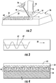
- Figure 2 illustrates one exemplary practice for application of an abrasion resistant surface covering 32 using a hardfacing treatment across a surface 34 of a work piece 36 such as a grouser bar 20, cutting edge 12, work tool 14 or any other metal structure as may be desired.
- a work piece 36 such as a grouser bar 20, cutting edge 12, work tool 14 or any other metal structure as may be desired.
- the surface 34 being treated may be positioned in generally opposing relation to a welding head 50 including an electrode 52 of consumable mild steel wire or the like.
- the electrode 52 is liquefied and forms a liquid pool 53 across the surface 34.
- a portion of the material forming the work piece 36 may also undergo melting to a relatively shallow depth, thereby providing additional liquid to the liquid pool 53.
- the liquid pool may be developed progressively by moving the welding head 50 relative to the surface of the work piece 36 as indicated by the directional arrow.
- the welding head 50 may remain stationary with relative movement of the work piece 36 if desired.
- the use of the welding head 50 with an electrode 52 of consumable character may be beneficial in many environments of use, it is contemplated that virtually any localized heating technique may be used to form the liquid pool 53 across the surface 34 being treated.
- the use the electrode 52 may be of a non-consumable character such that the liquid pool 53 is formed exclusively from the material making up the work piece 36.
- a torch or other heating device may be used in place of the welding head 50 either with or without a consumable member. Accordingly, the formation of the liquid pool 53 is in no way dependent upon the use of any particular equipment or process.
- Particles 56 of wear resistant material are delivered to the liquid pool 53 for development of a wear resistant composite alloy upon resolidification of the liquid pool 53 to form the abrasion resistant surface covering 32.
- one suitable material for the particles 56 is cemented tungsten carbide bonded together with cobalt.
- One potentially useful source of suitable particles 56 is cemented tungsten carbide of fractal dimensionality recovered from ground drill bits used in machining operations.
- other materials may likewise be utilized if desired.
- the particles 56 may be formed from other materials including, without limitation, cast tungsten carbide, macrocrystalline tungsten carbide as well as carbides of other metals including molybdenum, chromium, vanadium, titanium, tantalum, beryllium, columbium, and blends thereof characterized by enhanced wear resistance relative to the substrate material forming the work piece 36.
- the resultant abrasion resistant surface covering 32 includes the particles 56 of the wear-resistant material within a bonding matrix of steel or other base metal that previously formed the liquid pool 53.
- the liquid pool 53 is disposed at a relatively localized position and remains in a liquid state for a limited period of time before resolidification takes place.
- one exemplary particle delivery practice may utilize a drop tube 58 of substantially hollow construction which moves along a path generally behind the welding head 50.
- the particles 56 are typically applied at a level of about of about 0.1 to about 0.3 grams per square centimeter of the treatment zone, although higher or lower levels may be used if desired.
- the treatment zone width 60 provided by a pass of the welding head 50 and the drop tube 58 may be controlled by the pattern of movement of the welding head 50.
- the welding head 50 may move in a substantially straight line with the drop tube 58 following directly behind.
- Such a straight line pattern may typically be used to yield a treatment zone width 60 of about 15 millimeters or less.
- the welding head may be moved in a generally zigzag pattern 62 such as is shown by the solid line in Figure 4 with the drop tube 58 trailing in a substantially straight path 63 generally along the middle of the zigzag pattern 62 as shown by the dotted line in Figure 4 .
- the zigzag pattern 62 provides a wider liquid pool for acceptance of the particles 56 which may be deposited at the midpoint of the formed pool.
- the welding head 50 may make multiple passes in adjacent relation to one another to substantially cover any portion of the surface 34 as may be desired.
- packing factor refers to the ratio of the volume of the composite alloy occupied by the applied particles in the solidified state within a defined region relative to the volume of the abrasion resistant surface covering 32 within that defined region.
- packing factor refers to the ratio of the volume of the composite alloy occupied by the applied particles in the solidified state within a defined region relative to the volume of the abrasion resistant surface covering 32 within that defined region.
- one or more cross-sections may be cut through the abrasion resistant surface covering 32 and the underlying work piece 36 as shown diagrammatically in Figure 4 .
- the cross section includes a portion of the work piece 36 with the overlying abrasion resistant surface covering 32.
- the particles 56 are concentrated in a band extending away from the work piece 36.
- an outer zone 65 having very few particles may be disposed at the extreme outer surface.
- This outer zone 65 is formed substantially from the matrix material generated by the melting electrode 52.
- the outer zone 65 may tend to exhibit initial rapid wear until a concentrated zone of the particles 56 becomes exposed. Thereafter, wear is substantially reduced.
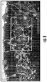
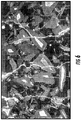
- Figures 5-8 present micrographs of applied abrasion resistant surface coverings showing representative orientations corresponding substantially to Figure 4 .
- the boxes in Figures 5 and 7 extend generally from the underlying work piece to the lower edge of the outer zone, thereby illustrating the concentration of particles in that region.
- the cross sections may be etched and polished to display the particles 56 within the matrix.
- a measurement zone 66 may then be defined within the etched and polished surface.
- the ratio of the surface area occupied by the particles 56 within the measurement zone 66 to the total area of the measurement zone 66 defines an area occupancy ratio which may be used as a measurement of the packing factor.
- evaluating the surface area occupied by the particles 56 in a standardized measurement zone extending from the surface of the work piece 36 to a position about 3 millimeters above the surface of the work piece 36 may be useful in evaluating the packing factor in portions of the abrasion resistant surface covering 32 near the work piece 36 having high concentrations of particles 56.
- a single sample may be used, enhanced accuracy may be achieved by evaluating multiple samples and averaging the area occupancy ratios in those samples.
- the particles 56 of wear resistant material may be characterized by an effective diameter in the range of about +14 -120 mesh. That is, the particles will be small enough to pass through a U.S. Standard 14 mesh screen (1410 microns) and will be blocked from passing through a U.S. Standard 120 mesh screen (125 microns). Within this broad range, it may be desirable for significant percentages of particles to occupy sub-ranges to provide a diverse population of particle sizes. Such a diverse particle size distribution permits smaller particles to cooperatively fill spaces between the larger particles to enhance the overall packing factor.
- Table I Effective Diameter (Mesh) Wt. % +14 - 22 40% - 70% +22 - 32 10% - 25% +32 - 60 10% - 25% +60 - 120 3% - 10%
- Utilization of such particle size distributions may yield final packing factors of about 0.6 to about 0.7. For some applications, it may be desirable for at least 3% and more desirably about 5% to about 10% to have an effective diameter of +80 mesh such that those particles pass through an 80 mesh screen.
- the particle size distribution may be adjusted to substantially reduce or eliminate particles in the +14 - 22 mesh range thereby shifting the distribution towards smaller effective diameters corresponding to higher mesh numbers.
- minor percentage of particles having an effective diameter greater than 14 mesh or smaller than 120 mesh may be applied if desired. However, it may be desirable for about 95% or more by weight of the particles to be within the +14 - 120 mesh range.
- the final solidified composite alloy may be raised about 4 millimeters relative to the plane of the surface 34 being treated and extend to a depth of about 2 millimeters below the plane of the surface 34 being treated due to melting of the base material. However, these levels may be increased or decreased as desired.
- Figures 5 and 6 are cross-sectional micrographs of an abrasion resistant surface covering of tungsten carbide particles within a steel matrix utilizing cemented tungsten carbide particles with a size range of +14 -120 mesh. Approximately 64% by weight of the applied particle mass was in the size range +14 - 22 mesh. Approximately 16% by weight of the applied particle mass was in the size range +22 - 33 mesh. Approximately 16% by weight of the applied particle mass was in the size range +33 - 60 mesh. Approximately 4% by weight of the applied particle mass was in the size range +60 - 120 mesh.
- the particles were applied in a hardfacing procedure at a drop rate of 250 grams per minute using a weld head with a wire speed of 350 inches per minute, a travel speed of 10.8 inches per minute and a voltage of 29 volts. Based on relative area occupancy, the packing factor of the tungsten carbide particles was in the range of 0.6 to 0.7.
- Figures 7 and 8 are cross-sectional micrographs of an abrasion resistant surface covering of tungsten carbide particles within a steel matrix utilizing cemented tungsten carbide particles with a size range of +14 -24 mesh.
- the test procedures as outlined in Example 1 were repeated in all respects except that the abrasion resistant material utilized cemented tungsten carbide particles with a size range of +14 -24 mesh. Based on relative area occupancy, the packing factor of the tungsten carbide particles was in the range of 0.4 to 0.5.
- a work piece including an abrasion resistant surface covering consistent with the present disclosure may find application in virtually any environment of use wherein metal articles are subjected to abrasive wear.
- Such environments may include mining, construction, farming, hydrocarbon extraction, transportation, or any other industry known in the art.
- such an abrasion resistant surface covering may be applied in bonded relation to surfaces of a cutting edge or work tool in a mobile or fixed machine.
- an abrasion resistant surface covering consistent with the present disclosure may be applied across one or more surfaces of a grouser bar on a track shoe for a track-type vehicle.
- Such track-type vehicles may include crawler-type bulldozers, rippers, pipelayers, loaders, excavators and the like.
- the track shoe defines a ground-engaging surface at the exterior of a track.
- the abrasion resistant surface covering provides enhanced abrasion resistance thereby prolonging useful life and enhanced machine productivity.
Landscapes
- Chemical & Material Sciences (AREA)
- Engineering & Computer Science (AREA)
- Materials Engineering (AREA)
- Organic Chemistry (AREA)
- Mechanical Engineering (AREA)
- Chemical Kinetics & Catalysis (AREA)
- Metallurgy (AREA)
- Physics & Mathematics (AREA)
- Plasma & Fusion (AREA)
- Wood Science & Technology (AREA)
- Life Sciences & Earth Sciences (AREA)
- Inorganic Chemistry (AREA)
- Powder Metallurgy (AREA)
- Other Surface Treatments For Metallic Materials (AREA)
- Coating By Spraying Or Casting (AREA)
- Manufacture Of Alloys Or Alloy Compounds (AREA)
- Earth Drilling (AREA)
Applications Claiming Priority (2)
| Application Number | Priority Date | Filing Date | Title |
|---|---|---|---|
| US11698608P | 2008-11-21 | 2008-11-21 | |
| PCT/US2009/057630 WO2010059287A2 (en) | 2008-11-21 | 2009-09-21 | Abrasion resistant composition |
Publications (3)
| Publication Number | Publication Date |
|---|---|
| EP2349626A2 EP2349626A2 (en) | 2011-08-03 |
| EP2349626A4 EP2349626A4 (en) | 2013-11-20 |
| EP2349626B1 true EP2349626B1 (en) | 2017-05-03 |
Family
ID=42198730
Family Applications (1)
| Application Number | Title | Priority Date | Filing Date |
|---|---|---|---|
| EP09827925.0A Active EP2349626B1 (en) | 2008-11-21 | 2009-09-21 | Abrasion resistant composition |
Country Status (10)
| Country | Link |
|---|---|
| US (1) | US8721761B2 (ja) |
| EP (1) | EP2349626B1 (ja) |
| JP (1) | JP5540005B2 (ja) |
| CN (1) | CN102223982B (ja) |
| AU (1) | AU2009318054B2 (ja) |
| CA (1) | CA2743137C (ja) |
| MX (1) | MX2011005342A (ja) |
| RU (1) | RU2011125305A (ja) |
| WO (1) | WO2010059287A2 (ja) |
| ZA (1) | ZA201103402B (ja) |
Families Citing this family (9)
| Publication number | Priority date | Publication date | Assignee | Title |
|---|---|---|---|---|
| US9283621B2 (en) | 2012-06-21 | 2016-03-15 | Deere & Company | Method for forming a composite article |
| EP2857140B1 (en) | 2013-10-02 | 2019-04-03 | Oerlikon Metco (US) Inc. | Brazing rod for forming a wear resistant coating and wear resistant coating |
| US9321117B2 (en) | 2014-03-18 | 2016-04-26 | Vermeer Manufacturing Company | Automatic system for abrasive hardfacing |
| US9528171B2 (en) | 2014-09-16 | 2016-12-27 | Caterpillar Inc. | Alloy for seal ring, seal ring, and method of making seal ring for seal assembly of machine |
| DE112014007184T5 (de) * | 2014-11-18 | 2017-08-24 | Komatsu Ltd. | Maschinenbauteil und Verfahren zum Herstellen desselben |
| JP6463648B2 (ja) * | 2015-03-03 | 2019-02-06 | アイエヌジ商事株式会社 | 肉盛り方法 |
| US9775296B2 (en) * | 2015-06-04 | 2017-10-03 | Cnh Industrial America Llc | Agricultural concave having a component coated with a high hardness material |
| US10040096B2 (en) | 2015-07-17 | 2018-08-07 | Caterpillar Inc. | Abrasion resistant material tandem welding |
| CN106513929B (zh) * | 2016-09-26 | 2019-06-25 | 湖北汽车工业学院 | 铝合金表面B4C颗粒增强Al基复合熔覆层及制备方法 |
Family Cites Families (51)
| Publication number | Priority date | Publication date | Assignee | Title |
|---|---|---|---|---|
| US2105079A (en) | 1936-10-29 | 1938-01-11 | Electric Arc Cutting & Welding | Arc welding system |
| US2549930A (en) | 1949-09-19 | 1951-04-24 | Caterpillar Tractor Co | Selective tempering by induction means |
| US2874005A (en) | 1954-10-01 | 1959-02-17 | Bofors Ab | Reinforcement means for a track plate of a track laying vehicle |
| US2849259A (en) | 1954-10-01 | 1958-08-26 | Bofors Ab | Track plate for a track of a track-laying vehicle |
| US3060307A (en) | 1960-09-21 | 1962-10-23 | R I Patents Inc | Apparatus and method for producing alloy welds |
| US3172991A (en) | 1962-07-30 | 1965-03-09 | Roman F Arnoldy | Feeder for welds |
| US3286379A (en) | 1964-01-13 | 1966-11-22 | Petersen Gerald A | Digging tooth with corrugated cross-section |
| US3405247A (en) | 1964-12-03 | 1968-10-08 | Armco Steel Corp | Method and apparatus for producing smooth overlays for tool joints |
| US3790353A (en) | 1972-02-22 | 1974-02-05 | Servco Co Division Smith Int I | Hard-facing article |
| US3912338A (en) | 1974-02-21 | 1975-10-14 | Kennametal Inc | Wear resistant grouser bar |
| US3936655A (en) | 1974-09-26 | 1976-02-03 | Arnoldy Roman F | Magnetic feeding of powder in submerged arc welding |
| US3972570A (en) | 1975-04-17 | 1976-08-03 | Caterpillar Tractor Co. | Wear-resistant composite track shoe |
| US4097711A (en) | 1976-09-16 | 1978-06-27 | Ingersoll-Rand Company | Roller shell hard coating |
| US4243727A (en) | 1977-04-25 | 1981-01-06 | Hughes Tool Company | Surface smoothed tool joint hardfacing |
| US4434642A (en) | 1981-06-01 | 1984-03-06 | Industrial Parts Depot | Reverse forging or replacement grouser bars |
| US4404450A (en) | 1982-01-11 | 1983-09-13 | Weldon John F | Roll welding machine and method of reconditioning caster rolls |
| US4613741A (en) | 1984-10-03 | 1986-09-23 | Arnoldy Roman F | Feeder for welds |
| US4723060A (en) | 1985-07-05 | 1988-02-02 | Arnoldy Roman F | Feeder equalizer and homogenizer |
| JPH0649228B2 (ja) * | 1986-03-25 | 1994-06-29 | 大同特殊鋼株式会社 | 工具の製造方法 |
| JPH026097A (ja) * | 1988-06-25 | 1990-01-10 | Kubota Ltd | 耐摩耗肉盛層 |
| US5147996A (en) | 1989-09-15 | 1992-09-15 | Grant Tfw, Inc. | Tool joint |
| US5010225A (en) | 1989-09-15 | 1991-04-23 | Grant Tfw | Tool joint and method of hardfacing same |
| US5111600A (en) | 1991-07-30 | 1992-05-12 | Caterpillar Inc. | Tooth with hard material applied to selected surfaces |
| US5516053A (en) | 1993-10-07 | 1996-05-14 | Hannu; Donald W. | Welded metal hardfacing pattern for cone crusher surfaces |
| US5663512A (en) * | 1994-11-21 | 1997-09-02 | Baker Hughes Inc. | Hardfacing composition for earth-boring bits |
| JP3014307B2 (ja) * | 1995-10-16 | 2000-02-28 | 株式会社栗本鐵工所 | 内張りライナー |
| CA2199780C (en) * | 1996-03-12 | 2005-08-30 | Dah-Ben Liang | Rock bit with hardfacing material incorporating spherical cast carbide particles |
| CN1053134C (zh) * | 1996-03-27 | 2000-06-07 | 煤炭科学研究总院北京建井研究所 | 耐磨堆焊管状焊丝 |
| US6138779A (en) | 1998-01-16 | 2000-10-31 | Dresser Industries, Inc. | Hardfacing having coated ceramic particles or coated particles of other hard materials placed on a rotary cone cutter |
| US6017103A (en) | 1998-06-30 | 2000-01-25 | Caterpillar Inc. | Track shoe |
| JP2000141037A (ja) * | 1998-11-12 | 2000-05-23 | Hirose Kogyo Kk | 肉盛り溶接の溶接方法 |
| KR20000046435A (ko) | 1998-12-31 | 2000-07-25 | 추호석 | 크롤러용 고강도 내마모 트랙 슈 |
| JP3479668B2 (ja) | 1999-03-23 | 2003-12-15 | 株式会社小松製作所 | 装軌車両の足回り装置およびその肉盛強化方法 |
| JP2001047235A (ja) * | 1999-08-04 | 2001-02-20 | Toshiba Mach Co Ltd | プラスチック成形機用の中空部材及びその製造方法 |
| US6571493B2 (en) | 1999-12-27 | 2003-06-03 | Komatsu Ltd. | Cutting edge |
| US6360832B1 (en) * | 2000-01-03 | 2002-03-26 | Baker Hughes Incorporated | Hardfacing with multiple grade layers |
| US6564884B2 (en) | 2000-07-25 | 2003-05-20 | Halliburton Energy Services, Inc. | Wear protection on a rock bit |
| US6651756B1 (en) | 2000-11-17 | 2003-11-25 | Baker Hughes Incorporated | Steel body drill bits with tailored hardfacing structural elements |
| US6649858B2 (en) | 2001-07-17 | 2003-11-18 | Illinois Tool Works Inc. | Multi-application welding system and method |
| US6659206B2 (en) * | 2001-10-29 | 2003-12-09 | Smith International, Inc. | Hardfacing composition for rock bits |
| CN1244431C (zh) * | 2002-11-04 | 2006-03-08 | 江汉石油钻头股份有限公司 | 一种管状碳化钨焊条 |
| US20040157066A1 (en) | 2003-02-07 | 2004-08-12 | Arzoumanidis G. Alexis | Method of applying a hardcoating typically provided on downhole tools, and a system and apparatus having such a hardcoating |
| US7163754B2 (en) | 2003-10-23 | 2007-01-16 | Deere & Company | Sprocket wheel having a metallurgically bonded coating and method for producing same |
| JP2005305449A (ja) * | 2004-04-16 | 2005-11-04 | Sumitomo Metal Ind Ltd | 熱間加工用工具 |
| US7666244B2 (en) * | 2004-07-08 | 2010-02-23 | Smith International, Inc. | Hardfacing milled-tooth drill bits using super dense carbide pellets |
| US7240746B2 (en) * | 2004-09-23 | 2007-07-10 | Baker Hughes Incorporated | Bit gage hardfacing |
| US7621347B2 (en) * | 2005-03-17 | 2009-11-24 | Baker Hughes Incorporated | Bit leg and cone hardfacing for earth-boring bit |
| KR200396650Y1 (ko) | 2005-07-12 | 2005-09-23 | 윤경식 | 스크류 로터 블레이드 |
| KR20080063384A (ko) * | 2005-10-03 | 2008-07-03 | 케나메탈 아이엔씨. | 표면경화용 조성물 및 표면경화용 퇴적물을 구비한 물품 |
| JP4860320B2 (ja) * | 2006-03-30 | 2012-01-25 | 株式会社小松製作所 | 耐摩耗粒子及び耐摩耗構造部材 |
| WO2007114524A1 (ja) | 2006-03-30 | 2007-10-11 | Komatsu Ltd. | 耐摩耗粒子及び耐摩耗構造部材 |
-
2009
- 2009-09-21 WO PCT/US2009/057630 patent/WO2010059287A2/en active Application Filing
- 2009-09-21 EP EP09827925.0A patent/EP2349626B1/en active Active
- 2009-09-21 RU RU2011125305/02A patent/RU2011125305A/ru not_active Application Discontinuation
- 2009-09-21 JP JP2011537447A patent/JP5540005B2/ja active Active
- 2009-09-21 AU AU2009318054A patent/AU2009318054B2/en active Active
- 2009-09-21 CN CN200980146544.6A patent/CN102223982B/zh active Active
- 2009-09-21 CA CA2743137A patent/CA2743137C/en active Active
- 2009-09-21 MX MX2011005342A patent/MX2011005342A/es not_active Application Discontinuation
- 2009-11-11 US US12/616,315 patent/US8721761B2/en not_active Expired - Fee Related
-
2011
- 2011-05-10 ZA ZA2011/03402A patent/ZA201103402B/en unknown
Also Published As
| Publication number | Publication date |
|---|---|
| JP2012509409A (ja) | 2012-04-19 |
| WO2010059287A3 (en) | 2010-07-15 |
| MX2011005342A (es) | 2011-08-12 |
| RU2011125305A (ru) | 2012-12-27 |
| CN102223982A (zh) | 2011-10-19 |
| EP2349626A2 (en) | 2011-08-03 |
| CN102223982B (zh) | 2015-04-15 |
| ZA201103402B (en) | 2012-09-26 |
| CA2743137A1 (en) | 2010-05-27 |
| JP5540005B2 (ja) | 2014-07-02 |
| US20100215849A1 (en) | 2010-08-26 |
| AU2009318054B2 (en) | 2015-03-26 |
| US8721761B2 (en) | 2014-05-13 |
| AU2009318054A1 (en) | 2010-05-27 |
| EP2349626A4 (en) | 2013-11-20 |
| CA2743137C (en) | 2016-07-12 |
| WO2010059287A2 (en) | 2010-05-27 |
Similar Documents
| Publication | Publication Date | Title |
|---|---|---|
| AU2009318053B2 (en) | Abrasion resistant track shoe grouser | |
| EP2349626B1 (en) | Abrasion resistant composition | |
| CN1195387A (zh) | 利用被包复的钻石颗粒进行表面硬化 | |
| US10835958B2 (en) | Wear-resistant component and method for producing the same | |
| US20170014901A1 (en) | Wear Part with Hardfacing and Method of Making Same | |
| KR101634023B1 (ko) | 굴착 클로 및 굴착 클로용 보디 | |
| JP2007069227A (ja) | 肉盛用溶接材及びこれを用いて硬装した掘削工具並びに摩耗防止用プレート | |
| AU2017338154B2 (en) | Part resistant to erosion wear and manufacturing method for same | |
| CN108356439A (zh) | 一种高硬度高耐磨抗冲击钻杆修复药芯焊丝 | |
| AU2021200646C1 (en) | Grader blade | |
| Fischer et al. | Abrasion resistant track shoe grouser | |
| JP4439238B2 (ja) | 掘削用切刃 | |
| US10040096B2 (en) | Abrasion resistant material tandem welding | |
| Farmer | How to Select a Hardfacing Alloy | |
| GB2517958A (en) | Self-sharpening tooth |
Legal Events
| Date | Code | Title | Description |
|---|---|---|---|
| PUAI | Public reference made under article 153(3) epc to a published international application that has entered the european phase |
Free format text: ORIGINAL CODE: 0009012 |
|
| 17P | Request for examination filed |
Effective date: 20110506 |
|
| AK | Designated contracting states |
Kind code of ref document: A2 Designated state(s): AT BE BG CH CY CZ DE DK EE ES FI FR GB GR HR HU IE IS IT LI LT LU LV MC MK MT NL NO PL PT RO SE SI SK SM TR |
|
| DAX | Request for extension of the european patent (deleted) | ||
| A4 | Supplementary search report drawn up and despatched |
Effective date: 20131021 |
|
| RIC1 | Information provided on ipc code assigned before grant |
Ipc: B23K 9/04 20060101ALI20131015BHEP Ipc: B23K 9/00 20060101AFI20131015BHEP |
|
| REG | Reference to a national code |
Ref country code: DE Ref legal event code: R079 Ref document number: 602009045922 Country of ref document: DE Free format text: PREVIOUS MAIN CLASS: B23K0009000000 Ipc: C09D0001000000 |
|
| GRAJ | Information related to disapproval of communication of intention to grant by the applicant or resumption of examination proceedings by the epo deleted |
Free format text: ORIGINAL CODE: EPIDOSDIGR1 |
|
| GRAP | Despatch of communication of intention to grant a patent |
Free format text: ORIGINAL CODE: EPIDOSNIGR1 |
|
| RIC1 | Information provided on ipc code assigned before grant |
Ipc: C09D 7/12 20060101ALI20161103BHEP Ipc: C09D 1/00 20060101AFI20161103BHEP Ipc: C23C 4/06 20060101ALI20161103BHEP Ipc: C23C 4/04 20060101ALI20161103BHEP Ipc: B23K 9/04 20060101ALI20161103BHEP Ipc: C08K 3/14 20060101ALI20161103BHEP Ipc: C23C 24/10 20060101ALI20161103BHEP |
|
| INTG | Intention to grant announced |
Effective date: 20161129 |
|
| RIN1 | Information on inventor provided before grant (corrected) |
Inventor name: FISCHER, KEITH D. Inventor name: HENDERSON, STEPHEN L. Inventor name: BARNES, CHRISTOPHER |
|
| GRAS | Grant fee paid |
Free format text: ORIGINAL CODE: EPIDOSNIGR3 |
|
| GRAA | (expected) grant |
Free format text: ORIGINAL CODE: 0009210 |
|
| AK | Designated contracting states |
Kind code of ref document: B1 Designated state(s): AT BE BG CH CY CZ DE DK EE ES FI FR GB GR HR HU IE IS IT LI LT LU LV MC MK MT NL NO PL PT RO SE SI SK SM TR |
|
| REG | Reference to a national code |
Ref country code: GB Ref legal event code: FG4D |
|
| REG | Reference to a national code |
Ref country code: AT Ref legal event code: REF Ref document number: 889955 Country of ref document: AT Kind code of ref document: T Effective date: 20170515 Ref country code: CH Ref legal event code: EP |
|
| REG | Reference to a national code |
Ref country code: IE Ref legal event code: FG4D |
|
| REG | Reference to a national code |
Ref country code: DE Ref legal event code: R096 Ref document number: 602009045922 Country of ref document: DE |
|
| REG | Reference to a national code |
Ref country code: NL Ref legal event code: MP Effective date: 20170503 |
|
| REG | Reference to a national code |
Ref country code: AT Ref legal event code: MK05 Ref document number: 889955 Country of ref document: AT Kind code of ref document: T Effective date: 20170503 |
|
| REG | Reference to a national code |
Ref country code: LT Ref legal event code: MG4D |
|
| PG25 | Lapsed in a contracting state [announced via postgrant information from national office to epo] |
Ref country code: LT Free format text: LAPSE BECAUSE OF FAILURE TO SUBMIT A TRANSLATION OF THE DESCRIPTION OR TO PAY THE FEE WITHIN THE PRESCRIBED TIME-LIMIT Effective date: 20170503 Ref country code: FI Free format text: LAPSE BECAUSE OF FAILURE TO SUBMIT A TRANSLATION OF THE DESCRIPTION OR TO PAY THE FEE WITHIN THE PRESCRIBED TIME-LIMIT Effective date: 20170503 Ref country code: GR Free format text: LAPSE BECAUSE OF FAILURE TO SUBMIT A TRANSLATION OF THE DESCRIPTION OR TO PAY THE FEE WITHIN THE PRESCRIBED TIME-LIMIT Effective date: 20170804 Ref country code: AT Free format text: LAPSE BECAUSE OF FAILURE TO SUBMIT A TRANSLATION OF THE DESCRIPTION OR TO PAY THE FEE WITHIN THE PRESCRIBED TIME-LIMIT Effective date: 20170503 Ref country code: ES Free format text: LAPSE BECAUSE OF FAILURE TO SUBMIT A TRANSLATION OF THE DESCRIPTION OR TO PAY THE FEE WITHIN THE PRESCRIBED TIME-LIMIT Effective date: 20170503 Ref country code: HR Free format text: LAPSE BECAUSE OF FAILURE TO SUBMIT A TRANSLATION OF THE DESCRIPTION OR TO PAY THE FEE WITHIN THE PRESCRIBED TIME-LIMIT Effective date: 20170503 Ref country code: NO Free format text: LAPSE BECAUSE OF FAILURE TO SUBMIT A TRANSLATION OF THE DESCRIPTION OR TO PAY THE FEE WITHIN THE PRESCRIBED TIME-LIMIT Effective date: 20170803 |
|
| PG25 | Lapsed in a contracting state [announced via postgrant information from national office to epo] |
Ref country code: LV Free format text: LAPSE BECAUSE OF FAILURE TO SUBMIT A TRANSLATION OF THE DESCRIPTION OR TO PAY THE FEE WITHIN THE PRESCRIBED TIME-LIMIT Effective date: 20170503 Ref country code: NL Free format text: LAPSE BECAUSE OF FAILURE TO SUBMIT A TRANSLATION OF THE DESCRIPTION OR TO PAY THE FEE WITHIN THE PRESCRIBED TIME-LIMIT Effective date: 20170503 Ref country code: SE Free format text: LAPSE BECAUSE OF FAILURE TO SUBMIT A TRANSLATION OF THE DESCRIPTION OR TO PAY THE FEE WITHIN THE PRESCRIBED TIME-LIMIT Effective date: 20170503 Ref country code: BG Free format text: LAPSE BECAUSE OF FAILURE TO SUBMIT A TRANSLATION OF THE DESCRIPTION OR TO PAY THE FEE WITHIN THE PRESCRIBED TIME-LIMIT Effective date: 20170803 Ref country code: IS Free format text: LAPSE BECAUSE OF FAILURE TO SUBMIT A TRANSLATION OF THE DESCRIPTION OR TO PAY THE FEE WITHIN THE PRESCRIBED TIME-LIMIT Effective date: 20170903 Ref country code: PL Free format text: LAPSE BECAUSE OF FAILURE TO SUBMIT A TRANSLATION OF THE DESCRIPTION OR TO PAY THE FEE WITHIN THE PRESCRIBED TIME-LIMIT Effective date: 20170503 |
|
| PG25 | Lapsed in a contracting state [announced via postgrant information from national office to epo] |
Ref country code: DK Free format text: LAPSE BECAUSE OF FAILURE TO SUBMIT A TRANSLATION OF THE DESCRIPTION OR TO PAY THE FEE WITHIN THE PRESCRIBED TIME-LIMIT Effective date: 20170503 Ref country code: EE Free format text: LAPSE BECAUSE OF FAILURE TO SUBMIT A TRANSLATION OF THE DESCRIPTION OR TO PAY THE FEE WITHIN THE PRESCRIBED TIME-LIMIT Effective date: 20170503 Ref country code: SK Free format text: LAPSE BECAUSE OF FAILURE TO SUBMIT A TRANSLATION OF THE DESCRIPTION OR TO PAY THE FEE WITHIN THE PRESCRIBED TIME-LIMIT Effective date: 20170503 Ref country code: CZ Free format text: LAPSE BECAUSE OF FAILURE TO SUBMIT A TRANSLATION OF THE DESCRIPTION OR TO PAY THE FEE WITHIN THE PRESCRIBED TIME-LIMIT Effective date: 20170503 Ref country code: RO Free format text: LAPSE BECAUSE OF FAILURE TO SUBMIT A TRANSLATION OF THE DESCRIPTION OR TO PAY THE FEE WITHIN THE PRESCRIBED TIME-LIMIT Effective date: 20170503 |
|
| REG | Reference to a national code |
Ref country code: DE Ref legal event code: R097 Ref document number: 602009045922 Country of ref document: DE |
|
| PG25 | Lapsed in a contracting state [announced via postgrant information from national office to epo] |
Ref country code: SM Free format text: LAPSE BECAUSE OF FAILURE TO SUBMIT A TRANSLATION OF THE DESCRIPTION OR TO PAY THE FEE WITHIN THE PRESCRIBED TIME-LIMIT Effective date: 20170503 |
|
| PLBE | No opposition filed within time limit |
Free format text: ORIGINAL CODE: 0009261 |
|
| STAA | Information on the status of an ep patent application or granted ep patent |
Free format text: STATUS: NO OPPOSITION FILED WITHIN TIME LIMIT |
|
| 26N | No opposition filed |
Effective date: 20180206 |
|
| REG | Reference to a national code |
Ref country code: CH Ref legal event code: PL |
|
| GBPC | Gb: european patent ceased through non-payment of renewal fee |
Effective date: 20170921 |
|
| PG25 | Lapsed in a contracting state [announced via postgrant information from national office to epo] |
Ref country code: MC Free format text: LAPSE BECAUSE OF FAILURE TO SUBMIT A TRANSLATION OF THE DESCRIPTION OR TO PAY THE FEE WITHIN THE PRESCRIBED TIME-LIMIT Effective date: 20170503 Ref country code: SI Free format text: LAPSE BECAUSE OF FAILURE TO SUBMIT A TRANSLATION OF THE DESCRIPTION OR TO PAY THE FEE WITHIN THE PRESCRIBED TIME-LIMIT Effective date: 20170503 |
|
| REG | Reference to a national code |
Ref country code: IE Ref legal event code: MM4A |
|
| REG | Reference to a national code |
Ref country code: BE Ref legal event code: MM Effective date: 20170930 |
|
| PG25 | Lapsed in a contracting state [announced via postgrant information from national office to epo] |
Ref country code: LU Free format text: LAPSE BECAUSE OF NON-PAYMENT OF DUE FEES Effective date: 20170921 |
|
| REG | Reference to a national code |
Ref country code: FR Ref legal event code: ST Effective date: 20180531 |
|
| PG25 | Lapsed in a contracting state [announced via postgrant information from national office to epo] |
Ref country code: GB Free format text: LAPSE BECAUSE OF NON-PAYMENT OF DUE FEES Effective date: 20170921 Ref country code: LI Free format text: LAPSE BECAUSE OF NON-PAYMENT OF DUE FEES Effective date: 20170930 Ref country code: CH Free format text: LAPSE BECAUSE OF NON-PAYMENT OF DUE FEES Effective date: 20170930 Ref country code: IE Free format text: LAPSE BECAUSE OF NON-PAYMENT OF DUE FEES Effective date: 20170921 |
|
| PG25 | Lapsed in a contracting state [announced via postgrant information from national office to epo] |
Ref country code: BE Free format text: LAPSE BECAUSE OF NON-PAYMENT OF DUE FEES Effective date: 20170930 Ref country code: FR Free format text: LAPSE BECAUSE OF NON-PAYMENT OF DUE FEES Effective date: 20171002 |
|
| PG25 | Lapsed in a contracting state [announced via postgrant information from national office to epo] |
Ref country code: MT Free format text: LAPSE BECAUSE OF NON-PAYMENT OF DUE FEES Effective date: 20170921 |
|
| PG25 | Lapsed in a contracting state [announced via postgrant information from national office to epo] |
Ref country code: HU Free format text: LAPSE BECAUSE OF FAILURE TO SUBMIT A TRANSLATION OF THE DESCRIPTION OR TO PAY THE FEE WITHIN THE PRESCRIBED TIME-LIMIT; INVALID AB INITIO Effective date: 20090921 |
|
| PG25 | Lapsed in a contracting state [announced via postgrant information from national office to epo] |
Ref country code: CY Free format text: LAPSE BECAUSE OF NON-PAYMENT OF DUE FEES Effective date: 20170503 |
|
| PG25 | Lapsed in a contracting state [announced via postgrant information from national office to epo] |
Ref country code: MK Free format text: LAPSE BECAUSE OF FAILURE TO SUBMIT A TRANSLATION OF THE DESCRIPTION OR TO PAY THE FEE WITHIN THE PRESCRIBED TIME-LIMIT Effective date: 20170503 |
|
| PG25 | Lapsed in a contracting state [announced via postgrant information from national office to epo] |
Ref country code: TR Free format text: LAPSE BECAUSE OF FAILURE TO SUBMIT A TRANSLATION OF THE DESCRIPTION OR TO PAY THE FEE WITHIN THE PRESCRIBED TIME-LIMIT Effective date: 20170503 |
|
| PG25 | Lapsed in a contracting state [announced via postgrant information from national office to epo] |
Ref country code: PT Free format text: LAPSE BECAUSE OF FAILURE TO SUBMIT A TRANSLATION OF THE DESCRIPTION OR TO PAY THE FEE WITHIN THE PRESCRIBED TIME-LIMIT Effective date: 20170503 |
|
| P01 | Opt-out of the competence of the unified patent court (upc) registered |
Effective date: 20230517 |
|
| PGFP | Annual fee paid to national office [announced via postgrant information from national office to epo] |
Ref country code: IT Payment date: 20230822 Year of fee payment: 15 |
|
| PGFP | Annual fee paid to national office [announced via postgrant information from national office to epo] |
Ref country code: DE Payment date: 20230822 Year of fee payment: 15 |