EP2349110B1 - Modulare gelenkprothese - Google Patents
Modulare gelenkprothese Download PDFInfo
- Publication number
- EP2349110B1 EP2349110B1 EP09737333.6A EP09737333A EP2349110B1 EP 2349110 B1 EP2349110 B1 EP 2349110B1 EP 09737333 A EP09737333 A EP 09737333A EP 2349110 B1 EP2349110 B1 EP 2349110B1
- Authority
- EP
- European Patent Office
- Prior art keywords
- module
- neck
- stem
- joint prosthesis
- prosthesis according
- Prior art date
- Legal status (The legal status is an assumption and is not a legal conclusion. Google has not performed a legal analysis and makes no representation as to the accuracy of the status listed.)
- Not-in-force
Links
- 238000003780 insertion Methods 0.000 claims description 18
- 230000037431 insertion Effects 0.000 claims description 18
- 210000000988 bone and bone Anatomy 0.000 claims description 9
- 238000006073 displacement reaction Methods 0.000 claims description 7
- 210000001185 bone marrow Anatomy 0.000 claims description 5
- 239000011343 solid material Substances 0.000 claims description 4
- 229910045601 alloy Inorganic materials 0.000 claims description 2
- 239000000956 alloy Substances 0.000 claims description 2
- 238000010276 construction Methods 0.000 claims description 2
- 229910001069 Ti alloy Inorganic materials 0.000 claims 1
- 230000001737 promoting effect Effects 0.000 claims 1
- 210000000689 upper leg Anatomy 0.000 description 5
- 238000002271 resection Methods 0.000 description 3
- 210000001519 tissue Anatomy 0.000 description 3
- 206010027476 Metastases Diseases 0.000 description 2
- 230000005540 biological transmission Effects 0.000 description 2
- 239000007943 implant Substances 0.000 description 2
- 208000015181 infectious disease Diseases 0.000 description 2
- 208000014674 injury Diseases 0.000 description 2
- 239000007769 metal material Substances 0.000 description 2
- 230000008733 trauma Effects 0.000 description 2
- 206010061307 Neck deformity Diseases 0.000 description 1
- RTAQQCXQSZGOHL-UHFFFAOYSA-N Titanium Chemical compound [Ti] RTAQQCXQSZGOHL-UHFFFAOYSA-N 0.000 description 1
- 230000006978 adaptation Effects 0.000 description 1
- 210000003484 anatomy Anatomy 0.000 description 1
- 230000015572 biosynthetic process Effects 0.000 description 1
- 239000003795 chemical substances by application Substances 0.000 description 1
- 230000006835 compression Effects 0.000 description 1
- 238000007906 compression Methods 0.000 description 1
- 230000001419 dependent effect Effects 0.000 description 1
- 230000002349 favourable effect Effects 0.000 description 1
- 210000000501 femur body Anatomy 0.000 description 1
- 238000005755 formation reaction Methods 0.000 description 1
- 210000003205 muscle Anatomy 0.000 description 1
- 229910052758 niobium Inorganic materials 0.000 description 1
- 239000010955 niobium Substances 0.000 description 1
- GUCVJGMIXFAOAE-UHFFFAOYSA-N niobium atom Chemical compound [Nb] GUCVJGMIXFAOAE-UHFFFAOYSA-N 0.000 description 1
- 230000000399 orthopedic effect Effects 0.000 description 1
- 238000001356 surgical procedure Methods 0.000 description 1
- 229910052715 tantalum Inorganic materials 0.000 description 1
- GUVRBAGPIYLISA-UHFFFAOYSA-N tantalum atom Chemical compound [Ta] GUVRBAGPIYLISA-UHFFFAOYSA-N 0.000 description 1
- 210000002435 tendon Anatomy 0.000 description 1
- 239000010936 titanium Substances 0.000 description 1
- 229910052719 titanium Inorganic materials 0.000 description 1
Images


Classifications
-
- A—HUMAN NECESSITIES
- A61—MEDICAL OR VETERINARY SCIENCE; HYGIENE
- A61F—FILTERS IMPLANTABLE INTO BLOOD VESSELS; PROSTHESES; DEVICES PROVIDING PATENCY TO, OR PREVENTING COLLAPSING OF, TUBULAR STRUCTURES OF THE BODY, e.g. STENTS; ORTHOPAEDIC, NURSING OR CONTRACEPTIVE DEVICES; FOMENTATION; TREATMENT OR PROTECTION OF EYES OR EARS; BANDAGES, DRESSINGS OR ABSORBENT PADS; FIRST-AID KITS
- A61F2/00—Filters implantable into blood vessels; Prostheses, i.e. artificial substitutes or replacements for parts of the body; Appliances for connecting them with the body; Devices providing patency to, or preventing collapsing of, tubular structures of the body, e.g. stents
- A61F2/02—Prostheses implantable into the body
- A61F2/30—Joints
-
- A—HUMAN NECESSITIES
- A61—MEDICAL OR VETERINARY SCIENCE; HYGIENE
- A61F—FILTERS IMPLANTABLE INTO BLOOD VESSELS; PROSTHESES; DEVICES PROVIDING PATENCY TO, OR PREVENTING COLLAPSING OF, TUBULAR STRUCTURES OF THE BODY, e.g. STENTS; ORTHOPAEDIC, NURSING OR CONTRACEPTIVE DEVICES; FOMENTATION; TREATMENT OR PROTECTION OF EYES OR EARS; BANDAGES, DRESSINGS OR ABSORBENT PADS; FIRST-AID KITS
- A61F2/00—Filters implantable into blood vessels; Prostheses, i.e. artificial substitutes or replacements for parts of the body; Appliances for connecting them with the body; Devices providing patency to, or preventing collapsing of, tubular structures of the body, e.g. stents
- A61F2/02—Prostheses implantable into the body
- A61F2/30—Joints
- A61F2/32—Joints for the hip
- A61F2/36—Femoral heads ; Femoral endoprostheses
-
- A—HUMAN NECESSITIES
- A61—MEDICAL OR VETERINARY SCIENCE; HYGIENE
- A61F—FILTERS IMPLANTABLE INTO BLOOD VESSELS; PROSTHESES; DEVICES PROVIDING PATENCY TO, OR PREVENTING COLLAPSING OF, TUBULAR STRUCTURES OF THE BODY, e.g. STENTS; ORTHOPAEDIC, NURSING OR CONTRACEPTIVE DEVICES; FOMENTATION; TREATMENT OR PROTECTION OF EYES OR EARS; BANDAGES, DRESSINGS OR ABSORBENT PADS; FIRST-AID KITS
- A61F2/00—Filters implantable into blood vessels; Prostheses, i.e. artificial substitutes or replacements for parts of the body; Appliances for connecting them with the body; Devices providing patency to, or preventing collapsing of, tubular structures of the body, e.g. stents
- A61F2/02—Prostheses implantable into the body
- A61F2/30—Joints
- A61F2002/30001—Additional features of subject-matter classified in A61F2/28, A61F2/30 and subgroups thereof
- A61F2002/30316—The prosthesis having different structural features at different locations within the same prosthesis; Connections between prosthetic parts; Special structural features of bone or joint prostheses not otherwise provided for
- A61F2002/30329—Connections or couplings between prosthetic parts, e.g. between modular parts; Connecting elements
- A61F2002/30331—Connections or couplings between prosthetic parts, e.g. between modular parts; Connecting elements made by longitudinally pushing a protrusion into a complementarily-shaped recess, e.g. held by friction fit
-
- A—HUMAN NECESSITIES
- A61—MEDICAL OR VETERINARY SCIENCE; HYGIENE
- A61F—FILTERS IMPLANTABLE INTO BLOOD VESSELS; PROSTHESES; DEVICES PROVIDING PATENCY TO, OR PREVENTING COLLAPSING OF, TUBULAR STRUCTURES OF THE BODY, e.g. STENTS; ORTHOPAEDIC, NURSING OR CONTRACEPTIVE DEVICES; FOMENTATION; TREATMENT OR PROTECTION OF EYES OR EARS; BANDAGES, DRESSINGS OR ABSORBENT PADS; FIRST-AID KITS
- A61F2/00—Filters implantable into blood vessels; Prostheses, i.e. artificial substitutes or replacements for parts of the body; Appliances for connecting them with the body; Devices providing patency to, or preventing collapsing of, tubular structures of the body, e.g. stents
- A61F2/02—Prostheses implantable into the body
- A61F2/30—Joints
- A61F2002/30001—Additional features of subject-matter classified in A61F2/28, A61F2/30 and subgroups thereof
- A61F2002/30316—The prosthesis having different structural features at different locations within the same prosthesis; Connections between prosthetic parts; Special structural features of bone or joint prostheses not otherwise provided for
- A61F2002/30329—Connections or couplings between prosthetic parts, e.g. between modular parts; Connecting elements
- A61F2002/30476—Connections or couplings between prosthetic parts, e.g. between modular parts; Connecting elements locked by an additional locking mechanism
- A61F2002/30495—Connections or couplings between prosthetic parts, e.g. between modular parts; Connecting elements locked by an additional locking mechanism using a locking ring
-
- A—HUMAN NECESSITIES
- A61—MEDICAL OR VETERINARY SCIENCE; HYGIENE
- A61F—FILTERS IMPLANTABLE INTO BLOOD VESSELS; PROSTHESES; DEVICES PROVIDING PATENCY TO, OR PREVENTING COLLAPSING OF, TUBULAR STRUCTURES OF THE BODY, e.g. STENTS; ORTHOPAEDIC, NURSING OR CONTRACEPTIVE DEVICES; FOMENTATION; TREATMENT OR PROTECTION OF EYES OR EARS; BANDAGES, DRESSINGS OR ABSORBENT PADS; FIRST-AID KITS
- A61F2/00—Filters implantable into blood vessels; Prostheses, i.e. artificial substitutes or replacements for parts of the body; Appliances for connecting them with the body; Devices providing patency to, or preventing collapsing of, tubular structures of the body, e.g. stents
- A61F2/02—Prostheses implantable into the body
- A61F2/30—Joints
- A61F2002/30001—Additional features of subject-matter classified in A61F2/28, A61F2/30 and subgroups thereof
- A61F2002/30316—The prosthesis having different structural features at different locations within the same prosthesis; Connections between prosthetic parts; Special structural features of bone or joint prostheses not otherwise provided for
- A61F2002/30535—Special structural features of bone or joint prostheses not otherwise provided for
- A61F2002/30604—Special structural features of bone or joint prostheses not otherwise provided for modular
-
- A—HUMAN NECESSITIES
- A61—MEDICAL OR VETERINARY SCIENCE; HYGIENE
- A61F—FILTERS IMPLANTABLE INTO BLOOD VESSELS; PROSTHESES; DEVICES PROVIDING PATENCY TO, OR PREVENTING COLLAPSING OF, TUBULAR STRUCTURES OF THE BODY, e.g. STENTS; ORTHOPAEDIC, NURSING OR CONTRACEPTIVE DEVICES; FOMENTATION; TREATMENT OR PROTECTION OF EYES OR EARS; BANDAGES, DRESSINGS OR ABSORBENT PADS; FIRST-AID KITS
- A61F2/00—Filters implantable into blood vessels; Prostheses, i.e. artificial substitutes or replacements for parts of the body; Appliances for connecting them with the body; Devices providing patency to, or preventing collapsing of, tubular structures of the body, e.g. stents
- A61F2/02—Prostheses implantable into the body
- A61F2/30—Joints
- A61F2002/30001—Additional features of subject-matter classified in A61F2/28, A61F2/30 and subgroups thereof
- A61F2002/30316—The prosthesis having different structural features at different locations within the same prosthesis; Connections between prosthetic parts; Special structural features of bone or joint prostheses not otherwise provided for
- A61F2002/30535—Special structural features of bone or joint prostheses not otherwise provided for
- A61F2002/30604—Special structural features of bone or joint prostheses not otherwise provided for modular
- A61F2002/30616—Sets comprising a plurality of prosthetic parts of different sizes or orientations
-
- A—HUMAN NECESSITIES
- A61—MEDICAL OR VETERINARY SCIENCE; HYGIENE
- A61F—FILTERS IMPLANTABLE INTO BLOOD VESSELS; PROSTHESES; DEVICES PROVIDING PATENCY TO, OR PREVENTING COLLAPSING OF, TUBULAR STRUCTURES OF THE BODY, e.g. STENTS; ORTHOPAEDIC, NURSING OR CONTRACEPTIVE DEVICES; FOMENTATION; TREATMENT OR PROTECTION OF EYES OR EARS; BANDAGES, DRESSINGS OR ABSORBENT PADS; FIRST-AID KITS
- A61F2/00—Filters implantable into blood vessels; Prostheses, i.e. artificial substitutes or replacements for parts of the body; Appliances for connecting them with the body; Devices providing patency to, or preventing collapsing of, tubular structures of the body, e.g. stents
- A61F2/02—Prostheses implantable into the body
- A61F2/30—Joints
- A61F2/32—Joints for the hip
- A61F2/36—Femoral heads ; Femoral endoprostheses
- A61F2/3662—Femoral shafts
- A61F2/3672—Intermediate parts of shafts
- A61F2002/3674—Connections of proximal parts to distal parts
-
- A—HUMAN NECESSITIES
- A61—MEDICAL OR VETERINARY SCIENCE; HYGIENE
- A61F—FILTERS IMPLANTABLE INTO BLOOD VESSELS; PROSTHESES; DEVICES PROVIDING PATENCY TO, OR PREVENTING COLLAPSING OF, TUBULAR STRUCTURES OF THE BODY, e.g. STENTS; ORTHOPAEDIC, NURSING OR CONTRACEPTIVE DEVICES; FOMENTATION; TREATMENT OR PROTECTION OF EYES OR EARS; BANDAGES, DRESSINGS OR ABSORBENT PADS; FIRST-AID KITS
- A61F2220/00—Fixations or connections for prostheses classified in groups A61F2/00 - A61F2/26 or A61F2/82 or A61F9/00 or A61F11/00 or subgroups thereof
- A61F2220/0025—Connections or couplings between prosthetic parts, e.g. between modular parts; Connecting elements
-
- A—HUMAN NECESSITIES
- A61—MEDICAL OR VETERINARY SCIENCE; HYGIENE
- A61F—FILTERS IMPLANTABLE INTO BLOOD VESSELS; PROSTHESES; DEVICES PROVIDING PATENCY TO, OR PREVENTING COLLAPSING OF, TUBULAR STRUCTURES OF THE BODY, e.g. STENTS; ORTHOPAEDIC, NURSING OR CONTRACEPTIVE DEVICES; FOMENTATION; TREATMENT OR PROTECTION OF EYES OR EARS; BANDAGES, DRESSINGS OR ABSORBENT PADS; FIRST-AID KITS
- A61F2220/00—Fixations or connections for prostheses classified in groups A61F2/00 - A61F2/26 or A61F2/82 or A61F9/00 or A61F11/00 or subgroups thereof
- A61F2220/0025—Connections or couplings between prosthetic parts, e.g. between modular parts; Connecting elements
- A61F2220/0033—Connections or couplings between prosthetic parts, e.g. between modular parts; Connecting elements made by longitudinally pushing a protrusion into a complementary-shaped recess, e.g. held by friction fit
Definitions
- the invention relates to a modular joint prosthesis with a curved head part, on the conical pin an attachable ball joint is attached, and with a nailable into the bone marrow canal of Os long nail with a nail neck, wherein between the head part and nail neck a connecting means is provided, which is the head part holds against rotation.
- the invention further relates to a modular joint prosthesis with a shaft-like shaped neck piece, on the conical pin an attachable ball joint is attached, and can be inserted into the bone marrow canal of Os longum nail with a nail neck, between Neck and nail neck of the nail a connecting means is provided which holds the neck piece in a predetermined angular position against rotation.
- a kit for a resection prosthesis with a head part and an end part is known, of which one part has a conical pin and the other parts a conical bore, wherein between these two parts at least one adapted to pin and / or bore intermediate part is provided.
- the abutting surfaces of the different parts during assembly can be secured against twisting by means of mutually adapted formations.
- the DE 196 33 865 A1 describes an endoprosthesis for the replacement of bony areas in the diaphyseal and metaphyseal area of a bone in the form of an intermediate body with frictional agents for its intramedullary fixation.
- the intermediate body is designed to be divisible in the longitudinal direction, wherein the detachably interconnected partial elements, including at least at their end portions provided recesses forms an axially extending passage as a holder for an intramedullary fixation in the form of a bone nail.
- the US 6,786,932B1 relates to a femoral end implant comprising a femoral end gel part, a hollow part connected to the femur end joint part, and a tubular part integrally connected to the hollow part, which has a cylindrical passage having an adjustable inner diameter for radial compression of the femoral shaft, and which has the femoral end hinge part in a radial and angular position relative to the femur shaft.
- the FR 2 670 108 shows a modular joint prosthesis according to the preamble of independent claims 1 and 2.
- the present invention seeks to provide a modular joint prosthesis, which increases the modularity of the prosthesis by increased length variability, allows improved adjustability of the angular position while reducing the number of parts and simplifies revision operations.
- the solution according to the invention is characterized in that a modular joint prosthesis with a wide variety of applications, for example for the proximal femur, in resections due to metastases in the bone, hip revisions, infections or trauma can be made available, which a high variety of variation at low Number of parts and improved adjustability of the angular position has.
- the invention is based on the recognition that a collar-like module engaging on the nail shank of the nail generates a frictional engagement between the nail neck and the passage extending along the circumference of the nail neck, which causes an axial displacement and / or rotational movement of the connection at the connection even under greater load Excludes parts safely.
- the linear contact precludes fretting at the contact points by preventing back and forth movements.
- the linear friction engagement is achieved by a provided on the inner wall of the implementation profiling, wherein the neck diameter of the nail is tuned to the inner diameter of the implementation. generated between the nail neck and execution, which reliably excludes an axial displacement and / or rotational movement of the parts involved in the connection even with greater load.
- the linear contact excludes a fretting at the contact points in that reciprocating movements are prevented.
- the linear friction engagement is achieved by a provided on the inner wall of the implementation profiling, wherein the neck diameter of the nail is tuned to the inner diameter of the implementation.
- the frictional engagement can be secured by a correspondingly high tightening torque.
- a sufficiently large tightening torque is generated when screwing hexagon socket screws into the internally threaded corresponding recess with a torque wrench.
- the joint prosthesis according to the invention is well adaptable to the various anatomical conditions of the individual patients.
- the connecting means themselves are of modular construction, so that it becomes possible to adopt settings of an existing hip TEP and / or to combine components with different CCD angles.
- modules of different or the same length are connected to one another by a module connector, so that the length variability of the joint prosthesis according to the invention can be significantly increased.
- the modular variety of lengths of the joint prosthesis according to the invention can be extended according to an advantageous development of the invention in that the module connector is combined with the sleeve-like module, so the joint prosthesis is modularly assembled to different lengths.
- a sleeve-like module with at least two divided half shells, which are detachably interconnected in the axial direction of the module is additionally provided for this case axially extending passage for insertion of the nail neck into the one end and the module connector in the other end of the implementation and the coaxially arranged in the longitudinal direction of the module, each positioned perpendicular to the axis, mutually corresponding recesses for receiving a clamping means which in the tensioned state the Nail neck in the implementation exclusively by means of frictional clamping jaw-like fixed with a sufficient against axial displacement and rotation tightening torque.
- all parts of the joint prosthesis according to the invention have a rough surface in order to accelerate the ingrowth of the prosthesis in the surgically treated area.
- the outer diameter of the nail neck is adapted to the inner diameter of the passage in the connection module or the receiving head of the neck piece, wherein nails are provided with different lengths and shaft lengths, but with the same diameter of the nail neck.
- All parts of the joint prosthesis according to the invention consist of a body-compatible and body-resistant, preferably metallic material, for example of titanium, tantalum, niobium or their alloys.
- the Fig. 1 shows the basic structure of the joint prosthesis according to the invention in a first embodiment in an exploded view.
- the joint prosthesis according to the invention which is used for example in resections due to metastases in the bone, in hip revisions or even in infections or trauma, consists of a correspondingly adapted to the biomechanical conditions of the anatomy of each patient, curved, one-piece head part 1, a nail 2, for example femoral nail, and a connection module 3 together.
- a joint ball 5 is arranged attachable, which engages in a socket joint, not shown.
- the distal end of the head part 1 is formed into a cylindrical shaft 6 of solid material and is inserted for attachment in the connection module 3 described later.
- the nail 2 is introduced and anchored in the bone marrow canal of the Os longum, not shown.
- the nails 2 have different lengths and are anatomically adapted to the contour of the medullary canal accordingly. They are sufficiently secured by locking screws or a star-shaped profile against rotation in the medullary canal.
- the nail 2 has a cylindrical nail neck 7 made of solid material.
- the shaft 6 of the Head part 1 by means of the connecting module 3 rigidly connected, which comprises the nail neck 7 and the shaft 6 each cuff-shaped.
- the connection module 3 is - like Fig. 2 shows two parts and consists of two cylindrical half-shells 8.1 and 8.2, which are formed substantially the same. Both half shells 8.1 and 8.2 define in the assembled state, a passage 9, the inner wall 10 has a perpendicular to the longitudinal axis LA of the module arranged profiling 11.
- Each four adjacent recesses 12.1 and 12.2 are introduced into each of the half shell wall 13 so that the recesses are arranged coaxially to the longitudinal axis LA of the module 3 and perpendicular to the half-shells 8.1 and 8.2 virtually spanned division TE, so that, for example, the connection module. 3 at least 8 recesses belong.
- an internal thread 14 is introduced into which a through the recess 12.1 of the half-shell 8.1 introduced hexagon socket screw 15 can be screwed.
- the half-shells 8.1 and 8.2 form with the respective hexagon socket screw 15 and the corresponding internal thread 14 a clamping jaw-like clamping means 16, which engages when tightening the hexagon socket screw 15 to the cylindrical nail neck 7 and 7 generates a plurality of circumferentially circumferential line-like frictional engagement between the profiling 11 and the nail neck ,
- the outer diameter AD of the nail neck 7 is matched to the inner diameter ID of the implementation 9 accordingly.
- the resistance of this friction connection against an axial or a rotation of the components can be adjusted very precisely and precisely by applying a defined tightening torque to the hexagon socket screw 15.
- By assigning four clamping means 16 on the nail neck 7 a secure connection between the nail 2 and the head part 1 is achieved. All the clamping means 16 are aligned ventrally and so easily accessible from the outside during a later revision, without having to traumatize large areas of the body's own tissue.
- connection modules 3.1 to 3.4 with different lengths L for example, a connection module 3.1 with a length L1 Fig. 3a ), a connection module 3.2 with a length L2 ( Fig. 3b ), a connection module 3.3 with a length L3 ( Fig. 3c ), and a connection module 3.4 with a length L4 ( Fig. 3d ). It is understood that the lengths of the connection modules are selected according to the anatomical conditions of the respective patient.
- the Fig. 4 shows a round rod-shaped module connector 17, with the help of different lengths or equal length connection modules 3.1 to 3.4 are joined together.
- the module connector 17 is made of solid material whose diameter DM is matched to the inner diameter ID of the bushing 9.
- the module connector 17 has centrally a circumferential stop 18 with a diameter DA, which is greater than the inner diameter ID of the bushing 9.
- connection modules 3.1 to 3.4 This makes it possible to combine the individual connection modules 3.1 to 3.4 and to achieve a great length variability.
- stop or support module 3.5 serves as a height-adjustable support against the Os longum, for example, femur.
- the Fig. 6 shows a further variant of the joint prosthesis according to the invention in an exploded view.
- This joint prosthesis comprises a shaft-like neck portion 19 of relatively short length and a nail 2, for example femoral nail.
- the essence of this variant of the invention is that the connection module 3, which is still separate in example 1, becomes an integral part of the shaft-like neck piece 19, so that only a total of two elements form the joint prosthesis according to the invention.
- the neck piece 19 has a conical pin 4, on which a joint ball 5 is arranged attachable, which engages in a socket, not shown.
- the distal end of the neck piece 19 is formed into a helmet-like receiving head 20, which an insertion opening 21 for insertion of the nail neck 7 has.
- the receiving head 20 is provided with a slot 23 extending in the direction of the longitudinal axis LA of the neck piece 19 approximately into the shank 22 of the neck piece 19.
- the slot 23 in the side walls 24 are each two perpendicular to the longitudinal axis LA positioned, mutually corresponding recesses 25.1 and 25.2 assigned to receive a clamping means 26 so that it is also possible to adjust the antetorsion angle continuously.
- the inner wall 27 of the receiving head 20 is provided with a perpendicular to the longitudinal axis LA of the neck portion 19 profiling 28 (see Fig. 7a and 7b ).
- an internal thread 29 is introduced into which an inserted through the recess 25.1 hexagon socket screw 30 can be screwed.
- the recesses 25.1 and 25.2 with their internal thread 28 form with the respective hexagon socket screw 30 and the slot 23, the clamping jaw-like clamping means 26, which lays when tightening the hexagon socket screw 30 to the cylindrical nail neck 7 and between the profiling 28 and the nail neck 7 a circumferentially encircling line-like Frictional connection generated.
- the outer diameter AD of the nail neck 7 is matched to the inner diameter ID of the insertion opening 21 accordingly.
- the resistance of this frictional connection against axial or rotation of the components can be by applying a defined tightening torque on the Set hexagon socket screw 30 very precisely and precisely.
- Fig. 8a to c show examples of nails with different lengths whose neck diameter AD on the inner diameter ID of the passage 7 of the respective connection modules 3.1 to 3.4 or the insertion opening 21 in the receiving head 20 are tuned.
- All parts of the joint prosthesis according to the invention consist of a biocompatible and body-resistant metallic material.
- the outer surfaces are provided with a defined roughness, for example between 20 microns and 80 microns. On the one hand, this should increase the coefficient of friction in the frictional connection partners and on the other hand promote the ingrowth of the implant.
Landscapes
- Health & Medical Sciences (AREA)
- Orthopedic Medicine & Surgery (AREA)
- Cardiology (AREA)
- Oral & Maxillofacial Surgery (AREA)
- Transplantation (AREA)
- Engineering & Computer Science (AREA)
- Biomedical Technology (AREA)
- Heart & Thoracic Surgery (AREA)
- Vascular Medicine (AREA)
- Life Sciences & Earth Sciences (AREA)
- Animal Behavior & Ethology (AREA)
- General Health & Medical Sciences (AREA)
- Public Health (AREA)
- Veterinary Medicine (AREA)
- Prostheses (AREA)
- Surgical Instruments (AREA)
Description
- Die Erfindung betrifft eine modulare Gelenkprothese mit einem gekrümmt ausgebildeten Kopfteil, auf dessen konischen Zapfen eine aufsteckbare Gelenkkugel befestigt ist, und mit einem in den Knochenmarkkanal des Os longum einsetzbaren Nagel mit einem Nagelhals, wobei zwischen Kopfteil und Nagelhals ein Verbindungsmittel vorgesehen ist, das das Kopfteil verdrehsicher hält.
- Die Erfindung betrifft ferner eine modulare Gelenkprothese mit einem schaftartig geformten Halsstück, auf dessen konischen Zapfen eine aufsteckbare Gelenkkugel befestigt ist, und mit in den Knochenmarkkanal des Os longum einsetzbaren Nagel mit einem Nagelhals, wobei zwischen Halsstück und Nagelhals des Nagel ein Verbindungsmittel vorgesehen ist, das das Halsstück in vorbestimmter Winkellage verdrehsicher hält.
- Aus der
DE 33 40 767 A1 ist ein Bausatz für eine Resektionsprothese mit einem Kopfteil und einem Endteil bekannt, von denen das eine Teile einen konischen Zapfen und das andere Teile eine konische Bohrung aufweist, wobei zwischen diesen beiden Teilen mindestens ein an Zapfen und/oder Bohrung angepasstes Zwischenteil vorgesehen ist. Die beim Zusammensetzen aneinanderstoßenden Flächen der unterschiedlichen Teile sind durch aneinander angepasste Ausformungen gegen Verdrehen sicherbar. - Dieser bekannte Stand der Technik hat den Nachteil, dass die Prothese aus einer Vielzahl von Einzelteilen besteht, die eine nachhaltige Lagerhaltung dieser Teile erforderlich macht. Die Einzelteile müssen im zusammengesetzten Zustand eine der Krümmung des Femur angenäherte Gestaltung besitzen, so dass eine an die beim jeweiligen Patienten vorliegenden Bedingungen entsprechende Krümmung und Winkellage nur durch die Vorratshaltung der entsprechenden Teile erreichbar ist, um die natürliche Funktion des zu ersetzenden Gelenks widerherzustellen.
- Aus der
EP 1 004 283 B1 ist weiterhin ein orthopädisches Prothesensystem für den Ersatz eines gelenkigen Abschnitts eines Röhrenknochens bekannt, die eine Manschette, einen Schaft, einen Ansatz und ein Verbindungselement umfasst. Das Verbindungselement weist eine Verbindungsstange auf, die mit dem Schaft ausgebildet Diese bekannte Lehre mag zwar für verschieden lange Schäfte und Manschetten modular ausgelegt sein, das Verbindungselement selbst hat jedoch eine solche Modularität nicht. - Die
DE 196 33 865 A1 beschreibt eine Endoprothese zum Ersatz knöchernder Bereiche im diaphysären und metaphysären Bereich eines Knochens in Form eines Zwischenkörpers mit Friktionsmitteln zu dessen intramedullären Fixation. Der Zwischenkörper ist in Längsrichtung teilbar ausgebildet, wobei die lösbar miteinander verbundenen Teilelemente unter Einschluss mindestens an ihren Endbereichen vorgesehene Ausnehmungen eine sich axial erstreckende Durchführung als Halterung für ein intramedulläres Fixationsmittel in Form eines Knochennagels bildet. - Die
US 6 786 932B1 bezieht sich auf ein Femurendimplantat, das ein Femurendgelekteil, ein mit dem Femurendgelenkteil verbundenes Hohlteil und ein mit dem Hohlteil integral verbundenes rohrförmiges Teil umfasst, welches eine zylindrische Durchführung aufweist, die einen einstellbaren Inndurchmesser zur radialen Kompression des Femurschaftes hat und die den Femurendgelenkteil in einer radialen und winklig festgelegten Lage relativ zum Femurschaft hält. - Die
FR 2 670 108 - Der grundsätzliche Nachteil all dieser bekannten Prothesen besteht darin, dass ihre Längen und Winkellagen nicht einstellbar sind und dadurch die Modularität erheblich eingeschränkt ist.
Des Weiteren hat dieses bekannte Prothesensystem den Nachteil, dass bei einer späteren Revision erhebliche Probleme bei der Lösung der ausschließlich axial wirkenden Verbindungsmittel auftreten können, weil die axialen Verbindungsmittel sich nur axial lösen und entfernen lassen, was wiederum eine unerwünschte Extension von Weich-, Muskel-und Sehnenteilen mit entsprechender Traumatisierung nach sich ziehen kann. Im Übrigen wirkt auch das axial aufzubringende Anzugs- oder Lösungsmoment auf die Verbindungsmittel, insbesondere auf die Nagelschäfte einem festen Sitz im Knochen entgegen. - Bei diesem Stand der Technik liegt der Erfindung die Aufgabe zugrunde, eine modulare Gelenkprothese anzugeben, die die Modularität der Prothese durch eine vergrößerte Längenvariabilität erhöht, eine verbesserte Einstellbarkeit der Winkellage bei gleichzeitiger Reduktion der Teileanzahl ermöglicht und Revisionsoperationen vereinfacht.
- Diese Aufgabe wird durch eine modulare Gelenkprothese der eingangs genannten Gattung mit den Merkmalen der Ansprüche 1 oder 2 gelöst.
- Vorteilhafte Ausgestaltungen der Gelenkprothese sind den Unteransprüchen entnehmbar.
- Die erfindungsgemäße Lösung zeichnet sich dadurch aus, dass eine modulare Gelenkprothese mit einer breiten Anwendungsvielfalt, beispielsweise für den proximalen Femur, bei Resektionen infolge von Metastasen im Knochen, Hüft-Revisionen, Infektionen oder Trauma zur Verfügung gestellt werden kann, welche eine hohe Variationsvielfalt bei geringer Teileanzahl und eine verbesserte Einstellbarkeit der Winkellage besitzt.
- Die Übertragung der physiologischen Maximalbelastungen, insbesondere Kräfte und Momente, in den
Die Übertragung der Belastungen gelingt aber auch in vorteilhafter Weise durch ein Halsstück verhältnismäßig kurzer Länge, das an seinem distalen Ende zu einem auf den Nagelhals des Nagels aufsteckbaren helmförmigen Aufnahmekopf ausgeformt ist, der eine Einstecköffnung zum Einführen des Nagelhalses oder eines Verbindungsstücks aufweist, wobei der Aufnahmekopf mit einem in Richtung Längsachse des Kopfteils bis etwa in den Schaft verlaufenden Schlitz versehen ist, dem jeweils senkrecht zur Achse positionierte, zueinander korrespondierende Ausnehmungen zur Aufnahme eines Spannmittels zugeordnet sind, das im gespannten Zustand den Nagelhals oder das Verbindungstück im Aufnahmekopf des Kopfteiles ausschließlich mittels eines an sich bekannten Reibschluss spannbackenartig mit einem gegen axiale Verschiebung und Rotation ausreichendes Anzugsmoment klemmend fixiert.
Dies stellt sicher, dass eine physiologische Krafteinleitung in den Femur bei optimaler Anpassung an die Winkellage der beim Patienten vorliegenden Bedingungen erfolgen kann. - Die Erfindung geht von der Erkenntnis aus, dass ein am Nagelschaft des Nagels spannbackenartig angreifendes manschettenartiges Modul einen linienförmig entlang des Umfangs des Nagelhalses verlaufenden Reibschluss zwischen Nagelhals und Durchführung erzeugt, der auch bei größerer Belastung eine axiale Verschiebung und/oder Rotationsbewegung der an der Verbindung beteiligten Teile sicher ausschließt. Die linienhafte Berührung schließt ein Fretting an den Kontaktstellen dadurch aus, dass Hinund Herbewegungen unterbunden werden. Der linienartig wirkende Reibschluss wird durch eine auf der Innenwandung der Durchführung vorgesehene Profilierung erreicht, wobei der Halsdurchmesser des Nagels auf den Innendurchmesser der Durchführung abgestimmt ist.
zwischen Nagelhals und Durchführung erzeugt, der auch bei größerer Belastung eine axiale Verschiebung und/oder Rotationsbewegung der an der Verbindung beteiligten Teile sicher ausschließt. Die linienhafte Berührung schließt ein Fretting an den Kontaktstellen dadurch aus, dass Hin- und Herbewegungen unterbunden werden. Der linienartig wirkende Reibschluss wird durch eine auf der Innenwandung der Durchführung vorgesehene Profilierung erreicht, wobei der Halsdurchmesser des Nagels auf den Innendurchmesser der Durchführung abgestimmt ist. - Mit den Spannmitteln, die in Längsrichtung des Moduls unmittelbar nebeneinander angeordnet sind, kann der Reibschluss durch ein entsprechend hohes Anzugsmoment gesichert werden. Ein hinreichend großes Anzugsmoment wird beim Einschrauben von Innensechskantschrauben in die mit Innengewinde versehene korrespondierende Ausnehmung mit einem Drehmomentschlüssel erzeugt.
- Von besonderen Vorteil ist weiterhin, dass die spannbackenartige Verbindung zwischen dem Schaft des Nagels einerseits und dem manschettenartigen Modul oder dem Aufnahmekopf andererseits auch bei einer Revision problemlos gelöst und die Traumatisierung des Körpergewebes im Bereich des Gelenks sehr gering gehalten werden kann. Dies gelingt insbesondere durch die besonders günstige ventrale Zugänglichkeit der Spannmittel sowohl an dem aus Halbschalen gebildeten manschettenartigen Modul als auch an dem geschlitzten Aufnahmekopf, wodurch sich der operative Eingriff wesentlich vereinfacht.
- Durch die Längenvariabilität des Moduls auf unterschiedliche Längen ist die erfindungsgemäße Gelenkprothese an die verschiedenartigen anatomischen Gegebenheiten der einzelnen Patienten gut anpassbar. Dadurch, dass der Aufnahmekopf des Halsstücks auf den Nagelschaft des Nagels aufsteckbar und im Reibschluss gehalten ist, kann auch der Antetorsionswinkel stufenlos eingestellt und die Resektionshöhe möglichst gering gehalten werden.
- Erfindungswesentlich ist, dass die Verbindungsmittel selbst modular aufgebaut sind, so dass es möglich wird, Einstellungen einer vorhandenen Hüft-TEP zu übernehmen und/oder Komponenten mit unterschiedlichen CCD-Winkeln zu kombinieren.
- Besondere Vorteile sind insbesondere dann erreichbar, wenn Module unterschiedlicher oder gleicher Länge durch einen Modulverbinder miteinander verbunden werden, so dass die Längenvariabilität der erfindungsgemäßen Gelenkprothese deutlich vergrößert werden kann.
Die modulare Längenvielfalt der erfindungsgemäßen Gelenkprothese lässt sich gemäß einer vorteilhaften Weiterbildung der Erfindung dadurch erweitern, dass der Modulverbinder mit dem manschettenartigen Modul kombiniert wird, so die Gelenkprothese modulartig zu unterschiedlichen Längen zusammensetzbar ist. Zum Verbinden des Modulverbinders mit dem Nagel ist für diesen Fall zusätzlich ein manschettenartiges Modul mit mindestens zwei in Achsrichtung des Moduls geteilte, lösbar miteinander verbundene Halbschalen vorgesehen, die miteinander eine sich axial erstreckende Durchführung zum Einführen des Nagelhalses in das eine Ende und des Modulverbinders in das andere Ende der Durchführung ausbilden und die koaxial in Längsrichtung des Moduls angeordnete, jeweils senkrecht zur Achse positionierte, zueinander korrespondierende Ausnehmungen zur Aufnahme eines Spannmittels aufweisen, das im gespannten Zustand den Nagelhals in der Durchführung ausschließlich mittels Reibschluss spannbackenartig mit einem gegen axiale Verschiebung und Rotation ausreichenden Anzugsmoment klemmend fixiert. - In weiterer Ausgestaltung der Erfindung besitzen alle Teile der erfindungsgemäßen Gelenkprothese eine raue Oberfläche, um das Einwachsen der Prothese in chirurgisch behandelten Bereich zu beschleunigen.
- In einer weiteren vorteilhaften Weiterbildung der Erfindung ist der Außendurchmesser des Nagelhalses an den Innendurchmesser der Durchführung im Verbindungsmodul oder des Aufnahmekopfes des Halsstücks angepasst, wobei Nägel mit unterschiedliche Längen und Schaftlängen, aber mit gleichem Durchmesser des Nagelhalses vorgesehen sind.
- Alle Teile der erfindungsgemäßen Gelenkprothese bestehen aus einem körperverträglichen und körperbeständigen, vorzugsweise metallischen Werkstoff, beispielsweise aus Titan, Tantal, Niob oder deren Legierungen.
- Weitere Vorteile und Einzelheiten ergeben sich aus der nachfolgenden Beschreibung unter Bezugnahme auf die beigefügten Zeichnungen.
- Die Erfindung soll nachstehend an zwei Ausführungsbeispielen näher erläutert werden.
Es zeigt -
Fig. 1 eine Explosionsdarstellung der erfindungsgemäßen Gelenkprothese mit einem abgebogenen langen Kopfteil, -
Fig. 2 eine perspektivische Ansicht eines manschettenartigen Verbindungsmoduls zum Verbinden von Nagelschaft und Kopfteil, -
Fig. 3a bis 3e eine Draufsicht auf verschiedene Verbindungsmodule eines Bausatzes mit unterschiedlicher Länge, -
Fig. 4 eine perspektivische Ansicht eines Modulverbinders, -
Fig. 5 eine perspektivische Ansicht eines Anschlag-oder Stützmoduls, -
Fig. 6 eine Explosionsdarstellung einer weiteren Variante der erfindungsgemäßen Gelenkprothese mit einem kurzen Halsstück mit Aufnahmekopf, -
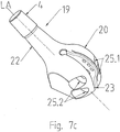
Fig. 7a bis 7c perspektivische Ansichten des Aufnahmekopfes nachFig. 6 und -
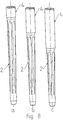
Fig. 8a bis 8c eine Ansicht der Nägel mit unterschiedlicher Länge. - Die
Fig. 1 zeigt den grundsätzlichen Aufbau der erfindungsgemäßen Gelenkprothese in einer ersten Ausführungsvariante in Explosionsdarstellung. Die erfindungsgemäße Gelenkprothese, die beispielsweise bei Resektionen aufgrund von Metastasen im Knochen, bei Hüft-Revisionen oder auch bei Infektionen bzw. Trauma eingesetzt wird, setzt sich aus einem entsprechend den biomechanischen Gegebenheiten der Anatomie des jeweiligen Patienten angepassten, gekrümmt ausgebildeten, einstückigen Kopfteil 1, einem Nagel 2, beispielsweise Femurnagel, und einem Verbindungsmodul 3 zusammen.
Auf dem konischen Zapfen 4 des Kopfteils 1 ist eine Gelenkkugel 5 aufsteckbar angeordnet, die in eine nicht dargestellte Gelenkpfanne eingreift. Das distale Ende des Kopfteils 1 ist zu einem zylindrischen Schaft 6 aus Vollmaterial ausgeformt und wird zur Befestigung in das später beschriebene Verbindungsmodul 3 eingeschoben.
Der Nagel 2 wird in den Knochenmarkkanal des nicht dargestellten Os longum eingebracht und verankert. Die Nägel 2 haben unterschiedliche Längen und sind anatomisch an die Kontur des Markkanals entsprechend angepasst. Sie sind durch Verriegelungsschrauben bzw. ein sternförmiges Profil ausreichend gegen Rotation im Markkanal gesichert. - Der Nagel 2 besitzt einen zylindrischen Nagelhals 7 aus Vollmaterial. Mit dem Nagel 2 ist der Schaft 6 des Kopfteils 1 mittels des Verbindungsmoduls 3 starr verbunden, das den Nagelhals 7 und den Schaft 6 jeweils manschettenförmig umfasst. Das Verbindungsmodul 3 ist - wie
Fig. 2 zeigt- zweiteilig und besteht aus zwei zylindrischen Halbschalen 8.1 und 8.2, die im Wesentlichen gleichartig ausgebildet sind. Beide Halbschalen 8.1 und 8.2 definieren im zusammengesetzten Zustand eine Durchführung 9, deren innere Wandung 10 eine senkrecht zur Längsachse LA des Moduls angeordnete Profilierung 11 besitzt. Jeweils vier nebeneinander liegende Ausnehmungen 12.1 und 12.2 sind in jede der Halbschalenwandung 13 so eingebracht, dass die Ausnehmungen koaxial zur Längsachse LA des Moduls 3 und senkrecht zu der von den Halbschalen 8.1 und 8.2 virtuell aufgespannten Teilungsebene TE angeordnet sind, so dass beispielsweise zum Verbindungsmodul 3 mindestens 8 Ausnehmungen gehören. In die Ausnehmungen 12.1 der Halbschale 8.2 ist ein Innengewinde 14 eingebracht, in das eine durch die Ausnehmung 12.1 der Halbschale 8.1 eingeführte Innensechskantschraube 15 eingeschraubt werden kann. - Die Halbschalen 8.1 und 8.2 bilden mit der jeweiligen Innensechskantschraube 15 und dem dazu korrespondierenden Innengewinde 14 ein spannbackenartiges Spannmittel 16, das sich beim Anziehen der Innensechskantschraube 15 um den zylinderförmigen Nagelhals 7 legt und zwischen der Profilierung 11 und dem Nagelhals 7 mehrere umfangsmäßig umlaufende linienartige Reibschlussverbindungen erzeugt. Der Außendurchmesser AD des Nagelhalses 7 ist dabei auf den Innendurchmesser ID der Durchführung 9 entsprechend abgestimmt.
Der Widerstand dieser Reibschlussverbindung gegen eine axiale oder eine Rotation der Komponenten lässt sich durch das Aufbringen eines definierten Anzugmomentes auf die Innensechskantschraube 15 sehr genau und exakt einstellen. Durch die Zuordnung von jeweils vier Spannmitteln 16 am Nagelhals 7 wird eine sichere Verbindung zwischen dem Nagel 2 und dem Kopfteil 1 erreicht.
Alle Spannmittel 16 sind nach ventral ausgerichtet und so bei einer späteren Revision problemlos von außen zugänglich, ohne große Bereiche des körpereigenen Gewebes traumatisieren zu müssen. - Die
Fig. 3a bis 3d zeigen verschiedene Verbindungsmodule 3.1 bis 3.4 mit unterschiedlichen Längen L, beispielsweise ein Verbindungsmodul 3.1 mit einer Länge L1Fig. 3a ), ein Verbindungsmodul 3.2 mit einer Länge L2 (Fig. 3b ), ein Verbindungsmodul 3.3 mit einer Länge L3 (Fig. 3c ), und ein Verbindungsmodul 3.4 mit einer Länge L4 (Fig. 3d ). Es versteht sich, dass auch die Längen der Verbindungsmodule nach den anatomischen Gegebenheiten der jeweiligen Patienten ausgewählt werden. - Die
Fig. 4 zeigt einen rundstabförmigen Modulverbinder 17, mit dessen Hilfe unterschiedlich lange oder gleichlange Verbindungsmodule 3.1 bis 3.4 aneinanderfügbar sind. Der Modulverbinder 17 besteht aus Vollmaterial, dessen Durchmesser DM auf den Innendurchmesser ID der Durchführung 9 abgestimmt ist. Der Modulverbinder 17 weist mittig einen umlaufenden Anschlag 18 mit einem Durchmesser DA auf, der gegenüber dem Innendurchmesser ID der Durchführung 9 größer ist. Durch Einschieben der jeweiligen Enden des Modulverbinders 17 in das entsprechende Ende der Durchführung 9 der jeweilig zu verbindenden Verbindungsmodule 3.1 bis 3.4 und Spannen der jeweilig zugehörenden Spannmittel 16 wird eine Reibschlussverbindung zwischen dem Modulverbinder 17 und den Verbindungsmodulen hergestellt. - Dadurch ist es möglich, die einzelnen Verbindungsmodule 3.1 bis 3.4 miteinander zu kombinieren und eine große Längenvariabilität zu erreichen.
- Das in
Fig. 3e und5 gezeigte Anschlag- oder Stützmodul 3.5 dient als eine in der Höhe einstellbare Abstützung gegenüber dem Os longum, beispielsweise Femur. - Die
Fig. 6 zeigt eine weitere Variante der erfindungsgemäßen Gelenkprothese in Explosionsdarstellung. Diese Gelenkprothese umfasst ein schaftartiges Halsstück 19 verhältnismäßig kurzer Länge und einen Nagel 2, beispielsweise Femurnagel. Das Wesentliche dieser Variante der Erfindung besteht darin, dass das in Beispiel 1 noch separate Verbindungsmodul 3 integraler Bestandteil des schaftartigen Halsstücks 19 wird, so dass nur noch insgesamt zwei Elemente die erfindungsgemäße Gelenkprothese bilden. - Wie im Beispiel 1 auch besitzt das Halsstück 19 einen konischen Zapfen 4, auf dem eine Gelenkkugel 5 aufsteckbar angeordnet ist, die in eine nicht dargestellte Gelenkpfanne eingreift. Das distale Ende des Halsstücks 19 ist zu einem helmartigen Aufnahmekopf 20 ausgeformt, der eine Einstecköffnung 21 zum Einführen des Nagelhalses 7 aufweist. Der Aufnahmekopf 20 ist mit einem in Richtung der Längsachse LA des Halsstücks 19 bis etwa in den Schaft 22 des Halsstücks 19 verlaufenden Schlitz 23 versehen. Dem Schlitz 23 sind in den Seitenwänden 24 jeweils zwei senkrecht zur Längsachse LA positionierte, zueinander korrespondierende Ausnehmungen 25.1 und 25.2 zur Aufnahme eines Spannmittels 26 zugeordnet, so dass sich auch der Antetorsionswinkel stufenlos einstellen lässt.
- Die innere Wandung 27 des Aufnahmekopfes 20 ist mit einer senkrecht zur Längsachse LA des Halsstücks 19 angeordnete Profilierung 28 versehen (siehe
Fig. 7a und7b ). - In die Ausnehmungen 25.1 und 25.2 der Seitenwände 24 ist ein Innengewinde 29 eingebracht, in das eine durch die Ausnehmung 25.1 eingeführte Innensechskantschraube 30 eingeschraubt werden kann.
- Die Ausnehmungen 25.1 und 25.2 mit ihrem Innengewinde 28 bilden mit der jeweiligen Innensechskantschraube 30 und dem Schlitz 23 das spannbackenartige Spannmittel 26, das sich beim Anziehen der Innensechskantschraube 30 um den zylinderförmigen Nagelhals 7 legt und zwischen der Profilierung 28 und dem Nagelhals 7 eine umfangsmäßig umlaufende linienartige Reibschlussverbindung erzeugt. Der Außendurchmesser AD des Nagelhalses 7 ist dabei auf den Innendurchmesser ID der Einstecköffnung 21 entsprechend abgestimmt.
Der Widerstand dieser Reibschlussverbindung gegen eine axiale oder eine Rotation der Komponenten lässt sich durch das Aufbringen eines definierten Anzugmomentes auf die Innensechskantschraube 30 sehr genau und exakt einstellen. Durch die Zuordnung von jeweils zwei Spannmitteln 26 am Nagelhals 7 wird eine sichere Verbindung zwischen dem Nagel 2 und dem Halsstück 19 erreicht.
Alle Spannmitteln 26 sind nach ventral ausgerichtet und so bei einer späteren Revision problemlos von außen zugänglich, ohne große Bereiche des körpereigenen Gewebes traumatisieren zu müssen. - Es gehört natürlich auch zur erfindungsgemäßen Lösung, wenn der in
Fig. 4 dargestellte Modulverbinder 17, dessen Außendurchmesser AD auf den Innendurchmesser der Einstecköffnung 21 abgestimmt ist, in die Einstecköffnung 21 des Aufnahmekopfes 20 geschoben wird und eine erweiterte Längenvariabilität der Gelenkprothese dadurch erreicht wird, dass der Nagelhals 7 des Nagel 2 und der Modulverbinder 17 durch verschieden lange Verbindungsmodule 3 (sieheFig. 3a-d ) verbunden werden. - Die
Fig. 8a bis c zeigen Beispiele von Nägeln mit unterschiedlicher Länge, deren Halsdurchmesser AD auf den Innendurchmesser ID der Durchführung 7 der jeweiligen Verbindungsmodule 3.1 bis 3.4 bzw. der Einstecköffnung 21 im Aufnahmekopf 20 abgestimmt sind. - Alle Teile der erfindungsgemäßen Gelenkprothese bestehen aus einem körperverträglichen und körperbeständigen metallischen Werkstoff. Die äußeren Oberflächen sind mit einer definierten Rauheit, beispielweise zwischen 20 µm und 80 µm versehen. Dies soll einerseits bei den Reibschlusspartnern den Reibkoeffizienten erhöhen und andererseits das Einwachsen des Implantats fördern.
- Die Erfindung beschränkt sich in ihrer Ausführung nicht auf die vorgenannten Ausführungsbeispiele. Vielmehr sind Varianten denkbar, welche von der dargestellten Lösung auch bei grundsätzlich anders gearteten Ausführungen abweichen können.
Bezugszeichenliste Kopfteil 1 Nagel 2 Verbindungsmodul 3, 3.1-3.4 Stütz- oder Anschlagmodul 3.5 Zapfen von 1 4 Gelenkkugel 5 Zylindrischer Schaft von 1 6 Nagelhals von 2 7 Halbschalen von 3 8.1, 8.2 Durchführung in 3 9 Innere Wandung von 3 10 Profilierung 11 Ausnehmungen 12.1, 12.2 Halbschalenwandung 13 Innengewinde 14 Innensechskantschraube 15 Spannmittel 16 Modulverbinder 17 Anschlag von 17 18 Schaftartiges Halsstück 19 Aufnahmekopf 20 Einstecköffnung in 20 21 Schaft von 19 22 Schlitz 23 Seitenwände von 19 24 Ausnehmung 25.1, 25.2 Spannmittel 26 Innere Wandung von 19 27 Profilierung 28 Innengewinde 29 Innensechskantschraube 30 Außendurchmesser von 18 DA Durchmesser von 17 DM Innendurchmesser von 9 ID Länge von 3, 3.1-3.4 L Längsachse von 3, 3.1-3.4 LA Teilungsebene von 3 TE
Claims (15)
- Modulare Gelenkprothese mit einem gekrümmt ausgebildeten Kopfteil, auf dessen konischen Zapfen eine aufsteckbare Gelenkkugel befestigt ist, und mit einem in den Knochenmarkkanal des Os longum einsetzbaren Nagel (2) mit einem Nagelhals (7), wobei zwischen Kopfteil (1) und Nagelhals (7) ein Verbindungsmittel vorgesehen ist, das das Kopfteil verdrehsicher hält, dadurch gekennzeichnet, dass das Verbindungsmittel mindestens ein in Achsrichtung des Nagels gelegenes manschettenartiges Modul (3, 3.1-3.4) mit mindestens zwei in Achsrichtung (LA) des Moduls (3, 3.1-3.4) geteilte, lösbar miteinander verbundene Halbschalen (8.1,8.2) umfasst, die miteinander eine sich axial erstreckende Durchführung (9) zum Einführen des Nagelhalses (7) in die Durchführung (9) ausbilden und die koaxial in Längsrichtung des Moduls (3) angeordnete, jeweils senkrecht zur Achse (LA) positionierte, zueinander korrespondierende Ausnehmungen (12.1,12.2) zur Aufnahme eines Spannmittels (16) aufweisen, das im gespannten Zustand den Nagelhals (7) in der Durchführung (9) ausschließlich mittels Reibschluss spannbackenartig mit einem gegen axiale Verschiebung und Rotation ausreichenden Anzugsmoment fixiert.
- Modulare Gelenkprothese mit einem schaftartig geformten Halsstück, auf dessen konischen Zapfen eine aufsteckbare Gelenkkugel befestigt ist, und mit in den Knochenmarkkanal des Os longum einsetzbaren Nagel (2) mit einem Nagelhals (7), wobei zwischen Halsstück (19) und Nagelhals (7) des Nagels ein Verbindungsmittel vorgesehen ist, das das Halsstück (19) in vorbestimmter Winkellage verdrehsicher hält, dadurch gekennzeichnet, dass das Halsstück (19) an seinem distalen Ende zu einem auf den Nagelhals (7) des Nagels aufsteckbaren helmförmigen Aufnahmekopf (20) ausgeformt ist, der eine Einstecköffnung (21) zum Einführen des Nagelhalses (7) oder eines Modulverbinder (17) aufweist, wobei der Kopf (20) mit einem in Richtung Längsachse (LA) des Halsstücks (19) bis etwa in den Schaft (22) verlaufenden Schlitz (23) versehen ist, dem jeweils senkrecht zur Achse (LA) positionierte, zueinander korrespondierende Ausnehmungen (25.1, 25.2) zur Aufnahme eines Spannmittels (26) zugeordnet sind, das im gespannten Zustand den Nagelhals (7) oder Modulverbinder (17) im Aufnahmekopf (20) des Halsstücks (19) ausschließlich mittels an sich bekanntem Reibschluss spannbackenartig mit einem gegen axiale Verschiebung und Rotation ausreichendes Anzugsmoment klemmend fixiert.
- Gelenkprothese nach Anspruch 2, dadurch gekennzeichnet, dass zum Verbinden von Modulen gleicher oder unterschiedlicher Länge (L) ein Modulverbinder (17) vorgesehen ist, dessen Aussendurchmesser (AD) auf den Innendurchmesser (ID) der Einstecköffnung (21) abgestimmt ist, und dass zum Verbinden des Modulverbinders (17) mit dem Nagel (2) zusätzlich ein manschettenartiges Modul (3, 3.1-3.4) mit mindestens zwei in Achsrichtung (LA) des Moduls (3) geteilte, lösbar miteinander verbundene Halbschalen (8.1, 8.2) vorgesehen ist, die miteinander eine sich axial erstreckende Durchführung (9) zum Einführen des Nagelhalses (7) in das eine Ende und des Modulverbinders (17) in das andere Ende der Durchführung (9) ausbilden und die koaxial in Längsrichtung des Moduls (3, 3.1-3.4) angeordnete, jeweils senkrecht zur Achse (LA) positionierte, zueinander korrespondierende Ausnehmungen (12.1, 12.2) zur Aufnahme des Spannmittels (16) aufweisen, das im gespannten Zustand den Nagelhals (7) und den Modulverbinder (17) in der Durchführung (9) ausschließlich mittels Reibschluss spannbackenartig mit einem gegen axiale Verschiebung und Rotation ausreichenden Anzugsmoment klemmend fixiert.
- Gelenkprothese nach Anspruch 1 oder 3, dadurch gekennzeichnet, dass das Modul (3, 3.1-3.4) im Wesentlichen eine zylindrische Form aufweist und die Halbschalen (8.1, 8.2) im Wesentlichen gleichartig ausgebildet sind.
- Gelenkprothese nach einem der Ansprüche 1, 3 und 4, dadurch gekennzeichnet, dass das Modul(3,3.1-3.4) längenvariabel ist und Module mit verschiedenen Längen miteinander kombinierbar sind.
- Gelenkprothese nach Anspruch 1, dadurch gekennzeichnet, dass zum Verbinden von Modulen (3, 3.1-3.4) gleicher oder unterschiedlicher Länge (L) ein Modulverbinder (17) vorgesehen ist, dessen Außendurchmesser (AD) auf den Innendurchmesser (ID) der Durchführung (9) oder der Einstecköffnung (21) abgestimmt ist.
- Gelenkprothese nach Anspruch 1 oder 2, dadurch gekennzeichnet, dass die Durchführung (9) oder die Einstecköffnung (21) an ihren Innenwandungen (10, 27) eine quer zur Längsrichtung (LA) des Moduls (3, 3.1-3.4) bzw. des Aufnahmekopfes (20) angeordnete Profilierung (11, 28) zum Verhindern von Mikrobewegungen, vorzugsweise Fretting, zwischen Nagelhals (7) und Modulverbinders (17) im Modul (3,3.1-3.4) bzw. in der Einstecköffnung (21) aufweist.
- Gelenkprothese nach Anspruch 3 oder 7, dadurch gekennzeichnet, dass der Modulverbinder (17) aus Vollmaterial besteht.
- Gelenkprothese nach Anspruch 1 oder 3, dadurch gekenzennzeichnet, dass der Durchmesser der Module (3, 1.1-3.4) unterschiedlicher Länge (L) gleich ist.
- Gelenkprothese nach Anspruch 1 oder 2, dadurch gekennzeichnet, dass die Spannmittel (16,26) aus einer Innensechskantschraube (15,30) und einem in der korrespondierenden Ausnehmung (12.1,12.2 bzw. 25.1, 25.2) vorgesehenen Innengewinde (14, 29) bestehen.
- Gelenkprothese nach Anspruch 10, dadurch gekennzeichnet, dass das Spannmittel (16, 26) durch Aufbringen eines bestimmten Anzugsmoments gegen Lösen gesichert ist.
- Gelenkprothese nach Anspruch 1 oder 2, dadurch gekennzeichnet, dass der Nagel (2) verschiedene Längen (L) aufweist, wobei der Durchmesser des Nagelhals der Nägel verschiedener Längen gleich ist.
- Gelenkprothese nach einem der Ansprüche 1 bis 12, dadurch gekennzeichnet, dass das Halsstück (19) mit und ohne Modul (3, 3.1-3.4) mit dem Nagel (2) unterschiedlicher Länge kombinierbar ist.
- Gelenkprothese nach Anspruch 1 bis 13, dadurch gekennzeichnet, dass alle Teile der Prothese aus einer biokompatiblen Legierung, vorzugsweise eine Titanlegierung, bestehen.
- Gelenkprothese nach Anspruch 1 bis 13, dadurch gekennzeichnet, dass alle Teile der Prothese eine raue Oberfläche zur Förderung des Anwachsens des Knochens aufweist.
Applications Claiming Priority (2)
| Application Number | Priority Date | Filing Date | Title |
|---|---|---|---|
| DE102008049123A DE102008049123B4 (de) | 2008-09-26 | 2008-09-26 | Modulare Gelenkprothese |
| PCT/DE2009/001272 WO2010034284A1 (de) | 2008-09-26 | 2009-09-11 | Modulare gelenkprothese |
Publications (2)
| Publication Number | Publication Date |
|---|---|
| EP2349110A1 EP2349110A1 (de) | 2011-08-03 |
| EP2349110B1 true EP2349110B1 (de) | 2017-02-08 |
Family
ID=41531767
Family Applications (1)
| Application Number | Title | Priority Date | Filing Date |
|---|---|---|---|
| EP09737333.6A Not-in-force EP2349110B1 (de) | 2008-09-26 | 2009-09-11 | Modulare gelenkprothese |
Country Status (5)
| Country | Link |
|---|---|
| US (2) | US8518122B2 (de) |
| EP (1) | EP2349110B1 (de) |
| DE (1) | DE102008049123B4 (de) |
| ES (1) | ES2622141T3 (de) |
| WO (1) | WO2010034284A1 (de) |
Families Citing this family (12)
| Publication number | Priority date | Publication date | Assignee | Title |
|---|---|---|---|---|
| DE102008049123B4 (de) * | 2008-09-26 | 2013-06-06 | Merete Medical Gmbh | Modulare Gelenkprothese |
| US8444699B2 (en) * | 2010-02-18 | 2013-05-21 | Biomet Manufacturing Corp. | Method and apparatus for augmenting bone defects |
| DE102010028430B4 (de) * | 2010-04-30 | 2016-11-10 | ESKA Medical Produktion Lübeck GmbH kurz ESKA MPL GmbH | Implantat als Knochenersatz mit einer seine Oberfläche zumindest teilweise bedeckenden offenmaschigen, dreidimensionalen Raumnetzstruktur |
| DE102012001395A1 (de) * | 2012-01-26 | 2013-08-01 | Merete Medical Gmbh | Adapter-System für eine Endoprothese |
| US9216086B2 (en) * | 2012-02-01 | 2015-12-22 | Zimmer, Inc. | Adjustable provisional component of a medical device |
| DE102013101325B4 (de) | 2013-02-11 | 2016-11-17 | Merete Medical Gmbh | Zwischenkörper für eine Endoprothese und Endoprothesenanordnung |
| US20150374503A1 (en) * | 2014-06-30 | 2015-12-31 | Bacterin International, Inc. | Implant for fusion between adjacent bone bodies |
| DE102015202715B4 (de) * | 2015-02-13 | 2016-12-15 | Waldemar Link Gmbh & Co. Kg | Gelenkinterimsprothese |
| US9597203B2 (en) | 2015-03-25 | 2017-03-21 | Tornier, Inc. | Modular humeral implant |
| EP3498230B1 (de) * | 2017-12-15 | 2020-10-28 | Waldemar Link GmbH & Co. KG | Modulares endoprothesen-schaftsystem mit rotationselement |
| EP3932369B1 (de) * | 2020-06-03 | 2025-06-04 | Howmedica Osteonics Corp. | Eingeschobene endoprothese |
| EP4482410A4 (de) * | 2022-02-25 | 2026-03-04 | Orit Yahalom | Knochenfixiervorrichtung |
Citations (1)
| Publication number | Priority date | Publication date | Assignee | Title |
|---|---|---|---|---|
| DE102008045291A1 (de) * | 2008-09-02 | 2010-03-04 | Merete Medical Gmbh | Kniearthrodese-Implantat |
Family Cites Families (47)
| Publication number | Priority date | Publication date | Assignee | Title |
|---|---|---|---|---|
| DE2340546A1 (de) * | 1973-08-10 | 1975-02-27 | Pfaudler Werke Ag | Metallisches implantat und verfahren zu seiner herstellung |
| US4179758A (en) * | 1976-04-29 | 1979-12-25 | Howmedica, Inc. | Fixation stem for prosthetic device |
| US4578081A (en) * | 1982-02-17 | 1986-03-25 | Howmedica International, Inc. | Bone prosthesis |
| DE8306663U1 (de) | 1983-03-04 | 1986-07-31 | Mecron Medizinische Produkte Gmbh, 1000 Berlin | Implantat |
| DE3340767A1 (de) | 1983-11-08 | 1985-05-15 | Mecron Medizinische Produkte Gmbh, 1000 Berlin | Bausatz fuer eine resektionsprothese |
| US4846839A (en) * | 1984-02-09 | 1989-07-11 | Joint Medical Products Corporation | Apparatus for affixing a prosthesis to bone |
| FR2575059B1 (fr) * | 1984-12-21 | 1988-11-10 | Daher Youssef | Dispositif d'etaiement utilisable dans une prothese vertebrale |
| US4790852A (en) * | 1986-09-15 | 1988-12-13 | Joint Medical Products Corporation | Sleeves for affixing artificial joints to bone |
| US4938768A (en) * | 1987-03-09 | 1990-07-03 | Henry Ford Hospital | Bone gap bridging and fusing device |
| DE8903850U1 (de) | 1989-03-21 | 1989-06-01 | orthoplant Endoprothetik GmbH, 2800 Bremen | Oberschenkelteil für eine Hüftendoprothese |
| FR2670108A1 (fr) | 1990-12-06 | 1992-06-12 | Erato | Element femoral pour prothese de hanche. |
| US5108393A (en) * | 1991-04-08 | 1992-04-28 | The United States Of America As Represented By The Secretary Of The Navy | Non-invasive body-clamp |
| US5658349A (en) | 1991-07-29 | 1997-08-19 | Joint Medical Products Corporation | Prosthetic joint system for bone replacement |
| US5352227A (en) * | 1993-02-03 | 1994-10-04 | Howmedica Inc. | Intercalary device |
| US5626580A (en) * | 1994-07-15 | 1997-05-06 | Brosnahan; Robert | Multi-section intramedullary nail |
| DE4442205A1 (de) * | 1994-11-19 | 1996-05-23 | Artos Med Produkte | Modulare Hüftgelenkprothese |
| US6217620B1 (en) * | 1995-09-29 | 2001-04-17 | Joon B. Park | Reinforcing an orthopedic implant |
| DE19633865A1 (de) * | 1996-08-16 | 1998-02-19 | Guenter Prof Dr Med Lob | Endoprothese |
| US5906644A (en) * | 1996-08-30 | 1999-05-25 | Powell; Douglas Hunter | Adjustable modular orthopedic implant |
| DE19722389C2 (de) | 1997-05-28 | 1999-07-01 | Eska Implants Gmbh & Co | Modulares Knie-Arthrodeseimplantat |
| US6428578B2 (en) * | 1998-03-18 | 2002-08-06 | Sct Incorporated | Modular prosthesis and connector therefor |
| US6264699B1 (en) | 1998-11-23 | 2001-07-24 | Depuy Orthopaedics, Inc. | Modular stem and sleeve prosthesis |
| US6280446B1 (en) * | 1999-10-28 | 2001-08-28 | Armand N. Blackmore | Tubular splint |
| US6299648B1 (en) * | 2000-03-17 | 2001-10-09 | Hammill Manufacturing Co. | Locking hip prosthesis |
| US6613092B1 (en) * | 2000-07-19 | 2003-09-02 | Centerpulse Orthopedics Inc. | Stem taper adapter |
| JP4223802B2 (ja) * | 2000-07-20 | 2009-02-12 | デピュイ・オーソピーディクス・インコーポレーテッド | 腰関節人工装具用のモジュラー式大腿骨軸部構成要素 |
| DE10036985A1 (de) * | 2000-07-29 | 2002-02-07 | Klaus Draenert | Schuhlöffelprothese |
| US6706072B2 (en) * | 2000-11-08 | 2004-03-16 | Depuy Orthopaedics, Inc. | Modular prosthesis having a stem component with a counterbored cavity defined therein and associated method |
| US6440171B1 (en) * | 2001-02-27 | 2002-08-27 | Hammill Manuf. Co. | Double D key locking prosthesis |
| US6355068B1 (en) * | 2001-06-07 | 2002-03-12 | Hammill Manufacturing Co. | Sight gauge modular joint and method |
| US6692530B2 (en) * | 2001-10-17 | 2004-02-17 | Hammill Manufacturing Co. | Split sleeve modular joint |
| US6746487B2 (en) * | 2002-03-06 | 2004-06-08 | Smith & Nephew, Inc. | Intramedullary trial fixation device |
| US6981991B2 (en) * | 2002-06-27 | 2006-01-03 | Ferree Bret A | Arthroplasty devices configured to reduce shear stress |
| US6786932B1 (en) * | 2002-11-11 | 2004-09-07 | Armand N. Blackmore | Femur end implant |
| US6866683B2 (en) * | 2002-12-13 | 2005-03-15 | Medicine Lodge, Inc. | Modular implant for joint reconstruction and method of use |
| US7235106B2 (en) * | 2002-12-20 | 2007-06-26 | Depuy Products, Inc. | Modular hip stems and associated method of trialing |
| GB0305449D0 (en) * | 2003-03-10 | 2003-04-16 | Benoist Girard Sas | Femoral prosthesis |
| US7468078B2 (en) * | 2003-07-03 | 2008-12-23 | Zimmer, Inc. | Modular hip prosthesis |
| US7435263B2 (en) * | 2003-09-30 | 2008-10-14 | Depuy Products, Inc. | Modular long bone prosthesis for partial or total bone replacement |
| FR2861577B1 (fr) | 2003-11-05 | 2006-02-10 | Ceravic | Orthese implantable et kit chirurgical pour l'arthrodese du genou |
| DE202004015578U1 (de) | 2004-10-07 | 2004-12-23 | Merete Medical Gmbh | Vorrichtung zur Stabilisierung von Frakturen |
| AU2005316640B2 (en) * | 2004-12-17 | 2011-06-09 | Depuy Products, Inc. | Modular diaphyseal and collar implant |
| US7998218B1 (en) * | 2005-02-02 | 2011-08-16 | Biomet Manufacturing Corp. | Modular orthopedic implant |
| US7776098B2 (en) * | 2006-10-12 | 2010-08-17 | Murphy Stephen B | Modular femoral prosthesis with on-axis junction |
| US20090171463A1 (en) * | 2007-12-28 | 2009-07-02 | Peter Brehm | Arthrodesis module and method for providing a patient with an arthrodesis |
| DE102008049123B4 (de) * | 2008-09-26 | 2013-06-06 | Merete Medical Gmbh | Modulare Gelenkprothese |
| US8758446B2 (en) * | 2009-03-23 | 2014-06-24 | Biomet Manufacturing, Llc | Method and apparatus for protecting modular implant connection |
-
2008
- 2008-09-26 DE DE102008049123A patent/DE102008049123B4/de not_active Expired - Fee Related
-
2009
- 2009-09-11 ES ES09737333.6T patent/ES2622141T3/es active Active
- 2009-09-11 US US13/120,628 patent/US8518122B2/en active Active
- 2009-09-11 EP EP09737333.6A patent/EP2349110B1/de not_active Not-in-force
- 2009-09-11 WO PCT/DE2009/001272 patent/WO2010034284A1/de not_active Ceased
-
2013
- 2013-06-24 US US13/925,342 patent/US9233000B2/en not_active Expired - Fee Related
Patent Citations (1)
| Publication number | Priority date | Publication date | Assignee | Title |
|---|---|---|---|---|
| DE102008045291A1 (de) * | 2008-09-02 | 2010-03-04 | Merete Medical Gmbh | Kniearthrodese-Implantat |
Also Published As
| Publication number | Publication date |
|---|---|
| ES2622141T3 (es) | 2017-07-05 |
| US20130289739A1 (en) | 2013-10-31 |
| US20110196503A1 (en) | 2011-08-11 |
| WO2010034284A1 (de) | 2010-04-01 |
| US8518122B2 (en) | 2013-08-27 |
| WO2010034284A9 (de) | 2011-05-26 |
| DE102008049123B4 (de) | 2013-06-06 |
| EP2349110A1 (de) | 2011-08-03 |
| US9233000B2 (en) | 2016-01-12 |
| DE102008049123A1 (de) | 2010-04-15 |
Similar Documents
| Publication | Publication Date | Title |
|---|---|---|
| EP2328518B1 (de) | Kniearthrodese- implantat | |
| DE102008049123B4 (de) | Modulare Gelenkprothese | |
| DE602004007219T2 (de) | Implantierbare Orthese und chirurgischer Satz für eine Arthrodese des Knies | |
| EP1642552B1 (de) | Endoprothese für ein Metatarsophalangealgelenk | |
| EP0792127B1 (de) | Gelenkprothese | |
| EP1024762B1 (de) | Knochenfixationsvorrichtung | |
| DE69925443T2 (de) | Modulare Prothese mit Schaft und Hülse | |
| DE60218686T2 (de) | Modulare prothetische gelenkpfanne | |
| EP0792129B1 (de) | Modulare gelenkprothese | |
| EP1093777B1 (de) | Schulter-Endoprothese | |
| DE112004001893B4 (de) | Kegelförmige Gelenksprothese | |
| DE202005019487U1 (de) | Facettengelenkprothese | |
| EP1663031A1 (de) | Längsträger | |
| EP2394606A1 (de) | Prothese zum teilweisen Ersatz eines Röhrenknochens | |
| DE202005020876U1 (de) | Endoprothese für ein Schultergelenk | |
| DE4031520A1 (de) | Verlaengerbare endoprothese | |
| DE102019000965B4 (de) | Knochenverankerungsvorrichtung für den Pedikelzugang | |
| WO1990012547A1 (de) | Fixierungssystem für röhrenknochenfrakturen | |
| DE102021004940A1 (de) | Vorrichtung zur Behandlung von Frakturen | |
| EP2846738B1 (de) | Verstärkungsimplantat für einen langgestreckten knochen, insbesondere femur | |
| EP2806830B1 (de) | Adapter-system für eine endoprothese | |
| CH664686A5 (en) | Elbow joint prosthesis - has head parts of prosthesis anchored in bone cavities by perforated tubes | |
| DE9418963U1 (de) | Bausatz für eine modulare Hüftgelenkprothese | |
| DE10221965A1 (de) | Schenkelhalsendoprothese | |
| DE102005001255B4 (de) | Inverse Schultergelenk-Endoprothese mit einteiligem Mittelteil |
Legal Events
| Date | Code | Title | Description |
|---|---|---|---|
| PUAI | Public reference made under article 153(3) epc to a published international application that has entered the european phase |
Free format text: ORIGINAL CODE: 0009012 |
|
| 17P | Request for examination filed |
Effective date: 20110329 |
|
| AK | Designated contracting states |
Kind code of ref document: A1 Designated state(s): AT BE BG CH CY CZ DE DK EE ES FI FR GB GR HR HU IE IS IT LI LT LU LV MC MK MT NL NO PL PT RO SE SI SK SM TR |
|
| DAX | Request for extension of the european patent (deleted) | ||
| 17Q | First examination report despatched |
Effective date: 20140709 |
|
| GRAP | Despatch of communication of intention to grant a patent |
Free format text: ORIGINAL CODE: EPIDOSNIGR1 |
|
| INTG | Intention to grant announced |
Effective date: 20160929 |
|
| GRAS | Grant fee paid |
Free format text: ORIGINAL CODE: EPIDOSNIGR3 |
|
| GRAA | (expected) grant |
Free format text: ORIGINAL CODE: 0009210 |
|
| RAP1 | Party data changed (applicant data changed or rights of an application transferred) |
Owner name: ARISTOTECH INDUSTRIES GMBH |
|
| AK | Designated contracting states |
Kind code of ref document: B1 Designated state(s): AT BE BG CH CY CZ DE DK EE ES FI FR GB GR HR HU IE IS IT LI LT LU LV MC MK MT NL NO PL PT RO SE SI SK SM TR |
|
| REG | Reference to a national code |
Ref country code: GB Ref legal event code: FG4D Free format text: NOT ENGLISH |
|
| REG | Reference to a national code |
Ref country code: CH Ref legal event code: EP Ref country code: AT Ref legal event code: REF Ref document number: 866554 Country of ref document: AT Kind code of ref document: T Effective date: 20170215 |
|
| REG | Reference to a national code |
Ref country code: IE Ref legal event code: FG4D Free format text: LANGUAGE OF EP DOCUMENT: GERMAN |
|
| REG | Reference to a national code |
Ref country code: DE Ref legal event code: R096 Ref document number: 502009013629 Country of ref document: DE |
|
| REG | Reference to a national code |
Ref country code: LT Ref legal event code: MG4D |
|
| REG | Reference to a national code |
Ref country code: NL Ref legal event code: MP Effective date: 20170208 |
|
| REG | Reference to a national code |
Ref country code: ES Ref legal event code: FG2A Ref document number: 2622141 Country of ref document: ES Kind code of ref document: T3 Effective date: 20170705 |
|
| PG25 | Lapsed in a contracting state [announced via postgrant information from national office to epo] |
Ref country code: GR Free format text: LAPSE BECAUSE OF FAILURE TO SUBMIT A TRANSLATION OF THE DESCRIPTION OR TO PAY THE FEE WITHIN THE PRESCRIBED TIME-LIMIT Effective date: 20170509 Ref country code: HR Free format text: LAPSE BECAUSE OF FAILURE TO SUBMIT A TRANSLATION OF THE DESCRIPTION OR TO PAY THE FEE WITHIN THE PRESCRIBED TIME-LIMIT Effective date: 20170208 Ref country code: FI Free format text: LAPSE BECAUSE OF FAILURE TO SUBMIT A TRANSLATION OF THE DESCRIPTION OR TO PAY THE FEE WITHIN THE PRESCRIBED TIME-LIMIT Effective date: 20170208 Ref country code: NO Free format text: LAPSE BECAUSE OF FAILURE TO SUBMIT A TRANSLATION OF THE DESCRIPTION OR TO PAY THE FEE WITHIN THE PRESCRIBED TIME-LIMIT Effective date: 20170508 Ref country code: LT Free format text: LAPSE BECAUSE OF FAILURE TO SUBMIT A TRANSLATION OF THE DESCRIPTION OR TO PAY THE FEE WITHIN THE PRESCRIBED TIME-LIMIT Effective date: 20170208 |
|
| PG25 | Lapsed in a contracting state [announced via postgrant information from national office to epo] |
Ref country code: LV Free format text: LAPSE BECAUSE OF FAILURE TO SUBMIT A TRANSLATION OF THE DESCRIPTION OR TO PAY THE FEE WITHIN THE PRESCRIBED TIME-LIMIT Effective date: 20170208 Ref country code: SE Free format text: LAPSE BECAUSE OF FAILURE TO SUBMIT A TRANSLATION OF THE DESCRIPTION OR TO PAY THE FEE WITHIN THE PRESCRIBED TIME-LIMIT Effective date: 20170208 Ref country code: NL Free format text: LAPSE BECAUSE OF FAILURE TO SUBMIT A TRANSLATION OF THE DESCRIPTION OR TO PAY THE FEE WITHIN THE PRESCRIBED TIME-LIMIT Effective date: 20170208 Ref country code: PT Free format text: LAPSE BECAUSE OF FAILURE TO SUBMIT A TRANSLATION OF THE DESCRIPTION OR TO PAY THE FEE WITHIN THE PRESCRIBED TIME-LIMIT Effective date: 20170608 Ref country code: BG Free format text: LAPSE BECAUSE OF FAILURE TO SUBMIT A TRANSLATION OF THE DESCRIPTION OR TO PAY THE FEE WITHIN THE PRESCRIBED TIME-LIMIT Effective date: 20170508 |
|
| REG | Reference to a national code |
Ref country code: FR Ref legal event code: PLFP Year of fee payment: 9 |
|
| PG25 | Lapsed in a contracting state [announced via postgrant information from national office to epo] |
Ref country code: EE Free format text: LAPSE BECAUSE OF FAILURE TO SUBMIT A TRANSLATION OF THE DESCRIPTION OR TO PAY THE FEE WITHIN THE PRESCRIBED TIME-LIMIT Effective date: 20170208 Ref country code: SK Free format text: LAPSE BECAUSE OF FAILURE TO SUBMIT A TRANSLATION OF THE DESCRIPTION OR TO PAY THE FEE WITHIN THE PRESCRIBED TIME-LIMIT Effective date: 20170208 Ref country code: CZ Free format text: LAPSE BECAUSE OF FAILURE TO SUBMIT A TRANSLATION OF THE DESCRIPTION OR TO PAY THE FEE WITHIN THE PRESCRIBED TIME-LIMIT Effective date: 20170208 Ref country code: RO Free format text: LAPSE BECAUSE OF FAILURE TO SUBMIT A TRANSLATION OF THE DESCRIPTION OR TO PAY THE FEE WITHIN THE PRESCRIBED TIME-LIMIT Effective date: 20170208 |
|
| REG | Reference to a national code |
Ref country code: DE Ref legal event code: R097 Ref document number: 502009013629 Country of ref document: DE |
|
| PG25 | Lapsed in a contracting state [announced via postgrant information from national office to epo] |
Ref country code: PL Free format text: LAPSE BECAUSE OF FAILURE TO SUBMIT A TRANSLATION OF THE DESCRIPTION OR TO PAY THE FEE WITHIN THE PRESCRIBED TIME-LIMIT Effective date: 20170208 Ref country code: DK Free format text: LAPSE BECAUSE OF FAILURE TO SUBMIT A TRANSLATION OF THE DESCRIPTION OR TO PAY THE FEE WITHIN THE PRESCRIBED TIME-LIMIT Effective date: 20170208 Ref country code: SM Free format text: LAPSE BECAUSE OF FAILURE TO SUBMIT A TRANSLATION OF THE DESCRIPTION OR TO PAY THE FEE WITHIN THE PRESCRIBED TIME-LIMIT Effective date: 20170208 |
|
| PLBE | No opposition filed within time limit |
Free format text: ORIGINAL CODE: 0009261 |
|
| STAA | Information on the status of an ep patent application or granted ep patent |
Free format text: STATUS: NO OPPOSITION FILED WITHIN TIME LIMIT |
|
| 26N | No opposition filed |
Effective date: 20171109 |
|
| REG | Reference to a national code |
Ref country code: DE Ref legal event code: R082 Ref document number: 502009013629 Country of ref document: DE |
|
| PG25 | Lapsed in a contracting state [announced via postgrant information from national office to epo] |
Ref country code: SI Free format text: LAPSE BECAUSE OF FAILURE TO SUBMIT A TRANSLATION OF THE DESCRIPTION OR TO PAY THE FEE WITHIN THE PRESCRIBED TIME-LIMIT Effective date: 20170208 |
|
| REG | Reference to a national code |
Ref country code: CH Ref legal event code: PL |
|
| PG25 | Lapsed in a contracting state [announced via postgrant information from national office to epo] |
Ref country code: MC Free format text: LAPSE BECAUSE OF FAILURE TO SUBMIT A TRANSLATION OF THE DESCRIPTION OR TO PAY THE FEE WITHIN THE PRESCRIBED TIME-LIMIT Effective date: 20170208 |
|
| REG | Reference to a national code |
Ref country code: IE Ref legal event code: MM4A |
|
| REG | Reference to a national code |
Ref country code: BE Ref legal event code: MM Effective date: 20170930 |
|
| PG25 | Lapsed in a contracting state [announced via postgrant information from national office to epo] |
Ref country code: LU Free format text: LAPSE BECAUSE OF NON-PAYMENT OF DUE FEES Effective date: 20170911 |
|
| PG25 | Lapsed in a contracting state [announced via postgrant information from national office to epo] |
Ref country code: LI Free format text: LAPSE BECAUSE OF NON-PAYMENT OF DUE FEES Effective date: 20170930 Ref country code: CH Free format text: LAPSE BECAUSE OF NON-PAYMENT OF DUE FEES Effective date: 20170930 Ref country code: IE Free format text: LAPSE BECAUSE OF NON-PAYMENT OF DUE FEES Effective date: 20170911 |
|
| REG | Reference to a national code |
Ref country code: FR Ref legal event code: PLFP Year of fee payment: 10 |
|
| PG25 | Lapsed in a contracting state [announced via postgrant information from national office to epo] |
Ref country code: BE Free format text: LAPSE BECAUSE OF NON-PAYMENT OF DUE FEES Effective date: 20170930 |
|
| PG25 | Lapsed in a contracting state [announced via postgrant information from national office to epo] |
Ref country code: MT Free format text: LAPSE BECAUSE OF FAILURE TO SUBMIT A TRANSLATION OF THE DESCRIPTION OR TO PAY THE FEE WITHIN THE PRESCRIBED TIME-LIMIT Effective date: 20170208 |
|
| REG | Reference to a national code |
Ref country code: AT Ref legal event code: MM01 Ref document number: 866554 Country of ref document: AT Kind code of ref document: T Effective date: 20170911 |
|
| PG25 | Lapsed in a contracting state [announced via postgrant information from national office to epo] |
Ref country code: AT Free format text: LAPSE BECAUSE OF NON-PAYMENT OF DUE FEES Effective date: 20170911 |
|
| PG25 | Lapsed in a contracting state [announced via postgrant information from national office to epo] |
Ref country code: HU Free format text: LAPSE BECAUSE OF FAILURE TO SUBMIT A TRANSLATION OF THE DESCRIPTION OR TO PAY THE FEE WITHIN THE PRESCRIBED TIME-LIMIT; INVALID AB INITIO Effective date: 20090911 |
|
| PG25 | Lapsed in a contracting state [announced via postgrant information from national office to epo] |
Ref country code: CY Free format text: LAPSE BECAUSE OF NON-PAYMENT OF DUE FEES Effective date: 20170208 |
|
| PG25 | Lapsed in a contracting state [announced via postgrant information from national office to epo] |
Ref country code: MK Free format text: LAPSE BECAUSE OF FAILURE TO SUBMIT A TRANSLATION OF THE DESCRIPTION OR TO PAY THE FEE WITHIN THE PRESCRIBED TIME-LIMIT Effective date: 20170208 |
|
| PG25 | Lapsed in a contracting state [announced via postgrant information from national office to epo] |
Ref country code: TR Free format text: LAPSE BECAUSE OF FAILURE TO SUBMIT A TRANSLATION OF THE DESCRIPTION OR TO PAY THE FEE WITHIN THE PRESCRIBED TIME-LIMIT Effective date: 20170208 |
|
| PG25 | Lapsed in a contracting state [announced via postgrant information from national office to epo] |
Ref country code: IS Free format text: LAPSE BECAUSE OF FAILURE TO SUBMIT A TRANSLATION OF THE DESCRIPTION OR TO PAY THE FEE WITHIN THE PRESCRIBED TIME-LIMIT Effective date: 20170608 |
|
| PGFP | Annual fee paid to national office [announced via postgrant information from national office to epo] |
Ref country code: IT Payment date: 20210827 Year of fee payment: 13 Ref country code: FR Payment date: 20210915 Year of fee payment: 13 |
|
| PGFP | Annual fee paid to national office [announced via postgrant information from national office to epo] |
Ref country code: DE Payment date: 20211007 Year of fee payment: 13 Ref country code: ES Payment date: 20211014 Year of fee payment: 13 Ref country code: GB Payment date: 20211029 Year of fee payment: 13 |
|
| REG | Reference to a national code |
Ref country code: DE Ref legal event code: R119 Ref document number: 502009013629 Country of ref document: DE |
|
| GBPC | Gb: european patent ceased through non-payment of renewal fee |
Effective date: 20220911 |
|
| PG25 | Lapsed in a contracting state [announced via postgrant information from national office to epo] |
Ref country code: FR Free format text: LAPSE BECAUSE OF NON-PAYMENT OF DUE FEES Effective date: 20220930 Ref country code: DE Free format text: LAPSE BECAUSE OF NON-PAYMENT OF DUE FEES Effective date: 20230401 |
|
| REG | Reference to a national code |
Ref country code: ES Ref legal event code: FD2A Effective date: 20231027 |
|
| PG25 | Lapsed in a contracting state [announced via postgrant information from national office to epo] |
Ref country code: IT Free format text: LAPSE BECAUSE OF NON-PAYMENT OF DUE FEES Effective date: 20220911 Ref country code: GB Free format text: LAPSE BECAUSE OF NON-PAYMENT OF DUE FEES Effective date: 20220911 |
|
| PG25 | Lapsed in a contracting state [announced via postgrant information from national office to epo] |
Ref country code: ES Free format text: LAPSE BECAUSE OF NON-PAYMENT OF DUE FEES Effective date: 20220912 |
|
| PG25 | Lapsed in a contracting state [announced via postgrant information from national office to epo] |
Ref country code: ES Free format text: LAPSE BECAUSE OF NON-PAYMENT OF DUE FEES Effective date: 20220912 |