EP2348944B2 - Pumpe für fluide - Google Patents
Pumpe für fluide Download PDFInfo
- Publication number
- EP2348944B2 EP2348944B2 EP09778692.5A EP09778692A EP2348944B2 EP 2348944 B2 EP2348944 B2 EP 2348944B2 EP 09778692 A EP09778692 A EP 09778692A EP 2348944 B2 EP2348944 B2 EP 2348944B2
- Authority
- EP
- European Patent Office
- Prior art keywords
- pump
- heating
- electrical appliance
- conveyor
- domestic electrical
- Prior art date
- Legal status (The legal status is an assumption and is not a legal conclusion. Google has not performed a legal analysis and makes no representation as to the accuracy of the status listed.)
- Active
Links
Images
Classifications
-
- D—TEXTILES; PAPER
- D06—TREATMENT OF TEXTILES OR THE LIKE; LAUNDERING; FLEXIBLE MATERIALS NOT OTHERWISE PROVIDED FOR
- D06F—LAUNDERING, DRYING, IRONING, PRESSING OR FOLDING TEXTILE ARTICLES
- D06F39/00—Details of washing machines not specific to a single type of machines covered by groups D06F9/00 - D06F27/00
- D06F39/04—Heating arrangements
-
- A—HUMAN NECESSITIES
- A47—FURNITURE; DOMESTIC ARTICLES OR APPLIANCES; COFFEE MILLS; SPICE MILLS; SUCTION CLEANERS IN GENERAL
- A47L—DOMESTIC WASHING OR CLEANING; SUCTION CLEANERS IN GENERAL
- A47L15/00—Washing or rinsing machines for crockery or tableware
- A47L15/42—Details
- A47L15/4214—Water supply, recirculation or discharge arrangements; Devices therefor
- A47L15/4225—Arrangements or adaption of recirculation or discharge pumps
-
- A—HUMAN NECESSITIES
- A47—FURNITURE; DOMESTIC ARTICLES OR APPLIANCES; COFFEE MILLS; SPICE MILLS; SUCTION CLEANERS IN GENERAL
- A47L—DOMESTIC WASHING OR CLEANING; SUCTION CLEANERS IN GENERAL
- A47L15/00—Washing or rinsing machines for crockery or tableware
- A47L15/42—Details
- A47L15/4285—Water-heater arrangements
-
- D—TEXTILES; PAPER
- D06—TREATMENT OF TEXTILES OR THE LIKE; LAUNDERING; FLEXIBLE MATERIALS NOT OTHERWISE PROVIDED FOR
- D06F—LAUNDERING, DRYING, IRONING, PRESSING OR FOLDING TEXTILE ARTICLES
- D06F39/00—Details of washing machines not specific to a single type of machines covered by groups D06F9/00 - D06F27/00
- D06F39/08—Liquid supply or discharge arrangements
- D06F39/083—Liquid discharge or recirculation arrangements
- D06F39/085—Arrangements or adaptations of pumps
Definitions
- the invention relates to an electrical household appliance with a pump or a water-bearing household appliance with a pump, such as a dishwasher, a washing machine or a tumble dryer.
- Similar electrical household appliances are, for example, from the WO 2006/136819 A1 known.
- a dishwasher or a washing machine can be operated with such a pump for introducing and heating water into the interior during operation.
- a whirlpool with a heated pump is known in accordance with figure 1 an impeller is always provided for conveying liquid.
- a fan is also provided in a housing of a motor as a conveyor for air, which is also seated on the same motor shaft and serves to cool a drive circuit and the motor.
- a pump is thus shown which can be used to pump both air and water.
- two conveyors are provided for this purpose, namely a conveyor for water and a conveyor for air.
- Another pump, for a whirlpool tub is from the US4858255A known.
- a single drive motor drives a pump to circulate water with reheating.
- the same pump drive motor also carries a separate conveyor for air, which is pumped into a tub containing the water to create the aerobatic effect.
- a dishwasher device is known with a centrifugal pump which is driven by a motor via a clutch.
- a single pipe leads into the centrifugal pump, which can suck in either air or water through an upstream three-way valve.
- a heating chamber with heating pipes is provided in front of the three-way tap to heat the drawn-in water. From the centrifugal pump, a single riser pipe goes up and away for the pumped fluid.
- a dishwashing machine with a pump at the bottom of the washing chamber which has a single conveyor. Water or air can be sucked in through a single central suction opening and pumped on to two pipelines in the same way.
- a heating device is arranged in front of the pump for heating the sucked-in fluid.
- a dishwashing machine is known with a pump at the bottom of a washing chamber having a single conveyor. Water can be heated in the bottom of the rinsing chamber by means of a heater and pumped further by the pump.
- centrifugal pumps can have impellers with adjustable blades. Depending on the complexity of the design, the blades can be adjusted either at a standstill or during operation.
- a pump housing for a pump for a dishwasher that has a tubular heater for heating.
- the tubular heating element either runs around a central suction opening on the outside or is arranged underneath an underside of a pump chamber.
- a thin film heating element is known. This can be used in a dishwasher, for example.
- a dishwasher which has a pump with a motor.
- the invention is based on the object of creating an electrical household appliance as mentioned at the outset, which has expanded operating and application options, is versatile and enables a particularly advantageous construction of an electrical household appliance such as a dishwasher, a tumble dryer or a washing machine.
- the pump arranged in such an electrical household appliance and a single conveyor of the pump, which is driven by the drive motor are designed in such a way that both water and air can be pumped or conveyed.
- an operating mode of the pump or the drive motor can be varied such that the speed, in particular the nominal operating speed, is correspondingly different, in particular a high nominal operating speed when pumping air and a lower nominal operating speed when pumping Water.
- This possible combined operation of the pump or these two uses can advantageously be used in a dishwasher on a separate fan or conveyor for air in the Inside the dishwasher can be dispensed with in order to dry washed dishes or to blow hot air into the dishwasher to dry the dishes.
- the inside of the dishwasher is usually heated by an exposed tubular heater, so the air is not even circulated or distributed.
- the invention results not only in a considerable structural simplification of the water-carrying electrical household appliance, in particular a dishwasher, but also in a considerably improved function. Above all, the costs can also be lowered and the number of components at risk of failure can be reduced. By eliminating an additional fan, a more compact structure can be achieved or more space inside the device.
- the invention provides for the pump or an associated pump housing to have different suction points for air and for water.
- these suction points each lead to the conveyor, advantageously at adjacent areas.
- the suction points can each be closed, including, for example, valves, flaps or the like. can be provided. In this way, the intake operation can be well controlled and the two intake areas or intake points can be separated and closed from one another.
- the pump can advantageously have a rotating compressor. It is particularly advantageous if it is designed as a radial pump, a named compressor can in principle be designed similarly to a known compressor. In a possible further development of the invention, it can have several compressor blades whose angle of attack can be adjusted. This adjustment can be used to adapt to the material to be conveyed, i.e. either air or water, for the best possible promotion in each case.
- the compressor blades can advantageously be adjusted between two end positions without an intermediate position in order to keep an adjustment mechanism as simple as possible. An end position can have a relatively steep angle of attack for conveying air, in particular with a relatively high nominal operating speed.
- Another end position can have a relatively flat angle of attack in order to pump water, with a nominal operating speed here being rather relatively low.
- an adjustment mechanism for adjustable compressor blades can be designed as a function of speed. Thus, the compressor blades move accordingly without special activating means by adjusting a low or high speed or go to the corresponding end position.
- a heater which can serve both to heat the water and to heat the air, runs along an outer circumference of the housing.
- the heating runs around a significant area of the housing, in particular completely around the housing.
- Such heating can, for example, also form an area of the wall of the pump or a pump chamber.
- a heater can be surrounded over a large area, in particular from both sides, by the fluid to be conveyed, ie air or water, for the best possible heat dissipation.
- the heating is arranged more centrally in a pump chamber.
- combinations of the two heating systems described above are also conceivable, where one or both heating systems can be activated depending on the fluid to be pumped and/or the target temperature.
- a heater or a heating element thereof is designed in such a way that it comes into direct contact with the fluid to be pumped. In this way, the best possible heating effect can be achieved.
- heating can have layer heating elements, preferably thick-layer heating elements or thin-layer heating elements. As is known per se, these can be applied to a flat carrier substrate. Alternatively, possibly also additionally, heating can have a tubular heater or a heater with a heating wire. Since such tubular heaters are electrically insulated from the outside, they can extend directly into the fluid to be pumped or run inside a pump chamber.
- the heater In order to provide several heaters on the pump, it is possible for the heater to have at least two separately controllable heating circuits. Switches or relays can be provided to control these heating circuits, in which case the heating output can be changed by different control or interconnection of the heating circuits, in particular variations of series and parallel circuits. Here, setting the heating power in different stages is considered sufficient. A stepless change is not absolutely necessary, so that the switching effort can be reduced. With an electronic control, however, the heating output can also be continuously adjusted if this is desired.
- a speed-controlled electric motor is advantageously used as the drive motor for the conveyor. As described above, it can pump water at a relatively low nominal operating speed, as this requires significantly more power due to its greater density. To convey air, the conveyor can run at a significantly higher rated operating speed, even with the compressor blades pitched.
- Access to the conveyor from a suction point or from the two above-mentioned suction points for air and water can advantageously take place centrally along the axis of rotation of the conveyor. Provision can be made, for example, for the two intake points for air and water to arrive at this entrance from the outside and then to open in the conveyor in a single opening. An outlet from the conveyor to an aforementioned outlet point can be provided radially on the outside of the conveyor. However, this largely depends on the basic construction of the pump and should be adapted to it.
- a pump is installed in an electrical household appliance such as a dishwasher, a washing machine or a tumble dryer in the manner according to the invention, it can be provided that a device is provided to pump water out of the pump and out of the fluid conveying path through the to remove the pump.
- a valve can be provided on the pump or on a housing with the conveyor, advantageously of course at the lowest possible point.
- the annoying standing still of residual water with the known hygienic problems resulting therefrom can be avoided.
- the conveying efficiency with complete removal of water can be improved.
- a second pump can be provided in a further development of the invention, possibly as an alternative to a valve alone.
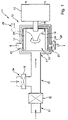
- a pump arrangement 11 is shown in a highly schematic representation.
- This pump arrangement 11 is installed in a water-bearing electrical household appliance according to the invention, in particular in a dishwasher, advantageously under the washing chamber.
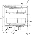
- a dishwasher according to the invention is in 2 shown and more is explained below.
- the pump arrangement 11 has a pump 12 which has a pump housing 13 and a motor 15 .
- a motor axle 16 extends from the motor 15 into the pump housing 13 and carries a conveyor 18 which rotates in a pump chamber 19 inside the pump housing 13.
- the connection between the pump housing 13 and the motor 15 is advantageously fixed, in particular it is a structural unit which, for example, can be releasably screwed or the like. of the motor 15 to the pump housing 13 can be produced. In order to fasten the pump 12 in a dishwasher, it can then be sufficient to provide fastening points on the pump housing 13 alone.
- the conveyor 18 is advantageously of conventional design and corresponds, for example, to a conveyor as can be seen in FIG DE 19903951 A1 is known, to which reference is expressly made in this regard. Furthermore, the dimensions of the pump housing 13 and the other components are not shown to scale here either.
- the pump housing 13 or the pump chamber 19 has a pump access 21 that occurs centrally and axially. Furthermore, a pump outlet 23 is provided, which is arranged laterally or radially. An aforementioned pump drainage 25 with a drainage valve 26 is provided downwards to or advantageously at the lowest point of the pump chamber 19 . Residual water can be removed from the pump housing 19 by opening the drainage valve 26 .
- a heater 28 with heater connections 29 which are led out of the pump housing 13 runs inside the pump chamber 19 .
- the heater 28 shown is, with the exception of a corresponding interruption (not shown) for the pump outlet 23, designed essentially in the manner of a cylinder or encircling the inside close to the inner wall of the pump chamber 19.
- It can be a thin-film or thick-film heater as described above, with heating elements being arranged on at least one of its sides, advantageously on the outside, and possibly also on the other or both sides.
- tubular heaters or the like can also be used. be provided which run closer to the conveyor 18.
- the pump housing 13 can be heated from the outside. However, this can easily be implemented by a person skilled in the art in the different variants.
- a water suction point 31 is provided with a valve 32 for shutting off. This water suction point 31 is connected to a normal drain of a washing chamber of a dishwasher. Furthermore, an air intake point 34 is provided with a corresponding valve 35. Water intake point 31 and air intake point 34 meet in an intersection area 37, which is directly connected to the pump access 21. As explained above, it can be determined by opening and closing the valves 32 and 35 whether either water is sucked in or conveyed at the water suction point 31 or air is sucked in or conveyed at the air suction point 34 and then discharged at the pump outlet 23 .
- the pump outlet 23 can be connected to a single access into a washing chamber of the dishwasher. Then both pumped water and air, in particular also heated, are introduced into the washing chamber in the same way.
- two different delivery points each of which can be opened and closed by valves, can be connected to the pump outlet 23 similar to the pump inlet 21 .
- a dishwasher 40 according to the invention is shown schematically in a lateral section.
- the dishwasher 40 has an inner washing chamber 41 and a door 42 to access it.
- Inside the rinsing chamber 41 there are three rinsing arms 44a-c, which rotate during operation and are supplied via a supply line 45.
- the supply line 45 is connected to the pump outlet 23 and leads to each rinsing arm 44. Valves can possibly also be provided here for selective access to individual rinsing arms 44.
- the water suction point 31 can be switched in a manner not shown with a water outlet from the washing chamber 41 and, advantageously by valves, connected to a fresh water supply.
- the air intake point 34 of the pump arrangement 11 is connected to a fresh air supply, advantageously simply an opening in the dishwasher 40.
- the pump drainage 25 is connected to a conventional waste water line from the dishwasher 40.
- the pump arrangement 11 For the operation of the pump arrangement 11, reference is essentially made to what was mentioned at the outset.
- the valve 35 and the drainage valve 26 are closed, the valve 32 at the water suction point 31 is opened and the pump 12 is operated.
- the engine 15 can be operated at a first rated operating speed, which is the lower of two possible rated operating speeds.
- the water that is pumped and possibly heated by the heater 28 leaves the pump 12 through the pump outlet 23 and is conducted into the interior of the rinsing chamber 41 via the supply line 45 and the rinsing arms 44a-c.
- the motor 15 stops and the valve 32 is closed.
- the pump housing 13 or the pump chamber 19 can run empty by opening the drainage valve 26 .
- the drainage valve 26 is then closed again.
- the valve 35 at the air intake point 34 is then opened and the motor 15 is operated at a second nominal operating speed in order to convey air by means of the conveyor 18 and out of the pump outlet 23 again via the supply line 45 and the flushing arms 44a-c into the interior of the to bring the washing chamber.
- This second rated operating speed can be significantly higher than the aforesaid first rated operating speed, possibly twice to three times as high.
- the introduction of the air which is heated up by the heater 28 for this purpose, is used to dry the dishes towards the end of the washing process.
- the pump assembly 11 then acts like a kind of hair dryer.
- a synchronous motor If a synchronous motor is used as the motor, it can be speed-controlled. Such a synchronous motor then has no fixed nominal operating speed, it can simply be set as desired.
Landscapes
- Engineering & Computer Science (AREA)
- Textile Engineering (AREA)
- Water Supply & Treatment (AREA)
- Structures Of Non-Positive Displacement Pumps (AREA)
- Washing And Drying Of Tableware (AREA)
Priority Applications (1)
| Application Number | Priority Date | Filing Date | Title |
|---|---|---|---|
| PL09778692.5T PL2348944T5 (pl) | 2008-09-25 | 2009-09-24 | Pompa do płynów |
Applications Claiming Priority (2)
| Application Number | Priority Date | Filing Date | Title |
|---|---|---|---|
| DE102008050895A DE102008050895A1 (de) | 2008-09-25 | 2008-09-25 | Pumpe für Fluide |
| PCT/EP2009/006894 WO2010034488A1 (de) | 2008-09-25 | 2009-09-24 | Pumpe für fluide |
Publications (3)
| Publication Number | Publication Date |
|---|---|
| EP2348944A1 EP2348944A1 (de) | 2011-08-03 |
| EP2348944B1 EP2348944B1 (de) | 2017-12-20 |
| EP2348944B2 true EP2348944B2 (de) | 2022-10-26 |
Family
ID=41507949
Family Applications (1)
| Application Number | Title | Priority Date | Filing Date |
|---|---|---|---|
| EP09778692.5A Active EP2348944B2 (de) | 2008-09-25 | 2009-09-24 | Pumpe für fluide |
Country Status (5)
| Country | Link |
|---|---|
| EP (1) | EP2348944B2 (pl) |
| DE (1) | DE102008050895A1 (pl) |
| ES (1) | ES2657433T5 (pl) |
| PL (1) | PL2348944T5 (pl) |
| WO (1) | WO2010034488A1 (pl) |
Families Citing this family (13)
| Publication number | Priority date | Publication date | Assignee | Title |
|---|---|---|---|---|
| DE102008050895A1 (de) | 2008-09-25 | 2010-04-01 | E.G.O. Elektro-Gerätebau GmbH | Pumpe für Fluide |
| DE102010043727A1 (de) | 2010-11-10 | 2012-05-10 | E.G.O. Elektro-Gerätebau GmbH | Pumpe |
| DE102011078017B3 (de) * | 2011-06-22 | 2012-06-21 | E.G.O. Elektro-Gerätebau GmbH | Pumpe |
| DE102012202065B3 (de) | 2012-02-10 | 2013-05-29 | E.G.O. Elektro-Gerätebau GmbH | Pumpe und Verfahren zum Beheizen einer Pumpe |
| US9371841B2 (en) | 2012-03-05 | 2016-06-21 | Electrolux Home Products, Inc. | Safety arrangement for an integrated heater, pump, and motor for an appliance |
| DE102012108449A1 (de) * | 2012-09-11 | 2014-03-13 | Ebm-Papst Mulfingen Gmbh & Co. Kg | Wandring eines Lüfters mit Heizelement |
| DE102012025758B3 (de) | 2012-10-04 | 2021-12-02 | E.G.O. Elektro-Gerätebau GmbH | Impellerpumpe |
| DE102012218145B4 (de) * | 2012-10-04 | 2018-12-27 | E.G.O. Elektro-Gerätebau GmbH | Impellerpumpe |
| DE102013201903A1 (de) | 2013-02-06 | 2014-08-07 | E.G.O. Elektro-Gerätebau GmbH | Wärmepumpenvorrichtung, Verwendung einer Pumpe mit beheizbarer Pumpenkammer in einer Wärmepumpenvorrichtung und Verfahren zum Betrieb einer Wärmepumpenvorrichtung |
| DE102014215853A1 (de) * | 2014-08-11 | 2016-02-11 | BSH Hausgeräte GmbH | Pumpe mit einer Heizvorrichtung, die eine elektrische Folienheizung aufweist |
| DE102019211099A1 (de) | 2019-07-25 | 2021-01-28 | E.G.O. Elektro-Gerätebau GmbH | Wasserführendes Haushaltsgerät und Verfahren zum Betrieb eines wasserführenden Haushaltsgeräts |
| DE102019212952B4 (de) * | 2019-08-28 | 2023-05-11 | Blanco Gmbh + Co Kg | Reinigungsvorrichtung und Verfahren zum Betrieb einer Reinigungsvorrichtung |
| DE102020201179A1 (de) | 2020-01-31 | 2021-08-05 | E.G.O. Elektro-Gerätebau GmbH | Verfahren zum Betrieb eines wasserführenden Haushaltsgeräts und wasserführendes Haushaltsgerät |
Citations (4)
| Publication number | Priority date | Publication date | Assignee | Title |
|---|---|---|---|---|
| DE512274C (de) † | 1928-02-02 | 1930-11-08 | Heinrich Schloemann | Geschirrspuel- und -trockenvorrichtung |
| CH364090A (de) † | 1958-11-21 | 1962-08-31 | Bauknecht Gmbh G | Geschirrspülmaschine |
| CH574732A5 (en) † | 1975-01-31 | 1976-04-30 | Zug Verzinkerei Ag | Dish washing method and machine - drying air is contacted with cold water, fed in by water feed system |
| EP0591774A1 (de) † | 1992-09-23 | 1994-04-13 | Miele & Cie. GmbH & Co. | Geschirrspülmaschine mit einem Durchlauferhitzer |
Family Cites Families (17)
| Publication number | Priority date | Publication date | Assignee | Title |
|---|---|---|---|---|
| DE88019C (pl) * | ||||
| US3568771A (en) * | 1969-04-17 | 1971-03-09 | Borg Warner | Method and apparatus for lifting foaming crude by a variable rpm submersible pump |
| US4858255A (en) * | 1986-05-23 | 1989-08-22 | Premier Pump & Pool Products, Inc. | Hydrotherapy apparatus having preheated air agitation feature |
| DE3705639A1 (de) | 1987-02-21 | 1988-09-01 | Philips Patentverwaltung | Duennschicht-heizelement |
| SG126666A1 (en) * | 1991-12-20 | 2006-11-29 | Fisher & Paykel Appliances Ltd | Dishwasher |
| DE4341215A1 (de) * | 1993-12-03 | 1995-06-08 | Miele & Cie | Kreiselpumpe, insbesondere zur Verwendung als Umwälzpumpe für Geschirrspülmaschinen und Waschmaschinen |
| US5701388A (en) * | 1994-12-22 | 1997-12-23 | Kohler Co. | Combined heater and pump |
| DE19903951B4 (de) | 1999-02-02 | 2013-11-14 | Fritz Eichenauer Gmbh & Co. Kg | Beheizbares Pumpengehäuse zur Flüssigkeitserwärmung |
| DE20107363U1 (de) * | 2001-04-27 | 2001-07-19 | Fritz Eichenauer GmbH & Co. KG, 76870 Kandel | Pumpe mit einem beheizbaren Gehäuse |
| DE102004011365A1 (de) * | 2004-03-05 | 2005-09-22 | Aweco Appliance Systems Gmbh & Co. Kg | Kreiselpumpe |
| ITTO20040592A1 (it) * | 2004-09-08 | 2004-12-08 | Plaset Spa | Chiocciola per una pompa centrifuga |
| DE102004060947A1 (de) | 2004-12-17 | 2006-06-29 | BSH Bosch und Siemens Hausgeräte GmbH | Haushalts-Geschirrspülmaschine und Verfahren zum Betreiben derselben |
| GB2427437B8 (en) | 2005-06-23 | 2011-08-24 | Otter Controls Ltd | Combined heater pump apparatus |
| ITVE20050037U1 (it) * | 2005-11-17 | 2007-05-18 | Irca Spa | Pompa per lavastoviglie provvista di elemento riscaldante.- |
| DE102005062480B4 (de) * | 2005-12-27 | 2014-05-22 | BSH Bosch und Siemens Hausgeräte GmbH | Geschirrspülmaschine |
| DE102007030072A1 (de) | 2007-06-29 | 2009-01-02 | BSH Bosch und Siemens Hausgeräte GmbH | Elektrischen Antriebseinrichtung für ein Wasserführendes Haushaltsgerät |
| DE102008050895A1 (de) | 2008-09-25 | 2010-04-01 | E.G.O. Elektro-Gerätebau GmbH | Pumpe für Fluide |
-
2008
- 2008-09-25 DE DE102008050895A patent/DE102008050895A1/de not_active Ceased
-
2009
- 2009-09-24 WO PCT/EP2009/006894 patent/WO2010034488A1/de not_active Ceased
- 2009-09-24 EP EP09778692.5A patent/EP2348944B2/de active Active
- 2009-09-24 ES ES09778692T patent/ES2657433T5/es active Active
- 2009-09-24 PL PL09778692.5T patent/PL2348944T5/pl unknown
Patent Citations (4)
| Publication number | Priority date | Publication date | Assignee | Title |
|---|---|---|---|---|
| DE512274C (de) † | 1928-02-02 | 1930-11-08 | Heinrich Schloemann | Geschirrspuel- und -trockenvorrichtung |
| CH364090A (de) † | 1958-11-21 | 1962-08-31 | Bauknecht Gmbh G | Geschirrspülmaschine |
| CH574732A5 (en) † | 1975-01-31 | 1976-04-30 | Zug Verzinkerei Ag | Dish washing method and machine - drying air is contacted with cold water, fed in by water feed system |
| EP0591774A1 (de) † | 1992-09-23 | 1994-04-13 | Miele & Cie. GmbH & Co. | Geschirrspülmaschine mit einem Durchlauferhitzer |
Also Published As
| Publication number | Publication date |
|---|---|
| PL2348944T3 (pl) | 2018-07-31 |
| DE102008050895A1 (de) | 2010-04-01 |
| EP2348944B1 (de) | 2017-12-20 |
| PL2348944T5 (pl) | 2023-02-20 |
| EP2348944A1 (de) | 2011-08-03 |
| ES2657433T3 (es) | 2018-03-05 |
| WO2010034488A1 (de) | 2010-04-01 |
| ES2657433T5 (es) | 2023-02-23 |
Similar Documents
| Publication | Publication Date | Title |
|---|---|---|
| EP2348944B1 (de) | Pumpe für fluide | |
| EP1137362B1 (de) | Haushalt-geschirrspülmaschine | |
| EP2384684B1 (de) | Pumpe mit Heizeinrichtung | |
| EP1870508B1 (de) | Pumpe, insbesondere für wasserführende Haushaltsmaschinen | |
| EP2677178B1 (de) | Pumpe | |
| EP2781839B1 (de) | Gargerät mit Reinigungsvorrichtung | |
| EP1230891A1 (de) | Trocknungsgebläse für eine Geschirrspülmaschine | |
| EP1404208A1 (de) | Geschirrspülmaschine mit sprüharmen und mit einer umwälzpumpe | |
| EP3715723A1 (de) | Verteilerscheibe für eine reinigungsflüssigkeit, verteilersystem, gargerät mit einem garraum und verfahren zu dessen reinigung | |
| EP3455502A1 (de) | Flüssigkeitsheizpumpe zum fördern und aufheizen von flüssigkeit in einem wasserführenden haushaltsgerät | |
| EP2055958B1 (de) | Wasserführendes Haushaltsgerät mit einer Pumpe mit Ventilfunktion | |
| DE102009002224B4 (de) | Wasserführendes Haushaltsgerät, insbesondere Geschirrspülmaschine | |
| EP2420609B1 (de) | Laugenpumpe für wasserführende Haushaltgeräte und wasserführendes Haushaltgerät | |
| EP3733040A1 (de) | Wasserführendes haushaltsgerät | |
| EP2862494A1 (de) | Wasserführendes Haushaltsgerät | |
| EP1010384A1 (de) | Gargerät und Verfahren zur Wärmebehandlung eines Gargutes mit Dampf | |
| EP1091183B1 (de) | Vorrichtung zum Trocknen und Reinigen von kleinstückigem Gut, insbesondere von zerkleinerten Kunststoffabfällen | |
| DE102010042513A1 (de) | Pumpe für ein Hausgerät, Hausgerät mit einer Pumpe und Verfahren zum Betreiben eines Hausgeräts | |
| EP3868947B1 (de) | Verfahren zum betrieb eines wasserführenden haushaltsgeräts und wasserführendes hauhaltsgerät | |
| EP1402780A2 (de) | Backofen | |
| EP0366683B1 (de) | Backofen | |
| DE19535600A1 (de) | Geruchs-Absaugung aus WC-Becken mittels Radialgebläse mit kommutatorlosem Motor | |
| DE102019109633A1 (de) | Gebläse, insbesondere für ein elektrisches Gerät, sowie elektrisches Gerät | |
| EP3396076A1 (de) | Duschkreislaufsystem | |
| EP3545812B1 (de) | Geschirrspülmaschine, insbesondere haushaltsgeschirrspülmaschine |
Legal Events
| Date | Code | Title | Description |
|---|---|---|---|
| PUAI | Public reference made under article 153(3) epc to a published international application that has entered the european phase |
Free format text: ORIGINAL CODE: 0009012 |
|
| 17P | Request for examination filed |
Effective date: 20110413 |
|
| AK | Designated contracting states |
Kind code of ref document: A1 Designated state(s): AT BE BG CH CY CZ DE DK EE ES FI FR GB GR HR HU IE IS IT LI LT LU LV MC MK MT NL NO PL PT RO SE SI SK SM TR |
|
| DAX | Request for extension of the european patent (deleted) | ||
| 17Q | First examination report despatched |
Effective date: 20140611 |
|
| STAA | Information on the status of an ep patent application or granted ep patent |
Free format text: STATUS: EXAMINATION IS IN PROGRESS |
|
| GRAP | Despatch of communication of intention to grant a patent |
Free format text: ORIGINAL CODE: EPIDOSNIGR1 |
|
| STAA | Information on the status of an ep patent application or granted ep patent |
Free format text: STATUS: GRANT OF PATENT IS INTENDED |
|
| INTG | Intention to grant announced |
Effective date: 20170717 |
|
| GRAS | Grant fee paid |
Free format text: ORIGINAL CODE: EPIDOSNIGR3 |
|
| GRAA | (expected) grant |
Free format text: ORIGINAL CODE: 0009210 |
|
| STAA | Information on the status of an ep patent application or granted ep patent |
Free format text: STATUS: THE PATENT HAS BEEN GRANTED |
|
| AK | Designated contracting states |
Kind code of ref document: B1 Designated state(s): AT BE BG CH CY CZ DE DK EE ES FI FR GB GR HR HU IE IS IT LI LT LU LV MC MK MT NL NO PL PT RO SE SI SK SM TR |
|
| REG | Reference to a national code |
Ref country code: GB Ref legal event code: FG4D Free format text: NOT ENGLISH |
|
| REG | Reference to a national code |
Ref country code: CH Ref legal event code: EP |
|
| REG | Reference to a national code |
Ref country code: IE Ref legal event code: FG4D Free format text: LANGUAGE OF EP DOCUMENT: GERMAN |
|
| REG | Reference to a national code |
Ref country code: AT Ref legal event code: REF Ref document number: 955592 Country of ref document: AT Kind code of ref document: T Effective date: 20180115 |
|
| REG | Reference to a national code |
Ref country code: DE Ref legal event code: R096 Ref document number: 502009014616 Country of ref document: DE |
|
| REG | Reference to a national code |
Ref country code: ES Ref legal event code: FG2A Ref document number: 2657433 Country of ref document: ES Kind code of ref document: T3 Effective date: 20180305 |
|
| REG | Reference to a national code |
Ref country code: NL Ref legal event code: MP Effective date: 20171220 |
|
| PG25 | Lapsed in a contracting state [announced via postgrant information from national office to epo] |
Ref country code: NO Free format text: LAPSE BECAUSE OF FAILURE TO SUBMIT A TRANSLATION OF THE DESCRIPTION OR TO PAY THE FEE WITHIN THE PRESCRIBED TIME-LIMIT Effective date: 20180320 Ref country code: LT Free format text: LAPSE BECAUSE OF FAILURE TO SUBMIT A TRANSLATION OF THE DESCRIPTION OR TO PAY THE FEE WITHIN THE PRESCRIBED TIME-LIMIT Effective date: 20171220 Ref country code: FI Free format text: LAPSE BECAUSE OF FAILURE TO SUBMIT A TRANSLATION OF THE DESCRIPTION OR TO PAY THE FEE WITHIN THE PRESCRIBED TIME-LIMIT Effective date: 20171220 Ref country code: SE Free format text: LAPSE BECAUSE OF FAILURE TO SUBMIT A TRANSLATION OF THE DESCRIPTION OR TO PAY THE FEE WITHIN THE PRESCRIBED TIME-LIMIT Effective date: 20171220 |
|
| REG | Reference to a national code |
Ref country code: LT Ref legal event code: MG4D |
|
| PG25 | Lapsed in a contracting state [announced via postgrant information from national office to epo] |
Ref country code: HR Free format text: LAPSE BECAUSE OF FAILURE TO SUBMIT A TRANSLATION OF THE DESCRIPTION OR TO PAY THE FEE WITHIN THE PRESCRIBED TIME-LIMIT Effective date: 20171220 Ref country code: BG Free format text: LAPSE BECAUSE OF FAILURE TO SUBMIT A TRANSLATION OF THE DESCRIPTION OR TO PAY THE FEE WITHIN THE PRESCRIBED TIME-LIMIT Effective date: 20180320 Ref country code: GR Free format text: LAPSE BECAUSE OF FAILURE TO SUBMIT A TRANSLATION OF THE DESCRIPTION OR TO PAY THE FEE WITHIN THE PRESCRIBED TIME-LIMIT Effective date: 20180321 Ref country code: LV Free format text: LAPSE BECAUSE OF FAILURE TO SUBMIT A TRANSLATION OF THE DESCRIPTION OR TO PAY THE FEE WITHIN THE PRESCRIBED TIME-LIMIT Effective date: 20171220 |
|
| PG25 | Lapsed in a contracting state [announced via postgrant information from national office to epo] |
Ref country code: NL Free format text: LAPSE BECAUSE OF FAILURE TO SUBMIT A TRANSLATION OF THE DESCRIPTION OR TO PAY THE FEE WITHIN THE PRESCRIBED TIME-LIMIT Effective date: 20171220 |
|
| PG25 | Lapsed in a contracting state [announced via postgrant information from national office to epo] |
Ref country code: SK Free format text: LAPSE BECAUSE OF FAILURE TO SUBMIT A TRANSLATION OF THE DESCRIPTION OR TO PAY THE FEE WITHIN THE PRESCRIBED TIME-LIMIT Effective date: 20171220 Ref country code: CZ Free format text: LAPSE BECAUSE OF FAILURE TO SUBMIT A TRANSLATION OF THE DESCRIPTION OR TO PAY THE FEE WITHIN THE PRESCRIBED TIME-LIMIT Effective date: 20171220 Ref country code: EE Free format text: LAPSE BECAUSE OF FAILURE TO SUBMIT A TRANSLATION OF THE DESCRIPTION OR TO PAY THE FEE WITHIN THE PRESCRIBED TIME-LIMIT Effective date: 20171220 Ref country code: CY Free format text: LAPSE BECAUSE OF FAILURE TO SUBMIT A TRANSLATION OF THE DESCRIPTION OR TO PAY THE FEE WITHIN THE PRESCRIBED TIME-LIMIT Effective date: 20171220 |
|
| PG25 | Lapsed in a contracting state [announced via postgrant information from national office to epo] |
Ref country code: IS Free format text: LAPSE BECAUSE OF FAILURE TO SUBMIT A TRANSLATION OF THE DESCRIPTION OR TO PAY THE FEE WITHIN THE PRESCRIBED TIME-LIMIT Effective date: 20180420 Ref country code: RO Free format text: LAPSE BECAUSE OF FAILURE TO SUBMIT A TRANSLATION OF THE DESCRIPTION OR TO PAY THE FEE WITHIN THE PRESCRIBED TIME-LIMIT Effective date: 20171220 Ref country code: SM Free format text: LAPSE BECAUSE OF FAILURE TO SUBMIT A TRANSLATION OF THE DESCRIPTION OR TO PAY THE FEE WITHIN THE PRESCRIBED TIME-LIMIT Effective date: 20171220 |
|
| REG | Reference to a national code |
Ref country code: DE Ref legal event code: R026 Ref document number: 502009014616 Country of ref document: DE |
|
| PLBI | Opposition filed |
Free format text: ORIGINAL CODE: 0009260 |
|
| PG25 | Lapsed in a contracting state [announced via postgrant information from national office to epo] |
Ref country code: MT Free format text: LAPSE BECAUSE OF FAILURE TO SUBMIT A TRANSLATION OF THE DESCRIPTION OR TO PAY THE FEE WITHIN THE PRESCRIBED TIME-LIMIT Effective date: 20171220 |
|
| PLAX | Notice of opposition and request to file observation + time limit sent |
Free format text: ORIGINAL CODE: EPIDOSNOBS2 |
|
| 26 | Opposition filed |
Opponent name: BLECKMANN GMBH & CO. KG Effective date: 20180920 |
|
| PG25 | Lapsed in a contracting state [announced via postgrant information from national office to epo] |
Ref country code: DK Free format text: LAPSE BECAUSE OF FAILURE TO SUBMIT A TRANSLATION OF THE DESCRIPTION OR TO PAY THE FEE WITHIN THE PRESCRIBED TIME-LIMIT Effective date: 20171220 |
|
| PLBB | Reply of patent proprietor to notice(s) of opposition received |
Free format text: ORIGINAL CODE: EPIDOSNOBS3 |
|
| PG25 | Lapsed in a contracting state [announced via postgrant information from national office to epo] |
Ref country code: SI Free format text: LAPSE BECAUSE OF FAILURE TO SUBMIT A TRANSLATION OF THE DESCRIPTION OR TO PAY THE FEE WITHIN THE PRESCRIBED TIME-LIMIT Effective date: 20171220 |
|
| PG25 | Lapsed in a contracting state [announced via postgrant information from national office to epo] |
Ref country code: MC Free format text: LAPSE BECAUSE OF FAILURE TO SUBMIT A TRANSLATION OF THE DESCRIPTION OR TO PAY THE FEE WITHIN THE PRESCRIBED TIME-LIMIT Effective date: 20171220 |
|
| REG | Reference to a national code |
Ref country code: CH Ref legal event code: PL |
|
| GBPC | Gb: european patent ceased through non-payment of renewal fee |
Effective date: 20180924 |
|
| REG | Reference to a national code |
Ref country code: BE Ref legal event code: MM Effective date: 20180930 |
|
| REG | Reference to a national code |
Ref country code: IE Ref legal event code: MM4A |
|
| PG25 | Lapsed in a contracting state [announced via postgrant information from national office to epo] |
Ref country code: LU Free format text: LAPSE BECAUSE OF NON-PAYMENT OF DUE FEES Effective date: 20180924 |
|
| PG25 | Lapsed in a contracting state [announced via postgrant information from national office to epo] |
Ref country code: IE Free format text: LAPSE BECAUSE OF NON-PAYMENT OF DUE FEES Effective date: 20180924 |
|
| PG25 | Lapsed in a contracting state [announced via postgrant information from national office to epo] |
Ref country code: BE Free format text: LAPSE BECAUSE OF NON-PAYMENT OF DUE FEES Effective date: 20180930 Ref country code: FR Free format text: LAPSE BECAUSE OF NON-PAYMENT OF DUE FEES Effective date: 20180930 Ref country code: CH Free format text: LAPSE BECAUSE OF NON-PAYMENT OF DUE FEES Effective date: 20180930 Ref country code: LI Free format text: LAPSE BECAUSE OF NON-PAYMENT OF DUE FEES Effective date: 20180930 |
|
| PG25 | Lapsed in a contracting state [announced via postgrant information from national office to epo] |
Ref country code: GB Free format text: LAPSE BECAUSE OF NON-PAYMENT OF DUE FEES Effective date: 20180924 |
|
| REG | Reference to a national code |
Ref country code: AT Ref legal event code: MM01 Ref document number: 955592 Country of ref document: AT Kind code of ref document: T Effective date: 20180924 |
|
| PG25 | Lapsed in a contracting state [announced via postgrant information from national office to epo] |
Ref country code: AT Free format text: LAPSE BECAUSE OF NON-PAYMENT OF DUE FEES Effective date: 20180924 |
|
| PG25 | Lapsed in a contracting state [announced via postgrant information from national office to epo] |
Ref country code: PT Free format text: LAPSE BECAUSE OF FAILURE TO SUBMIT A TRANSLATION OF THE DESCRIPTION OR TO PAY THE FEE WITHIN THE PRESCRIBED TIME-LIMIT Effective date: 20171220 Ref country code: HU Free format text: LAPSE BECAUSE OF FAILURE TO SUBMIT A TRANSLATION OF THE DESCRIPTION OR TO PAY THE FEE WITHIN THE PRESCRIBED TIME-LIMIT; INVALID AB INITIO Effective date: 20090924 |
|
| PG25 | Lapsed in a contracting state [announced via postgrant information from national office to epo] |
Ref country code: MK Free format text: LAPSE BECAUSE OF NON-PAYMENT OF DUE FEES Effective date: 20171220 |
|
| APBM | Appeal reference recorded |
Free format text: ORIGINAL CODE: EPIDOSNREFNO |
|
| APBP | Date of receipt of notice of appeal recorded |
Free format text: ORIGINAL CODE: EPIDOSNNOA2O |
|
| APAH | Appeal reference modified |
Free format text: ORIGINAL CODE: EPIDOSCREFNO |
|
| APBM | Appeal reference recorded |
Free format text: ORIGINAL CODE: EPIDOSNREFNO |
|
| APBP | Date of receipt of notice of appeal recorded |
Free format text: ORIGINAL CODE: EPIDOSNNOA2O |
|
| APBQ | Date of receipt of statement of grounds of appeal recorded |
Free format text: ORIGINAL CODE: EPIDOSNNOA3O |
|
| APBU | Appeal procedure closed |
Free format text: ORIGINAL CODE: EPIDOSNNOA9O |
|
| PUAH | Patent maintained in amended form |
Free format text: ORIGINAL CODE: 0009272 |
|
| STAA | Information on the status of an ep patent application or granted ep patent |
Free format text: STATUS: PATENT MAINTAINED AS AMENDED |
|
| 27A | Patent maintained in amended form |
Effective date: 20221026 |
|
| AK | Designated contracting states |
Kind code of ref document: B2 Designated state(s): AT BE BG CH CY CZ DE DK EE ES FI FR GB GR HR HU IE IS IT LI LT LU LV MC MK MT NL NO PL PT RO SE SI SK SM TR |
|
| REG | Reference to a national code |
Ref country code: DE Ref legal event code: R102 Ref document number: 502009014616 Country of ref document: DE |
|
| REG | Reference to a national code |
Ref country code: ES Ref legal event code: DC2A Ref document number: 2657433 Country of ref document: ES Kind code of ref document: T5 Effective date: 20230223 |
|
| PGFP | Annual fee paid to national office [announced via postgrant information from national office to epo] |
Ref country code: PL Payment date: 20240819 Year of fee payment: 16 |
|
| PGFP | Annual fee paid to national office [announced via postgrant information from national office to epo] |
Ref country code: TR Payment date: 20240917 Year of fee payment: 16 |
|
| PGFP | Annual fee paid to national office [announced via postgrant information from national office to epo] |
Ref country code: IT Payment date: 20240930 Year of fee payment: 16 Ref country code: ES Payment date: 20241018 Year of fee payment: 16 |
|
| PGFP | Annual fee paid to national office [announced via postgrant information from national office to epo] |
Ref country code: DE Payment date: 20250919 Year of fee payment: 17 |