EP2348591A2 - Tragarm - Google Patents
Tragarm Download PDFInfo
- Publication number
- EP2348591A2 EP2348591A2 EP11152264A EP11152264A EP2348591A2 EP 2348591 A2 EP2348591 A2 EP 2348591A2 EP 11152264 A EP11152264 A EP 11152264A EP 11152264 A EP11152264 A EP 11152264A EP 2348591 A2 EP2348591 A2 EP 2348591A2
- Authority
- EP
- European Patent Office
- Prior art keywords
- profile
- connector
- support
- arm according
- support profile
- Prior art date
- Legal status (The legal status is an assumption and is not a legal conclusion. Google has not performed a legal analysis and makes no representation as to the accuracy of the status listed.)
- Granted
Links
Images




Classifications
-
- H—ELECTRICITY
- H02—GENERATION; CONVERSION OR DISTRIBUTION OF ELECTRIC POWER
- H02G—INSTALLATION OF ELECTRIC CABLES OR LINES, OR OF COMBINED OPTICAL AND ELECTRIC CABLES OR LINES
- H02G3/00—Installations of electric cables or lines or protective tubing therefor in or on buildings, equivalent structures or vehicles
- H02G3/02—Details
- H02G3/04—Protective tubing or conduits, e.g. cable ladders or cable troughs
- H02G3/0406—Details thereof
- H02G3/0418—Covers or lids; Their fastenings
-
- H—ELECTRICITY
- H02—GENERATION; CONVERSION OR DISTRIBUTION OF ELECTRIC POWER
- H02G—INSTALLATION OF ELECTRIC CABLES OR LINES, OR OF COMBINED OPTICAL AND ELECTRIC CABLES OR LINES
- H02G3/00—Installations of electric cables or lines or protective tubing therefor in or on buildings, equivalent structures or vehicles
- H02G3/02—Details
- H02G3/04—Protective tubing or conduits, e.g. cable ladders or cable troughs
- H02G3/0437—Channels
-
- F—MECHANICAL ENGINEERING; LIGHTING; HEATING; WEAPONS; BLASTING
- F16—ENGINEERING ELEMENTS AND UNITS; GENERAL MEASURES FOR PRODUCING AND MAINTAINING EFFECTIVE FUNCTIONING OF MACHINES OR INSTALLATIONS; THERMAL INSULATION IN GENERAL
- F16M—FRAMES, CASINGS OR BEDS OF ENGINES, MACHINES OR APPARATUS, NOT SPECIFIC TO ENGINES, MACHINES OR APPARATUS PROVIDED FOR ELSEWHERE; STANDS; SUPPORTS
- F16M2200/00—Details of stands or supports
- F16M2200/06—Arms
- F16M2200/065—Arms with a special structure, e.g. reinforced or adapted for space reduction
Definitions
- the invention relates to a support arm for a Tragarmsystem with a support profile which surrounds a receiving space partially, the receiving space is in communication with the environment via an insertion opening, wherein the insertion is limited at least partially mutually opposite lugs of the support profile.
- Support arms are used as parts of support arm systems. They serve, for example, to hang a machine control unit on a machine tool and make it accessible to a user.
- the machine control unit is usually connected by means of electrical signal lines with the machine control.
- the signal lines are housed protected in the receiving space of the supporting profile.
- the support arm has a support profile which is designed as an aluminum bar press profile.
- the support profile has wall elements which form the receiving space for the signal lines limit.
- the cables can be introduced via an insertion opening into the receiving space.
- a lid member is used, which closes the insertion opening. Since the support profiles are sometimes exposed to very high stresses, high demands are placed on the profile stiffness. Accordingly, in the region of the inner cross section of the support profile, a horizontal crosspiece is arranged, which is integrally formed on vertical side walls of the support profile.
- the projections of the support profile, which limit the insertion are connected to each other by means of a connector, and that the connector has two mutually bracing fasteners.
- the connector thus closes the open side of the support profile, resulting in a quasi-closed hollow profile.
- the connector does not have to extend over the entire Achsialerstreckung the support profile, but it is sufficient if this is also attached only to highly stressed areas.
- the bracing fasteners are used to bind the two approaches firmly together.
- the connector provides extended functionality when it serves as a mounting point for additional attachments that are to be attached to the support profile. For example, it is conceivable that small housing, cable holder, adjusting elements, etc. are coupled to the connector. Also, it is possible to carry other media (e.g., gases or liquids) that must be carried separately from electrical signal lines.
- media e.g., gases or liquids
- the connector is also clearly aligned with respect to the support profile.
- a conceivable alternative of the invention is characterized in that at least one of the fastening parts has pointed elevations which dig into the material of the supporting profile. In this way, a positive connection between the connector and the support profile is achieved, which further increases the strength.
- a cover is detachably fastened, which covers the insertion and / or the connector at least partially, then a visually appealing conclusion can be achieved in a simple manner.
- the cover may have a veneer on which the two approaches are integrally formed.
- the approaches have latching elements which are latched with counter-locking elements of the support profile.
- the cover can be mounted easily and quickly.
- a particularly rigid design of the support profile, in particular against bending and torsional stresses simultaneously is extremely resistant, results from the fact that the support section is divided by integrally formed boundary elements in two or more chambers, the boundary elements run web-like in profile longitudinal direction, that the limiting elements are integrally connected to the outer periphery limiting wall portions of the support profile and at its other end a connecting element are connected, which is arranged within the space enclosed by the support profile.
- the limiting elements can in particular be V-shaped at an angle to each other, whereby transverse forces acting from different directions can be reliably removed.
- a further preferred variant of the invention is such that at least two limiting elements delimit the receiving space. This results in a simple profile structure.
- a further stiffening of the support profile is achieved in that on both sides of the connecting element in each case two limiting elements are arranged, which extend in pairs in each case in the direction of the profile upper or -unterseite.
- the support section 10 has two mutually parallel vertical side walls 11, which terminate at their longitudinal ends with corner pieces 13.
- the two lower corner pieces 13 are integrally connected to each other by means of a transition piece 12.
- the two upper corner pieces 13 each carry a lug 17, which is web-like and limits an insertion opening in the profile longitudinal direction.
- two recesses 17.1 and 17.2 are incorporated in the form of grooves. These recesses 17.1 and 17.2 extend in the profile longitudinal direction.
- the projection 17 also carries an upwardly projecting counter-latching element, to the end a latching projection 16.1 is formed.
- the counter-latching element 16, together with a wall of the corner piece 13, defines a groove 15.
- the two projections 17 delimit an insertion opening through which a receiving space A is accessible.
- the receiving space A is surrounded by areas of the two upper corner pieces 13, the lugs 17 and limiting webs 18.1.
- the boundary webs 18.1 each end in one piece to the upper corner pieces 13 and extend at an angle inwardly toward the profile center.
- the boundary webs 18.1 are integrally formed on their, the corner pieces 13 facing away from the end of a connecting element 18.2. Facing away from the receiving space A, the connecting element 18.2 carries two further connecting webs 18.3. These are in turn integrally formed on the two lower corner pieces 13 and also extend at an angle.
- the corner pieces 13 are each equipped with two integrally molded screw 19, which extend continuously in the profile longitudinal direction. At this screw 19 can not be screwed by means of connecting screws support arm components are shown. For example, as Tragarmkomponenten corner pieces, adapters, swivel joints, etc. are grown.
- the two lugs 17 define an insertion opening which provides access to the receiving space A.
- This insertion opening can be covered by means of a cover 20.
- the cover 20 is formed as a plastic molded part and has a convex facing 21, are integrally formed on the two downwardly projecting lugs 22.
- the lugs 22 are parallel to each other and at a distance.
- the free ends of the lugs 22 close with latching elements 23.
- the locking elements 23 are deflected on the counter-locking elements 16 to the outside until they snap behind the locking projection 16.1.
- the convex veneer 21 then merges into the subsequent surfaces of the corner pieces 13 to provide a harmonic termination corresponding to the termination formed on the opposite side to the transition piece 12.
- FIG. 6 shows the mounted cover.
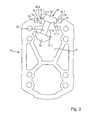
- FIG. 3 a connector 30 is shown.
- This connector consists of two fastening parts 31 and 32, which are designed substantially identical.
- the fastening parts 31, 32 each have a base part 31.3, 32.3, on the side projections 31.1, 32.1 are formed.
- the projections 31.1, 32.1 are formed as ribs with a convexly curved surface.
- recesses 31.2, 32.2 Inward close to the Projections 31.1, 32.1 recesses 31.2, 32.2, which extend in the form of grooves in the longitudinal direction of the connector 30. Between the recesses 31.1 and 32.1 remains a transition section. In this transition portion of the fixing part 31 threaded seats 31.4 are incorporated.
- the threaded receivers 31.4 are opposite drilled screw 32.4 and bores 32.5 drilled.
- the threaded holes 31.4 are opposite holes 32.5.
- clamping screws 33 can be passed and screwed into the threaded holes 31.4.
- Through the holes 32.5 through screws for attachment of attachments 40, 50 can be screwed into the threaded holes 31.4.
- elevations 32.6 which are formed in the form of serrations on the projections 31.1 and 32.1, move towards one another.
- the connector 30 may be attached to the support profile 10.
- the connector 30 is inserted into the insertion opening, as the FIG. 3 illustrated.
- the connector 30 can be inserted either over the open longitudinal side of the support profile 10 or, as in FIG. 3 is illustrated, this is pivoted from above into the insertion opening.
- the fastening part 32 rests on the outside on the lugs 17.
- the fastening part 31 is arranged in the region of the receiving space A below the lugs 17. Now, when the clamping screws 33 are tightened, so move the mounting members 31, 32 toward each other.
- the projections 32.1, 31.1 dive into the groove-shaped recesses 17.1, 17.2 of the lugs 17.
- the connector 30 with a corresponding cover 20, as with reference to the FIG. 1 already explained.
- the connector 30 is thus optically invisible.
- the connector 30 may extend over the entire length of the support profile 10 or only over a limited portion of the support profile.
- attachments 40, 50 can be attached to the connector 30.
- a small housing as an attachment 40.
- the small housing has a housing lower part 42 which can be closed by a cover 41.
- the lid 41 is connected to the lower housing part via screws 43. With the cover removed 41 fixing screws can be passed through the housing bottom of the housing base and screwed into the mounting receptacles 31.4 of the connector 30. In this way, the attachment 40 can connect to the support section 10.
- FIG. 7 a further embodiment of an attachment 50 is shown.
- two clamps / retaining clips 52 are screwed to two connectors 30 arranged at the longitudinal ends of the support profile.
- the clamps / retaining clips 52 are again fixed in the fastening receptacles 31.4 of the connector 30.
- the clamps / brackets 52 are used to attach protective or media hoses or the direct attachment of cables.
Landscapes
- Engineering & Computer Science (AREA)
- Architecture (AREA)
- Civil Engineering (AREA)
- Structural Engineering (AREA)
- Mutual Connection Of Rods And Tubes (AREA)
- Connector Housings Or Holding Contact Members (AREA)
- Clamps And Clips (AREA)
- Details Of Connecting Devices For Male And Female Coupling (AREA)
Abstract
Description
- Die Erfindung betrifft einen Tragarm für ein Tragarmsystem mit einem Tragprofil, das einen Aufnahmeraum teilweise umgibt, wobei der Aufnahmeraum mit der Umgebung über eine Einführöffnung in räumlicher Verbindung steht, wobei die Einführöffnung zumindest bereichsweise voneinander gegenüberliegenden Ansätzen des Tragprofiles begrenzt ist.
- Tragarme werden als Teile von Tragarmsystemen eingesetzt. Sie dienen beispielsweise dazu, ein Maschinensteuergerät an einer Werkzeugmaschine aufzuhängen und einem Benutzer zugänglich zu machen. Das Maschinensteuergerät steht üblicherweise mittels elektrischer Signalleitungen mit der Maschinensteuerung in Verbindung. Die Signalleitungen sind in dem Aufnahmeraum des Tragprofiles geschützt untergebracht.
- Aus der
DE 38 05 425 A1 ist ein Tragarm für ein Tragarmsystem bekannt. Der Tragarm weist ein Tragprofil auf, das als Aluminium-Stangenpressprofil ausgebildet ist. Das Tragprofil weist Wandungselemente auf, die den Aufnahmeraum für die Signalleitungen begrenzen. Die Kabel können über eine Einführöffnung in den Aufnahmeraum eingebracht werden. Zur geschützten Abdeckung wird ein Deckelelement verwendet, das die Einführöffnung verschließt. Da die Tragprofile teilweise sehr hohen Beanspruchungen ausgesetzt sind, werden hohe Anforderungen an die Profilsteifigkeit gestellt. Dementsprechend ist in dem Bereich des Innenquerschnitts des Tragprofils ein horizontaler Quersteg angeordnet, der einteilig an vertikale Seitenwandungen des Tragprofils angeformt ist. - Bei sehr hohen Beanspruchungen bieten allseitig geschlossene Tragprofile gute Belastbarkeiten. Diese allseitig geschlossenen Tragprofile weisen ebenfalls einen Aufnahmeraum für Kabel auf, die allerdings durch die offenen Stirnseiten der Tragprofile eingeschoben werden müssen. Die nachträgliche Installation ergänzender Leitungen ist mit einem gewissen Montageaufwand verbunden. Ein solches Tragprofil ist beispielsweise in der P 44 03 593.4-09 bekannt.
- Es ist Aufgabe der Erfindung, ein Tragarm für ein Tragarmsystem bereitzustellen, bei dem das Tragprofil eine hohe Profilsteifigkeit aufweist und bei dem jedoch gleichzeitig die Kabelinstallation einfach durchführbar ist.
- Diese Aufgabe wird mit den Merkmalen des Anspruches 1 gelöst. Demgemäß ist es vorgesehen, dass die Ansätze des Tragprofils, die die Einführöffnung begrenzen, mittels eines Verbinders miteinander verbunden sind, und dass der Verbinder zwei gegeneinander verspannbare Befestigungsteile aufweist. Der Verbinder schließt somit die offene Seite des Tragprofils, wodurch sich ein quasi geschlossenes Hohlprofil ergibt. Dabei muss der Verbinder nicht über die gesamte Achsialerstreckung des Tragprofils reichen, sondern es reicht aus, wenn dieser auch nur an hoch beanspruchten Stellen befestigt ist. Die verspannbaren Befestigungsteile dienen dazu, die beiden Ansätze fest aneinander zu binden.
- Eine erweiterte Funktionalität bietet der Verbinder dann, wenn er als Befestigungsstelle für zusätzliche Anbauten dient, die am Tragprofil befestigt werden sollen. Beispielsweise ist es denkbar, dass Kleingehäuse, Kabelhalter, Stellelemente, etc. an den Verbinder angekoppelt sind. Auch ist das Führen anderer Medien (z.B. Gase oder Flüssigkeiten), die getrennt von elektrischen Signalleitungen geführt werden müssen, dort möglich.
- Gemäß einer bevorzugten Erfindungsvariante kann es vorgesehen sein, dass die Ansätze und die Befestigungsteile über Spannabschnitte miteinander in Wirkverbindung treten, wobei die Spannabschnitte eine Kraft in die Ansätze einbringen, die in Richtung auf den jeweils gegenüberliegenden Ansatz orientiert ist. Auf diese Weise wird eine spielfreie Verspannung des Verbinders mit den Ansätzen garantiert, wodurch sich ein definierter und fester Spannverband ergibt. Insbesondere ist dabei auch der Verbinder eindeutig gegenüber dem Tragprofil ausgerichtet.
- Eine denkbare Erfindungsalternative ist dadurch gekennzeichnet, dass wenigstens eines der Befestigungsteile spitzenförmige Erhebungen aufweist, die sich in das Material des Tragprofils eingraben. Auf diese Weise wird ein Formschluss zwischen dem Verbinder und dem Tragprofil erreicht, der die Festigkeit weiter erhöht.
- Wenn vorgesehen ist, dass an dem Tragprofil und/oder dem Verbinder eine Abdeckung lösbar befestigbar ist, die die Einführöffnung und/oder den Verbinder zumindest bereichsweise überdeckt, dann kann auf einfache Weise ein optisch ansprechender Abschluss erreicht werden.
- Die Abdeckung kann dabei eine Verblendung aufweisen, an der die zwei Ansätze einteilig angeformt sind. Die Ansätze weisen dabei Rastelemente auf, die mit Gegenrastelementen des Tragprofils verrastet sind. Auf diese Weise lässt sich die Abdeckung einfach und schnell montieren. Eine besonders steife Ausgestaltung des Tragprofils, die insbesondere gegen Biege- und gleichzeitig Torsionsbeanspruchungen äußerst widerstandsfähig ist, ergibt sich dadurch, dass das Tragprofil mittels angeformter Begrenzungselemente in zwei oder mehrere Kammern unterteilt ist, wobei die Begrenzungselemente stegartig in Profillängsrichtung verlaufen, dass die Begrenzungselemente einstückig an den den Außenumfang begrenzenden Wandungsbereichen des Tragprofils angeschlossen sind und an ihrem anderen Endbereich an ein Verbindungselement angeschlossen sind, das innerhalb des von dem Tragprofil umschlossenen Raumes angeordnet ist.
- Dabei können die Begrenzungselemente insbesondere V-förmig zueinander im Winkel stehen, wodurch aus unterschiedlicher Richtung wirkende Querkräfte zuverlässig abgetragen werden können.
- Eine weitere bevorzugte Erfindungsvariante ist derart, dass wenigstens zwei Begrenzungselemente den Aufnahmeraum begrenzen. Hierdurch ergibt sich ein einfacher Profilaufbau.
- Eine weitere Aussteifung des Tragprofils wird dadurch erreicht, dass beiderseits des Verbindungselementes jeweils zwei Begrenzungselemente angeordnet sind, die sich paarweise jeweils in Richtung zur Profilober- bzw. -unterseite hin erstrecken.
- Die Erfindung wird im Folgenden anhand eines in den Zeichnungen dargestellten Ausführungsbeispieles näher erläutert. Es zeigen:
- Figur 1
- in Stirnansicht ein Tragprofil eines Tragarmes mit einer Abdeckung;
- Figur 2
- einen Verbinder zur Ankopplung an das Tragprofil gemäß
Figur 1 in perspektivischer Darstellung; - Figur 3
- das Tragprofil gemäß
Figur 1 mit eingesetztem Verbinder; - Figur 4
- die Darstellung gemäß
Figur 3 jedoch mit fertig montiertem Verbinder; - Figur 5
- eine perspektivische Darstellung des Tragprofils mit Verbinder und Abdeckung;
- Figur 6
- das Tragprofil gemäß
Figur 5 mit einem angebauten Kleingehäuse; und - Figur 7
- ein Tragprofil mit einer angebauten Stellspindel.
- Wie die
Figur 1 veranschaulicht, weist das Tragprofil 10 zwei zueinander parallele vertikale Seitenwände 11 auf, die an ihren längsseitigen Enden mit Eckstücken 13 abschließen. Die beiden unteren Eckstücke 13 sind mittels eines Übergangsstückes 12 einteilig miteinander verbunden. Die beiden oberen Eckstücke 13 tragen jeweils einen Ansatz 17, der stegartig ausgebildet ist und in Profillängsrichtung eine Einführöffnung begrenzt. In die beiden Ansätze 17 sind zwei Vertiefungen 17.1 und 17.2 in Form von Nuten eingearbeitet. Diese Vertiefungen 17.1 und 17.2 erstrecken sich in Profillängsrichtung. Der Ansatz 17 trägt weiterhin ein nach oben abstehendes Gegenrastelement, an das endseitig ein Rastvorsprung 16.1 angeformt ist. Das Gegenrastelement 16 begrenzt zusammen mit einer Wandung des Eckstücks 13 eine Nut 15. Wie vorstehend bereits erwähnt, begrenzen die beiden Ansätze 17 eine Einführöffnung, durch die hindurch ein Aufnahmeraum A zugänglich ist. Der Aufnahmeraum A wird dabei von Bereichen der beiden oberen Eckstücke 13, der Ansätze 17 und von Begrenzungsstegen 18.1 umgeben. Die Begrenzungsstege 18.1 schließen jeweils endseitig einteilig an die oberen Eckstücke 13 an und erstrecken sich im Winkel einwärts gerichtet zur Profilmitte hin. Die Begrenzungsstege 18.1 sind an ihrem, den Eckstücken 13 abgewandten Ende an ein Verbindungselement 18.2 angeformt. Dem Aufnahmeraum A abgewandt trägt das Verbindungselement 18.2 zwei weitere Verbindungsstege 18.3. Diese sind wiederum einteilig an die beiden unteren Eckstücke 13 angeformt und verlaufen ebenfalls winklig. Mit den Begrenzungselementen 18.1 und 18.3 und dem Verbindungselement 18.2 wird eine sternförmige Aussteifungsstruktur geschaffen, die die Steifigkeit des Tragprofils 10 deutlich erhöht. - Die Eckstücke 13 sind jeweils mit zwei einteilig eingeformten Schraubkanälen 19 ausgestattet, die sich in Profillängsrichtung durchgehend erstrecken. An diesen Schraubkanälen 19 können mittels Verbindungsschrauben nicht dargestellte Tragarmkomponenten angeschraubt werden. Beispielsweise werden als Tragarmkomponenten Eckstücke, Adapter, Drehgelenke, etc. angebaut.
- Wie bereits vorstehend erwähnt wurde, begrenzen die beiden Ansätze 17 eine Einführöffnung, die Zugang zu dem Aufnahmeraum A schafft. Diese Einführöffnung kann mittels einer Abdeckung 20 überdeckt werden. Die Abdeckung 20 ist als Kunststoff-Formteil ausgebildet und weist eine konvexe Verblendung 21 auf, an die zwei nach unten abstehende Ansätze 22 einteilig angeformt sind. Die Ansätze 22 stehen zueinander parallel und im Abstand. Die freien Enden der Ansätze 22 schlie-βen mit Rastelementen 23 ab. Zur Montage der Abdeckung 20 wird diese derart auf das Tragprofil 10 aufgesetzt, dass die Ansätze 22 in die Nuten 15 des Tragprofils 10 eintauchen. Dabei werden die Rastelemente 23 an den Gegenrastelementen 16 nach außen ausgelenkt, bis sie den Rastvorsprung 16.1 hinterschnappen.
- Die konvexe Verblendung 21 geht dann in die anschließenden Oberflächen der Eckstücke 13 über, sodass ein harmonischer Abschluss geschaffen wird, der dem Abschluss entspricht, der auf der gegenüberliegenden Seite mit dem Übergangsstück 12 gebildet ist.
Figur 6 zeigt die montierte Abdeckung. - In
Figur 3 ist ein Verbinder 30 dargestellt. Dieser Verbinder besteht aus zwei Befestigungsteilen 31 und 32, die im Wesentlichen baugleich ausgeführt sind. Die Befestigungsteile 31, 32 weisen jeweils ein Basisteil 31.3, 32.3 auf, an das seitlich Vorsprünge 31.1, 32.1 angeformt sind. Die Vorsprünge 31.1, 32.1 sind als Rippen mit konvex gewölbter Oberfläche ausgebildet. Einwärts gerichtet schließen sich an die Vorsprünge 31.1, 32.1 Ausnehmungen 31.2, 32.2 an, die in Form von Nuten in Längsrichtung des Verbinders 30 verlaufen. Zwischen den Ausnehmungen 31.1 bzw. 32.1 verbleibt ein Übergangsabschnitt. In diesem Übergangsabschnitt des Befestigungsteils 31 sind Gewindeaufnahmen 31.4 eingearbeitet. In dem Übergangsbereich des Befestigungsteils 32 sind den Gewindeaufnahmen 31.4 gegenüberliegend Schraubaufnahmen 32.4 und Bohrungen 32.5 eingebohrt. Den Gewindeaufnahmen 31.4 stehen Bohrungen 32.5 gegenüber. Durch die Schraubaufnahmen 32.4 können Klemmschrauben 33 hindurchgeführt und in die Gewindeaufnahmen 31.4 eingeschraubt werden. Durch die Bohrungen 32.5 hindurch können auch Schrauben zur Befestigung von Anbauteilen 40, 50 in die Gewindeaufnahmen 31.4 eingeschraubt werden. Wenn die Klemmschrauben 33 angezogen werden, so verringert sich der Abstand zwischen den beiden Befestigungsteilen 31 und 32. Dabei bewegen sich Erhebungen 32.6, die in Form von Zacken an die Vorsprünge 31.1 bzw. 32.1 angeformt sind, aufeinander zu. - Der Verbinder 30 kann an dem Tragprofil 10 befestigt werden. Hierzu wird der Verbinder 30 in die Einführöffnung eingesetzt, wie dies die
Figur 3 veranschaulicht. Dabei kann der Verbinder 30 entweder über die offene Längsseite des Tragprofils 10 eingeschoben oder, wie dies inFigur 3 veranschaulicht ist, dieser von oben in die Einführöffnung eingeschwenkt werden. Im eingeschwenkten Zustand liegt das Befestigungsteil 32 außenseitig auf den Ansätzen 17 auf. Das Befestigungsteil 31 ist im Bereich des Aufnahmeraumes A unterhalb der Ansätze 17 angeordnet. Wenn nun die Klemmschrauben 33 angezogen werden, so bewegen sich die Befestigungsteile 31, 32 aufeinander zu. Die Vorsprünge 32.1, 31.1 tauchen in die nutförmigen Vertiefungen 17.1, 17.2 der Ansätze 17 ein. Beim Verspannen der Klemmschrauben 33 graben sich die Erhebungen 32.6, 31.6 in den Nutgrund der Vertiefung 17.2, 17.1 ein und bilden so einen Formschluss. Auf diese Weise ist der Verbinder 30 sowohl in dessen Längs- als auch in dessen Querrichtung formschlüssig mit dem Tragprofil 10 verbunden. Diese Montagestellung ist in derFigur 4 veranschaulicht. - Wie die
Figur 5 zeigt, kann der Verbinder 30 mit einer entsprechenden Abdeckung 20, wie sie unter Bezugnahme auf dieFigur 1 bereits erläutert wurde, abgedeckt werden. Der Verbinder 30 ist damit optisch uneinsehbar. Im Rahmen der Erfindung kann sich der Verbinder 30 über die gesamte Länge des Tragprofils 10 oder nur über einen begrenzten Teilbereich des Tragprofils erstrecken. - Mit dem Verbinder 30 wird das Tragprofil 10 ausgesteift. Weiterhin können an dem Verbinder 30 Anbauteile 40, 50 befestigt werden. In der
Figur 6 ist an dem Verbinder 30 ein Kleingehäuse als Anbauteil 40 angebunden. Das Kleingehäuse weist ein Gehäuseunterteil 42 auf, das mit einem Deckel 41 verschlossen werden kann. Der Deckel 41 ist mit dem Gehäuseunterteil über Schrauben 43 verbunden. Bei abgenommenem Deckel 41 können durch den Gehäuseboden des Gehäuseunterteils Befestigungsschrauben hindurchgeführt und in die Befestigungsaufnahmen 31.4 des Verbinders 30 eingeschraubt werden. Auf diese Weise lässt sich das Anbauteil 40 mit dem Tragprofil 10 verbinden. - In
Figur 7 ist eine weitere Ausführungsvariante eines Anbauteils 50 dargestellt. Wie diese Zeichnung veranschaulicht, sind mit zwei an den längsseitigen Enden des Tragprofils angeordneten Verbindern 30 Schellen/Haltebügel 52 verschraubt. Die Schellen/Haltebügel 52 sind wieder in den Befestigungsaufnahmen 31.4 der Verbinder 30 festgelegt. Die Schellen/Haltebügel 52 dienen der Befestigung von Schutz-oder Medienschläuchen oder der direkten Befestigung von Kabeln.
Claims (11)
- Tragarm für ein Tragarmsystem mit einem Tragprofil (10), das einen Aufnahmeraum teilweise umgibt, wobei der Aufnahmeraum mit der Umgebung über eine Einführöffnung in räumlicher Verbindung steht, und wobei die Einführöffnung zumindest bereichsweise von einander gegenüberliegenden Ansätzen (17) des Tragprofils (10) begrenzt ist,
dadurch gekennzeichnet,
dass die Ansätze (17) mittels eines Verbinders (30) miteinander verbunden sind, und dass der Verbinder (30) zwei gegeneinander verspannbare Befestigungsteile (31, 32) aufweist. - Tragarm nach Anspruch 1,
dadurch gekennzeichnet,
dass die Ansätze (17) und die Befestigungsteile (31, 32) über Spannabschnitte miteinander in Wirkverbindung stehen, wobei die Spannabschnitte eine Kraft in die Ansätze (17) einbringen, die in Richtung auf den jeweils gegenüberliegenden Ansatz (17) orientiert ist. - Tragarm nach einem der Ansprüche 1 bis 2,
dadurch gekennzeichnet,
dass die Ansätze (17) an gegenüberliegenden Seiten mit Vertiefungen (17.1, 17.2) ausgestattet sind und in die Vorsprünge (31.1, 31.2) der Befestigungsteile (31, 32) eingreifen. - Tragarm nach einem der Ansprüche 1 bis 3
dadurch gekennzeichnet,
dass wenigstens eines der Befestigungsteile (31, 32) spitzenförmige Erhebungen (31.6, 32.6) aufweist, die sich in das Material des Tragprofils (10) eingraben. - Tragarm nach einem der Ansprüche 1 bis 4,
dadurch gekennzeichnet,
dass an dem Tragprofil (10) und/oder an dem Verbinder (30) eine Abdeckung (20) lösbar befestigbar ist, die die Einführöffnung und/oder den Verbinder (30) zumindest bereichsweise überdeckt. - Tragarm nach Anspruch 5,
dadurch gekennzeichnet,
dass die Abdeckung (20) eine Verblendung (21) aufweist, an die zwei Ansätze (22) einteilig angeformt sind, und dass die Ansätze (22) Rastelemente (23) tragen, die mit Gegenrastelementen (16) des Tragprofils (10) verrastet sind. - Tragarm nach einem der Ansprüche 1 bis 6,
dadurch gekennzeichnet,
dass der Verbinder (30) wenigstens eine Befestigungsaufnahme (31.4) aufweist, an der ein Anbauteil (40) befestigbar ist. - Tragarm nach einem der Ansprüche 1 bis 7,
dadurch gekennzeichnet,
dass das Tragprofil (10) mittels angeformter Begrenzungselemente (18.1, 18.2) in zwei oder mehrere Kammern unterteilt ist, wobei die Begrenzungselemente (18.1, 18.2) stegartig in Profillängsrichtung verlaufen,
dass die Begrenzungselemente (18.1, 18.2) einseitig an den den Außenumfang begrenzenden Wandungsbereich des Tragprofils (10) angeschlossen sind und an ihrem anderen Endbereich an ein Verbindungselement (18.2) angeschlossen sind, das innerhalb des von dem Tragprofil (10) umschlossenen Raumes angeordnet ist. - Tragarm nach Anspruch 8,
dadurch gekennzeichnet,
dass die Begrenzungselemente (18.1, 18.2) V-förmig zueinander im Winkel stehen. - Tragarm nach einem der Ansprüche 8 oder 9,
dadurch gekennzeichnet,
dass wenigstens zwei der Begrenzungselemente (18.1) den Aufnahmeraum begrenzen. - Tragarm nach einem der Ansprüche 8 bis 10,
dadurch gekennzeichnet,
dass beiderseits des Verbindungselementes (18.2) jeweils zwei Begrenzungselemente (18.1, 18.3) angeordnet sind, die sich paarweise jeweils in Richtung zur Profilober- bzw. -unterseite hin erstrecken.
Applications Claiming Priority (1)
| Application Number | Priority Date | Filing Date | Title |
|---|---|---|---|
| DE102010000205A DE102010000205B4 (de) | 2010-01-26 | 2010-01-26 | Tragarm |
Publications (3)
| Publication Number | Publication Date |
|---|---|
| EP2348591A2 true EP2348591A2 (de) | 2011-07-27 |
| EP2348591A3 EP2348591A3 (de) | 2013-10-02 |
| EP2348591B1 EP2348591B1 (de) | 2014-11-19 |
Family
ID=43903910
Family Applications (1)
| Application Number | Title | Priority Date | Filing Date |
|---|---|---|---|
| EP11152264.5A Active EP2348591B1 (de) | 2010-01-26 | 2011-01-26 | Tragarm |
Country Status (3)
| Country | Link |
|---|---|
| EP (1) | EP2348591B1 (de) |
| DE (1) | DE102010000205B4 (de) |
| ES (1) | ES2526427T3 (de) |
Cited By (1)
| Publication number | Priority date | Publication date | Assignee | Title |
|---|---|---|---|---|
| EP2529457A1 (de) * | 2010-01-26 | 2012-12-05 | Rittal Gmbh&Co. Kg | Tragprofil für ein tragarmsystem |
Citations (1)
| Publication number | Priority date | Publication date | Assignee | Title |
|---|---|---|---|---|
| DE3805425C1 (de) | 1988-02-22 | 1989-02-02 | Rittal-Werk Rudolf Loh Gmbh & Co Kg, 6348 Herborn, De |
Family Cites Families (1)
| Publication number | Priority date | Publication date | Assignee | Title |
|---|---|---|---|---|
| DE4403593C2 (de) * | 1993-09-14 | 1997-03-20 | Loh Kg Rittal Werk | Drehgelenk, insbesondere für die drehbewegliche Kabelzuführung zu einem elektrischen Gerät |
-
2010
- 2010-01-26 DE DE102010000205A patent/DE102010000205B4/de active Active
-
2011
- 2011-01-26 ES ES11152264.5T patent/ES2526427T3/es active Active
- 2011-01-26 EP EP11152264.5A patent/EP2348591B1/de active Active
Patent Citations (1)
| Publication number | Priority date | Publication date | Assignee | Title |
|---|---|---|---|---|
| DE3805425C1 (de) | 1988-02-22 | 1989-02-02 | Rittal-Werk Rudolf Loh Gmbh & Co Kg, 6348 Herborn, De |
Cited By (1)
| Publication number | Priority date | Publication date | Assignee | Title |
|---|---|---|---|---|
| EP2529457A1 (de) * | 2010-01-26 | 2012-12-05 | Rittal Gmbh&Co. Kg | Tragprofil für ein tragarmsystem |
Also Published As
| Publication number | Publication date |
|---|---|
| ES2526427T3 (es) | 2015-01-12 |
| DE102010000205A1 (de) | 2011-07-28 |
| DE102010000205B4 (de) | 2012-03-15 |
| EP2348591B1 (de) | 2014-11-19 |
| EP2348591A3 (de) | 2013-10-02 |
Similar Documents
| Publication | Publication Date | Title |
|---|---|---|
| EP3593415B1 (de) | Rechtecksteckverbinder hergestellt aus einem baukastensystem und verwendung davon | |
| DE10313358B3 (de) | Patchpanel zur Montage an einer Wand oder in einem Baugruppenträger | |
| EP1064707A1 (de) | Rahmengestell für einen schaltschrank | |
| DE29623551U1 (de) | Schaltschrank | |
| EP2333922A2 (de) | Anschlussdose für Solarmodule | |
| EP3572605A1 (de) | Scharnieranordnung für ein schaltschrankgehäuse und ein entsprechendes schaltschrankgehäuse | |
| DE102014107168B4 (de) | Rahmengestell für Elektronik- oder Netzwerkschränke | |
| EP2559120B1 (de) | Gehäuseteil für einen schaltschrank | |
| DE29916705U1 (de) | Gehäusesystem | |
| EP2529457A1 (de) | Tragprofil für ein tragarmsystem | |
| EP3404789A1 (de) | Leitungsdurchführung und leitungsdurchführungsmodul einer solchen leitungsdurchführung | |
| EP2485347B1 (de) | Vorrichtung zur Positionierung wenigstens eines Rundsteckers | |
| EP2348591B1 (de) | Tragarm | |
| DE102007010042B3 (de) | Verschlusselement | |
| EP2529143B1 (de) | Adapter zur befestigung eines tragprofils | |
| EP0631087B1 (de) | Auslegeraufhängung für Steuergeräte und Steuertafeln | |
| DE4403593C2 (de) | Drehgelenk, insbesondere für die drehbewegliche Kabelzuführung zu einem elektrischen Gerät | |
| EP2943715A1 (de) | Wandhalter für einen flachbildschirm | |
| EP1394915B1 (de) | Kabelführung | |
| DE102007008873B4 (de) | Gehäusesystem | |
| WO1998023011A1 (de) | Montageeinheit mit einer montageschiene | |
| EP0678257A1 (de) | Sockelrahmen für Möbel | |
| DE19952613C2 (de) | Halterung für Kanäle, insbesondere Kabelkanäle sowie mit einer solchen Halterung versehener Kanal, insbesondere Kabelkanal | |
| WO2008043321A1 (de) | Winkelstück für eine aufhängevorrichtung | |
| WO2005095837A1 (de) | Vorrichtung zur aufnahme von länglichen gegenständen |
Legal Events
| Date | Code | Title | Description |
|---|---|---|---|
| PUAI | Public reference made under article 153(3) epc to a published international application that has entered the european phase |
Free format text: ORIGINAL CODE: 0009012 |
|
| AK | Designated contracting states |
Kind code of ref document: A2 Designated state(s): AL AT BE BG CH CY CZ DE DK EE ES FI FR GB GR HR HU IE IS IT LI LT LU LV MC MK MT NL NO PL PT RO RS SE SI SK SM TR |
|
| AX | Request for extension of the european patent |
Extension state: BA ME |
|
| PUAL | Search report despatched |
Free format text: ORIGINAL CODE: 0009013 |
|
| AK | Designated contracting states |
Kind code of ref document: A3 Designated state(s): AL AT BE BG CH CY CZ DE DK EE ES FI FR GB GR HR HU IE IS IT LI LT LU LV MC MK MT NL NO PL PT RO RS SE SI SK SM TR |
|
| AX | Request for extension of the european patent |
Extension state: BA ME |
|
| RIC1 | Information provided on ipc code assigned before grant |
Ipc: H02G 3/04 20060101AFI20130823BHEP Ipc: F16M 11/04 20060101ALI20130823BHEP |
|
| 17P | Request for examination filed |
Effective date: 20140326 |
|
| RBV | Designated contracting states (corrected) |
Designated state(s): AL AT BE BG CH CY CZ DE DK EE ES FI FR GB GR HR HU IE IS IT LI LT LU LV MC MK MT NL NO PL PT RO RS SE SI SK SM TR |
|
| GRAP | Despatch of communication of intention to grant a patent |
Free format text: ORIGINAL CODE: EPIDOSNIGR1 |
|
| RIC1 | Information provided on ipc code assigned before grant |
Ipc: H02G 3/04 20060101AFI20140630BHEP Ipc: F16M 11/04 20060101ALI20140630BHEP |
|
| INTG | Intention to grant announced |
Effective date: 20140723 |
|
| GRAS | Grant fee paid |
Free format text: ORIGINAL CODE: EPIDOSNIGR3 |
|
| GRAA | (expected) grant |
Free format text: ORIGINAL CODE: 0009210 |
|
| AK | Designated contracting states |
Kind code of ref document: B1 Designated state(s): AL AT BE BG CH CY CZ DE DK EE ES FI FR GB GR HR HU IE IS IT LI LT LU LV MC MK MT NL NO PL PT RO RS SE SI SK SM TR |
|
| REG | Reference to a national code |
Ref country code: GB Ref legal event code: FG4D Free format text: NOT ENGLISH |
|
| REG | Reference to a national code |
Ref country code: CH Ref legal event code: EP |
|
| REG | Reference to a national code |
Ref country code: AT Ref legal event code: REF Ref document number: 697507 Country of ref document: AT Kind code of ref document: T Effective date: 20141215 |
|
| REG | Reference to a national code |
Ref country code: IE Ref legal event code: FG4D Free format text: LANGUAGE OF EP DOCUMENT: GERMAN |
|
| REG | Reference to a national code |
Ref country code: DE Ref legal event code: R096 Ref document number: 502011005000 Country of ref document: DE Effective date: 20141231 |
|
| REG | Reference to a national code |
Ref country code: ES Ref legal event code: FG2A Ref document number: 2526427 Country of ref document: ES Kind code of ref document: T3 Effective date: 20150112 |
|
| REG | Reference to a national code |
Ref country code: NL Ref legal event code: VDEP Effective date: 20141119 |
|
| REG | Reference to a national code |
Ref country code: LT Ref legal event code: MG4D |
|
| PG25 | Lapsed in a contracting state [announced via postgrant information from national office to epo] |
Ref country code: NO Free format text: LAPSE BECAUSE OF FAILURE TO SUBMIT A TRANSLATION OF THE DESCRIPTION OR TO PAY THE FEE WITHIN THE PRESCRIBED TIME-LIMIT Effective date: 20150219 Ref country code: LT Free format text: LAPSE BECAUSE OF FAILURE TO SUBMIT A TRANSLATION OF THE DESCRIPTION OR TO PAY THE FEE WITHIN THE PRESCRIBED TIME-LIMIT Effective date: 20141119 Ref country code: NL Free format text: LAPSE BECAUSE OF FAILURE TO SUBMIT A TRANSLATION OF THE DESCRIPTION OR TO PAY THE FEE WITHIN THE PRESCRIBED TIME-LIMIT Effective date: 20141119 Ref country code: IS Free format text: LAPSE BECAUSE OF FAILURE TO SUBMIT A TRANSLATION OF THE DESCRIPTION OR TO PAY THE FEE WITHIN THE PRESCRIBED TIME-LIMIT Effective date: 20150319 Ref country code: FI Free format text: LAPSE BECAUSE OF FAILURE TO SUBMIT A TRANSLATION OF THE DESCRIPTION OR TO PAY THE FEE WITHIN THE PRESCRIBED TIME-LIMIT Effective date: 20141119 Ref country code: PT Free format text: LAPSE BECAUSE OF FAILURE TO SUBMIT A TRANSLATION OF THE DESCRIPTION OR TO PAY THE FEE WITHIN THE PRESCRIBED TIME-LIMIT Effective date: 20150319 |
|
| PG25 | Lapsed in a contracting state [announced via postgrant information from national office to epo] |
Ref country code: PL Free format text: LAPSE BECAUSE OF FAILURE TO SUBMIT A TRANSLATION OF THE DESCRIPTION OR TO PAY THE FEE WITHIN THE PRESCRIBED TIME-LIMIT Effective date: 20141119 Ref country code: RS Free format text: LAPSE BECAUSE OF FAILURE TO SUBMIT A TRANSLATION OF THE DESCRIPTION OR TO PAY THE FEE WITHIN THE PRESCRIBED TIME-LIMIT Effective date: 20141119 Ref country code: HR Free format text: LAPSE BECAUSE OF FAILURE TO SUBMIT A TRANSLATION OF THE DESCRIPTION OR TO PAY THE FEE WITHIN THE PRESCRIBED TIME-LIMIT Effective date: 20141119 Ref country code: LV Free format text: LAPSE BECAUSE OF FAILURE TO SUBMIT A TRANSLATION OF THE DESCRIPTION OR TO PAY THE FEE WITHIN THE PRESCRIBED TIME-LIMIT Effective date: 20141119 Ref country code: CY Free format text: LAPSE BECAUSE OF FAILURE TO SUBMIT A TRANSLATION OF THE DESCRIPTION OR TO PAY THE FEE WITHIN THE PRESCRIBED TIME-LIMIT Effective date: 20141119 Ref country code: SE Free format text: LAPSE BECAUSE OF FAILURE TO SUBMIT A TRANSLATION OF THE DESCRIPTION OR TO PAY THE FEE WITHIN THE PRESCRIBED TIME-LIMIT Effective date: 20141119 Ref country code: GR Free format text: LAPSE BECAUSE OF FAILURE TO SUBMIT A TRANSLATION OF THE DESCRIPTION OR TO PAY THE FEE WITHIN THE PRESCRIBED TIME-LIMIT Effective date: 20150220 |
|
| PG25 | Lapsed in a contracting state [announced via postgrant information from national office to epo] |
Ref country code: DK Free format text: LAPSE BECAUSE OF FAILURE TO SUBMIT A TRANSLATION OF THE DESCRIPTION OR TO PAY THE FEE WITHIN THE PRESCRIBED TIME-LIMIT Effective date: 20141119 Ref country code: SK Free format text: LAPSE BECAUSE OF FAILURE TO SUBMIT A TRANSLATION OF THE DESCRIPTION OR TO PAY THE FEE WITHIN THE PRESCRIBED TIME-LIMIT Effective date: 20141119 Ref country code: EE Free format text: LAPSE BECAUSE OF FAILURE TO SUBMIT A TRANSLATION OF THE DESCRIPTION OR TO PAY THE FEE WITHIN THE PRESCRIBED TIME-LIMIT Effective date: 20141119 Ref country code: CZ Free format text: LAPSE BECAUSE OF FAILURE TO SUBMIT A TRANSLATION OF THE DESCRIPTION OR TO PAY THE FEE WITHIN THE PRESCRIBED TIME-LIMIT Effective date: 20141119 Ref country code: RO Free format text: LAPSE BECAUSE OF FAILURE TO SUBMIT A TRANSLATION OF THE DESCRIPTION OR TO PAY THE FEE WITHIN THE PRESCRIBED TIME-LIMIT Effective date: 20141119 |
|
| REG | Reference to a national code |
Ref country code: DE Ref legal event code: R097 Ref document number: 502011005000 Country of ref document: DE |
|
| REG | Reference to a national code |
Ref country code: CH Ref legal event code: PL |
|
| PG25 | Lapsed in a contracting state [announced via postgrant information from national office to epo] |
Ref country code: LU Free format text: LAPSE BECAUSE OF FAILURE TO SUBMIT A TRANSLATION OF THE DESCRIPTION OR TO PAY THE FEE WITHIN THE PRESCRIBED TIME-LIMIT Effective date: 20150126 |
|
| PLBE | No opposition filed within time limit |
Free format text: ORIGINAL CODE: 0009261 |
|
| STAA | Information on the status of an ep patent application or granted ep patent |
Free format text: STATUS: NO OPPOSITION FILED WITHIN TIME LIMIT |
|
| PG25 | Lapsed in a contracting state [announced via postgrant information from national office to epo] |
Ref country code: MC Free format text: LAPSE BECAUSE OF FAILURE TO SUBMIT A TRANSLATION OF THE DESCRIPTION OR TO PAY THE FEE WITHIN THE PRESCRIBED TIME-LIMIT Effective date: 20141119 |
|
| 26N | No opposition filed |
Effective date: 20150820 |
|
| GBPC | Gb: european patent ceased through non-payment of renewal fee |
Effective date: 20150219 |
|
| PG25 | Lapsed in a contracting state [announced via postgrant information from national office to epo] |
Ref country code: LI Free format text: LAPSE BECAUSE OF NON-PAYMENT OF DUE FEES Effective date: 20150131 Ref country code: CH Free format text: LAPSE BECAUSE OF NON-PAYMENT OF DUE FEES Effective date: 20150131 |
|
| REG | Reference to a national code |
Ref country code: IE Ref legal event code: MM4A |
|
| REG | Reference to a national code |
Ref country code: FR Ref legal event code: PLFP Year of fee payment: 6 |
|
| PG25 | Lapsed in a contracting state [announced via postgrant information from national office to epo] |
Ref country code: GB Free format text: LAPSE BECAUSE OF NON-PAYMENT OF DUE FEES Effective date: 20150219 Ref country code: IE Free format text: LAPSE BECAUSE OF NON-PAYMENT OF DUE FEES Effective date: 20150126 |
|
| PG25 | Lapsed in a contracting state [announced via postgrant information from national office to epo] |
Ref country code: SI Free format text: LAPSE BECAUSE OF FAILURE TO SUBMIT A TRANSLATION OF THE DESCRIPTION OR TO PAY THE FEE WITHIN THE PRESCRIBED TIME-LIMIT Effective date: 20141119 |
|
| PG25 | Lapsed in a contracting state [announced via postgrant information from national office to epo] |
Ref country code: MT Free format text: LAPSE BECAUSE OF FAILURE TO SUBMIT A TRANSLATION OF THE DESCRIPTION OR TO PAY THE FEE WITHIN THE PRESCRIBED TIME-LIMIT Effective date: 20141119 |
|
| REG | Reference to a national code |
Ref country code: FR Ref legal event code: PLFP Year of fee payment: 7 |
|
| REG | Reference to a national code |
Ref country code: AT Ref legal event code: MM01 Ref document number: 697507 Country of ref document: AT Kind code of ref document: T Effective date: 20160126 |
|
| PG25 | Lapsed in a contracting state [announced via postgrant information from national office to epo] |
Ref country code: SM Free format text: LAPSE BECAUSE OF FAILURE TO SUBMIT A TRANSLATION OF THE DESCRIPTION OR TO PAY THE FEE WITHIN THE PRESCRIBED TIME-LIMIT Effective date: 20141119 Ref country code: BG Free format text: LAPSE BECAUSE OF FAILURE TO SUBMIT A TRANSLATION OF THE DESCRIPTION OR TO PAY THE FEE WITHIN THE PRESCRIBED TIME-LIMIT Effective date: 20141119 Ref country code: HU Free format text: LAPSE BECAUSE OF FAILURE TO SUBMIT A TRANSLATION OF THE DESCRIPTION OR TO PAY THE FEE WITHIN THE PRESCRIBED TIME-LIMIT; INVALID AB INITIO Effective date: 20110126 Ref country code: AT Free format text: LAPSE BECAUSE OF NON-PAYMENT OF DUE FEES Effective date: 20160126 |
|
| PG25 | Lapsed in a contracting state [announced via postgrant information from national office to epo] |
Ref country code: BE Free format text: LAPSE BECAUSE OF NON-PAYMENT OF DUE FEES Effective date: 20150131 |
|
| PG25 | Lapsed in a contracting state [announced via postgrant information from national office to epo] |
Ref country code: TR Free format text: LAPSE BECAUSE OF FAILURE TO SUBMIT A TRANSLATION OF THE DESCRIPTION OR TO PAY THE FEE WITHIN THE PRESCRIBED TIME-LIMIT Effective date: 20141119 |
|
| REG | Reference to a national code |
Ref country code: FR Ref legal event code: PLFP Year of fee payment: 8 |
|
| PG25 | Lapsed in a contracting state [announced via postgrant information from national office to epo] |
Ref country code: MK Free format text: LAPSE BECAUSE OF FAILURE TO SUBMIT A TRANSLATION OF THE DESCRIPTION OR TO PAY THE FEE WITHIN THE PRESCRIBED TIME-LIMIT Effective date: 20141119 |
|
| PG25 | Lapsed in a contracting state [announced via postgrant information from national office to epo] |
Ref country code: AL Free format text: LAPSE BECAUSE OF FAILURE TO SUBMIT A TRANSLATION OF THE DESCRIPTION OR TO PAY THE FEE WITHIN THE PRESCRIBED TIME-LIMIT Effective date: 20141119 |
|
| P01 | Opt-out of the competence of the unified patent court (upc) registered |
Effective date: 20230525 |
|
| PGFP | Annual fee paid to national office [announced via postgrant information from national office to epo] |
Ref country code: ES Payment date: 20260217 Year of fee payment: 16 |
|
| PGFP | Annual fee paid to national office [announced via postgrant information from national office to epo] |
Ref country code: DE Payment date: 20260120 Year of fee payment: 16 |
|
| PGFP | Annual fee paid to national office [announced via postgrant information from national office to epo] |
Ref country code: IT Payment date: 20260130 Year of fee payment: 16 |
|
| PGFP | Annual fee paid to national office [announced via postgrant information from national office to epo] |
Ref country code: FR Payment date: 20260128 Year of fee payment: 16 |