EP2348208B1 - Two-stroke internal combustion engine and its scavenging method - Google Patents
Two-stroke internal combustion engine and its scavenging method Download PDFInfo
- Publication number
- EP2348208B1 EP2348208B1 EP11151661.3A EP11151661A EP2348208B1 EP 2348208 B1 EP2348208 B1 EP 2348208B1 EP 11151661 A EP11151661 A EP 11151661A EP 2348208 B1 EP2348208 B1 EP 2348208B1
- Authority
- EP
- European Patent Office
- Prior art keywords
- air
- mixture
- fuel mixture
- scavenging
- port
- Prior art date
- Legal status (The legal status is an assumption and is not a legal conclusion. Google has not performed a legal analysis and makes no representation as to the accuracy of the status listed.)
- Not-in-force
Links
Images


Classifications
-
- F—MECHANICAL ENGINEERING; LIGHTING; HEATING; WEAPONS; BLASTING
- F02—COMBUSTION ENGINES; HOT-GAS OR COMBUSTION-PRODUCT ENGINE PLANTS
- F02B—INTERNAL-COMBUSTION PISTON ENGINES; COMBUSTION ENGINES IN GENERAL
- F02B25/00—Engines characterised by using fresh charge for scavenging cylinders
- F02B25/20—Means for reducing the mixing of charge and combustion residues or for preventing escape of fresh charge through outlet ports not provided for in, or of interest apart from, subgroups F02B25/02 - F02B25/18
- F02B25/22—Means for reducing the mixing of charge and combustion residues or for preventing escape of fresh charge through outlet ports not provided for in, or of interest apart from, subgroups F02B25/02 - F02B25/18 by forming air cushion between charge and combustion residues
-
- F—MECHANICAL ENGINEERING; LIGHTING; HEATING; WEAPONS; BLASTING
- F02—COMBUSTION ENGINES; HOT-GAS OR COMBUSTION-PRODUCT ENGINE PLANTS
- F02B—INTERNAL-COMBUSTION PISTON ENGINES; COMBUSTION ENGINES IN GENERAL
- F02B25/00—Engines characterised by using fresh charge for scavenging cylinders
- F02B25/14—Engines characterised by using fresh charge for scavenging cylinders using reverse-flow scavenging, e.g. with both outlet and inlet ports arranged near bottom of piston stroke
-
- F—MECHANICAL ENGINEERING; LIGHTING; HEATING; WEAPONS; BLASTING
- F02—COMBUSTION ENGINES; HOT-GAS OR COMBUSTION-PRODUCT ENGINE PLANTS
- F02F—CYLINDERS, PISTONS OR CASINGS, FOR COMBUSTION ENGINES; ARRANGEMENTS OF SEALINGS IN COMBUSTION ENGINES
- F02F3/00—Pistons
- F02F3/24—Pistons having means for guiding gases in cylinders, e.g. for guiding scavenging charge in two-stroke engines
-
- F—MECHANICAL ENGINEERING; LIGHTING; HEATING; WEAPONS; BLASTING
- F02—COMBUSTION ENGINES; HOT-GAS OR COMBUSTION-PRODUCT ENGINE PLANTS
- F02B—INTERNAL-COMBUSTION PISTON ENGINES; COMBUSTION ENGINES IN GENERAL
- F02B75/00—Other engines
- F02B75/02—Engines characterised by their cycles, e.g. six-stroke
- F02B2075/022—Engines characterised by their cycles, e.g. six-stroke having less than six strokes per cycle
- F02B2075/025—Engines characterised by their cycles, e.g. six-stroke having less than six strokes per cycle two
Definitions
- the present invention relates to a two-stroke internal combustion engine configured to use air-fuel mixture compressed in its crankcase for scavenging the crankcase.
- the invention also relates to a scavenging method for the engine.
- Two-stroke internal combustion engines are widely used in work apparatuses such as chain saws and brush cutters.
- This kind of portable power tools or work apparatuses in general, have mounted an engine of a crankcase compression type that introduces air-fuel mixture into the crankcase and compresses it therein with a piston.
- Patent Document 1 proposes to introduce fuel-lean air-fuel mixture (hereinafter referred to as “lean air-fuel mixture” or “lean mixture” as well) into the combustion chamber at a final stage of the combustion stroke and next introduce fuel-rich air-fuel mixture (hereinafter referred to as “rich air-fuel mixture” or “rich mixture” as well) into the combustion chamber. More specifically, the engine has two mixture ports (a first mixture port and a second mixture port) opening into the cylinder bore, and these first and second mixture ports are opened and closed by the piston.
- the lean air-fuel mixture is introduced into the crankcase from the first mixture port and supplied to the combustion chamber through a scavenging passage that communicates with both the crankcase and the combustion chamber.
- the rich air-fuel mixture is introduced into the combustion chamber from the second mixture port.
- this method scavenges the combustion chamber with lean mixture introduced there at the final stage of the combustion stroke. Therefore, air-fuel mixture exiting the engine is fuel-lean mixture containing less fuel, and the amount of fuel outflow can be reduced.
- Patent Document 2 discloses air-headed stratified scavenging.
- the air-headed stratified scavenging supplies air beforehand into a scavenging passage in communication with the combustion chamber and the crankcase.
- the air in the scavenging passage is first introduced into the combustion chamber.
- air-fuel mixture is introduced from the crankcase into the combustion chamber through the scavenging passage.
- Patent Document 3 discloses air-headed stratified scavenging as well.
- Patent Document 3 relates to a two-stroke internal combustion engine using a carburetor that has an air passage for air to pass through and a mixture passage for generating air-fuel mixture.
- the air passage and the mixture passage of the carburetor communicate with an air port and a mixture port, respectively, which both open into the cylinder bore.
- the air port and the mixture port are opened and closed by a piston, and air-fuel mixture is supplied to the crankcase through the mixture port.
- the piston has formed a groove in its cylindrical outer surface, which can communicate with the air port and is bifurcated into right and left branches along the outer circumference of the piston. Through this groove, the air port communicates with right and left scavenging passages, and the scavenging passages are charged with air.
- each scavenging stroke the air in the scavenging passages is introduced into the combustion chamber.
- the air-fuel mixture in the crankcase is introduced into the combustion chamber through the scavenging passages.
- Patent Document 2 and Patent Document 3 utilize the heading or leading air, but these methods have difficulties in deciding appropriate timing to start scavenging with the heading air and in regulating the amount of the heading air.
- Patent document 2 suggests using a crankshaft web to open and close the inlet (an aperture facing to the crankcase) of the scavenging passage, thereby controlling a blowout timing for scavenging.
- Patent Document 3 proposes to use a supplemental passage in an air valve provided in the air passage of the carburetor to ensure introduction of leading air into the combustion chamber even in the idling state.
- Patent Document 3 assumes that rich air-fuel mixture is needed for idling operation and lean air-fuel mixture with a relatively lean fuel ratio is used for normal operation. Under this assumption, this Patent Document 3 presumes that some of the leading air introduced into the combustion chamber will inevitably remain there even after scavenging, and proposes to introduce into the crankcase a richer air-fuel mixture during idling operation, which is richer in fuel ratio as much as compensating the shortage of fuel component in the remaining amount of the leading air. Therefore, when the engine is suddenly accelerated, since the richer air-fuel mixture introduced during idling operation partly remains in the crankcase, an air-fuel mixture containing the remaining part of the richer air-fuel mixture is introduced into the combustion chamber to ensure reliable acceleration of the engine.
- Patent Document 2 and Patent Document 3 have the common idea of charging scavenging passages with heading air and using it for scavenging.
- the leading portion of the air entering into the scavenging passages hits the air-fuel mixture having remained in the scavenging passages, and makes a portion of air containing fuel at its leading end. Therefore, even though "10" parts of the heading air, for example, are charged in each scavenging passage, its leading "2" parts, for example, inevitably contain fuel.
- its two parts contain fuel component. This means that the fuel component contained in the two parts of the heading air is undesirably emitted by scavenging.
- EP 1 705 350 A2 relates to a two-stroke internal combustion engine and includes a fuel injector which is used to supply fuel to the air, then supplied to the crankcase or to a transfer passage. This fuel injector produces a lean air-fuel mixture controlling the injection quantity of the fuel injector.
- a further object of the present invention is to provide a two-stroke internal combustion engine and a scavenging method thereof capable of substantially increasing the amount of air usable as heading air for scavenging that uses heading air charged in scavenging passages.
- a scavenging method for use with a two-stroke internal combustion engine comprising:
- the term "rich air-fuel mixture” is used in this specification only for distinguishing it from “lean air-fuel mixture”.
- the "rich” air-fuel mixture is normal air-fuel mixture of a predetermined air-fuel ratio just generated by a carburetor and delivered to the mixture passage.
- the combustion chamber is scavenged by heading air as some conventional methods did. Even if blow-by of air-fuel mixture occurs, the amount of fuel component outflow due to the blow-by can be reduced because it is the lean air-fuel mixture that enters next to the air when they are introduced into the combustion chamber.
- the lean air-fuel mixture contains only a small amount of fuel.
- a scavenging method for use with a two-stroke internal combustion engine comprising:
- the second aspect of the present invention it is possible to minimize acceleration failure or engine stop caused by sudden acceleration while reducing blow-by of air-fuel mixture here again like the first aspect of the invention.
- the amount regulated by the crank angle means an amount intended by the engine design.
- the lean air-fuel mixture exists as a buffer between the air and the rich air-fuel mixture when the air is charged in the scavenging passage.
- this scavenging method prevents that a considerable amount of air charged in the scavenging passage mixes with rich air-fuel mixture and thereby changes to a lean air-fuel mixture, and therefore ensures that almost all of the substantially increased amount of air acts to scavenge the combustion chamber.
- the lean air-fuel mixture is charged in the scavenging passage before the air is charged therein, it is possible to prevent the air from entering the crankcase through the scavenging passage. Consequently, the air-fuel mixture in the crankcase can be prevented to fluctuate in air-fuel ratio due to undesirable intrusion of the air for scavenging into the crankcase.
- This mechanism is explained below in greater detail.
- the piston starts its upstroke, negative pressure in the crankcase increases, and this may cause the air charged in the scavenging passage to enter the crankcase.
- the lean air-fuel mixture is charged in the scavenging passage with before the air is supplied therein.
- the gas that may intrude is the lean air-fuel mixture instead of air.
- the use of the lean air-fuel mixture as a buffer between the rich air-fuel mixture and the air also contributes to reducing fluctuations of the air-fuel ratio of the air-fuel mixture in the crankcase and hence contributes to stabilizing the engine operation.
- the "predetermined air-fuel rat” herein pertains to an air-fuel ratio of air-fuel mixture just generated by the carburetor, which is provided in the intake system of the engine.
- This air-fuel mixture is called herein the "rich air-fuel mixture” as already explained.
- the rich air-fuel mixture, air and lean air-fuel mixture are preferably charged in the scavenging passage through a groove formed along a circumferential outer wall of the piston (hereinafter called “piston wall groove” as well) or through a passage formed inside the piston (hereinafter called “in-piston passage” as well).
- These piston wall groove and in-piston passage are collectively referred to as “piston gas passage” in this specification.
- the piston can be cooled by the fuel component in the air-fuel mixture flowing in the in-piston passage.
- the timing for introducing rich mixture as generated by the carburetor into the crankcase should preferably follow after the timing for charging rich mixture into the scavenging passage.
- a two-stroke internal combustion engine having a cylinder bore in which a piston is fitted to define a combustion chamber in the cylinder bore, and a scavenging passage opening into the cylinder bore to communicate with the combustion chamber and a crankcase, said scavenging passage being opened and closed by strokes of the piston, so as to introduce air-fuel mixture generated by a carburetor into the crankcase and to supply the air-fuel mixture from the crankcase to the combustion chamber through the scavenging passage while compressing the air-fuel mixture with the piston, comprising:
- the piston gas passage partly constitutes the lean mixture supply means and the air supply means.
- the piston gas passage may be a groove formed on a circumferential surface of the piston, or an in-piston passage formed inside the piston.
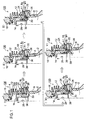
- FIG. 1 illustrates transitional phases of the engine, focused to flows of gases charged in each in-piston passage in an upstroke of the piston, in which phase (I) is the state where both a mixture window and an air window are closed by a piston skirt portion; phase (II) is the state where the mixture window communicates with an in-piston passage; phase (III) is the state where the air window above the mixture window is coming into communication with the in-piston passage while the mixture window is in communication with the in-piston passage; phase (IV) is the state where both the mixture window and the air window above it communicate with the in-piston passage; and phase (V) is the state where the air window has come into communication with the in-piston passage while the mixture window keeps communication with the crankcase and permits the air-fuel mixture to flow into the crankcase.
- phase (I) is the state where both a mixture window and an air window are closed by a piston skirt portion
- phase (II) is the state where the mixture window communicates with an in-piston
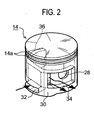
- FIG. 2 is a perspective view of the piston.
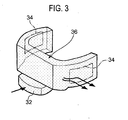
- FIG. 3 illustrates the in-piston passage formed inside the piston.
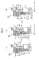
- FIG. 4 illustrates transitional phases of the engine, focused to flows of gases that are charged in the scavenging passage through the in-piston passage when the in-piston passage is brought into communication with the scavenging passage in each upstroke of the piston, in which phase (I) is the state where rich air-fuel mixture generated by the carburetor is charged in the scavenging passage; phase (II) is the state where lean air-fuel mixture diluted with air in the in-piston passage is charged in the scavenging passage; and phase (III) is the state where air is charged in the scavenging passage.
- phase (I) is the state where rich air-fuel mixture generated by the carburetor is charged in the scavenging passage
- phase (II) is the state where lean air-fuel mixture diluted with air in the in-piston passage is charged in the scavenging passage
- phase (III) is the state where air is charged in the scavenging passage.
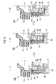
- FIG. 5 illustrates different phases of the engine in each scavenging stroke, in which phase (I) is the state where heading air is supplied to the combustion chamber; phase (II) is the state where lean air-fuel mixture is supplied to the combustion chamber next to the heading air; and phase (III) is the state where rich air-fuel mixture generated by the carburetor is supplied to the combustion chamber next to the lean air-fuel mixture.
- FIG. 6 illustrates timings for opening respective windows of the engine according to the present embodiment.
- FIG. 7 illustrates timings for opening windows in a conventional engine in comparison with the timings shown in FIG 6 .
- an air-cooled two-stroke internal combustion engine 100 is a single-cylinder, compact-sized engine to be mounted in, for example, a hand-held work apparatus such as a chain saw or a brush cutter.
- this engine 100 includes scavenging passages 6 each communicating with both a crankcase 2 and a combustion chamber 4 ( FIG. 4 ).
- the scavenging passages 6 are formed as an integral part of a cylinder block 8.
- the cylinder bore 12 has formed scavenging windows 10 each being an exit end of each scavenging passage 6.
- the scavenging windows 10 are opened and closed by reciprocal movements of the piston 14.
- the engine 100 supplies air-fuel mixture (rich air-fuel mixture in the aforementioned context of this specification) into the crankcase 2, then compresses it with the piston 14, and supplies the compressed air-fuel mixture to the combustion chamber 4 via the scavenging passages 6.
- air-fuel mixture rich air-fuel mixture in the aforementioned context of this specification
- the piston 14 compresses it with the piston 14, and supplies the compressed air-fuel mixture to the combustion chamber 4 via the scavenging passages 6.
- the engine 100 has two, one pair of, scavenging passages 6, the drawings show only one for simplicity. These scavenging passages 6 have substantially the same configuration.
- reference numeral 16 indicates an ignition plug.
- the cylinder block 8 of the engine 100 has two ports 18 and 20 at a position circumferentially intermediate between the pair of scavenging passages 6, and these two ports 18 and 20 are aligned vertically, placing a partition 22 therebetween.
- These two ports 18 and 20 are coupled to a carburetor via a flexible coupling tube, not shown. Through this coupling tube, the upper port 18 is supplied with air, and the lower port 20 is supplied with rich air-fuel mixture of a predetermined air-fuel ratio as generated by the carburetor.
- the coupling tube includes two passages inside. One of the passages is used for transporting air and communicates with the air port 18. The other of the two passages is used for transporting the air-fuel mixture and communicates with the mixture port 20.
- the air port 18 opens to the cylinder bore 12 at the air window 24.
- the mixture port 20 opens to the cylinder bore 12 at the mixture window 26.
- the air window 24 and the mixture window 26 are opened and closed by strokes of the piston 14.
- FIG. 2 is a perspective view of the piston 14. As illustrated in FIG. 2 , a plurality of annular piston ring grooves 14a are formed at an the upper end portion of the outer circumferential surface of the piston 14 to receive piston rings are fitted (not shown) therein as in conventional engines. At a lengthwise intermediate position of the piston 14, a piston pin hole 28 is formed to receive a piston pin (not shown), which connects the piston 14 to a small end of a connecting rod (not shown). The piston pin hole 28 extends, penetrating the piston in the radial direction.
- the piston 14 has formed a first aperture 32 and two second apertures 34 at its skirt part 30.
- the second apertures 34, 34 are formed respectively at locations corresponding to two opposite ends of the piston pin hole 28.
- the first aperture 32 is formed at a location intersecting with the piston pin hole 28 at the lower end of the skirt part 30.
- the first aperture 32 and the second apertures 34 communicate with one another via an in-piston passage 36 formed inside the piston 14.
- FIG. 3 illustrates the configuration of the in-piston passage 36.
- FIG. 1 and FIG. 4 show no exhaust port, but the cylinder block 8 has formed an exhaust port as conventional ones, and this exhaust port communicates with the cylinder bore 12 through an exhaust window.
- the exhaust window is opened and closed by reciprocal strokes of the piston 14 as in conventional engines.
- FIG. 6 is a diagram for explaining timings for charging gases in each scavenging passage 6 through the in-piston passage 36 in relation to specific crank angles. The angles appearing in FIG. 6 indicate these crank angles.
- the exhaust window In the process of a downstroke of the piston 14 toward the bottom dead center and an upstroke from the bottom dead center, the exhaust window is opened, and burned gas within the combustion chamber 4 is discharged to the outside through the exhaust port.
- the angular range in which the exhaust window is opened is 141.3 degrees (see Exhaust Window in FIG. 6 ). Scavenging, i.e., opening of the scavenging windows 10 of the scavenging passages 6, takes place in the angular range of 109.1 degrees (see Scavenging Window in FIG. 6 ) within the said angular range of 141.3 degrees for exhaustion..
- the mixture window 26 of the mixture port 20 is opened in the angular range of 128.5 degrees (see “Mix Window” in FIG. 6 ) and allowed to communicate with the in-piston passage 36.
- the in-piston passage 36 communicates with the scavenging passage 6 as well in this angular range of 128.5 degrees.
- the mixture window 26 is closed in the angular range of 56.7 degrees (see the part shown by chain double-dashed lines in the arc of "Mix Window” in FIG. 6 ) within this range of 128.5 degrees.
- the air window 24 of the air port 18 is opened in the angular range of 88.3 degrees (see “Air Window” in FIG. 6 ) and allowed to communicate with the in-piston passage 36.
- the mixture port 20 opens into the crankcase 2 in the same angular range of 88.3 degrees (see “Mix to Crankcase” in FIG. 6 ).
- the engine is configured such that the scavenging passages 6 are charged with rich air-fuel mixture through the in-piston passage 36 before the air-fuel mixture enters into the crankcase 2 from the mixture port 20. Therefore, by the use of negative pressure in the crankcase 2, the air-fuel mixture can be readily drawn into the scavenging passages 6 through the in-piston passage 36.
- a negative pressure is produced and increased in the crankcase 2, and this negative pressure acts to reduce the pressure in the scavenging passages 6 as well.
- the air-fuel mixture alone is first supplied through the mixture window 26 into the in-piston passage 36 by using the negative pressure in the crankcase 2 in each upstroke of the piston 14 (phase (II) of FIG. 1 ).
- phase (II) of FIG. 1 Next supplied are both the air-fuel mixture from the mixture window 26 and the air from the air window 24 (phase (III) and phase (IV) of FIG. 1 ).
- the air alone is supplied from the air window 24 (phase (V) of FIG. 1 ). In the period of phase (III) and phase (IV) of FIG.
- phase (III) and phase (IV) of FIG. 1 since the air-fuel mixture and the air are supplied concurrently into the in-piston passage 36, the air-fuel mixture is mixed with the air in the in-piston passage 36. Therefore, in phase (III) and phase (IV) of FIG. 1 , the air-fuel mixture heretofore having the predetermined air-fuel ratio as generated by the carburetor is diluted in the in-piston passage 36 and changed to lean air-fuel mixture containing a relatively small amount of fuel component.
- the air-fuel mixture of the predetermined air-fuel ratio generated by the carburetor is first charged into the scavenging passages 6 through the in-piston passage 36 in each upstroke of the piston 14 (phase (I) of FIG. 4 ).
- this air-fuel mixture is called herein "rich air-fuel mixture” (see “Rich Mix” in phase (II) and phase (III) of FIG. 4 ) because it is richer in fuel component than the lean air-fuel mixture.
- air-fuel mixture prepared by diluting rich air-fuel mixture with air in the in-piston passage 36 is charged (phase (II) of FIG. 4 ).
- This air-fuel mixture is herein referred to as “lean mixture” (see “Lean Mix” in phase (II) and phase (III) of FIG. 4 ) as well.
- air is supplied (phase (III) of FIG. 4 ).
- reference numeral 40 indicates the air in the scavenging passage 6
- reference numeral 42 indicates the lean air-fuel mixture
- reference numeral 44 indicates the rich air-fuel mixture.
- FIG. 5 shows the statuses in which the piston 14 has moved to levels opening the scavenging window 10 of the scavenging passage 6 gradually wider to the combustion chamber 4 in each downstroke of the piston 14 toward the bottom dead center.
- the air 40 occupies the space of the scavenging passage 6 from its exit, i.e. the scavenging window, up to near the inlet (opening to the crankcase 2), and the lean air-fuel mixture 42 occupies the space around the inlet of the scavenging passage 6.
- the air 40 within the scavenging passage 6 is supplied into the combustion chamber 4, and this air 40 is used for scavenging (phase (I) of FIG. 5 ).
- the lean air-fuel mixture 42 is supplied into the combustion chamber 4 (phase (II) of FIG. 5 ).
- the rich air-fuel mixture 44 is supplied from the crankcase 2 as in conventional like systems. That is, the air-fuel mixture of the predetermined air-fuel ratio as generated by the carburetor is supplied into the combustion chamber 4 (phase (III) of FIG. 5 ).
- the heading air 40 flowing out of the scavenging passage 6 into the combustion chamber 4 is used for scavenging. Even though some blow-by of air-fuel mixture occurs, this method can reduce the outflow amount of the fuel component due to the blow-by. This is because it is the lean air-fuel mixture that is supplied into the combustion chamber 4 following to the heading air, and the lean air-fuel mixture that possibly flows out of the combustion chamber 4 contains only a small amount of fuel component.
- the scavenging passage 6 when the scavenging passage 6 is charged with gases, they are supplied in the order of the rich air-fuel mixture, the lean air-fuel mixture and the air. Therefore, it is the air-fuel mixture that collides and may mix with the air-fuel mixture existing in the crankcase 2. Additionally, the lean air-fuel mixture exists as a buffer behind the rich air-fuel mixture and in front of the air. Therefore, this method significantly reduces the possibility that the air mixes with the fuel component in the process of charging the gases in the scavenging passage 6.
- the method of the present invention can use a more amount of air for the intended purpose of scavenging.
- this method can significantly reduce fluctuations in air-fuel ratio of the air-fuel mixture in the crankcase 2, which may otherwise occur due to intrusion of air for scavenging.
- the engine is improved in response to sudden acceleration.
- FIG. 7 is a diagram showing timings of charging gases in a conventional two-stroke internal combustion engine of an air-headed scavenging type.
- the mixture port 20 communicating with the crankcase 2 is opened in the angular range of 128.5 degrees in this conventional engine.
- the embodiment of the present invention already explained with reference to FIG. 6 has apparently unique features significantly different from the conventional ones. More specifically, in FIG. 6 of the present invention, the mixture port 20 is opened to the crankcase 2 in the much smaller angular range of 88.3 degrees. Only in this angular range, the lean Mix (which is a result of concurrent introduction of the air-fuel mixture and the air into the in-piston passage 36) and the air are allowed to flow into the in-piston passage 36.
- the in-piston passage 36 as well, communicates only in this angular range.
- the timing for the air to enter into the in-piston passage 36 is synchronous with the timing for air-fuel mixture to enter into the crankcase 2 directly from the mixture port 20. Therefore, it is possible to alleviate unexpected fluctuations of the negative pressure in the crankcase 2, which acts to draw the air into the scavenging passage 6 through the in-piston passage 36, and to thereby reduce instability of flow rate and timing for the air that enters into the scavenging passage 6.
- crankcase 2 is first charged with the air-fuel mixture through the in-piston passage 36 and the scavenging passage 6, and immediately thereafter without interruption, the crankcase 2 is charged with the air-fuel mixture directly from the mixture port 20, not via the scavenging passage 6.
- this method executes, consecutively without interruption, the process of charging the crankcase 2 with the air-fuel mixture through the in-piston passage 36 and the scavenging passage 6, and the process for charging the crankcase 2 with the air-fuel mixture directly from the mixture port 20. Therefore, fluctuations of the air-fuel ratio in the crankcase 2, if any, can be reduced in this serial charging of the air-fuel mixture into the crankcase 2.
- the present invention is applicable to small-sized two-stroke internal combustion engines for use in work apparatuses such as chain saws and brush cutters.
Landscapes
- Engineering & Computer Science (AREA)
- Chemical & Material Sciences (AREA)
- Combustion & Propulsion (AREA)
- Mechanical Engineering (AREA)
- General Engineering & Computer Science (AREA)
- Electrical Control Of Air Or Fuel Supplied To Internal-Combustion Engine (AREA)
- Combustion Methods Of Internal-Combustion Engines (AREA)
- Supercharger (AREA)
Applications Claiming Priority (1)
| Application Number | Priority Date | Filing Date | Title |
|---|---|---|---|
| JP2010012551A JP5478272B2 (ja) | 2010-01-22 | 2010-01-22 | 2ストローク内燃エンジン及びその掃気方法 |
Publications (3)
| Publication Number | Publication Date |
|---|---|
| EP2348208A2 EP2348208A2 (en) | 2011-07-27 |
| EP2348208A3 EP2348208A3 (en) | 2012-08-22 |
| EP2348208B1 true EP2348208B1 (en) | 2014-11-12 |
Family
ID=43772280
Family Applications (1)
| Application Number | Title | Priority Date | Filing Date |
|---|---|---|---|
| EP11151661.3A Not-in-force EP2348208B1 (en) | 2010-01-22 | 2011-01-21 | Two-stroke internal combustion engine and its scavenging method |
Country Status (3)
| Country | Link |
|---|---|
| US (1) | US8746192B2 (enExample) |
| EP (1) | EP2348208B1 (enExample) |
| JP (1) | JP5478272B2 (enExample) |
Cited By (1)
| Publication number | Priority date | Publication date | Assignee | Title |
|---|---|---|---|---|
| CN109312689A (zh) * | 2016-06-14 | 2019-02-05 | 意玛克股份公司 | 二冲程内燃发动机 |
Families Citing this family (2)
| Publication number | Priority date | Publication date | Assignee | Title |
|---|---|---|---|---|
| CN111810313A (zh) * | 2020-06-02 | 2020-10-23 | 浙江派尼尔科技股份有限公司 | 一种分层扫气活塞 |
| CN113107662A (zh) * | 2021-05-08 | 2021-07-13 | 永康市茂金园林机械有限公司 | 一种用于分层扫气二冲程发动机的汽缸活塞单元 |
Family Cites Families (21)
| Publication number | Priority date | Publication date | Assignee | Title |
|---|---|---|---|---|
| DE69820443T2 (de) | 1997-06-11 | 2004-10-07 | Komatsu Zenoa Kk | Schichtspülung für zweitaktmotoren |
| JPH1182081A (ja) * | 1997-08-29 | 1999-03-26 | Masatoshi Hirano | 内燃機関 |
| US6257179B1 (en) | 1999-04-28 | 2001-07-10 | Mitsubishi Heavy Industries, Ltd. | Two-stroke cycle engine |
| JP4153643B2 (ja) | 1999-04-28 | 2008-09-24 | 三菱重工業株式会社 | 層状掃気2サイクルエンジン及びディスクバルブ装置 |
| JP2001239463A (ja) | 2000-02-25 | 2001-09-04 | Xebec Technology Co Ltd | ラッピング材 |
| US6418891B2 (en) | 2000-03-13 | 2002-07-16 | Walbro Japan, Inc. | Internal combustion engine |
| JP2001323816A (ja) * | 2000-05-16 | 2001-11-22 | Kioritz Corp | 2サイクル内燃エンジン |
| JP2001355450A (ja) | 2000-06-12 | 2001-12-26 | Walbro Japan Inc | 層状掃気2行程内燃機関 |
| US6591794B2 (en) | 2000-10-24 | 2003-07-15 | Zama Japan | Air-fuel ratio control system for a stratified scavenging two-cycle engine |
| DE10064719B4 (de) * | 2000-12-22 | 2013-12-12 | Andreas Stihl Ag & Co. | Zweitaktmotor mit Ladungsschichtung |
| AUPR283501A0 (en) | 2001-02-01 | 2001-02-22 | Notaras, John Arthur | Internal combustion engine |
| JP3616339B2 (ja) * | 2001-02-01 | 2005-02-02 | 株式会社共立 | 2サイクル内燃エンジン |
| DE10301732B4 (de) * | 2003-01-18 | 2020-01-30 | Andreas Stihl Ag & Co. Kg | Zweitaktmotor und Verfahren zu dessen Betrieb |
| DE10341230B4 (de) * | 2003-09-08 | 2022-10-13 | Andreas Stihl Ag & Co. Kg | Ansaugvorrichtung |
| US7093570B2 (en) * | 2003-12-31 | 2006-08-22 | Nagesh S Mavinahally | Stratified scavenged two-stroke engine |
| JP4317086B2 (ja) * | 2004-07-08 | 2009-08-19 | 川崎重工業株式会社 | 減圧装置を備えた空気掃気型エンジン |
| US7331315B2 (en) * | 2005-02-23 | 2008-02-19 | Eastway Fair Company Limited | Two-stroke engine with fuel injection |
| US20060243230A1 (en) | 2005-03-23 | 2006-11-02 | Mavinahally Nagesh S | Two-stroke engine |
| US7325791B2 (en) | 2005-09-15 | 2008-02-05 | Zama Japan Co., Ltd. | Carburetor for stratified scavenging two-cycle engine |
| JP2007239463A (ja) | 2006-03-03 | 2007-09-20 | Komatsu Zenoah Co | 2サイクルエンジン |
| JP5236368B2 (ja) | 2008-07-03 | 2013-07-17 | ファナック株式会社 | 単一電源を備えたワイヤ放電加工機 |
-
2010
- 2010-01-22 JP JP2010012551A patent/JP5478272B2/ja not_active Expired - Fee Related
-
2011
- 2011-01-21 US US13/010,860 patent/US8746192B2/en not_active Expired - Fee Related
- 2011-01-21 EP EP11151661.3A patent/EP2348208B1/en not_active Not-in-force
Cited By (2)
| Publication number | Priority date | Publication date | Assignee | Title |
|---|---|---|---|---|
| CN109312689A (zh) * | 2016-06-14 | 2019-02-05 | 意玛克股份公司 | 二冲程内燃发动机 |
| CN109312689B (zh) * | 2016-06-14 | 2021-08-17 | 意玛克股份公司 | 二冲程内燃发动机 |
Also Published As
| Publication number | Publication date |
|---|---|
| US20110180054A1 (en) | 2011-07-28 |
| EP2348208A2 (en) | 2011-07-27 |
| EP2348208A3 (en) | 2012-08-22 |
| US8746192B2 (en) | 2014-06-10 |
| JP5478272B2 (ja) | 2014-04-23 |
| JP2011149375A (ja) | 2011-08-04 |
Similar Documents
| Publication | Publication Date | Title |
|---|---|---|
| EP2775118B1 (en) | Stratified scavenging two-stroke engine | |
| US3934562A (en) | Two-cycle engine | |
| EP3006692B1 (en) | Air leading-type stratified scavenging two-stroke internal-combustion engine | |
| US9816431B2 (en) | Stratified scavenging two-cycle engine | |
| US20160053667A1 (en) | Prechamber assembly for an engine | |
| EP4534812A1 (en) | Hydrogen engine | |
| EP2348208B1 (en) | Two-stroke internal combustion engine and its scavenging method | |
| US20110079206A1 (en) | Two-stroke engine | |
| JPH0563605B2 (enExample) | ||
| EP1967722A1 (en) | Two-cycle engine | |
| US6450135B1 (en) | Two-stroke internal combustion engine | |
| JPH0112926B2 (enExample) | ||
| US5947066A (en) | Two-cycle internal combustion engine | |
| US7322322B2 (en) | Stratified-scavenging two-stroke internal combustion engine | |
| US6591793B2 (en) | Two-cycle engine | |
| US20190170055A1 (en) | Two-stroke engine with improved performance | |
| US6895909B2 (en) | Two-cycle combustion engine having two-staged piston | |
| US6145483A (en) | Two-cycle internal combustion engine | |
| US6591792B2 (en) | Two-cycle engine | |
| US9726070B2 (en) | Stratified scavenging two-stroke engine | |
| JP2561593B2 (ja) | 段付ピストンを有する複数気筒の2サイクルエンジン | |
| US20120006308A1 (en) | Piston for a Two-Stroke Engine | |
| JP2001140650A (ja) | 2サイクルエンジン | |
| JPH1077845A (ja) | 2サイクルエンジンの構造 | |
| JPH05118225A (ja) | 段付ピストンを有する2サイクルエンジン |
Legal Events
| Date | Code | Title | Description |
|---|---|---|---|
| PUAI | Public reference made under article 153(3) epc to a published international application that has entered the european phase |
Free format text: ORIGINAL CODE: 0009012 |
|
| AK | Designated contracting states |
Kind code of ref document: A2 Designated state(s): AL AT BE BG CH CY CZ DE DK EE ES FI FR GB GR HR HU IE IS IT LI LT LU LV MC MK MT NL NO PL PT RO RS SE SI SK SM TR |
|
| AX | Request for extension of the european patent |
Extension state: BA ME |
|
| PUAL | Search report despatched |
Free format text: ORIGINAL CODE: 0009013 |
|
| AK | Designated contracting states |
Kind code of ref document: A3 Designated state(s): AL AT BE BG CH CY CZ DE DK EE ES FI FR GB GR HR HU IE IS IT LI LT LU LV MC MK MT NL NO PL PT RO RS SE SI SK SM TR |
|
| AX | Request for extension of the european patent |
Extension state: BA ME |
|
| RIC1 | Information provided on ipc code assigned before grant |
Ipc: F02B 25/20 20060101AFI20120716BHEP |
|
| 17P | Request for examination filed |
Effective date: 20130221 |
|
| GRAP | Despatch of communication of intention to grant a patent |
Free format text: ORIGINAL CODE: EPIDOSNIGR1 |
|
| INTG | Intention to grant announced |
Effective date: 20140116 |
|
| GRAP | Despatch of communication of intention to grant a patent |
Free format text: ORIGINAL CODE: EPIDOSNIGR1 |
|
| INTG | Intention to grant announced |
Effective date: 20140523 |
|
| GRAS | Grant fee paid |
Free format text: ORIGINAL CODE: EPIDOSNIGR3 |
|
| GRAA | (expected) grant |
Free format text: ORIGINAL CODE: 0009210 |
|
| AK | Designated contracting states |
Kind code of ref document: B1 Designated state(s): AL AT BE BG CH CY CZ DE DK EE ES FI FR GB GR HR HU IE IS IT LI LT LU LV MC MK MT NL NO PL PT RO RS SE SI SK SM TR |
|
| RAP1 | Party data changed (applicant data changed or rights of an application transferred) |
Owner name: YAMABIKO CORPORATION |
|
| REG | Reference to a national code |
Ref country code: GB Ref legal event code: FG4D |
|
| REG | Reference to a national code |
Ref country code: CH Ref legal event code: EP |
|
| REG | Reference to a national code |
Ref country code: AT Ref legal event code: REF Ref document number: 695921 Country of ref document: AT Kind code of ref document: T Effective date: 20141115 |
|
| REG | Reference to a national code |
Ref country code: IE Ref legal event code: FG4D |
|
| REG | Reference to a national code |
Ref country code: DE Ref legal event code: R096 Ref document number: 602011011226 Country of ref document: DE Effective date: 20141224 |
|
| REG | Reference to a national code |
Ref country code: NL Ref legal event code: VDEP Effective date: 20141112 |
|
| REG | Reference to a national code |
Ref country code: AT Ref legal event code: MK05 Ref document number: 695921 Country of ref document: AT Kind code of ref document: T Effective date: 20141112 |
|
| PG25 | Lapsed in a contracting state [announced via postgrant information from national office to epo] |
Ref country code: FI Free format text: LAPSE BECAUSE OF FAILURE TO SUBMIT A TRANSLATION OF THE DESCRIPTION OR TO PAY THE FEE WITHIN THE PRESCRIBED TIME-LIMIT Effective date: 20141112 Ref country code: ES Free format text: LAPSE BECAUSE OF FAILURE TO SUBMIT A TRANSLATION OF THE DESCRIPTION OR TO PAY THE FEE WITHIN THE PRESCRIBED TIME-LIMIT Effective date: 20141112 Ref country code: NL Free format text: LAPSE BECAUSE OF FAILURE TO SUBMIT A TRANSLATION OF THE DESCRIPTION OR TO PAY THE FEE WITHIN THE PRESCRIBED TIME-LIMIT Effective date: 20141112 Ref country code: PT Free format text: LAPSE BECAUSE OF FAILURE TO SUBMIT A TRANSLATION OF THE DESCRIPTION OR TO PAY THE FEE WITHIN THE PRESCRIBED TIME-LIMIT Effective date: 20150312 Ref country code: NO Free format text: LAPSE BECAUSE OF FAILURE TO SUBMIT A TRANSLATION OF THE DESCRIPTION OR TO PAY THE FEE WITHIN THE PRESCRIBED TIME-LIMIT Effective date: 20150212 Ref country code: IS Free format text: LAPSE BECAUSE OF FAILURE TO SUBMIT A TRANSLATION OF THE DESCRIPTION OR TO PAY THE FEE WITHIN THE PRESCRIBED TIME-LIMIT Effective date: 20150312 Ref country code: LT Free format text: LAPSE BECAUSE OF FAILURE TO SUBMIT A TRANSLATION OF THE DESCRIPTION OR TO PAY THE FEE WITHIN THE PRESCRIBED TIME-LIMIT Effective date: 20141112 |
|
| REG | Reference to a national code |
Ref country code: DE Ref legal event code: R082 Ref document number: 602011011226 Country of ref document: DE Representative=s name: SCHAUMBURG & PARTNER PATENTANWAELTE GBR, DE Ref country code: DE Ref legal event code: R082 Ref document number: 602011011226 Country of ref document: DE Representative=s name: SCHAUMBURG & PARTNER PATENTANWAELTE MBB, DE Ref country code: DE Ref legal event code: R082 Ref document number: 602011011226 Country of ref document: DE Representative=s name: SCHAUMBURG UND PARTNER PATENTANWAELTE MBB, DE |
|
| PG25 | Lapsed in a contracting state [announced via postgrant information from national office to epo] |
Ref country code: PL Free format text: LAPSE BECAUSE OF FAILURE TO SUBMIT A TRANSLATION OF THE DESCRIPTION OR TO PAY THE FEE WITHIN THE PRESCRIBED TIME-LIMIT Effective date: 20141112 Ref country code: CY Free format text: LAPSE BECAUSE OF FAILURE TO SUBMIT A TRANSLATION OF THE DESCRIPTION OR TO PAY THE FEE WITHIN THE PRESCRIBED TIME-LIMIT Effective date: 20141112 Ref country code: HR Free format text: LAPSE BECAUSE OF FAILURE TO SUBMIT A TRANSLATION OF THE DESCRIPTION OR TO PAY THE FEE WITHIN THE PRESCRIBED TIME-LIMIT Effective date: 20141112 Ref country code: LV Free format text: LAPSE BECAUSE OF FAILURE TO SUBMIT A TRANSLATION OF THE DESCRIPTION OR TO PAY THE FEE WITHIN THE PRESCRIBED TIME-LIMIT Effective date: 20141112 Ref country code: GR Free format text: LAPSE BECAUSE OF FAILURE TO SUBMIT A TRANSLATION OF THE DESCRIPTION OR TO PAY THE FEE WITHIN THE PRESCRIBED TIME-LIMIT Effective date: 20150213 Ref country code: AT Free format text: LAPSE BECAUSE OF FAILURE TO SUBMIT A TRANSLATION OF THE DESCRIPTION OR TO PAY THE FEE WITHIN THE PRESCRIBED TIME-LIMIT Effective date: 20141112 Ref country code: SE Free format text: LAPSE BECAUSE OF FAILURE TO SUBMIT A TRANSLATION OF THE DESCRIPTION OR TO PAY THE FEE WITHIN THE PRESCRIBED TIME-LIMIT Effective date: 20141112 Ref country code: RS Free format text: LAPSE BECAUSE OF FAILURE TO SUBMIT A TRANSLATION OF THE DESCRIPTION OR TO PAY THE FEE WITHIN THE PRESCRIBED TIME-LIMIT Effective date: 20141112 |
|
| PG25 | Lapsed in a contracting state [announced via postgrant information from national office to epo] |
Ref country code: EE Free format text: LAPSE BECAUSE OF FAILURE TO SUBMIT A TRANSLATION OF THE DESCRIPTION OR TO PAY THE FEE WITHIN THE PRESCRIBED TIME-LIMIT Effective date: 20141112 Ref country code: CZ Free format text: LAPSE BECAUSE OF FAILURE TO SUBMIT A TRANSLATION OF THE DESCRIPTION OR TO PAY THE FEE WITHIN THE PRESCRIBED TIME-LIMIT Effective date: 20141112 Ref country code: RO Free format text: LAPSE BECAUSE OF FAILURE TO SUBMIT A TRANSLATION OF THE DESCRIPTION OR TO PAY THE FEE WITHIN THE PRESCRIBED TIME-LIMIT Effective date: 20141112 Ref country code: DK Free format text: LAPSE BECAUSE OF FAILURE TO SUBMIT A TRANSLATION OF THE DESCRIPTION OR TO PAY THE FEE WITHIN THE PRESCRIBED TIME-LIMIT Effective date: 20141112 Ref country code: SK Free format text: LAPSE BECAUSE OF FAILURE TO SUBMIT A TRANSLATION OF THE DESCRIPTION OR TO PAY THE FEE WITHIN THE PRESCRIBED TIME-LIMIT Effective date: 20141112 |
|
| REG | Reference to a national code |
Ref country code: DE Ref legal event code: R097 Ref document number: 602011011226 Country of ref document: DE |
|
| REG | Reference to a national code |
Ref country code: CH Ref legal event code: PL |
|
| PG25 | Lapsed in a contracting state [announced via postgrant information from national office to epo] |
Ref country code: LU Free format text: LAPSE BECAUSE OF FAILURE TO SUBMIT A TRANSLATION OF THE DESCRIPTION OR TO PAY THE FEE WITHIN THE PRESCRIBED TIME-LIMIT Effective date: 20150121 |
|
| PLBE | No opposition filed within time limit |
Free format text: ORIGINAL CODE: 0009261 |
|
| STAA | Information on the status of an ep patent application or granted ep patent |
Free format text: STATUS: NO OPPOSITION FILED WITHIN TIME LIMIT |
|
| PG25 | Lapsed in a contracting state [announced via postgrant information from national office to epo] |
Ref country code: MC Free format text: LAPSE BECAUSE OF FAILURE TO SUBMIT A TRANSLATION OF THE DESCRIPTION OR TO PAY THE FEE WITHIN THE PRESCRIBED TIME-LIMIT Effective date: 20141112 |
|
| 26N | No opposition filed |
Effective date: 20150813 |
|
| GBPC | Gb: european patent ceased through non-payment of renewal fee |
Effective date: 20150212 |
|
| PG25 | Lapsed in a contracting state [announced via postgrant information from national office to epo] |
Ref country code: LI Free format text: LAPSE BECAUSE OF NON-PAYMENT OF DUE FEES Effective date: 20150131 Ref country code: CH Free format text: LAPSE BECAUSE OF NON-PAYMENT OF DUE FEES Effective date: 20150131 |
|
| REG | Reference to a national code |
Ref country code: IE Ref legal event code: MM4A |
|
| REG | Reference to a national code |
Ref country code: FR Ref legal event code: PLFP Year of fee payment: 6 |
|
| PG25 | Lapsed in a contracting state [announced via postgrant information from national office to epo] |
Ref country code: GB Free format text: LAPSE BECAUSE OF NON-PAYMENT OF DUE FEES Effective date: 20150212 Ref country code: IE Free format text: LAPSE BECAUSE OF NON-PAYMENT OF DUE FEES Effective date: 20150121 |
|
| PG25 | Lapsed in a contracting state [announced via postgrant information from national office to epo] |
Ref country code: SI Free format text: LAPSE BECAUSE OF FAILURE TO SUBMIT A TRANSLATION OF THE DESCRIPTION OR TO PAY THE FEE WITHIN THE PRESCRIBED TIME-LIMIT Effective date: 20141112 |
|
| PGFP | Annual fee paid to national office [announced via postgrant information from national office to epo] |
Ref country code: DE Payment date: 20160224 Year of fee payment: 6 Ref country code: IT Payment date: 20160122 Year of fee payment: 6 |
|
| PGFP | Annual fee paid to national office [announced via postgrant information from national office to epo] |
Ref country code: FR Payment date: 20160121 Year of fee payment: 6 |
|
| PG25 | Lapsed in a contracting state [announced via postgrant information from national office to epo] |
Ref country code: MT Free format text: LAPSE BECAUSE OF FAILURE TO SUBMIT A TRANSLATION OF THE DESCRIPTION OR TO PAY THE FEE WITHIN THE PRESCRIBED TIME-LIMIT Effective date: 20141112 |
|
| PG25 | Lapsed in a contracting state [announced via postgrant information from national office to epo] |
Ref country code: HU Free format text: LAPSE BECAUSE OF FAILURE TO SUBMIT A TRANSLATION OF THE DESCRIPTION OR TO PAY THE FEE WITHIN THE PRESCRIBED TIME-LIMIT; INVALID AB INITIO Effective date: 20110121 Ref country code: BG Free format text: LAPSE BECAUSE OF FAILURE TO SUBMIT A TRANSLATION OF THE DESCRIPTION OR TO PAY THE FEE WITHIN THE PRESCRIBED TIME-LIMIT Effective date: 20141112 Ref country code: SM Free format text: LAPSE BECAUSE OF FAILURE TO SUBMIT A TRANSLATION OF THE DESCRIPTION OR TO PAY THE FEE WITHIN THE PRESCRIBED TIME-LIMIT Effective date: 20141112 |
|
| PG25 | Lapsed in a contracting state [announced via postgrant information from national office to epo] |
Ref country code: BE Free format text: LAPSE BECAUSE OF NON-PAYMENT OF DUE FEES Effective date: 20150131 |
|
| REG | Reference to a national code |
Ref country code: DE Ref legal event code: R119 Ref document number: 602011011226 Country of ref document: DE |
|
| PG25 | Lapsed in a contracting state [announced via postgrant information from national office to epo] |
Ref country code: TR Free format text: LAPSE BECAUSE OF FAILURE TO SUBMIT A TRANSLATION OF THE DESCRIPTION OR TO PAY THE FEE WITHIN THE PRESCRIBED TIME-LIMIT Effective date: 20141112 |
|
| REG | Reference to a national code |
Ref country code: FR Ref legal event code: ST Effective date: 20170929 |
|
| PG25 | Lapsed in a contracting state [announced via postgrant information from national office to epo] |
Ref country code: FR Free format text: LAPSE BECAUSE OF NON-PAYMENT OF DUE FEES Effective date: 20170131 |
|
| PG25 | Lapsed in a contracting state [announced via postgrant information from national office to epo] |
Ref country code: DE Free format text: LAPSE BECAUSE OF NON-PAYMENT OF DUE FEES Effective date: 20170801 |
|
| PG25 | Lapsed in a contracting state [announced via postgrant information from national office to epo] |
Ref country code: IT Free format text: LAPSE BECAUSE OF NON-PAYMENT OF DUE FEES Effective date: 20170121 |
|
| PG25 | Lapsed in a contracting state [announced via postgrant information from national office to epo] |
Ref country code: MK Free format text: LAPSE BECAUSE OF FAILURE TO SUBMIT A TRANSLATION OF THE DESCRIPTION OR TO PAY THE FEE WITHIN THE PRESCRIBED TIME-LIMIT Effective date: 20141112 |
|
| PG25 | Lapsed in a contracting state [announced via postgrant information from national office to epo] |
Ref country code: AL Free format text: LAPSE BECAUSE OF FAILURE TO SUBMIT A TRANSLATION OF THE DESCRIPTION OR TO PAY THE FEE WITHIN THE PRESCRIBED TIME-LIMIT Effective date: 20141112 |