EP2346232B1 - Tragbares Endgerät mit einer Eingabevorrichtung - Google Patents
Tragbares Endgerät mit einer Eingabevorrichtung Download PDFInfo
- Publication number
- EP2346232B1 EP2346232B1 EP20100175195 EP10175195A EP2346232B1 EP 2346232 B1 EP2346232 B1 EP 2346232B1 EP 20100175195 EP20100175195 EP 20100175195 EP 10175195 A EP10175195 A EP 10175195A EP 2346232 B1 EP2346232 B1 EP 2346232B1
- Authority
- EP
- European Patent Office
- Prior art keywords
- input
- mobile terminal
- touch
- light
- key button
- Prior art date
- Legal status (The legal status is an assumption and is not a legal conclusion. Google has not performed a legal analysis and makes no representation as to the accuracy of the status listed.)
- Not-in-force
Links
Images


Classifications
-
- H—ELECTRICITY
- H04—ELECTRIC COMMUNICATION TECHNIQUE
- H04M—TELEPHONIC COMMUNICATION
- H04M1/00—Substation equipment, e.g. for use by subscribers
- H04M1/02—Constructional features of telephone sets
- H04M1/23—Construction or mounting of dials or of equivalent devices; Means for facilitating the use thereof
- H04M1/233—Construction or mounting of dials or of equivalent devices; Means for facilitating the use thereof including a pointing device, e.g. roller key, track ball, rocker switch or joystick
-
- G—PHYSICS
- G06—COMPUTING; CALCULATING OR COUNTING
- G06F—ELECTRIC DIGITAL DATA PROCESSING
- G06F1/00—Details not covered by groups G06F3/00 - G06F13/00 and G06F21/00
- G06F1/16—Constructional details or arrangements
- G06F1/1613—Constructional details or arrangements for portable computers
- G06F1/1633—Constructional details or arrangements of portable computers not specific to the type of enclosures covered by groups G06F1/1615 - G06F1/1626
- G06F1/1662—Details related to the integrated keyboard
-
- G—PHYSICS
- G06—COMPUTING; CALCULATING OR COUNTING
- G06F—ELECTRIC DIGITAL DATA PROCESSING
- G06F1/00—Details not covered by groups G06F3/00 - G06F13/00 and G06F21/00
- G06F1/16—Constructional details or arrangements
- G06F1/1613—Constructional details or arrangements for portable computers
- G06F1/1633—Constructional details or arrangements of portable computers not specific to the type of enclosures covered by groups G06F1/1615 - G06F1/1626
- G06F1/1684—Constructional details or arrangements related to integrated I/O peripherals not covered by groups G06F1/1635 - G06F1/1675
- G06F1/169—Constructional details or arrangements related to integrated I/O peripherals not covered by groups G06F1/1635 - G06F1/1675 the I/O peripheral being an integrated pointing device, e.g. trackball in the palm rest area, mini-joystick integrated between keyboard keys, touch pads or touch stripes
-
- G—PHYSICS
- G06—COMPUTING; CALCULATING OR COUNTING
- G06F—ELECTRIC DIGITAL DATA PROCESSING
- G06F3/00—Input arrangements for transferring data to be processed into a form capable of being handled by the computer; Output arrangements for transferring data from processing unit to output unit, e.g. interface arrangements
- G06F3/01—Input arrangements or combined input and output arrangements for interaction between user and computer
- G06F3/03—Arrangements for converting the position or the displacement of a member into a coded form
- G06F3/041—Digitisers, e.g. for touch screens or touch pads, characterised by the transducing means
- G06F3/042—Digitisers, e.g. for touch screens or touch pads, characterised by the transducing means by opto-electronic means
- G06F3/0421—Digitisers, e.g. for touch screens or touch pads, characterised by the transducing means by opto-electronic means by interrupting or reflecting a light beam, e.g. optical touch-screen
-
- G—PHYSICS
- G06—COMPUTING; CALCULATING OR COUNTING
- G06F—ELECTRIC DIGITAL DATA PROCESSING
- G06F3/00—Input arrangements for transferring data to be processed into a form capable of being handled by the computer; Output arrangements for transferring data from processing unit to output unit, e.g. interface arrangements
- G06F3/01—Input arrangements or combined input and output arrangements for interaction between user and computer
- G06F3/048—Interaction techniques based on graphical user interfaces [GUI]
- G06F3/0487—Interaction techniques based on graphical user interfaces [GUI] using specific features provided by the input device, e.g. functions controlled by the rotation of a mouse with dual sensing arrangements, or of the nature of the input device, e.g. tap gestures based on pressure sensed by a digitiser
- G06F3/0488—Interaction techniques based on graphical user interfaces [GUI] using specific features provided by the input device, e.g. functions controlled by the rotation of a mouse with dual sensing arrangements, or of the nature of the input device, e.g. tap gestures based on pressure sensed by a digitiser using a touch-screen or digitiser, e.g. input of commands through traced gestures
- G06F3/04883—Interaction techniques based on graphical user interfaces [GUI] using specific features provided by the input device, e.g. functions controlled by the rotation of a mouse with dual sensing arrangements, or of the nature of the input device, e.g. tap gestures based on pressure sensed by a digitiser using a touch-screen or digitiser, e.g. input of commands through traced gestures for inputting data by handwriting, e.g. gesture or text
-
- H—ELECTRICITY
- H03—ELECTRONIC CIRCUITRY
- H03K—PULSE TECHNIQUE
- H03K17/00—Electronic switching or gating, i.e. not by contact-making and –breaking
- H03K17/94—Electronic switching or gating, i.e. not by contact-making and –breaking characterised by the way in which the control signals are generated
- H03K17/96—Touch switches
- H03K17/9627—Optical touch switches
- H03K17/9631—Optical touch switches using a light source as part of the switch
-
- H—ELECTRICITY
- H04—ELECTRIC COMMUNICATION TECHNIQUE
- H04M—TELEPHONIC COMMUNICATION
- H04M1/00—Substation equipment, e.g. for use by subscribers
- H04M1/02—Constructional features of telephone sets
- H04M1/22—Illumination; Arrangements for improving the visibility of characters on dials
-
- H—ELECTRICITY
- H03—ELECTRONIC CIRCUITRY
- H03K—PULSE TECHNIQUE
- H03K17/00—Electronic switching or gating, i.e. not by contact-making and –breaking
- H03K17/94—Electronic switching or gating, i.e. not by contact-making and –breaking characterised by the way in which the control signals are generated
- H03K17/96—Touch switches
- H03K17/9627—Optical touch switches
- H03K17/9631—Optical touch switches using a light source as part of the switch
- H03K2017/9634—Optical touch switches using a light source as part of the switch using organic light emitting devices, e.g. light emitting polymer [OEP] or OLED
-
- H—ELECTRICITY
- H03—ELECTRONIC CIRCUITRY
- H03K—PULSE TECHNIQUE
- H03K2217/00—Indexing scheme related to electronic switching or gating, i.e. not by contact-making or -breaking covered by H03K17/00
- H03K2217/94—Indexing scheme related to electronic switching or gating, i.e. not by contact-making or -breaking covered by H03K17/00 characterised by the way in which the control signal is generated
- H03K2217/96—Touch switches
- H03K2217/96042—Touch switches with illumination
-
- H—ELECTRICITY
- H04—ELECTRIC COMMUNICATION TECHNIQUE
- H04M—TELEPHONIC COMMUNICATION
- H04M1/00—Substation equipment, e.g. for use by subscribers
- H04M1/72—Mobile telephones; Cordless telephones, i.e. devices for establishing wireless links to base stations without route selection
- H04M1/724—User interfaces specially adapted for cordless or mobile telephones
- H04M1/72466—User interfaces specially adapted for cordless or mobile telephones with selection means, e.g. keys, having functions defined by the mode or the status of the device
-
- H—ELECTRICITY
- H04—ELECTRIC COMMUNICATION TECHNIQUE
- H04M—TELEPHONIC COMMUNICATION
- H04M2250/00—Details of telephonic subscriber devices
- H04M2250/22—Details of telephonic subscriber devices including a touch pad, a touch sensor or a touch detector
Definitions
- the present invention is directed to an input device using an illumination sensor and a mobile terminal having the input device:
- Terminals can be classified two types, specifically a mobile terminal and a stationary terminal based on mobility. Furthermore, mobile terminals can be further classified into two types, specifically a handheld based on mobility. Furhermore, mobile terminals can be further classified into two types, specifically a handheld terminal and a vehicle mount terminal based on whether or not the mobile terminal can be directly carried by a user.
- a terminal As terminals become multifunctional, a terminal is able to capture still images or moving images, play music or video files, play games, and receive broadcasts such that they are implemented as an integrated multimedia player. For functional support and enhancement of the terminal, improvements may be considered in structural and/or software aspects of the terminal.
- a mobile terminal may include an input device for inputting information.
- the input device may be implemented in various forms, such as a dome/switch, a touch pad, a touch screen, or a jog wheel.
- US2002/155857 discloses a mobile terminal with an optical sensor for reading an optical image of a finger that contacts the sensor.
- US2005/092900 discloses a sensor device for optically identifying the displacement or position of an object in proximity to the sensor.
- a mobile terminal comprising the features of claim 1 is provided. Further embodiments of the mobile terminal according to the present invention are described in the dependent claims.
- the suffixes 'module', 'unit' and 'part' are used for elements in order to facilitate the disclosure only. Therefore, significant meanings or roles are not given to the suffixes themselves and it is understood that the 'module', 'unit' and 'part' can be used together or interchangeably.
- the present invention is applicable to a various types of mobile terminals.
- mobile terminals include portable phones, E-books, smart phones, laptop computers, digital broadcast terminals, personal digital assistants (PDA), portable multimedia players (PMP) and navigators.
- PDA personal digital assistants
- PMP portable multimedia players
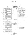
- a mobile terminal 100 includes a wireless communication unit 110, an A/V (audio/video) input unit 120, a user input unit 130, a sensing unit 140, an output unit 150, a memory unit 160, an interface unit 170, a controller 180, and a power supply unit 190.
- FIG. 1 shows the mobile terminal 100 having various components, but it is understood that implementing all of the illustrated components is not a requirement. Greater or fewer components may alternatively be implemented.
- FIG. 1 shows a wireless communication unit 110 configured with several commonly implemented components.
- the wireless communication unit 110 typically includes one or more components that permit wireless communication between the mobile terminal 100 and a wireless communication system or network within which the mobile terminal is located.
- the wireless communication unit 110 can include a broadcast receiving module 111, a mobile communication module 112, a wireless Internet module 113, a short-range communication module 114, and a position-location module 115. At least two broadcast receiving modules 111 can be provided to facilitate simultaneous reception of at least two broadcast channels or broadcast channel switching.
- the broadcast receiving module 111 receives a broadcast signal and/or broadcast associated information from an external broadcast managing server via a broadcast channel.
- the broadcast channel may include a satellite channel or a terrestrial channel.
- the broadcast managing server refers generally to a system that transmits a broadcast signal and/or broadcast associated information or a server which is provided with a previously generated broadcast signal and/or broadcast associated information.
- the broadcast messaging server then transmits the provided signal or information to a terminal.
- broadcast associated information examples include information associated with a broadcast channel, a broadcast program, and a broadcast service provider.
- the broadcast associated information may include an electronic program guide (EPG) of digital multimedia broadcasting (DMB) and electronic service guide (ESG) of digital video broadcast-handheld (DVB-H).
- EPG electronic program guide
- ESG electronic service guide
- the broadcast signal may be implemented as a TV broadcast signal, a radio broadcast signal, or a data broadcast signal.
- the broadcast signal may further include a broadcast signal combined with a TV or radio broadcast signal.
- the broadcast receiving module 111 may be configured to receive broadcast signals transmitted from various types of broadcast systems.
- broadcasting systems include digital multimedia broadcasting-terrestrial (DMB-T), digital multimedia broadcasting-satellite (DMB-S), digital video broadcast-handheld (DVB-H), DVB-CBMS, OMA-BCAST, the data broadcasting system known as media forward link only (MediaFLO®) and integrated services digital broadcast-terrestrial (ISDB-T).
- DMB-T digital multimedia broadcasting-terrestrial
- DMB-S digital multimedia broadcasting-satellite
- DVD-H digital video broadcast-handheld
- DVB-CBMS digital video broadcast-handheld
- OMA-BCAST OMA-BCAST
- MediaFLO® media forward link only
- ISDB-T integrated services digital broadcast-terrestrial
- Receiving multicast signals is also possible.
- Data received by the broadcast receiving module 111 may be stored in a suitable device, such as the memory unit 160.
- the mobile communication module 112 communicates wireless signals with one or more network entities, such as base station or Node-B.
- Such signals may represent, for example, audio, video, multimedia, control signaling, or data.
- the wireless Internet module 113 supports Internet access for the mobile terminal 100.
- the wireless Internet module 113 may be internally or externally coupled to the mobile terminal 100.
- the wireless Internet technology can include, for example, WLAN (Wireless LAN) (Wi-Fi), Wibro (Wireless broadband), Wimax (World Interoperability for Microwave Access), or HSDPA (High Speed Downlink Packet Access).
- the short-range communication module 114 facilitates relatively short-range communications.
- Suitable technologies for short-range communication may include, but are not limited to, radio frequency identification (RFID), infrared data association (IrDA), ultra-wideband (UWB), as well at the networking technologies commonly referred to as Bluetooth® and ZigBee®.
- RFID radio frequency identification
- IrDA infrared data association
- UWB ultra-wideband
- the position-location module 115 identifies or otherwise obtains the location of the mobile terminal 100.
- the position-location module 115 may be implemented using a global positioning system (GPS) module.
- GPS global positioning system
- the audio/video (A/V) input unit 120 is configured to provide audio or video signal input to the mobile terminal 100.
- the AN input unit 120 includes a camera 121 and a microphone 122.
- the camera 121 receives and processes image frames of still pictures or video, which are obtained by an image sensor in a video call mode or a photographing mode.
- the processed image frames can be displayed on the display unit 151.
- the image frames processed by the camera 121 can be stored in the memory unit 160 or can be externally transmitted via the wireless communication unit 110.
- the microphone 122 receives an external audio signal while the mobile terminal 100 is in a particular mode, such as phone call mode, recording mode or voice recognition mode. This audio signal is processed and converted into digital data. The processed audio data is transformed into a format transmittable to a mobile communication base station via the mobile communication module 112 in a call mode.
- the microphone 122 typically includes assorted noise removing algorithms to remove noise generated in the course of receiving the external audio signal.
- Data generated by the A/V input unit 120 may be stored in the memory unit 160, utilized by the output unit 150, or transmitted via one or more modules of the wireless communication unit 110. If desired, two or more cameras 121 or microphones 122 may be provided.
- the user input unit 130 generates input data responsive to user manipulation of an associated input device or devices.
- Examples of such devices include a keypad, a dome switch, a touchpad such as static pressure/capacitance, a jog wheel and a jog switch.
- the sensing unit 140 provides status measurements of various aspects of the mobile terminal 100.
- the sensing unit 140 may detect an open/close status of the mobile terminal 100, the relative positioning of components such as a display and keypad, a change of position of the mobile terminal or a component of the mobile terminal, a presence or absence of user contact with the mobile terminal, or orientation or acceleration/deceleration of the mobile terminal.
- the sensing unit 140 can include a proximity sensor 141.
- the mobile terminal 100 may be configured as a slide-type mobile terminal and the sensing unit 140 may sense whether a sliding portion of the mobile terminal is open or closed.
- the sensing unit 140 may also sense the presence or absence of power provided by the power supply unit 190 or the presence or absence of a coupling or other connection between the interface unit 170 and an external device.
- the output unit 150 generates outputs relevant to the senses such as sight, hearing, and touch.
- the output unit 150 is illustrated in FIG. 1 as having a display unit 151, an audio output module 152, an alarm unit 153, and a haptic module 154.
- the display unit 151 is typically implemented to visually display (output) information associated with the mobile terminal 100. For example, if the mobile terminal 100 is operating in a phone call mode, the display unit 151 will generally provide a user interface (UI) or graphical user interface (GUI) that includes information associated with placing, conducting, and terminating a phone call. If the mobile terminal 100 is in a video call mode or a photographing mode, the display unit 151 may additionally or alternatively display images which are associated with these modes, the UI or the GUI.
- UI user interface
- GUI graphical user interface
- One particular implementation of the present invention includes the display unit 151 configured as a touch screen working in cooperation with an input device, such as a touchpad. This configuration permits the display unit 151 to function both as an output device and an input device.
- the display unit 151 may be implemented using known display technologies including a liquid crystal display (LCD), a thin film transistor-liquid crystal display (TFT-LCD), an organic light-emitting diode display (OLED), a flexible display and a three-dimensional display.
- the mobile terminal 100 may include one or more display unit 151.
- Some of the display units 151 can be implemented as a transparent or optical transmittive type, which can be called a transparent display.
- the transparent display may be a TOLED (transparent OLED).
- a rear configuration of the display 151 unit can be implemented as an optical transmittive type as well. In this configuration, a user is able to see an object at the rear of the terminal body via the area occupied by the display unit 151.
- At least two display units 151 can be provided in accordance with the implemented configuration of the mobile terminal 100.
- a plurality of display units 151 can be arranged on a single face of the mobile terminal 100 such that they are spaced apart from each other or built in one body.
- a plurality of display units 151 can be arranged on different faces of the mobile terminal 100.
- the touch sensor can be configured as a touch film, a touch sheet, or a touchpad.
- the touch sensor can be configured to convert a pressure applied to a specific portion of the display unit 151 or a variation of a capacitance generated from a specific portion of the display unit into an electric input signal.
- the touch sensor may be configured to detect a pressure of a touch as well as a touched position or size.
- a touch input is made to the touch sensor, signal(s) corresponding to the touch are transferred to a touch controller (not shown).
- the touch controller processes the signal(s) and then transfers the processed signal(s) to the controller 180.
- the controller 180 is able to determine whether a specific portion of the display unit 151 is touched.
- the proximity sensor 141 can be provided at an internal area of the mobile terminal 100 enclosed by the touch screen or around the touch screen.
- the proximity sensor 141 is a sensor that detects a presence or non-presence of an object approaching a specific detecting surface or an object existing around the proximity sensor using an electromagnetic field strength or infrared ray without mechanical contact. Therefore, the proximity sensor 141 is more durable than a contact type sensor and also provides wider utility than a contact type sensor.
- the proximity sensor 141 may include a transmittive photoelectric sensor, a direct reflective photoelectric sensor, a mirror reflective photoelectric sensor, a radio frequency oscillation proximity sensor, an electrostatic capacity proximity sensor, a magnetic proximity sensor, an infrared proximity sensor or similar sensors. If the touch screen includes an electrostatic capacity proximity sensor, it is configured to detect the proximity of a pointer using a variation of electric field according to the proximity of the pointer. In this case, the touch screen (touch sensor) can be classified as the proximity sensor 141.
- a 'proximity touch' an action where a pointer that approaches without contacting the touch screen is recognized as located on the touch screen. Furthermore, an action where a pointer actually touches the touch screen is called a 'contact touch'.
- the meaning of a position on the touch screen proximity-touched by the pointer is a position of the pointer that vertically opposes the touch screen when the pointer performs the proximity touch.
- the proximity sensor 141 detects a proximity touch and a proximity touch pattern (e.g., a proximity touch distance, a proximity touch duration, a proximity touch position, or a proximity touch shift state). Information corresponding to the detected proximity touch and the detected proximity touch pattern can be output to the touch screen.
- a proximity touch pattern e.g., a proximity touch distance, a proximity touch duration, a proximity touch position, or a proximity touch shift state.
- the audio output module 152 supports the audio output requirements of the mobile terminal 100.
- the audio output module 152 may be implemented using one or more speakers, buzzers, other audio producing devices, or combinations thereof.
- the audio output module 152 functions in various modes such as call-receiving mode, call-placing mode, recording mode, voice recognition mode and broadcast reception mode.
- the audio output module 152 outputs audio relating to a particular function or status, such as call received, message received, or errors.
- the alarm unit 153 may signal or otherwise identify the occurrence of a particular event associated with the mobile terminal 100. Typical events include call received, message received and user input received.
- the alarm unit 153 outputs a signal for announcing the event occurrence via vibration as well as via video or audio signal.
- the video or audio signal can be output via the display unit 151 or the audio output unit 152. Therefore, the display unit 151 or the audio output module 152 can be regarded as a part of the alarm unit 153.
- the haptic module 154 generates various tactile effects that can be sensed by a user. Vibration is a representative one of the tactile effects generated by the haptic module 154. Strength and pattern of the vibration generated by the haptic module 154 are controllable. For example, different vibrations may be output by being synthesized together or may be output in sequence.
- the haptic module 154 is able to generate various tactile effects as well as vibration.
- the haptic module 154 may generate the effect of an arrangement of pins vertically moving against a contact skin surface, the effect of an injection/suction power of air though an injection/suction hole, the effect of skimming over a skin surface, the effect of contact with an electrode, the effect of electrostatic force, or the effect of hot/cold using an endothermic or exothermic device.
- the haptic module 154 can be implemented to enable a user to sense the tactile effect through a muscle sense of a finger, an arm or other body part as well as to transfer the tactile effect through a direct contact. At least two haptic modules 154 can be provided in the mobile terminal 100 in accordance with the corresponding configuration of the mobile terminal.
- the memory unit 160 is generally used to store various types of data to support the processing, control, and storage requirements of the mobile terminal 100. Examples of such data include program instructions for applications operating in the mobile terminal 100, contact data, phonebook data, messages, pictures, and video.
- a recent use history or a cumulative use frequency of each data (e.g., use frequency for each phonebook, each message or each multimedia) can be stored in the memory unit 160.
- data for various patterns of vibration and/or sound output in case of a touch input to the touchscreen can be stored in the memory unit 160.
- the memory unit 160 may be implemented using any type or combination of suitable volatile and non-volatile memory or storage devices. Examples of memory types are random access memory (RAM), static random access memory (SRAM), electrically erasable programmable read-only memory (EEPROM), erasable programmable read-only memory (EPROM), programmable read-only memory (PROM), read-only memory (ROM), magnetic memory, flash memory, magnetic or optical disk memory, multimedia card micro type memory, card-type memory (e.g., SD memory, XD memory), and other similar memory or data storage devices.
- RAM random access memory
- SRAM static random access memory
- EEPROM electrically erasable programmable read-only memory
- EPROM erasable programmable read-only memory
- PROM programmable read-only memory
- ROM read-only memory
- magnetic memory flash memory
- flash memory magnetic or optical disk memory
- multimedia card micro type memory e.g., SD memory, XD memory
- multimedia card micro type memory e.g.,
- the interface unit 170 is often implemented to couple the mobile terminal 100 with external devices.
- the interface unit 170 receives data from the external devices or is supplied with power and then transfers the data or power to the respective elements of the mobile terminal 100 or enables data within the mobile terminal 100 to be transferred to the external devices.
- the interface unit 170 may be configured using a wired/wireless headset port, an external charger port, a wired/wireless data port, a memory card port, a port for coupling to a device having an identity module, audio input/output ports, video input/output ports, or an earphone port.
- the identity module is a chip for storing various kinds of information for authenticating a user's authority to use the mobile terminal 100 and can include a User Identify Module (UIM), a Subscriber Identity Module (SIM), or a Universal Subscriber Identity Module (USIM).
- a device having the identity module (hereinafter called 'identity device') can be manufactured as a smart card. Therefore, the identity device is connectible to the mobile terminal 100 via a corresponding port.
- the interface unit 170 When the mobile terminal 110 is connected to an external cradle, the interface unit 170 provides a passage for supplying the mobile terminal 100 with power from the cradle or a passage for delivering various command signals to the mobile terminal 100 that are input from the cradle by a user.
- Each of the various command signals input from the cradle or the power can operate as a signal enabling the mobile terminal 100 to determine that it is correctly loaded in the cradle.
- the controller 180 typically controls the overall operations of the mobile terminal 100. For example, the controller 180 performs the control and processing associated with voice calls, data communications, instant message communication, video calls, camera operations and recording operations. Furthermore, the controller 180 may perform a pattern recognizing process for recognizing a writing input and a picture drawing input performed on the touch screen as characters or images.
- the controller 180 may include a multimedia module 181 that provides multimedia playback.
- the multimedia module 181 may be configured as part of the controller 180 or implemented as a separate component.
- the power supply unit 190 provides power required by the various components for the mobile terminal 100.
- the power may be internal power, external power, or combinations thereof.
- embodiments described herein may be implemented in various ways.
- the embodiments may be implemented in a computer-readable medium using computer software, hardware, or some combination thereof.
- the embodiments described may be implemented within one or more application specific integrated circuits (ASICs), digital signal processors (DSPs), digital signal processing devices (DSPDs), programmable logic devices (PLDs), field programmable gate arrays (FPGAs), processors, controllers, micro-controllers, microprocessors, other electronic units designed to perform the functions described herein, or a combination of these devices.
- ASICs application specific integrated circuits
- DSPs digital signal processors
- DSPDs digital signal processing devices
- PLDs programmable logic devices
- FPGAs field programmable gate arrays
- processors controllers, micro-controllers, microprocessors, other electronic units designed to perform the functions described herein, or a combination of these devices.
- the controller 180 may also implement such embodiments.
- the embodiments described herein may be implemented with separate software modules, such as procedures and functions, each of which perform one or more of the functions and operations described herein.
- the software codes can be implemented with a software application written in any suitable programming language and may be stored in memory, such as the memory unit 160, and executed by a controller or processor, such as the controller 180.
- FIG. 2A is a front perspective diagram of a mobile terminal according to one embodiment of the present invention.
- FIG. 2B is a perspective diagram of a backside of the terminal shown in FIG. 2A .
- the mobile terminal 100 illustrated in FIGS. 2A and 2B has a bar type terminal body.
- the mobile terminal 100 may be implemented in a variety of different configurations. Examples of such configurations include folder-type, slide-type, rotational-type, swing-type and combinations thereof. For clarity, further disclosure will primarily relate to a bar-type mobile terminal 100. However such teachings apply equally to other types of mobile terminals.
- the mobile terminal 100 includes a case (casing, housing, cover, etc.) configuring an exterior of the mobile terminal.
- the case can be divided into a front case 101 and a rear 102 case.
- Various electric/electronic parts are located in a space between the front 101 and rear 102 cases.
- at least one middle case can be provided between the front 101 and rear 102 cases.
- the cases 101 and 102 may be formed by injection molding synthetic resin.
- the cases 101 and 102 may also be formed of a metal substance such as stainless steel (STS) or titanium (Ti).
- STS stainless steel
- Ti titanium
- the display 151, audio output unit 152, camera 121, manipulating units 130a and 130b, microphone 122, and interface unit 170 can be provided on the terminal body, specifically on the front case 101.
- the display 151 occupies most of a main face of the front case 101.
- the audio output unit 152 and the camera 121 are provided on an area adjacent to one of the end portions of the display 151, while one manipulating input unit 130a and the microphone 122 are provided on another area adjacent to the other end portion of the display.
- the other manipulating unit 130b and the interface unit 170 can be provided on lateral sides of the front and rear cases 101 and 102.
- the input unit 130 is manipulated to input a command for controlling an operation of the terminal 100 and may include the manipulating units 130a and 130b.
- the manipulating units 130a and 130b can be called a manipulating portion and may adopt any mechanism having a tactile manner that enables a user to perform a manipulation action by experiencing a tactile feeling.
- Content input via the first or second manipulating unit 130a or 130b can be diversely set.
- a command such as start, end, or scroll is input via the first manipulating unit 130a and a command for a volume adjustment of sound output from the audio output unit 152 or a command for switching to a touch recognizing mode of the display 151 can be input via the second manipulating unit 130b.
- an additional camera 121' can be provided on a rear side of the terminal body, specifically on the rear case 102.
- the camera 121' has a photographing direction that is substantially opposite to that of the camera 121 illustrated in FIG. 2A and may have pixels differing from those of the camera 121.
- the camera 121 illustrated in FIG. 2A has pixels low enough to capture and transmit a picture of user's face for a video call, while the camera 121' has high pixels for capturing a general subject for photography without transmitting the captured subject.
- Each of the cameras 121 and 121' can be installed such that they can be rotated or popped up.
- a flash 123 and a mirror 124 are additionally provided adjacent to the camera 121'.
- the flash 123 projects light toward a subject for photographing the subject using the camera 121'. If user attempts to take a self-photography using the camera 121', the mirror 124 enables the user to view his or her face reflected by the mirror 124.
- An additional audio output unit 152' can be provided on the rear side of the terminal body.
- the additional audio output unit 152' may implement a stereo function together with the audio output unit 152 illustrated in FIG. 2A and may be used for implementation of a speakerphone mode while talking.
- a broadcast signal receiving antenna 124 can be provided on the lateral side of the terminal body as well as an antenna for communication.
- the antenna 124 comprising a portion of the broadcast receiving module 111 illustrated in FIG. 1 can be retractably provided on the terminal body.
- a power supply unit 190 for supplying power to the mobile terminal 100 is provided.
- the power supply unit 190 can be configured to be located within the terminal body.
- the power supply unit 190 can be configured to be detachably connected to the terminal body.
- the manipulation unit 130 is referred to as an "input device 200" in the following description.
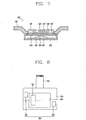
- FIG. 3 is a cross-sectional view illustrating an input device 200 according to an embodiment of the present invention.
- FIG. 4 is a plan view illustrating a printed circuit board illustrated in FIG. 3 .
- the input device 200 may include a key button 210, an illumination sensor 220, and a light-emitting portion 230.
- the key button 210 is formed of a transparent material, which has an internal space for mounting the illumination sensor 220 and the light-emitting portion 230.
- the transparent material of the key button 210 allows a light signal emitted from the light-emitting portion 230 and external light signals to pass through.
- Transparency is a concept including full-transparency or semi-transparency, and the key button 210 may be formed of a transparent plastic material, or other similar material.
- FIGS. 3 and 4 illustrate that an overall region of the key button 210 is formed of a transparent material. It is also possible that a partial region of the key button 210 is formed of a transparent material and the remaining region is formed of a non-transparent material.
- the key button 210 may have a structure that is fixed to the front case 101 or to a printed circuit board (PCB) 240.
- PCB printed circuit board
- the illumination sensor 220 is located in an internal space of the key button 210 to sense ambient illumination of the terminal body or key button.
- the illumination sensor 220 receives a light signal having a particular wavelength bandwidth, such as visible rays, and senses illumination based on the particular wavelength.
- the illumination sensor 220 may include a light-receiving portion 221 for receiving the light signal.
- the light-emitting portion 230 is located in an internal space of the key button 210 and at a side of the illumination sensor 220.
- the light-emitting portion 230 outputs a light signal for detecting a touch applied to the key button 210.
- the light signal output by the light-emitting portion 230 has a particular wavelength bandwidth, such as a bandwidth that is different from the wavelength bandwidth for sensing illumination, and is output to the outside through the key button 210.
- Examples of the light-emitting portion 230 may include an infrared-emitting module for outputting infrared rays.
- an infrared-emitting module for outputting infrared rays.
- a touch is applied to the key button 210, a light signal (infrared rays) output from the light-emitting portion 230 is reflected by the user's finger, and the reflected light signal (infrared rays) is input to the light-receiving portion 221 of the illumination sensor 220.
- the arrow in FIG. 3 indicates a traveling direction of the light signal output from the light-emitting portion 230.
- the light-receiving portion 221 of the illumination sensor 220 receives a light signal having a first bandwidth (visible rays) for sensing illumination.
- the light receiving portion 221 is configured to receive a light signal having a second bandwidth (infrared rays) for detecting a touch applied to the key button 210.
- the illumination sensor 220 and light-emitting portion 230 may be mounted on the PCB 240.
- the PCB 240 may be formed a rigid substrate.
- the PCB 240 may be supported by a supporting portion 105 formed on the front case 101 and may be electrically connected to a main board inside the terminal body by a flexible printed circuit board (FPCB) 245.
- FPCB flexible printed circuit board
- a spacer 247 with an elastically deformable material may be additionally provided between the illumination sensor 220 and an internal wall of the key button 210.
- the spacer 247 is provided to suppress shock generated when a touch is applied to the key button 210 from being directly transferred to the illumination sensor 220 and may be formed of a rubber or silicon material.
- the spacer 247 is formed with a through hole 248 for inputting a light signal to the light-receiving portion 221.
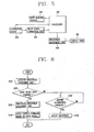
- FIG. 5 is a block diagram illustrating a configuration of an input device according to an embodiment of the present invention.
- the illumination sensor 220 is connected to an input signal generation unit 250.
- the input signal generation unit 250 generates a touch input signal when a light signal (infrared rays) output from the light-emitting portion 230 is input to the light-receiving portion 221 of the illumination sensor 220.
- the illumination sensor 220, light-emitting portion 230, and input signal generation unit 250 may be electrically connected to the controller 180 of the mobile terminal 100. It is also possible to have a configuration where the input signal generation unit 250 is included in the controller 180.
- the controller 180 controls the operation of the light-emitting portion 230, for example, whether or not the light signal is output.
- the controller 180 also receives a touch input signal generated from the input signal generation unit 250 and applies a control command to components mounted on the terminal body based on the touch input signal. Moreover, the controller 180 applies a control command to components mounted on the terminal body using illumination sensing data supplied from the illumination sensor 220.
- Examples of the mounted components may include a display unit 151.
- the mobile terminal 100 may further include a brightness adjustment unit 260 for adjusting the brightness of the display unit 151 based on the sensing result of the illumination sensor 220.
- the brightness adjustment unit 260 adjusts the brightness of the display unit 151 according to ambient illumination. This is facilitated by adjusting a lighting unit for illuminating the display unit 151 or by adjusting an amount of light emitted by the display unit if the display unit emits light spontaneously.
- the brightness adjustment unit 260 adjusts the brightness of the display unit 151 to a higher level as ambient illumination becomes brighter. In other words, the brightness adjustment unit 260 adjusts the brightness of the display unit 151 such that the brightness of the display unit 151 is proportional to ambient illumination.
- FIG. 5 illustrates the brightness adjustment unit 260 separated from the controller 180. It is also possible that the brightness adjustment unit 260 is included in the controller 180.
- FIG. 6 is a flow chart illustrating a method of a brightness adjustment unit and an input device according to an embodiment of the present invention.
- the controller 180 activates the brightness adjustment unit 260 (S110). It is possible to set the brightness adjustment unit 260 to maintain an activated state until receiving another control command.
- the controller 180 determines whether an amount of the light signal (infrared) data received by the light-receiving portion 221 of the illumination sensor 220 changes (S120). Then, the controller 180 controls activation or deactivation of the brightness adjustment unit 260 based on the determination.
- a determination that the amount of the light signal (infrared) data changes or a light signal is received by the light-receiving portion 221 means that a touch is applied to the key button 210 and a light signal (infrared rays) is received by the light-receiving portion. If it is determined that the amount of the light signal (infrared) data changes, the controller 180 deactivates the brightness adjustment unit 260 (S130), thereby making it possible to prevent the brightness of the display unit 151 from being adjusted by an illumination change caused by the user's finger covering the key button 210. When the brightness adjustment unit 260 is deactivated, the controller 180 applies a control command to mounted components based on an input signal generated from the input signal generation unit 250 (S140).
- the brightness adjustment unit 260 determines a change of ambient illumination (S150) and adjusts the brightness of the display unit 151 on the basis of the determination (S160).
- the present invention allows the illumination sensor 220 to be provided inside the key button 210 and, therefore, it is not required that a separate mounting space be provided for mounting the illumination sensor on the terminal body. Accordingly, it may be possible to enhance the spatial utility of the mobile terminal 100 and provide a new touch input structure using the illumination sensor 220 applied to the input device 200.
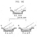
- FIG. 7 is a cross-sectional view illustrating an input device according to another embodiment of the present invention and FIG. 8 is a plan view illustrating a printed circuit board illustrated in FIG. 7 .
- FIGS. 7 and 8 the same construction as in the previous embodiment is designated by the same reference numerals and their description will be replaced by the previous description.
- an input device 300 may include a key button 310, an illumination sensor 320, and a light-emitting portion 330.
- the illumination sensor 320 is connected to an input signal generation unit 250 and the illumination sensor, light-emitting portion 330, and input signal generation unit are connected to the controller 180.
- the input device 300 may further include a dome switch 341 in addition to the other elements.
- the embodiment illustrated in FIGS. 7 and 8 is of a key button 310 that is fixed to a printed circuit board 340 such that it can be moved in an inward direction of the terminal body.
- the dome switch 341 is formed on a dome sheet 342 in order to generate an input signal according to pressing the key button 310.
- the dome sheet 342 is supported by a supporting portion 107 formed on the front case 101.
- the printed circuit board 340 is formed with a push protrusion 343, which presses the dome switch 341 in response to pressing the key button 310. Accordingly, the dome switch 341 is deformed to be connected to a contact point of the dome sheet 342, thereby generating a push input signal.
- the input device 300 of the embodiment illustrated in FIGS. 7 and 8 allows an input method mixed with a method of touching the key button 310 and a method of clicking the illumination sensor 320 to be applied.
- the controller 180 applies a control command to components mounted on the terminal body based on a touch input signal generated by the input signal generation unit 250 and a push input signal generated by the dome sheet 342.
- the embodiment illustrated in FIGS. 7 and 8 further includes a first light-emitting portion 331 and a second light-emitting portion 332 as part of light-emitting portion 330.
- the first and second light-emitting portions 331, 332 may be mounted on both sides of the illumination sensor 320.
- the first and second light-emitting portions 331, 332 are provided to allow the input device 300 to detect a slide touch applied to the key button 310 in at least one direction.
- the slide touch is an input by sliding the user's finger while in contact with the key button 310.
- the first light-emitting portion 331 and second light-emitting portion 332 may be located at asymmetric positions with respect to the center of the light-receiving portion 321 in order to differentiate an amount of the light signal (infrared rays) data input to the light-receiving portion 321 according to a starting point of the user's finger at the time of the slide touch.
- the slide touch can be differentiated between starting from the right region of the key button 310 and traveling toward the left region and starting from the left region of the key button and traveling toward the right region.
- the input signal generation unit 250 generates a touch input signal based on a changed amount of the light signal (infrared rays) data received at the light-receiving portion 321.
- the input signal generation unit 250 also generates a different touch input signal according to a direction of the slide touch based on the starting point of the slide touch.
- FIGS. 7 and 8 has a dome switch 341 added to the previous embodiment as well as the light-emitting portion 330 implemented with first and second light-emitting portions 331, 332.
- an input device of the present invention may have all the elements added or some of the elements may be selectively applied.
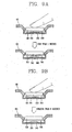
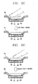
- FIGS. 9A through 9E are views illustrating examples of an input method using the input device illustrated in FIG. 7 .
- a variety of input methods can be implemented by using a touch input and a push input. It is possible to set the controller 180 to generate a different control command according to a duration time of the push input and touch input or a direction of the slide touch.
- FIGS. 9A and 9B illustrate a push input method using a dome switch 341. As illustrated in FIGS. 9A and 9B , the push input can be classified into two types of input methods according to the duration time.
- a duration time of the push input that is set within a predetermined period of time may be differentiated from a duration time of the push input that is set above a predetermined period of time, such as 2 seconds as illustrated in FIG. 9B .
- the situation illustrated in FIG. 9A is designated as a short click and the situation illustrated in FIG. 9B is designated as a long click.
- FIGS. 9C and 9D illustrate an input method through a touch input. Two types of input methods are illustrated according to a duration time of the touch input.
- the touch input may be classified into a slide touch, as illustrated in FIG. 9C , and a long touch, as illustrated in FIG. 9D .
- the input signal generation unit 250 generates a different input signal according to a duration time of the touch input, specifically, a duration time of the light signal (infrared) data.
- FIG. 9C illustrates a slide touch made within a predetermined period of time, such as 1 second.
- FIG. 9C illustrates that the slide touch is made from the right region of the key button 310 toward the left region of the key button, or vice-versa.
- FIG. 9D illustrates a touch input applied for longer than a predetermined period of time, such as 2 seconds.
- FIG. 9E illustrates a method of sequentially inputting a short click and a slide touch, an input method referred to as a "click-slide touch.”
- a sequential push-and-touch input or sequential touch-and-push input may be modified in a various forms in addition to the click-slide touch illustrated in FIG. 9F .
- a method of inputting via an input device may include five types of input methods, such as a short click, a long click, a slide touch, a long touch, and a click-slide touch.
- the controller 180 may apply a different control command for each of the touch inputs (slide touch or long touch), the push inputs (short click or long click), and the sequential push-and-touch input (click-slide touch).
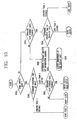
- FIG. 10 is a flow chart illustrating a method of generating an input signal in a mobile terminal 100 according to the present invention.
- the controller 180 sequentially determines an existence or non-existence of a push input, a changed amount of infrared data, and a changed amount of visible rays data.
- the controller 180 determines the existence or non-existence of the input (push input) via a dome switch 341 (S210).
- the controller 180 determines a duration time of the push input (S220). If the duration time of the push input is greater than a predetermined period of time, such as 1 second, the controller 180 determines that a long click has been received. If the duration time of the push input is less than a predetermined period of time, such as 1 second, the controller 180 or input signal generation unit 250 determines a changed amount of the light signal (infrared) data input to a light-receiving portion 321 of the illumination sensor 320 (S230).
- the controller 180 determines that a short click has been received. If there is a change in the amount of infrared data, the controller 180 determines that a click-slide touch has been received.
- the controller 180 or input signal generation unit 250 determines a changed amount of the light signal (infrared) data input to a light-receiving portion 321 of the illumination sensor 320 (S240).
- the controller 180 or input signal generation unit 250 determines a duration of the infrared data (S250). If the duration of the infrared data is less than a predetermined period of time, such as 1 second, the controller 180 or input signal generation unit 250 determinates that a slide touch has been received. If the duration of the infrared data is greater than a predetermined period of time, such as 2 seconds, the controller 180 or input signal generation unit 250 determinates that a long touch has been received.
- the controller 180 determines the illumination sensing data of the illumination sensor 220 (S260). If there is a change in the illumination sensing data, the controller 180 allows the brightness adjustment unit 260 to adjust the brightness of the display unit 151 according to the change. The adjustment of the brightness of the display unit 151 replaces the process of activating or deactivating the brightness adjustment unit 260 according the previous description.
- the operation of a mobile terminal 100 may be controlled in a variety of operation modes using an input device having various input methods.
- the controller 180 can apply a control command to the display unit 151 in order to control the screen display of the display unit according to the previously described push input and touch input.
- the control command may include at least a command for restoring a preset screen during the execution of a specific mode, a command for executing a selected operation, a command for displaying upper-level items of the currently-executed function, a command for displaying a menu, a command for switching to a next or previous page, a command for moving a cursor or pointer, a command for scrolling a screen in a specific direction, or a zoom-in or zoom-out command.
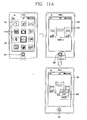
- FIGS. 11A through 11C are views illustrating examples of an input method via an input device in a text view mode according to the present invention.
- a plurality of icons 411 are displayed on the display unit 151.
- the icons 411 indicate various operation modes and applications provided by a mobile terminal 100. The user selects one of those icons 411 to implement an operation mode or application.
- display unit 151 is a touch screen
- one of the icons 411 can be selected by directly touching it. It is also possible to select one of the icons 411 using the input device 300.
- a pointer 412 may be displayed on one of the icons 411 and the pointer 412 may be moved by using an input device 300.
- the pointer 412 may be moved in a desired direction by applying a slide touch in the left or right direction to the key button 310.
- text files 413 stored in the mobile terminal 100 can be displayed as icons on the display unit 151.
- FIG. 11A illustrates a slide touch applied to the key button 310 in the left or right direction in order to move the displayed text files 413 in the desired direction, where a text file displayed in the center is a currently selected file.
- a pointer may also be displayed on any one of the text files 413 to indicate a currently selected file.
- a click-right slide touch is applied to display a menu 414 for the selected text file 413.
- Commands such as cut, copy and paste for editing the text file 413 may be displayed on the menu 414.
- the pointer displayed on the commands may be moved by a slide touch and the selected command may be implemented by a short click.
- the click-slide touch may be used as a menu display command or menu display release command according to a direction of the slide touch.
- FIG. 11B illustrates that any one of the text files 413 may be selected and implemented.
- the contents of the selected file are displayed as text.
- the display unit 151 displays a particular page
- the displayed page may be switched by applying a slide touch to the key button 310. For example, a next page 416 is displayed on the display unit 151 when a left-directional slide touch is applied and a previous page 417 is displayed on the display unit when a right-directional slide touch is applied.
- FIG. 11C illustrates a process of restoring an execution screen of the operation mode to a predetermined screen using an input device.
- an execution screen 418 in a text view mode can be restored to a menu view screen 419 on which icons 411 are displayed by applying a long click to the key button 310.
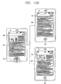
- FIGS. 12A through 12E illustrate an input method through an input device in an image view mode.
- FIG. 12A illustrates a screen on which an image photo view mode is implemented. Any one image 421 of images stored in a mobile terminal 100 is displayed on the display unit 151. A next or previous image 422 may be displayed by applying a slide touch to the key button 310.
- FIG. 12B illustrates a process of zooming an image in or out using the input device. If a long touch is applied to the key button 310 while executing an image view mode, icons 423, 424 for selecting a zoom in/out mode or screen scroll mode are displayed. The zoom in/out mode or screen scroll mode is selected by applying a short click to the key button 310. A pointer for displaying a currently selected mode may be displayed on either of the icons 423, 424.
- FIG. 12B illustrates a zoom in/out mode by which a screen can be enlarged or reduced by applying a slide touch to the key button 310.
- a screen can be enlarged or reduced by applying a slide touch to the key button 310.
- an enlarged screen 426 is displayed when a slide touch is applied in the right direction.
- the screen can also be reduced when a slide touch is applied in the left direction.
- FIG. 12C illustrates a process of scrolling a screen in a screen scroll mode.
- the zoom in/out mode can be switched to the screen scroll mode by applying a short click to the key button 310. For example, a pointer displayed on the icon 423 displaying a zoom in/out mode is moved to the icon 424 displaying a screen scroll mode in order to switch to the screen scroll mode. A long touch is applied to the key button 310 to release the zoom-in/out mode or screen scroll mode.
- the displayed screen can be scrolled in a left or right direction by applying a slide touch to the key button 310. For example, when a slide touch is applied toward the right direction, as illustrated in FIG. 12C , the displayed screen is moved to the right.
- the displayed screen can be scrolled in an upward or downward direction by applying a click-slide touch to the key button 310. For example, when the key button 310 is clicked and a slide touch is applied in the right direction, as illustrated in FIG. 12C , the displayed screen is moved in a downward direction.
- FIG. 12D illustrates a process of switching from an image view mode to an upper-level of a currently displayed image. As illustrated in FIG. 12D , if a short click is applied to the key button 310, an upper-level of the currently displayed image will be displayed. As a result, all the items 425 in a folder in which the currently displayed image is stored will be displayed.
- FIG. 12E illustrates a process of restoring an execution screen in an image view mode to a predetermined screen. For example, if a long click is applied to the key button 310, an execution screen is restored to a menu display screen on which icons 411 are displayed. The long click functions as a "Home key.”
- FIGS. 13A and 13B are views illustrating examples of an input method via an input device in a web-browsing mode.
- the input methods illustrated in FIGS. 12B through 12E for scaling or scrolling a screen may be applicable to a web browsing mode in a similar manner.
- a web browsing screen 431 is displayed on the display unit 151 in a web browsing mode.
- the web browsing screen can be scrolled in a left or right direction by applying a slide touch to the key button 310. For example, when a slide touch is applied to the key button 310 in the left direction, the web browsing screen is moved to the left direction and regions that have not been previously displayed will be displayed.
- the displayed screen can be scrolled in an upward or downward direction by applying a click-slide touch to the key button 310.
- a click-slide touch For example, when the key button 310 is clicked and a slide touch is applied in the left direction, as illustrated in FIG. 13B , the displayed screen is moved in an upward direction.
- FIG. 14 is a perspective view illustrating a mobile terminal 100 according to another embodiment of the present invention.
- the mobile terminal 100 may include first and second bodies 510, 520 combined with each other in a relatively movable manner.
- a slide type terminal is illustrated in which the first body 510 is slidably combined with the second body 520.
- the mobile terminal 100 may also have a different form, such as folder type or swing type.
- a display unit 151, a camera 121, a speaker 152, a first manipulation unit 131, and a microphone 122 may be located on the first body 510.
- the previously described input devices 200, 300 may be applied to the first manipulation unit 131.
- Second and third manipulation units 132, 133, and an interface unit 170 may be located on the second body 520.
- the second body 520 may be moved from a closed configuration, in which a portion of the second body is hidden, to an open configuration, in which the hidden portion is exposed.
- a third manipulation unit 133 is mounted on the portion exposed by the movement.
- the third manipulation unit 133 may include key buttons having a QWERTY-type arrangement and key information, such as characters, numerals, and symbols for inputting keys is displayed on the key buttons.
- the previously described input devices 200, 300 may be applicable to portion of the key buttons or all the key buttons.
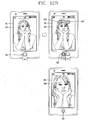
- FIGS. 15 and 16 are views illustrating an operation method of the mobile terminal 100 illustrated in FIG. 14 .
- FIGS. 15 and 16 illustrate an example in which a structure of the previously described input device 300 is only applied to key buttons 133' placed at the most upper column of a plurality of the columns.
- a process is illustrated in which text is deleted in a text editing mode using a slide touch applied to the key buttons 133'.
- the slide touch may be assigned to a text delete command in the text editing mode.
- a text editing screen for transmitting a text message or e-mail is displayed on the display unit 151.
- Text can be entered via a push input to the third manipulation unit 133.
- Entered text is displayed on the display unit 151.
- a left-directional slide touch is applied to a key, such as "P", placed at a right end portion of the key buttons 133' arranged on the upper end
- text placed on the left side of the current cursor is deleted.
- a left-directional slide touch is applied to a predetermined number of keys from the key, such as "P”, placed at a right end portion of the key buttons 133'
- text can be deleted according to the number of text characters corresponding to the number of the slide-touched key buttons.
- four text characters are deleted when a slide touch is applied to four key buttons.
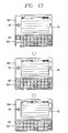
- FIG. 17 is a view illustrating another operation method of the mobile terminal 100 illustrated in FIG. 14 .
- FIG. 17 illustrates an upper/lower-case character conversion method using an input device.
- a plurality of key information may be assigned to at least one of the key buttons of the third manipulation unit 133.
- key information (Shift) for upper/lower-case character conversion as well as key information (Q) for character input may be assigned to a particular key button 133" (Q-button) of the key buttons of the third manipulation unit 133. It is possible that key information (Q) for character input is entered if a short click is applied to the relevant key button 133" and key information (Shift) for upper/lower-case character conversion is entered if a long touch is applied thereto.
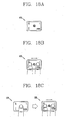
- FIGS. 18A through 18C are views illustrating still another operation method of the mobile terminal 100 illustrated in FIG. 14 .
- a plurality of key information may be displayed on each of the key buttons of the third manipulation unit 133.
- the key information may include different types of information, such as characters, numerals, symbols, and words.
- a plurality of key information are displayed on the key button and at least two of a touch input, push input, and sequential push-and-touch input to those key buttons may be assigned to a plurality of key information displayed on the key button.
- FIGS. 18A through 18C illustrate that five types of key information are displayed on a single key button.
- Key information (q) corresponding to a lower-case character is displayed at the center of the key button and key information (Q) corresponding to an upper-case character is displayed at the top-left side of the key button.
- key information (1) corresponding to a numeral is displayed at the top-right side of the key button.
- key information ([) corresponding to symbol is displayed at the bottom-left side of the key button and key information (.com) corresponding to a frequently used word or phrase is displayed at the bottom-right side of the key button.
- a push input to the key button may be assigned to the key information (q) corresponding to a lower-case character.
- a slide touch to the key button may be assigned to key information (Q, 1) displayed on a top portion of the key button. For example, key information (Q) corresponding to an upper-case character is entered if a left-directional slide touch is applied to the key button and the key information (1) corresponding to a numeral is entered if a right-directional slide touch is applied to the key button.
- a click-slide touch may be assigned to key information ([and .com) displayed on a bottom portion of the key button. For example, key information ([) corresponding to a symbol is entered if the key button is clicked and a left-directional slide touch is applied to the key button, and key information (.com) corresponding to a word or phrase is entered if the key button is clicked and a right-directional slide touch is applied to the key button.
- the number of key buttons can be reduced. This has an advantage of reducing a space of the terminal body on which the input device is mounted.
- an illumination sensor is provided inside a key button and it is not necessary to provide a separate mounting space for mounting the illumination sensor on the terminal body.
- a dome switch is additionally applied to an input device to provide an input device capable of receiving both a touch input and a push input.
- touch and push input methods can be mixed with each other, thereby providing various input methods with a fewer number of key buttons.
- the present invention can take the form of an entirely hardware embodiment, an entirely software embodiment or an embodiment containing both hardware and software elements.
- a software embodiment may include, but not be limited to, to firmware, resident software, microcode, etc.
- the invention can take the form of a computer program product accessible from a computer-usable or computer-readable medium providing program code for use by or in connection with a computer or any instruction execution system.
- a computer-usable or computer readable medium can be any apparatus that can contain, store, communicate, propagate, or transport the program for use by or in connection with the instruction execution system, apparatus, or device.
- a data processing system suitable for storing and/or executing program code will include at least one processor coupled directly or indirectly to memory elements through a system bus.
- the memory elements can include local memory employed during actual execution of the program code, bulk storage, and cache memories which provide temporary storage of at least some program code in order to reduce the number of times code must be retrieved from bulk storage during execution.
- I/O devices including but not limited to keyboards, displays, pointing devices, etc.
- I/O controllers can be coupled to the system either directly or through intervening I/O controllers.
- Network adapters e.g., modem, cable modem, Ethernet cards
- logic code programs, modules, processes, methods, and the order in which the respective elements of each method are performed are purely exemplary. Depending on the implementation, they may be performed in any order or in parallel, unless indicated otherwise in the present disclosure. Further, the logic code is not related, or limited to any particular programming language, and may be comprise one or more modules that execute on one or more processors in a distributed, non-distributed, or multiprocessing environment.
- the method as described above may be used in the fabrication of integrated circuit chips.
- the resulting integrated circuit chips can be distributed by the fabricator in raw wafer form (that is, as a single wafer that has multiple unpackaged chips), as a bare die, or in a packaged form.
- the chip is mounted in a single chip package (such as a plastic carrier, with leads that are affixed to a motherboard or other higher level carrier) or in a multi-chip package (such as a ceramic carrier that has either or both surface interconnections of buried interconnections).
- the chip is then integrated with other chips, discrete circuit elements, and/or other signal processing devices as part of either (a) an intermediate product, such as a motherboard, or (b) and end product.
- the end product can be any product that includes integrated circuit chips, ranging from toys and other low-end applications to advanced computer products having a display, a keyboard or other input device, and a central processor.
Landscapes
- Engineering & Computer Science (AREA)
- Theoretical Computer Science (AREA)
- General Engineering & Computer Science (AREA)
- Human Computer Interaction (AREA)
- Physics & Mathematics (AREA)
- General Physics & Mathematics (AREA)
- Computer Hardware Design (AREA)
- Signal Processing (AREA)
- Telephone Function (AREA)
- Telephone Set Structure (AREA)
- Input From Keyboards Or The Like (AREA)
- Push-Button Switches (AREA)
Claims (14)
- Mobiles Endgerät (100), das aufweist:einen Endgerätkörper; undeine auf dem Endgerätkörper montierte Eingabevorrichtung (200, 300),wobei die Eingabevorrichtung aufweist:wenigstens einen Tastenknopf (210, 310), der aus einem transparenten Material ausgebildet ist und einen Innenraum hat;einen Beleuchtungssensor (220, 320), der in dem Innenraum angeordnet ist und einen lichtempfangenden Abschnitt (221, 321) hat, wobei der Beleuchtungssensor (220, 320) aufgebaut ist, um Umgebungsbeleuchtung des Endgerätkörpers abzutasten;einen lichtemittierenden Abschnitt (230, 330), der an einer Seite des Beleuchtungssensors (220, 320) angeordnet ist und aufgebaut ist, um ein Lichtsignal nach außerhalb des Tastenknopfs (210, 310) auszugeben, um eine Berührung zu erfassen, die auf den wenigstens einen Tastenknopf (210, 310) angewendet wird;eine Eingangssignalerzeugungseinheit (250), die aufgebaut ist, um ein Berührungseingabesignal gemäß der Lichtsignaleingabe in den lichtempfangenen Abschnitt des Beleuchtungssensors (220, 320) zu erzeugen; undeinen Abstandshalter (247) mit einem elastisch verformbaren Material zwischen dem Beleuchtungssensor (220, 320) und einer Innenwand des wenigstens einen Tastenknopfs (210, 210), wobei ein Durchgangsloch (248) an dem Abstandshalter (247) ausgebildet ist, um ein Lichtsignal in den lichtempfangenden Abschnitt (221, 321) des Beleuchtungssensors (220, 320) einzugeben.
- Mobiles Endgerät (100) nach Anspruch 1, wobei der lichtemittierende Abschnitt (230) ein Infrarot-emittierendes Modul ist, das aufgebaut ist, um Infrarotstrahlen zu emittieren.
- Mobiles Endgerät (100) nach Anspruch 1 oder 2, wobei der lichtemittierende Abschnitt (330) einen ersten lichtemittierenden Abschnitt (331), der an einer ersten Seite des Beleuchtungssensors (220, 320) montiert ist, und einen zweiten lichtemittierenden Abschnitt (332), der an einer zweiten Seite des Beleuchtungssensors (2210, 320) montiert ist, aufweist, um eine Gleitberührung zu erfassen, die auf den wenigstens einen Tastenknopf (210, 310) angewendet wird.
- Mobiles Endgerät (100) nach Anspruch 3, wobei die Eingangssignalerzeugungseinheit (250) gemäß der Richtung der Gleitberührung ein unterschiedliches Eingangssignal erzeugt.
- Mobiles Endgerät (100) nach einem der Ansprüche 1 bis 4, das ferner aufweist:eine Anzeigeeinheit (151), die auf dem Endgerätkörper montiert ist und aufgebaut ist, um visuelle Informationen anzuzeigen; undeine Helligkeitseinstelleinheit (260), die aufgebaut ist, um eine Helligkeit der Anzeigeeinheit (151) gemäß der von dem Beleuchtungssensor (220, 320) abgetasteten Umgebungsbeleuchtung einzustellen.
- Mobiles Endgerät (100) nach Anspruch 5, das ferner aufweist:eine Steuerung (180), die aufgebaut ist, um die Aktivierung oder Deaktivierung der Helligkeitseinstelleinheit (260) gemäß einer geänderten Intensität des in den lichtempfangenden Abschnitt (221, 321) des Beleuchtungssensors (220, 320) eingegebenen Lichtsignals zu steuern.
- Mobiles Endgerät (100) nach Anspruch 6, wobei die Steuerung (180) ferner aufgebaut ist, um die Helligkeitseinstelleinheit (260) zu deaktivieren, wenn eine Intensität des Lichtsignals geändert wird, wenn die Helligkeitseinstelleinheit (260) aktiviert wird.
- Mobiles Endgerät (100) nach einem der Ansprüche 1 bis 5, das ferner aufweist:einen gewölbten Schalter (341), der aufgebaut ist, um gemäß dem wenigstens einen gedrückten Tatenknopf (210, 310) ein Druckeingabesignal zu erzeugen; undeine Steuerung (180), die aufgebaut ist, um gemäß dem Berührungseingabesignal und dem Druckeingabesignal einen Steuerbefehl auf Komponenten anzuwenden, die auf dem Endgerätkörper montiert sind.
- Mobiles Endgerät (100) nach Anspruch 8, wobei die Steuerung (180) ferner aufgebaut ist, um für jede einer Berührungseingabe, einer Druckeingabe und einer sequentiellen Druck- und Berührungseingabe einen anderen Steuerbefehl auszugeben.
- Mobiles Endgerät (100) nach Anspruch 9, wobei die Berührungseingabe eine Verschiebungseingabe aufweist, die vorgenommen wird, indem ein Finger auf dem wenigstens einen Tastenknopf (210, 310) gleitet, und die Steuerung (180) ferner aufgebaut ist, um gemäß der Richtung der Gleitberührung einen unterschiedlichen Steuerbefehl anzuwenden.
- Mobiles Endgerät (180) nach Anspruch 9, wobei mehrere Schlüsselinformationen auf dem wenigstens einen Tastenknopf (210, 310) angezeigt werden, und wenigstens zwei der Berührungseingabe, der Druckeingabe und der sequentiellen Druck- und Berührungseingabe einer der mehreren Tasteninformationen zugewiesen sind.
- Mobiles Endgerät (100) nach Anspruch 9, wobei die Steuerung (180) ferner aufgebaut ist, um gemäß einer Zeitdauer wenigstens der Druckeingabe oder der Berührungseingabe einen unterschiedlichen Steuerbefehl anzuwenden.
- Mobiles Endgerät (100) nach Anspruch 8, wobei eine der der auf den Endgerätkörper montierten Komponenten eine Anzeigeeinheit (151) zum Anzeigen visueller Informationen ist, und die Steuerung (180) ferner aufgebaut ist, um gemäß der Druckeingabe und der Berührungseingabe einen Steuerbefehl zum Steuern einer Bildschirmanzeige der Anzeigeeinheit (151) anzuwenden.
- Mobiles Endgerät (100) nach Anspruch 13, wobei der Steuerbefehl wenigstens einen Befehl zum Wiederherstellen eines voreingestellten Bildschirms während der Ausführung einer spezifischen Betriebsart, einen Befehl zum Ausführen eines ausgewählten Betriebs, einen Befehl zum Anzeigen von Objekten höherer Ebene einer aktuell ausgeführten Funktion, einen Befehl zum Anzeigen eines Menüs, einen Befehl zum Umschalten auf eine nächste oder vorhergehende Seite, einen Befehl zum Verschieben eines Cursors oder Zeigers, einen Befehl zum Blättern der Bildschirmanzeige in einer spezifischen Richtung, oder einen Heranzoom- oder Verkleinerungsbefehl aufweist.
Applications Claiming Priority (1)
| Application Number | Priority Date | Filing Date | Title |
|---|---|---|---|
| KR1020100003597A KR101631958B1 (ko) | 2010-01-14 | 2010-01-14 | 입력 장치 및 이를 구비하는 이동 단말기 |
Publications (3)
| Publication Number | Publication Date |
|---|---|
| EP2346232A2 EP2346232A2 (de) | 2011-07-20 |
| EP2346232A3 EP2346232A3 (de) | 2013-08-07 |
| EP2346232B1 true EP2346232B1 (de) | 2015-05-20 |
Family
ID=43795145
Family Applications (1)
| Application Number | Title | Priority Date | Filing Date |
|---|---|---|---|
| EP20100175195 Not-in-force EP2346232B1 (de) | 2010-01-14 | 2010-09-03 | Tragbares Endgerät mit einer Eingabevorrichtung |
Country Status (3)
| Country | Link |
|---|---|
| US (1) | US8786548B2 (de) |
| EP (1) | EP2346232B1 (de) |
| KR (1) | KR101631958B1 (de) |
Families Citing this family (61)
| Publication number | Priority date | Publication date | Assignee | Title |
|---|---|---|---|---|
| US8782775B2 (en) | 2007-09-24 | 2014-07-15 | Apple Inc. | Embedded authentication systems in an electronic device |
| KR101816721B1 (ko) * | 2011-01-18 | 2018-01-10 | 삼성전자주식회사 | 센싱 모듈, gui 제어 장치 및 방법 |
| FR2976867B1 (fr) * | 2011-06-23 | 2013-11-08 | Delphi Tech Inc | Panneau de commande comportant une touche retro-eclairee de type resistive |
| US9024915B1 (en) * | 2011-07-15 | 2015-05-05 | Chelsea Trent | Keyboard with reflected light beam finger detection |
| US8847923B1 (en) * | 2011-07-15 | 2014-09-30 | James Harrison Bowen | Keyboard with reflected light beam finger detection |
| KR20130027841A (ko) * | 2011-09-08 | 2013-03-18 | 삼성전자주식회사 | 휴대용 컴퓨터의 신호 처리 방법 및 그에 따른 휴대용 컴퓨터 |
| JP6001249B2 (ja) * | 2011-09-27 | 2016-10-05 | 京セラ株式会社 | 電子機器 |
| KR101222388B1 (ko) * | 2011-10-14 | 2013-01-15 | 삼성전자주식회사 | 휴대 단말기에서 안테나 수신 감도 향상을 위한 장치 |
| CN106133748B (zh) | 2012-05-18 | 2020-01-31 | 苹果公司 | 用于基于指纹传感器输入来操纵用户界面的设备、方法和图形用户界面 |
| US8737821B2 (en) | 2012-05-31 | 2014-05-27 | Eric Qing Li | Automatic triggering of a zoomed-in scroll bar for a media program based on user input |
| JP2014010777A (ja) * | 2012-07-02 | 2014-01-20 | Fujitsu Ltd | 表示プログラム、表示方法、及び情報処理装置 |
| US9298295B2 (en) * | 2012-07-25 | 2016-03-29 | Facebook, Inc. | Gestures for auto-correct |
| US20140061466A1 (en) * | 2012-08-29 | 2014-03-06 | Htc Corporation | Controlling assembly and electronic device |
| US9449772B2 (en) | 2012-10-30 | 2016-09-20 | Apple Inc. | Low-travel key mechanisms using butterfly hinges |
| US9710069B2 (en) | 2012-10-30 | 2017-07-18 | Apple Inc. | Flexible printed circuit having flex tails upon which keyboard keycaps are coupled |
| US9502193B2 (en) | 2012-10-30 | 2016-11-22 | Apple Inc. | Low-travel key mechanisms using butterfly hinges |
| US20140168924A1 (en) * | 2012-12-14 | 2014-06-19 | Htc Corporation | Button assembly and handheld electronic device |
| JP6313339B2 (ja) | 2013-02-06 | 2018-04-18 | アップル インコーポレイテッド | 動的に調整可能な外観及び機能を有する入力/出力デバイス |
| CN103200733B (zh) * | 2013-02-19 | 2016-12-28 | 中兴通讯股份有限公司 | 一种自动控制终端设备状态指示灯的方法及装置 |
| TWI559350B (zh) | 2013-05-27 | 2016-11-21 | 蘋果公司 | 低行程薄膜按鍵、用於製造低行程薄膜按鍵之方法及關開總成 |
| US9908310B2 (en) | 2013-07-10 | 2018-03-06 | Apple Inc. | Electronic device with a reduced friction surface |
| WO2015047661A1 (en) | 2013-09-30 | 2015-04-02 | Apple Inc. | Keycaps with reduced thickness |
| WO2015047606A1 (en) | 2013-09-30 | 2015-04-02 | Apple Inc. | Keycaps having reduced thickness |
| EP2857938B1 (de) * | 2013-10-04 | 2019-08-14 | ams AG | Optische Sensoranordnung und Verfahren zur Gestenerfassung |
| USD755809S1 (en) * | 2013-12-30 | 2016-05-10 | Samsung Electronics Co., Ltd. | Display screen or portion thereof with graphical user interface |
| US9793066B1 (en) | 2014-01-31 | 2017-10-17 | Apple Inc. | Keyboard hinge mechanism |
| US9779889B2 (en) | 2014-03-24 | 2017-10-03 | Apple Inc. | Scissor mechanism features for a keyboard |
| US9704665B2 (en) | 2014-05-19 | 2017-07-11 | Apple Inc. | Backlit keyboard including reflective component |
| US9411456B2 (en) * | 2014-06-25 | 2016-08-09 | Google Technology Holdings LLC | Embedded light-sensing component |
| AU2017100150B4 (en) * | 2014-08-08 | 2017-04-13 | Apple Inc. | Keyboard |
| US9842711B2 (en) * | 2014-08-08 | 2017-12-12 | Apple Inc. | Keyboard |
| EP2983060B1 (de) * | 2014-08-08 | 2018-10-31 | Apple Inc. | Tastatur |
| US10796863B2 (en) | 2014-08-15 | 2020-10-06 | Apple Inc. | Fabric keyboard |
| US10082880B1 (en) | 2014-08-28 | 2018-09-25 | Apple Inc. | System level features of a keyboard |
| CN105425936B (zh) * | 2014-09-19 | 2020-07-07 | 中兴通讯股份有限公司 | 一种终端适配外接设备的方法、装置及终端 |
| WO2016053910A1 (en) | 2014-09-30 | 2016-04-07 | Apple Inc. | Key and switch housing for keyboard assembly |
| DE102015102639A1 (de) | 2015-02-24 | 2016-08-25 | Emporia Telecom Gmbh & Co Kg | Verfahren zum Betreiben eines mobilen Endgerätes, Applikation für ein mobiles Endgerät sowie mobiles Endgerät |
| CN104767513B (zh) * | 2015-04-24 | 2018-06-05 | 努比亚技术有限公司 | 多功能按键及移动终端 |
| WO2016183498A1 (en) | 2015-05-13 | 2016-11-17 | Apple Inc. | Low-travel key mechanism for an input device |
| CN205609396U (zh) | 2015-05-13 | 2016-09-28 | 苹果公司 | 键和用于电子装置的输入结构 |
| EP3295467A1 (de) | 2015-05-13 | 2018-03-21 | Apple Inc. | Tastatur für elektronische vorrichtung |
| CN207367843U (zh) | 2015-05-13 | 2018-05-15 | 苹果公司 | 键盘组件 |
| US9934915B2 (en) * | 2015-06-10 | 2018-04-03 | Apple Inc. | Reduced layer keyboard stack-up |
| DE102015011649A1 (de) * | 2015-09-11 | 2017-03-30 | Audi Ag | Bedienvorrichtung mit Zeicheneingabe und Löschfunktion |
| US9971084B2 (en) | 2015-09-28 | 2018-05-15 | Apple Inc. | Illumination structure for uniform illumination of keys |
| KR101749933B1 (ko) * | 2015-11-12 | 2017-06-22 | 엘지전자 주식회사 | 이동 단말기 및 그 제어방법 |
| TWI580990B (zh) * | 2015-12-27 | 2017-05-01 | 昇佳電子股份有限公司 | 感測裝置及感測裝置製作方法 |
| KR102419624B1 (ko) | 2016-01-21 | 2022-07-11 | 삼성전자 주식회사 | 전자 장치의 센서 배치 구조 |
| CN107304986A (zh) * | 2016-04-21 | 2017-10-31 | 宁波福泰电器有限公司 | 便携照明装置及其触控系统和触控方法 |
| US10353485B1 (en) | 2016-07-27 | 2019-07-16 | Apple Inc. | Multifunction input device with an embedded capacitive sensing layer |
| US10115544B2 (en) | 2016-08-08 | 2018-10-30 | Apple Inc. | Singulated keyboard assemblies and methods for assembling a keyboard |
| WO2018027501A1 (zh) * | 2016-08-08 | 2018-02-15 | 北京小米移动软件有限公司 | 终端、触控响应方法及装置 |
| US10755877B1 (en) | 2016-08-29 | 2020-08-25 | Apple Inc. | Keyboard for an electronic device |
| US11500538B2 (en) | 2016-09-13 | 2022-11-15 | Apple Inc. | Keyless keyboard with force sensing and haptic feedback |
| US10775850B2 (en) | 2017-07-26 | 2020-09-15 | Apple Inc. | Computer with keyboard |
| KR102416838B1 (ko) * | 2017-10-12 | 2022-07-05 | 삼성전자주식회사 | 디스플레이 장치 및 그 제어 방법 |
| CN108881547A (zh) * | 2018-07-03 | 2018-11-23 | 京东方科技集团股份有限公司 | 移动终端及移动终端返回键显示控制方法 |
| CN111464670B (zh) * | 2019-01-21 | 2022-02-08 | 北京小米移动软件有限公司 | 电子设备 |
| US10904370B1 (en) * | 2019-11-15 | 2021-01-26 | Apple Inc. | Handheld electronic device |
| CN111478692A (zh) * | 2020-04-15 | 2020-07-31 | 宁波卓域电子科技有限公司 | 一种触摸带振动反馈lin总线开关及其控制方法 |
| US11409410B2 (en) | 2020-09-14 | 2022-08-09 | Apple Inc. | User input interfaces |
Family Cites Families (21)
| Publication number | Priority date | Publication date | Assignee | Title |
|---|---|---|---|---|
| JP4027616B2 (ja) | 2001-04-20 | 2007-12-26 | 三菱電機株式会社 | ポインティングデバイス装置および携帯電話機 |
| US7808487B2 (en) | 2001-06-06 | 2010-10-05 | Cirque Corporation | System for disposing a proximity sensitive touchpad behind a mobile phone keymat |
| DE10211307A1 (de) | 2002-03-13 | 2003-11-20 | Mechaless Systems Gmbh | Vorrichtung und Verfahren zur optoelektronischen Erkennung der Bewegung und/oder Position eines Objekts |
| JP4187451B2 (ja) * | 2002-03-15 | 2008-11-26 | 松下電器産業株式会社 | 個人認証用デバイスと携帯端末装置 |
| GB2392555A (en) * | 2002-09-02 | 2004-03-03 | Qinetiq Ltd | Hermetic packaging |
| CN100576003C (zh) * | 2003-06-06 | 2009-12-30 | 株式会社尼康 | 光学元件保持装置、镜筒、曝光装置及设备的制造方法 |
| KR20050055343A (ko) * | 2003-12-08 | 2005-06-13 | 주식회사 팬택앤큐리텔 | 조도센서를 구비한 입력장치 |
| US7468722B2 (en) * | 2004-02-09 | 2008-12-23 | Microsemi Corporation | Method and apparatus to control display brightness with ambient light correction |
| US7714265B2 (en) * | 2005-09-30 | 2010-05-11 | Apple Inc. | Integrated proximity sensor and light sensor |
| KR100700143B1 (ko) | 2005-12-02 | 2007-03-28 | 엘지전자 주식회사 | 터치 키패드의 키선택 표시 장치 및 그 방법 |
| KR20070080399A (ko) * | 2006-02-07 | 2007-08-10 | 삼성전자주식회사 | 주변조도에 따른 휴대용 단말기의 백라이트 제어방법 및장치 |
| KR20080033708A (ko) * | 2006-10-13 | 2008-04-17 | 최준수 | 슬라이드 방식의 터치패드를 적용한 휴대전화 단말기 |
| US8031164B2 (en) * | 2007-01-05 | 2011-10-04 | Apple Inc. | Backlight and ambient light sensor system |
| US20080284735A1 (en) * | 2007-05-18 | 2008-11-20 | Shim Theodore I | Multi-Purpose Optical Mouse |
| EP2186137A2 (de) * | 2007-07-30 | 2010-05-19 | Nxp B.V. | Lichtsensoranordnung |
| US8661340B2 (en) * | 2007-09-13 | 2014-02-25 | Apple Inc. | Input methods for device having multi-language environment |
| US8106885B2 (en) * | 2007-12-19 | 2012-01-31 | Research In Motion Limited | Input mechanism for handheld electronic communication device |
| US7902474B2 (en) * | 2008-05-01 | 2011-03-08 | Apple Inc. | Button assembly with inverted dome switch |
| US8610659B2 (en) * | 2008-05-12 | 2013-12-17 | Blackberry Limited | Method and apparatus for automatic brightness adjustment on a display of a mobile electronic device |
| US20100066672A1 (en) * | 2008-09-15 | 2010-03-18 | Sony Ericsson Mobile Communications Ab | Method and apparatus for mobile communication device optical user interface |
| US8344325B2 (en) * | 2009-05-22 | 2013-01-01 | Motorola Mobility Llc | Electronic device with sensing assembly and method for detecting basic gestures |
-
2010
- 2010-01-14 KR KR1020100003597A patent/KR101631958B1/ko active IP Right Grant
- 2010-08-24 US US12/862,683 patent/US8786548B2/en not_active Expired - Fee Related
- 2010-09-03 EP EP20100175195 patent/EP2346232B1/de not_active Not-in-force
Also Published As
| Publication number | Publication date |
|---|---|
| KR20110083394A (ko) | 2011-07-20 |
| US8786548B2 (en) | 2014-07-22 |
| EP2346232A3 (de) | 2013-08-07 |
| EP2346232A2 (de) | 2011-07-20 |
| KR101631958B1 (ko) | 2016-06-20 |
| US20110169743A1 (en) | 2011-07-14 |
Similar Documents
| Publication | Publication Date | Title |
|---|---|---|
| EP2346232B1 (de) | Tragbares Endgerät mit einer Eingabevorrichtung | |
| US8233863B2 (en) | Mobile terminal having electronic paper and method for controlling the same | |
| US9395763B2 (en) | Mobile terminal and controlling method thereof | |
| EP2189887B1 (de) | Endgerät und verfahren zum festlegen von tastaturkürzel für web-adressen | |
| EP2966638B1 (de) | Mobiles Endgerät und Steuerungsverfahren dafür | |
| US8542110B2 (en) | Mobile terminal and object displaying method using the same | |
| US8305031B2 (en) | Mobile terminal and method for controlling charging thereof | |
| US9411493B2 (en) | Mobile terminal and control method thereof | |
| US8843854B2 (en) | Method for executing menu in mobile terminal and mobile terminal using the same | |
| US8907977B2 (en) | Mobile terminal having a display configured to display multiple zones and control method thereof | |
| US9367534B2 (en) | Mobile terminal and method for controlling the same | |
| EP2693307B1 (de) | Mobiles Kommunikationsgerät interagierend mit einem externen elektronischen Schreiber mit Farbsensor | |
| US9285986B2 (en) | Method for controlling icon display in mobile terminal and mobile terminal thereof | |
| US20140096055A1 (en) | Mobile terminal and controlling method thereof | |
| KR20100131605A (ko) | 메뉴 실행 방법 및 이를 적용한 이동 통신 단말기 | |
| KR20100030968A (ko) | 단말기 및 그의 메뉴 디스플레이 방법 | |
| KR20110068666A (ko) | 사이드 터치 입력 수단을 구비한 이동단말기 및 그의 기능 수행 방법 | |
| EP2530575A1 (de) | Mobiles Endgerät und Steuerungsverfahren dafür | |
| KR20110046178A (ko) | 이동 단말기 | |
| EP2431850A2 (de) | Mobiles Endgerät und Steuerungsverfahren dafür | |
| KR20100026362A (ko) | 이동통신 단말기 및 이를 이용한 컨텐츠 재생 방법 | |
| KR20130134782A (ko) | 그립과 터치를 이용한 사용자 인터페이스를 가지는 단말기 및 그 제어 방법 | |
| KR20100039977A (ko) | 이동 단말기 및 그 무선 통신 채널 변경 방법 | |
| KR20140127559A (ko) | 단말기 및 그 동작 방법 | |
| KR101476292B1 (ko) | 휴대 단말기 및 그 제어방법 |
Legal Events
| Date | Code | Title | Description |
|---|---|---|---|
| PUAI | Public reference made under article 153(3) epc to a published international application that has entered the european phase |
Free format text: ORIGINAL CODE: 0009012 |
|
| AK | Designated contracting states |
Kind code of ref document: A2 Designated state(s): AL AT BE BG CH CY CZ DE DK EE ES FI FR GB GR HR HU IE IS IT LI LT LU LV MC MK MT NL NO PL PT RO SE SI SK SM TR |
|
| AX | Request for extension of the european patent |
Extension state: BA ME RS |
|
| PUAL | Search report despatched |
Free format text: ORIGINAL CODE: 0009013 |
|
| AK | Designated contracting states |
Kind code of ref document: A3 Designated state(s): AL AT BE BG CH CY CZ DE DK EE ES FI FR GB GR HR HU IE IS IT LI LT LU LV MC MK MT NL NO PL PT RO SE SI SK SM TR |
|
| AX | Request for extension of the european patent |
Extension state: BA ME RS |
|
| RIC1 | Information provided on ipc code assigned before grant |
Ipc: H04M 1/22 20060101ALI20130628BHEP Ipc: H04M 1/23 20060101AFI20130628BHEP Ipc: H04M 1/725 20060101ALI20130628BHEP Ipc: H03K 17/96 20060101ALI20130628BHEP Ipc: G06F 3/042 20060101ALI20130628BHEP |
|
| 17P | Request for examination filed |
Effective date: 20140127 |
|
| RBV | Designated contracting states (corrected) |
Designated state(s): AL AT BE BG CH CY CZ DE DK EE ES FI FR GB GR HR HU IE IS IT LI LT LU LV MC MK MT NL NO PL PT RO SE SI SK SM TR |
|
| RIC1 | Information provided on ipc code assigned before grant |
Ipc: H04M 1/23 20060101AFI20141028BHEP Ipc: H04M 1/725 20060101ALI20141028BHEP Ipc: H04M 1/22 20060101ALI20141028BHEP Ipc: H03K 17/96 20060101ALI20141028BHEP Ipc: G06F 3/042 20060101ALI20141028BHEP |
|
| GRAP | Despatch of communication of intention to grant a patent |
Free format text: ORIGINAL CODE: EPIDOSNIGR1 |
|
| INTG | Intention to grant announced |
Effective date: 20150106 |
|
| GRAS | Grant fee paid |
Free format text: ORIGINAL CODE: EPIDOSNIGR3 |
|
| GRAA | (expected) grant |
Free format text: ORIGINAL CODE: 0009210 |
|
| AK | Designated contracting states |
Kind code of ref document: B1 Designated state(s): AL AT BE BG CH CY CZ DE DK EE ES FI FR GB GR HR HU IE IS IT LI LT LU LV MC MK MT NL NO PL PT RO SE SI SK SM TR |
|
| REG | Reference to a national code |
Ref country code: GB Ref legal event code: FG4D |
|
| REG | Reference to a national code |
Ref country code: CH Ref legal event code: EP |
|
| REG | Reference to a national code |
Ref country code: AT Ref legal event code: REF Ref document number: 728244 Country of ref document: AT Kind code of ref document: T Effective date: 20150615 |
|
| REG | Reference to a national code |
Ref country code: IE Ref legal event code: FG4D |
|
| REG | Reference to a national code |
Ref country code: DE Ref legal event code: R096 Ref document number: 602010024715 Country of ref document: DE |
|
| REG | Reference to a national code |
Ref country code: FR Ref legal event code: PLFP Year of fee payment: 6 |
|
| REG | Reference to a national code |
Ref country code: AT Ref legal event code: MK05 Ref document number: 728244 Country of ref document: AT Kind code of ref document: T Effective date: 20150520 |
|
| REG | Reference to a national code |
Ref country code: LT Ref legal event code: MG4D |
|
| REG | Reference to a national code |
Ref country code: NL Ref legal event code: MP Effective date: 20150520 |
|
| PG25 | Lapsed in a contracting state [announced via postgrant information from national office to epo] |
Ref country code: NO Free format text: LAPSE BECAUSE OF FAILURE TO SUBMIT A TRANSLATION OF THE DESCRIPTION OR TO PAY THE FEE WITHIN THE PRESCRIBED TIME-LIMIT Effective date: 20150820 Ref country code: FI Free format text: LAPSE BECAUSE OF FAILURE TO SUBMIT A TRANSLATION OF THE DESCRIPTION OR TO PAY THE FEE WITHIN THE PRESCRIBED TIME-LIMIT Effective date: 20150520 Ref country code: HR Free format text: LAPSE BECAUSE OF FAILURE TO SUBMIT A TRANSLATION OF THE DESCRIPTION OR TO PAY THE FEE WITHIN THE PRESCRIBED TIME-LIMIT Effective date: 20150520 Ref country code: LT Free format text: LAPSE BECAUSE OF FAILURE TO SUBMIT A TRANSLATION OF THE DESCRIPTION OR TO PAY THE FEE WITHIN THE PRESCRIBED TIME-LIMIT Effective date: 20150520 Ref country code: PT Free format text: LAPSE BECAUSE OF FAILURE TO SUBMIT A TRANSLATION OF THE DESCRIPTION OR TO PAY THE FEE WITHIN THE PRESCRIBED TIME-LIMIT Effective date: 20150921 Ref country code: ES Free format text: LAPSE BECAUSE OF FAILURE TO SUBMIT A TRANSLATION OF THE DESCRIPTION OR TO PAY THE FEE WITHIN THE PRESCRIBED TIME-LIMIT Effective date: 20150520 |
|
| PG25 | Lapsed in a contracting state [announced via postgrant information from national office to epo] |
Ref country code: LV Free format text: LAPSE BECAUSE OF FAILURE TO SUBMIT A TRANSLATION OF THE DESCRIPTION OR TO PAY THE FEE WITHIN THE PRESCRIBED TIME-LIMIT Effective date: 20150520 Ref country code: IS Free format text: LAPSE BECAUSE OF FAILURE TO SUBMIT A TRANSLATION OF THE DESCRIPTION OR TO PAY THE FEE WITHIN THE PRESCRIBED TIME-LIMIT Effective date: 20150920 Ref country code: BG Free format text: LAPSE BECAUSE OF FAILURE TO SUBMIT A TRANSLATION OF THE DESCRIPTION OR TO PAY THE FEE WITHIN THE PRESCRIBED TIME-LIMIT Effective date: 20150820 Ref country code: GR Free format text: LAPSE BECAUSE OF FAILURE TO SUBMIT A TRANSLATION OF THE DESCRIPTION OR TO PAY THE FEE WITHIN THE PRESCRIBED TIME-LIMIT Effective date: 20150821 Ref country code: AT Free format text: LAPSE BECAUSE OF FAILURE TO SUBMIT A TRANSLATION OF THE DESCRIPTION OR TO PAY THE FEE WITHIN THE PRESCRIBED TIME-LIMIT Effective date: 20150520 |
|
| PG25 | Lapsed in a contracting state [announced via postgrant information from national office to epo] |
Ref country code: DK Free format text: LAPSE BECAUSE OF FAILURE TO SUBMIT A TRANSLATION OF THE DESCRIPTION OR TO PAY THE FEE WITHIN THE PRESCRIBED TIME-LIMIT Effective date: 20150520 Ref country code: EE Free format text: LAPSE BECAUSE OF FAILURE TO SUBMIT A TRANSLATION OF THE DESCRIPTION OR TO PAY THE FEE WITHIN THE PRESCRIBED TIME-LIMIT Effective date: 20150520 |
|
| REG | Reference to a national code |
Ref country code: DE Ref legal event code: R097 Ref document number: 602010024715 Country of ref document: DE |
|
| PG25 | Lapsed in a contracting state [announced via postgrant information from national office to epo] |
Ref country code: RO Free format text: LAPSE BECAUSE OF NON-PAYMENT OF DUE FEES Effective date: 20150520 Ref country code: PL Free format text: LAPSE BECAUSE OF FAILURE TO SUBMIT A TRANSLATION OF THE DESCRIPTION OR TO PAY THE FEE WITHIN THE PRESCRIBED TIME-LIMIT Effective date: 20150520 Ref country code: SK Free format text: LAPSE BECAUSE OF FAILURE TO SUBMIT A TRANSLATION OF THE DESCRIPTION OR TO PAY THE FEE WITHIN THE PRESCRIBED TIME-LIMIT Effective date: 20150520 Ref country code: CZ Free format text: LAPSE BECAUSE OF FAILURE TO SUBMIT A TRANSLATION OF THE DESCRIPTION OR TO PAY THE FEE WITHIN THE PRESCRIBED TIME-LIMIT Effective date: 20150520 |
|
| PLBE | No opposition filed within time limit |
Free format text: ORIGINAL CODE: 0009261 |
|
| STAA | Information on the status of an ep patent application or granted ep patent |
Free format text: STATUS: NO OPPOSITION FILED WITHIN TIME LIMIT |
|
| 26N | No opposition filed |
Effective date: 20160223 |
|
| PG25 | Lapsed in a contracting state [announced via postgrant information from national office to epo] |
Ref country code: IT Free format text: LAPSE BECAUSE OF FAILURE TO SUBMIT A TRANSLATION OF THE DESCRIPTION OR TO PAY THE FEE WITHIN THE PRESCRIBED TIME-LIMIT Effective date: 20150520 Ref country code: MC Free format text: LAPSE BECAUSE OF FAILURE TO SUBMIT A TRANSLATION OF THE DESCRIPTION OR TO PAY THE FEE WITHIN THE PRESCRIBED TIME-LIMIT Effective date: 20150520 Ref country code: LU Free format text: LAPSE BECAUSE OF FAILURE TO SUBMIT A TRANSLATION OF THE DESCRIPTION OR TO PAY THE FEE WITHIN THE PRESCRIBED TIME-LIMIT Effective date: 20150903 |
|
| REG | Reference to a national code |
Ref country code: CH Ref legal event code: PL |
|
| PG25 | Lapsed in a contracting state [announced via postgrant information from national office to epo] |
Ref country code: SI Free format text: LAPSE BECAUSE OF FAILURE TO SUBMIT A TRANSLATION OF THE DESCRIPTION OR TO PAY THE FEE WITHIN THE PRESCRIBED TIME-LIMIT Effective date: 20150520 |
|
| REG | Reference to a national code |
Ref country code: IE Ref legal event code: MM4A |
|
| PG25 | Lapsed in a contracting state [announced via postgrant information from national office to epo] |
Ref country code: CH Free format text: LAPSE BECAUSE OF NON-PAYMENT OF DUE FEES Effective date: 20150930 Ref country code: IE Free format text: LAPSE BECAUSE OF NON-PAYMENT OF DUE FEES Effective date: 20150903 Ref country code: LI Free format text: LAPSE BECAUSE OF NON-PAYMENT OF DUE FEES Effective date: 20150930 |
|
| REG | Reference to a national code |
Ref country code: FR Ref legal event code: PLFP Year of fee payment: 7 |
|
| PG25 | Lapsed in a contracting state [announced via postgrant information from national office to epo] |
Ref country code: BE Free format text: LAPSE BECAUSE OF FAILURE TO SUBMIT A TRANSLATION OF THE DESCRIPTION OR TO PAY THE FEE WITHIN THE PRESCRIBED TIME-LIMIT Effective date: 20150520 |
|
| PG25 | Lapsed in a contracting state [announced via postgrant information from national office to epo] |
Ref country code: MT Free format text: LAPSE BECAUSE OF FAILURE TO SUBMIT A TRANSLATION OF THE DESCRIPTION OR TO PAY THE FEE WITHIN THE PRESCRIBED TIME-LIMIT Effective date: 20150520 |
|
| PG25 | Lapsed in a contracting state [announced via postgrant information from national office to epo] |
Ref country code: SM Free format text: LAPSE BECAUSE OF FAILURE TO SUBMIT A TRANSLATION OF THE DESCRIPTION OR TO PAY THE FEE WITHIN THE PRESCRIBED TIME-LIMIT Effective date: 20150520 Ref country code: HU Free format text: LAPSE BECAUSE OF FAILURE TO SUBMIT A TRANSLATION OF THE DESCRIPTION OR TO PAY THE FEE WITHIN THE PRESCRIBED TIME-LIMIT; INVALID AB INITIO Effective date: 20100903 |
|
| PG25 | Lapsed in a contracting state [announced via postgrant information from national office to epo] |
Ref country code: NL Free format text: LAPSE BECAUSE OF FAILURE TO SUBMIT A TRANSLATION OF THE DESCRIPTION OR TO PAY THE FEE WITHIN THE PRESCRIBED TIME-LIMIT Effective date: 20150520 Ref country code: CY Free format text: LAPSE BECAUSE OF FAILURE TO SUBMIT A TRANSLATION OF THE DESCRIPTION OR TO PAY THE FEE WITHIN THE PRESCRIBED TIME-LIMIT Effective date: 20150520 Ref country code: SE Free format text: LAPSE BECAUSE OF FAILURE TO SUBMIT A TRANSLATION OF THE DESCRIPTION OR TO PAY THE FEE WITHIN THE PRESCRIBED TIME-LIMIT Effective date: 20150520 |
|
| REG | Reference to a national code |
Ref country code: FR Ref legal event code: PLFP Year of fee payment: 8 |
|
| PG25 | Lapsed in a contracting state [announced via postgrant information from national office to epo] |
Ref country code: TR Free format text: LAPSE BECAUSE OF FAILURE TO SUBMIT A TRANSLATION OF THE DESCRIPTION OR TO PAY THE FEE WITHIN THE PRESCRIBED TIME-LIMIT Effective date: 20150520 |
|
| PGFP | Annual fee paid to national office [announced via postgrant information from national office to epo] |
Ref country code: GB Payment date: 20170810 Year of fee payment: 8 Ref country code: FR Payment date: 20170811 Year of fee payment: 8 Ref country code: DE Payment date: 20170809 Year of fee payment: 8 |
|
| PG25 | Lapsed in a contracting state [announced via postgrant information from national office to epo] |
Ref country code: MK Free format text: LAPSE BECAUSE OF FAILURE TO SUBMIT A TRANSLATION OF THE DESCRIPTION OR TO PAY THE FEE WITHIN THE PRESCRIBED TIME-LIMIT Effective date: 20150520 |
|
| PG25 | Lapsed in a contracting state [announced via postgrant information from national office to epo] |
Ref country code: AL Free format text: LAPSE BECAUSE OF FAILURE TO SUBMIT A TRANSLATION OF THE DESCRIPTION OR TO PAY THE FEE WITHIN THE PRESCRIBED TIME-LIMIT Effective date: 20150520 |
|
| REG | Reference to a national code |
Ref country code: DE Ref legal event code: R119 Ref document number: 602010024715 Country of ref document: DE |
|
| GBPC | Gb: european patent ceased through non-payment of renewal fee |
Effective date: 20180903 |
|
| PG25 | Lapsed in a contracting state [announced via postgrant information from national office to epo] |
Ref country code: DE Free format text: LAPSE BECAUSE OF NON-PAYMENT OF DUE FEES Effective date: 20190402 |
|
| PG25 | Lapsed in a contracting state [announced via postgrant information from national office to epo] |
Ref country code: FR Free format text: LAPSE BECAUSE OF NON-PAYMENT OF DUE FEES Effective date: 20180930 |
|
| PG25 | Lapsed in a contracting state [announced via postgrant information from national office to epo] |
Ref country code: GB Free format text: LAPSE BECAUSE OF NON-PAYMENT OF DUE FEES Effective date: 20180903 |