EP2346140B1 - Control and protection device for an electric facility - Google Patents
Control and protection device for an electric facility Download PDFInfo
- Publication number
- EP2346140B1 EP2346140B1 EP10354089.4A EP10354089A EP2346140B1 EP 2346140 B1 EP2346140 B1 EP 2346140B1 EP 10354089 A EP10354089 A EP 10354089A EP 2346140 B1 EP2346140 B1 EP 2346140B1
- Authority
- EP
- European Patent Office
- Prior art keywords
- control
- output
- module
- inputs
- outputs
- Prior art date
- Legal status (The legal status is an assumption and is not a legal conclusion. Google has not performed a legal analysis and makes no representation as to the accuracy of the status listed.)
- Active
Links
- 239000012636 effector Substances 0.000 claims description 25
- 238000004378 air conditioning Methods 0.000 claims description 15
- 238000009434 installation Methods 0.000 claims description 13
- 238000009826 distribution Methods 0.000 claims description 11
- 238000012545 processing Methods 0.000 claims description 8
- 238000004891 communication Methods 0.000 claims description 5
- 238000010616 electrical installation Methods 0.000 claims description 5
- 238000012544 monitoring process Methods 0.000 claims description 3
- 238000012806 monitoring device Methods 0.000 claims 1
- 238000005265 energy consumption Methods 0.000 description 4
- 238000005516 engineering process Methods 0.000 description 4
- 238000000034 method Methods 0.000 description 4
- 230000003068 static effect Effects 0.000 description 4
- 230000004913 activation Effects 0.000 description 3
- 238000012423 maintenance Methods 0.000 description 3
- 238000005259 measurement Methods 0.000 description 3
- 201000004569 Blindness Diseases 0.000 description 2
- 230000008033 biological extinction Effects 0.000 description 2
- 238000013461 design Methods 0.000 description 2
- 238000012986 modification Methods 0.000 description 2
- 230000004048 modification Effects 0.000 description 2
- 238000011144 upstream manufacturing Methods 0.000 description 2
- 230000003213 activating effect Effects 0.000 description 1
- 230000005540 biological transmission Effects 0.000 description 1
- 239000003795 chemical substances by application Substances 0.000 description 1
- 230000003247 decreasing effect Effects 0.000 description 1
- 230000001419 dependent effect Effects 0.000 description 1
- 238000001514 detection method Methods 0.000 description 1
- 230000000694 effects Effects 0.000 description 1
- 238000010438 heat treatment Methods 0.000 description 1
- 230000010365 information processing Effects 0.000 description 1
- 238000009413 insulation Methods 0.000 description 1
- 238000002955 isolation Methods 0.000 description 1
- 238000004519 manufacturing process Methods 0.000 description 1
- 238000005457 optimization Methods 0.000 description 1
- 230000008569 process Effects 0.000 description 1
- 230000000750 progressive effect Effects 0.000 description 1
- 230000008521 reorganization Effects 0.000 description 1
- 230000011664 signaling Effects 0.000 description 1
- 238000000638 solvent extraction Methods 0.000 description 1
- 238000003860 storage Methods 0.000 description 1
- 238000012546 transfer Methods 0.000 description 1
- 230000001960 triggered effect Effects 0.000 description 1
- 230000002747 voluntary effect Effects 0.000 description 1
Images


Classifications
-
- H—ELECTRICITY
- H02—GENERATION; CONVERSION OR DISTRIBUTION OF ELECTRIC POWER
- H02H—EMERGENCY PROTECTIVE CIRCUIT ARRANGEMENTS
- H02H7/00—Emergency protective circuit arrangements specially adapted for specific types of electric machines or apparatus or for sectionalised protection of cable or line systems, and effecting automatic switching in the event of an undesired change from normal working conditions
- H02H7/26—Sectionalised protection of cable or line systems, e.g. for disconnecting a section on which a short-circuit, earth fault, or arc discharge has occured
- H02H7/261—Sectionalised protection of cable or line systems, e.g. for disconnecting a section on which a short-circuit, earth fault, or arc discharge has occured involving signal transmission between at least two stations
-
- H—ELECTRICITY
- H02—GENERATION; CONVERSION OR DISTRIBUTION OF ELECTRIC POWER
- H02J—CIRCUIT ARRANGEMENTS OR SYSTEMS FOR SUPPLYING OR DISTRIBUTING ELECTRIC POWER; SYSTEMS FOR STORING ELECTRIC ENERGY
- H02J2310/00—The network for supplying or distributing electric power characterised by its spatial reach or by the load
- H02J2310/10—The network having a local or delimited stationary reach
- H02J2310/12—The local stationary network supplying a household or a building
- H02J2310/14—The load or loads being home appliances
-
- Y—GENERAL TAGGING OF NEW TECHNOLOGICAL DEVELOPMENTS; GENERAL TAGGING OF CROSS-SECTIONAL TECHNOLOGIES SPANNING OVER SEVERAL SECTIONS OF THE IPC; TECHNICAL SUBJECTS COVERED BY FORMER USPC CROSS-REFERENCE ART COLLECTIONS [XRACs] AND DIGESTS
- Y02—TECHNOLOGIES OR APPLICATIONS FOR MITIGATION OR ADAPTATION AGAINST CLIMATE CHANGE
- Y02B—CLIMATE CHANGE MITIGATION TECHNOLOGIES RELATED TO BUILDINGS, e.g. HOUSING, HOUSE APPLIANCES OR RELATED END-USER APPLICATIONS
- Y02B70/00—Technologies for an efficient end-user side electric power management and consumption
- Y02B70/30—Systems integrating technologies related to power network operation and communication or information technologies for improving the carbon footprint of the management of residential or tertiary loads, i.e. smart grids as climate change mitigation technology in the buildings sector, including also the last stages of power distribution and the control, monitoring or operating management systems at local level
- Y02B70/3225—Demand response systems, e.g. load shedding, peak shaving
-
- Y—GENERAL TAGGING OF NEW TECHNOLOGICAL DEVELOPMENTS; GENERAL TAGGING OF CROSS-SECTIONAL TECHNOLOGIES SPANNING OVER SEVERAL SECTIONS OF THE IPC; TECHNICAL SUBJECTS COVERED BY FORMER USPC CROSS-REFERENCE ART COLLECTIONS [XRACs] AND DIGESTS
- Y04—INFORMATION OR COMMUNICATION TECHNOLOGIES HAVING AN IMPACT ON OTHER TECHNOLOGY AREAS
- Y04S—SYSTEMS INTEGRATING TECHNOLOGIES RELATED TO POWER NETWORK OPERATION, COMMUNICATION OR INFORMATION TECHNOLOGIES FOR IMPROVING THE ELECTRICAL POWER GENERATION, TRANSMISSION, DISTRIBUTION, MANAGEMENT OR USAGE, i.e. SMART GRIDS
- Y04S20/00—Management or operation of end-user stationary applications or the last stages of power distribution; Controlling, monitoring or operating thereof
- Y04S20/20—End-user application control systems
- Y04S20/222—Demand response systems, e.g. load shedding, peak shaving
-
- Y—GENERAL TAGGING OF NEW TECHNOLOGICAL DEVELOPMENTS; GENERAL TAGGING OF CROSS-SECTIONAL TECHNOLOGIES SPANNING OVER SEVERAL SECTIONS OF THE IPC; TECHNICAL SUBJECTS COVERED BY FORMER USPC CROSS-REFERENCE ART COLLECTIONS [XRACs] AND DIGESTS
- Y04—INFORMATION OR COMMUNICATION TECHNOLOGIES HAVING AN IMPACT ON OTHER TECHNOLOGY AREAS
- Y04S—SYSTEMS INTEGRATING TECHNOLOGIES RELATED TO POWER NETWORK OPERATION, COMMUNICATION OR INFORMATION TECHNOLOGIES FOR IMPROVING THE ELECTRICAL POWER GENERATION, TRANSMISSION, DISTRIBUTION, MANAGEMENT OR USAGE, i.e. SMART GRIDS
- Y04S20/00—Management or operation of end-user stationary applications or the last stages of power distribution; Controlling, monitoring or operating thereof
- Y04S20/20—End-user application control systems
- Y04S20/242—Home appliances
Description
L'invention concerne un dispositif de contrôle et de protection électrique programmé par défaut et reconfigurable de façon centralisée, permettant de commander et protéger individuellement des groupes d'effecteurs de puissance de natures différentes ; chacun des effecteurs peut en outre être associé à un dispositif de réception de commande et/ou un dispositif de contrôle de type capteur. Plus particulièrement, l'invention est relative à un dispositif de distribution, commande et protection comprenant une pluralité de modules aptes à commander chacun trois types au moins de sorties, une partie de la commande étant préprogrammée.The invention relates to a control device and electrical protection programmed by default and reconfigurable centrally, for controlling and individually protect groups of power effectors of different natures; each of the effectors may further be associated with a control receiving device and / or a sensor type control device. More particularly, the invention relates to a distribution device, control and protection comprising a plurality of modules each able to control at least three types of outputs, a portion of the control being preprogrammed.
Des modules de commande autorisant le pilotage d'un ou plusieurs effecteurs de forte puissance placés à distance dans un espace d'intervention peuvent comporter des interfaces commande très basse tension, c'est-à-dire à des tensions alternatives inférieures à 50 V ou continues inférieures à 120 V, valeurs définies dans la norme française NF C 15-100. Ce type de dispositif privilégiant la sécurité de l'utilisateur peut être employé dans des applications liées à des établissements publics ou résidentiels.Control modules allowing control of one or more high-power effectors placed remotely in an intervention space may comprise very low voltage control interfaces, that is to say at alternative voltages of less than 50 V or continuous below 120 V, values defined in the French standard NF C 15-100. This type of device privileging the safety of the user can be used in applications related to public or residential establishments.
L'installation et la mise en oeuvre de modules de commande comprenant plusieurs interfaces multi-commandes dans une plateforme d'intervention est complexe à réaliser pour un installateur, tout comme la maintenance. A titre d'exemple, pour une installation électrique comprenant des luminaires, des moyens d'occultation ou tout autre récepteur électrique fonctionnant en tout ou rien, les interfaces de commande nécessitent généralement un interrupteur et un câble reliant ladite interface à l'effecteur. La complexité provient du nombre de câbles à mettre en oeuvre, du nombre d'interconnexions à réaliser et des risques inhérents d'erreurs de câblage. La complexité est encore accrue pour les points de commande multiples d'un effecteur (de type télérupteur ou va-et-vient) et/ou la commande progressive (de type gradateur ou « dimmer »).The installation and implementation of control modules comprising several multi-command interfaces in an intervention platform is complex to implement for an installer, as is maintenance. By way of example, for an electrical installation comprising luminaires, occulting means or any other electrical receiver operating in all or nothing, the control interfaces generally require a switch and a cable connecting said interface to the effector. The complexity comes from the number of cables to be implemented, the number of interconnections to be made and the inherent risks of wiring errors. Complexity is further increased for points multiple control of an effector (of type remote control or back and forth) and / or the progressive control (dimmer type or " dimmer ").
Dans tous les cas, chaque câble ne peut réaliser qu'une fonction de commande, et donc ne piloter qu'un seul effecteur. Pour des commandes multiples, il est possible qu'un module associé à des organes de commande envoie des ordres à plusieurs effecteurs. Ces commandes multiples ne permettent cependant pas un paramétrage complet et personnalisé d'une installation, tous les effecteurs changeant d'état en même temps : voir par exemple
Pour une configuration plus complexe d'une installation, en particulier dans le cas où plusieurs espaces doivent être contrôlés individuellement, l'utilisation de bus de commande, filaires ou de type radio, peut être préconisée. Dans ce type d'installation, des ordinateurs, automates programmables ou unités centrales peuvent agir séquentiellement et individuellement sur chaque effecteur ; de tels systèmes sont par exemple décrits dans
Cependant, ces appareils de programmation sont complexes, coûteux, et peu compatibles avec des installations électriques. Qui plus est, chaque commande doit être appairée avec un effecteur, procédure d'adressage qui nécessite l'utilisation de matériels spécifiques tels qu'un contrôleur et/ou une interface de programmation ; la mise en place de ces appareils nécessite souvent une connaissance parfaite des langages de programmation et des procédés de commande des modules de l'installation. Les opérations de câblage et de programmation sont alors réalisées par des intervenants de différents métiers, ce qui est une source d'erreur et de complexité. La maintenance nécessite par ailleurs l'intervention d'agents techniques spécialisés, et, en cas d'extension de l'installation pour ajouter de nouveaux effecteurs, une nouvelle procédure d'appairage peut être nécessaire.However, these programming devices are complex, expensive, and not very compatible with electrical installations. What's more, each command must be paired with an effector, an addressing procedure that requires the use of specific hardware such as a controller and / or a programming interface; the setting up of these devices often requires a perfect knowledge of the programming languages and control methods of the modules of the installation. The cabling and programming operations are then performed by stakeholders from different trades, which is a source of error and complexity. The maintenance also requires the intervention of specialized technical agents, and if the installation is extended to add new effectors, a new pairing procedure may be necessary.
On note également le document
L'invention est définie par les caractéristiques de la revendication indépendante. Les modes de réalisations préféré sont définis par les revendications dépendantes.The invention is defined by the features of the independent claim. Preferred embodiments are defined by the dependent claims.
Parmi autres avantages, l'invention vise à pallier des inconvénients des dispositifs existants, et propose un dispositif permettant une commande centralisée d'un ensemble d'espaces dans laquelle une programmation par défaut est associée à une optimisation des raccordements nécessaires de sorte que la mise en oeuvre du dispositif est facile.Among other advantages, the invention aims to overcome the drawbacks of existing devices, and proposes a device for centralized control of a set spaces in which a default programming is associated with an optimization of the necessary connections so that the implementation of the device is easy.
En particulier, l'invention concerne un dispositif de distribution et de contrôle d'une installation électrique, comprenant de préférence des fonctions de protection. L'installation électrique, par exemple une zone d'intervention d'un bâtiment, peut être séparée en une pluralité d'entités, de préférence de deux à quatre espaces de type bureau, chaque entité étant dotée d'une pluralité d'effecteurs de puissance de type différent, notamment l'éclairage, la climatisation et l'occultation des fenêtres, et d'une pluralité de récepteurs de commande, en particulier un interrupteur et un bouton d'actionnement de l'occultation ; avantageusement, des capteurs de détection de présence, de luminosité, ou autres fonctions de confort et d'efficacité, comme le taux de CO2 sont en outre prévus dans chaque entité pour le contrôle.In particular, the invention relates to a device for distributing and controlling an electrical installation, preferably comprising protection functions. The electrical installation, for example an intervention zone of a building, can be separated into a plurality of entities, preferably from two to four office-type spaces, each entity being provided with a plurality of effectors. power of different type, including lighting, air conditioning and window shadowing, and a plurality of control receivers, in particular a switch and a button for actuating the occultation; advantageously, sensors for detecting presence, brightness, or other functions of comfort and efficiency, such as the CO 2 content are further provided in each entity for control.
Le dispositif selon l'invention est logé dans un boîtier sur lequel sont identifiées des parties relatives à chacune des entités de l'installation, et correspondant à des modules du dispositif selon l'invention de façon à simplifier la mise en place du dispositif. Chaque module comprend ainsi un nombre d'entrées correspondant au nombre de récepteurs de commande et de capteurs de chaque entité, un nombre de sorties correspondant au nombre d'effecteurs d'une entité, lesdites sorties étant de type différent, et des moyens de commande locaux permettant d'émettre un signal pour chaque sortie. Avantageusement, au moins les deuxièmes entrées raccordées aux capteurs sont associées à des moyens de traitement de leurs signaux propres à chaque module. De préférence, chaque sortie est en outre associée à des moyens de protection statique contre les courts-circuits au niveau de la charge ; pour éviter tout problème de câblage, il est souhaitable que les sorties soient associées à des connecteurs de type différent.The device according to the invention is housed in a housing on which are identified parts relating to each of the entities of the installation, and corresponding to modules of the device according to the invention so as to simplify the implementation of the device. Each module thus comprises a number of inputs corresponding to the number of control receivers and sensors of each entity, a number of outputs corresponding to the number of effectors of an entity, the said outputs being of a different type, and control means premises for transmitting a signal for each output. Advantageously, at least the second inputs connected to the sensors are associated with means for processing their signals specific to each module. Preferably, each output is further associated with static protection means against short circuits at the load; to avoid any wiring problem, it is desirable that the outputs are associated with connectors of different types.
Le dispositif selon l'invention comprend en outre des moyens de commande centralisée raccordés à chaque module via les moyens de commande des sorties, ainsi qu'éventuellement les moyens de traitement des signaux d'entrée. Les moyens de commande centraux sont programmés par défaut, et adaptés pour que les signaux de sortie de chaque module dépendent d'un programme desdits moyens, en fonction des signaux des entrées raccordées aux capteurs dudit module, et réagissent en priorité aux signaux des premières entrées raccordées aux récepteurs de commande qui leur sont associés. Pour une sortie de type éclairage, il est préféré que la commande soit réalisée par l'intermédiaire d'un bus de type DALI (« Digital Addressable Lighting Interface ») relié en parallèle à chaque module : cette option permet d'identifier le connecteur de raccordement ; de plus, en présence des moyens de commutation statique de chaque sortie, les moyens de commande centralisée sont avantageusement prévus pour que l'adressage selon le protocole DALI soit automatique. De préférence, les moyens de commande centralisée comprennent par ailleurs des moyens de communication permettant de modifier leur programmation, par exemple un port ethernet ou un bus de communication, le dispositif de contrôle selon l'invention étant par exemple raccordé à un réseau de surveillance global.The device according to the invention further comprises centralized control means connected to each module via the output control means, as well as possibly the input signal processing means. The central control means are programmed by default, and adapted so that the output signals of each module depend on a program of said means, depending on the signals of the inputs connected to the sensors of said module, and react in priority to the signals of the first inputs connected to the control receivers associated therewith. For an output of lighting type, it is preferred that the command is carried out via a DALI-type bus ( "Digital Addressable Lighting Interface ") connected in parallel to each module: this option makes it possible to identify the connector of connection ; moreover, in the presence of the static switching means of each output, the centralized control means are advantageously provided so that the addressing according to the DALI protocol is automatic. Preferably, the centralized control means also comprise communication means making it possible to modify their programming, for example an ethernet port or a communication bus, the control device according to the invention being for example connected to a global monitoring network .
Les moyens de commande centralisée sont en outre adaptés pour permettre un regroupement d'une pluralité de modules de sorte qu'un signal d'entrée de commande au niveau d'un module du groupe entraîne le même signal de sortie pour tous les modules dudit groupe. A cette fin, chaque module du dispositif selon l'invention est muni d'une interface, par exemple un bouton-poussoir, permettant d'activer un regroupement au niveau de moyens de configuration agissant directement sur le programme des moyens de commande centralisée. De préférence, les moyens de configuration ne peuvent être modifiés qu'après activation volontaire, par exemple par l'intermédiaire d'un bouton d'activation du boîtier du dispositif de contrôle.The centralized control means are further adapted to allow a grouping of a plurality of modules so that a control input signal at a module of the group causes the same output signal for all the modules of said group. . To this end, each module of the device according to the invention is provided with an interface, for example a push button, for activating a grouping at the level of configuration means acting directly on the program of the centralized control means. Preferably, the configuration means can be modified only after voluntary activation, for example by means of an activation button of the housing of the control device.
Le dispositif selon l'invention est en outre adapté pour la distribution électrique au sein des entités contrôlées. Le dispositif comprend ainsi une entrée d'alimentation, de préférence munie de moyens de protection de type disjoncteur et/ou sectionneur, et un nombre de lignes de distribution correspondant au nombre de sorties de chaque module, de façon à alimenter de façon séparée chaque type d'effecteur. Avantageusement, des moyens de mesure de la consommation énergétique sont prévus, notamment au niveau de l'entrée d'alimentation pour la consommation globale, et au niveau des sorties particulièrement consommatrices, comme l'éclairage ou la climatisation, sur les lignes d'alimentation concernées.The device according to the invention is further adapted for electrical distribution within the controlled entities. The device thus comprises a supply input, preferably provided with circuit-breaker and / or disconnector-type protection means, and a number of distribution lines corresponding to the number of outputs of each module, so as to supply each type separately. effector. Advantageously, means for measuring the energy consumption are provided, in particular at the level of the supply inlet for the overall consumption, and at the level of the particularly consuming outlets, such as lighting or air conditioning, on the supply lines. concerned.
D'autres avantages et caractéristiques ressortiront plus clairement de la description qui suit de modes particuliers de réalisation de l'invention, donnés à titre illustratif et nullement limitatifs, représentés dans les figures annexées.
- La
figure 1 montre le cloisonnement d'un bâtiment en zones d'exploitation dans lesquelles peut être mis en place un dispositif selon l'invention. - Les
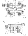
figures 2 illustrent les différentes fonctionnalités d'un dispositif selon un mode de réalisation de l'invention : lafigure 2A représente la partie distribution et protection électrique, lafigure 2B représente la partie contrôle/commande et lafigure 2C représente un mode d'adressage et de commande lumineuse. - La
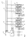
figure 3 représente un dispositif selon un mode de réalisation préféré de l'invention et illustre l'interface homme / machine. - La
figure 4 montre partiellement le fonctionnement d'un dispositif selon un mode de réalisation de l'invention.
- The
figure 1 shows the partitioning of a building in operating areas in which can be implemented a device according to the invention. - The
figures 2 illustrate the different functionalities of a device according to one embodiment of the invention: theFigure 2A represents the distribution and electrical protection part, theFigure 2B represents the control / command part and theFigure 2C represents a mode of addressing and light control. - The
figure 3 represents a device according to a preferred embodiment of the invention and illustrates the man / machine interface. - The
figure 4 partially shows the operation of a device according to one embodiment of the invention.
Dans une utilisation préférée illustrée en vue de dessus en
Le dispositif de commande 100 selon l'invention est de préférence placé de façon à optimiser les distances de câblage vers chacun des espaces 5i, notamment dans le faux plafond de la zone d'exploitation 1. Tel que schématisé dans les
Avantageusement, tel que schématisé en
De préférence, le dispositif de commande 100 selon l'invention est muni de moyens 140 permettant de déterminer la consommation électrique globale de la zone d'exploitation 1, et comprend un circuit de mesure du courant 142 au niveau de l'entrée d'alimentation 102. Avantageusement, pour optimiser l'efficacité énergétique au sein de ladite zone 1, des moyens de mesure différenciés sont prévus pour permettre des analyses de la consommation, de façon à éventuellement modifier les usages. En particulier, le dispositif 100 selon l'invention comprend, sur leur ligne respective 10210, 10220, des moyens de mesure 144, 146 de la consommation concernant deux types de sortie 110, 120, tels que l'éclairage et la climatisation. Le dispositif 100 peut alors comprendre des moyens de traitement 148 des données relatives à la consommation énergétique, par exemple une carte de circuit imprimé ; alternativement, ces données peuvent être transmises directement au réseau central de supervision 40.Preferably, the
Outre l'alimentation électrique, le dispositif 100 selon l'invention est adapté pour la commande de chacun des effecteurs 10, 20, 30, ceux-ci étant regroupés par espace d'intervention 5. Selon l'invention, le processus de mise en oeuvre est facilité, avec notamment une programmation par défaut intégrée au système et un raccordement intuitif des câbles. En particulier, tel qu'illustré en
Avantageusement, pour plus de flexibilité et augmenter l'efficacité énergétique de la zone d'exploitation 1, chaque module 150 du dispositif 100 comprend par ailleurs au moins une entrée 240 pour des paramètres externes locaux, qui sont fournis par l'intermédiaire de capteurs appropriés. Par exemple un capteur de luminosité et un capteur de présence 80 dans l'espace d'intervention 5 fournissent leurs informations à une entrée 240A muti-paramètres ; un capteur 90 informe une deuxième entrée 240B de la fermeture ou non de la fenêtre dudit espace 5,... Il est préférable, tant pour optimiser la durée de traitement des informations que pour simplifier le câblage et garantir une isolation de sécurité entre les signaux d'entrée de très basse tension et les signaux de puissance, que les différents capteurs 80, 90 fournissent un signal à des moyens de traitement 250, par exemple un microprocesseur ; avantageusement, les récepteurs de commande 50, 60 sont eux aussi directement connectés aux moyens de traitement 250.Advantageously, for greater flexibility and to increase the energy efficiency of the
Les signaux des entrées 210, 230, 240, une fois traités, sont alors transférés aux moyens de commande 260, 270, 280 de chaque sortie 110, 120, 130 du module 150 correspondant ; le transfert est réalisé via des moyens de commande centralisée du dispositif 100 selon l'invention, par exemple un microprocesseur 300, permettant une gestion optimale de la zone d'exploitation 1. Les moyens centraux 300 peuvent être autonomes et/ou reliés au réseau 40 de supervision du bâtiment par des moyens de communication 310 adaptés, par exemple selon un protocole sélectionné par un bus de terrain 310A, et/ou via ethernet 310B par le protocole TCP/IP. Les moyens centraux 300 coordonnent et gèrent l'ensemble des fonctionnalités du dispositif 100 selon l'invention, et donc veillent à l'efficacité énergétique dans la zone concernée 1 ; avantageusement, la carte de traitement 148 des données relatives à la consommation énergétique est comprise dans les moyens de commande centralisée 300.The signals of the
Selon l'invention, les moyens de commande centralisée 300 sont programmés par défaut de façon appropriée. Par exemple, il peut être prévu : une extinction des lumières 10 si le capteur de présence 80 fournit un signal négatif pendant plus de 15 minutes ; une commande graduelle fournissant un niveau constant minimal de 350 lux en journée ; une occultation automatique des fenêtres si la lumière excède 1000 lux; une interdiction de climatisation si le capteur adapté 90 détecte qu'une fenêtre est ouverte ;...According to the invention, the centralized control means 300 are programmed by default appropriately. For example, it can be provided: an extinction of the
L'installation du dispositif de contrôle 100 selon l'invention est donc facilitée : le raccordement des câbles se fait de façon intuitive au niveau de chacun des modules 150 clairement identifiés (
Selon le mode de réalisation préféré présenté, la commande 230 de la sortie d'occultation 130 est couplée à une fonction d'inversion de phase, de sorte que la sortie est un connecteur quatre points, qui se distingue clairement du raccordement trois points de la commande de climatisation 120, réalisée par une sortie de puissance d'alimentation simple, la commande étant réalisée par un contrôleur externe, propre à chaque système de climatisation, lui-même connecté au réseau central de commande et de supervision 40. Alternativement, la commande de climatisation peut aussi être réalisée par le dispositif de contrôle 100 selon l'invention, avec une modulation de type PWM pour effectivement commander des vannes et une commande multiple de vitesse pour un ventilo-convecteur. Bien que d'autres options soient possibles, avantageusement, la commande lumineuse 110 est réalisée par l'intermédiaire du protocole DALI (« Digital Addressable Lighting Interface ») afin de gérer au mieux l'éclairage, les connecteurs adaptés à ce protocole (5 points) permettant alors une identification directe.According to the preferred embodiment presented, the
Pour simplifier encore l'installation du dispositif 100, l'adressage des appareils 10 relatifs à la commande lumineuse se fait de préférence automatiquement grâce à la présence des dispositifs de protection statique 106 sur chaque départ 110. Ainsi, le dispositif 100 selon l'invention comprend un contrôleur DALI 330 sur un bus 335 commun aux quatre modules de commande 150 et donc à toutes les sorties de type éclairage 110, en parallèle de l'alimentation 10210. A la mise sous tension du dispositif 100 selon l'invention, chaque sortie 110i est individuellement et alternativement alimentée par l'intermédiaire des moyens centralisés 300 et des moyens de commande individuels 260i qui permettent de placer le dispositif de commutation 106 en mode passant ; tel que schématisé en
De préférence, les moyens centralisés 300 sont adaptés pour pouvoir être reprogrammés, notamment par la présence d'une interface de programmation, par exemple via les moyens de communication 310B, pouvant permettre une modification du paramétrage initial en cas de modification de l'utilisation du dispositif 100 selon l'invention sans nécessiter sa refonte. Par exemple, un algorithme d'efficacité énergétique peut être implémenté pour arbitrer entre les différentes charges lorsqu'une consommation excessive est déterminée. Alternativement, la configuration peut être modifiée directement sur le réseau de supervision 40 du bâtiment, via l'interface du bus de terrain 310A et ses outils de programmation appropriés.Preferably, the
Le dispositif 100 selon l'invention est également muni de moyens permettant de regrouper les espaces d'intervention 5, par exemple en cas de réorganisation de la zone d'exploitation 1. En particulier, il est possible pour l'installateur de signaler au dispositif 100 selon l'invention que deux ou trois des modules 150, voire les quatre, concernent en réalité un environnement unique, par exemple un agencement de type « open space » l' (
Tel qu'illustré en
Le dispositif 100 selon le mode préféré de l'invention illustré en
- distribution d'énergie ;
- protection contre les courts-circuits, les surcharges et les fuites à la terre de 10 mA
- la protection est en outre entièrement sélective grâce à la technologie de commutation électronique 106, ce qui permet une limitation rapide du courant de court-circuit et prévient les effets cascade de la
protection amont 104 ;
- la protection est en outre entièrement sélective grâce à la technologie de commutation électronique 106, ce qui permet une limitation rapide du courant de court-circuit et prévient les effets cascade de la
- mesure de la consommation totale du dispositif et de ses charges associées avec une précision de classe 1, associée de préférence à une mesure de la consommation générale d'éclairage et de climatisation avec une précision de 2,5 % ;
- commande de type «tout ou rien» ou graduelle des charges d'éclairage, d'occultation et de climatisation qui lui sont associées.
- energy distribution;
- short circuit, overload and earth leakage protection of 10 mA
- the protection is furthermore entirely selective thanks to the
electronic switching technology 106, which allows a rapid limitation of the short-circuit current and prevents the cascade effects of theupstream protection 104;
- the protection is furthermore entirely selective thanks to the
- measuring the total consumption of the device and its associated loads with a precision of
class 1, preferably associated with a measurement of the general consumption of lighting and air conditioning with an accuracy of 2.5%; - "all or nothing" or gradual type control of the lighting, concealment and air conditioning loads associated therewith.
Les différentes fonctions sont réalisées par un dispositif 100 de conception simple, en limitant la longueur de câble grâce à une alimentation amont partagée 102 et un point de connexion de commande 210, 230, 240 proche du lieu d'installation des capteurs 80, 90 et récepteurs 40, 50, et en réduisant le temps nécessaire à sa mise en place. Adaptée à tout type de bâtiment et à tous les protocoles ouverts, la solution selon l'invention couple de fait les fonctions de la distribution électrique et de l'automatisation, en particulier en étant apte à fournir à un système de contrôle du bâtiment 40 toutes les données relatives à la mesure, à la protection et au statut des sorties en un format natif. La capacité à commander, individuellement ou sur une maille d'espaces 5i regroupés, les charges et d'obtenir les informations relatives permet d'optimiser la consommation énergétique des bâtiments par un contrôle/commande fin. Ces avantages jouant sur l'efficacité énergétique ne sont cependant pas associés à un système figé, et le dispositif selon l'invention peut s'adapter aux évolutions du bâtiment.The various functions are performed by a
De façon générale, le dispositif 100 selon l'invention offre un compromis optimal entre facilité d'installation et variété de paramétrages, ceci avec des coûts de matériel et de mise en oeuvre réduits. En particulier, la spécialisation des entrées/sorties par type d'application, avec l'embarquement des spécificités propres concernant leur contrôle/commande, permet de faciliter le raccordement du dispositif selon l'invention ; la pré-configuration et l'adressage automatique permettent une mise en place facilitée.In general, the
Bien que le dispositif précédent 100 présente une gamme de fonctions optimisée, il est possible grâce à la conception de ses sorties 210, 230, 240, d'utiliser le dispositif précédent 100, muni de quatre modules 150 à quatre entrées et trois sorties, dans une autre configuration. En particulier, sans modifier les moyens internes de traitement des données, il est possible de paramétrer le système et de prévoir des sorties de nature différentes : par exemple, pour un bâtiment sans moyens d'occultation 30, il est possible de prévoir deux types de sorties pour l'éclairage de chaque zone, par exemple de différencier l'éclairage côté couloir 10A de l'éclairage côté fenêtre 10B, les entrées étant adaptées en conséquence. De même, si seuls deux effecteurs d'air conditionné 20 sont présents dans la zone d'exploitation 1, il est possible d'utiliser deux des sorties 120 pour des éclairages individualisés ; inversement, tel que présenté plus haut, il est possible d'utiliser une des entrées 240 pour une commande de la climatisation 120. Ainsi, il est possible d'optimiser les coûts de stockage et de fabrication, en utilisant des éléments standardisés pour une gamme complète de dispositifs de commande 100 selon l'invention adaptés à la configuration des espaces de travail 1, 5.Although the
Par ailleurs, d'autres éléments peuvent également être concernés par l'invention qui ne se limite pas aux modes de réalisation présentés. En particulier, le nombre de modules peut être ajusté à la pratique du bâtiment, avec par exemple des zones d'exploitation 1 comprenant deux, six espaces, ou plus ; le nombre d'entrées/sorties par module 150 peut être diminué ou augmenté en fonction du nombre d'entités individuelles à gérer sur la plateforme 1 de bureaux, avec par exemple une application supplémentaire vers des moyens informatiques, ou un nombre de capteurs accru. Le type de capteur peut quant à lui être adapté, tout comme la nature des sorties... ; d'autres fonctionnalités, telle que la détection de la présence de charge peuvent être ajoutées.Moreover, other elements may also be concerned by the invention which is not limited to the embodiments presented. In particular, the number of modules can be adjusted to the practice of the building, with for
Claims (10)
- Distribution and monitoring device (100) of an electrical installation (1), said installation (1) comprising a first number of entities (5), each entity (5) being provided with a second number of power effectors (10, 20, 30) of different types, said device (100) comprising:- a power supply input (102) and a second number of power electrical distribution lines (10210, 10220, 10230);- a first number of modules (150), each module (150) comprising:- a second number of outputs (110, 120, 130) of different types that can be connected to said effectors (10, 20, 30), each type of output being powered by a different distribution line (102j),- local control means (260, 270, 280) associated with each output (110, 120, 130), to control said effectors (10, 20, 30) individually, and- a third number of inputs (210, 230, 240), comprising a plurality of first inputs that can be connected to a direct control receiver (50, 60) for a plurality of outputs (110, 130), and at least one second input that can be connected to monitoring means (80, 90);- centralised control means (300) adapted for the output signals (110, 120, 130) of each module (150) to depend directly on the signals from the first inputs (210, 230) of said module (150), and for the output signals (110, 120, 130) of each module (150) to depend, in the absence of said signals from the first inputs (210, 230), on a programme of said control means (300) and on the signals from the second inputs of said module (150);- configuration means (340) on the centralised control means (300) comprising a configuration interface (346i) associated with each module (150i), such that the actuation of a plurality of interfaces (346) results in a single control for the outputs of the corresponding plurality of modules (150).
- Device (100) according to Claim 1, further comprising solid-state protection means (106) for each output (110, 120, 130) of said device (100).
- Device (100) according to one of the preceding claims, further comprising a protection device (104) at the power supply input (102).
- Device (100) according to one of the preceding claims, further comprising a bus (335) of DALI-type linked in parallel to a first output (110) of each module (150i).
- Device (100) according to one of the preceding claims, in which each module (150) further comprises means (250) for processing signals from at least the second inputs (240).
- Device (100) according to one of the preceding claims, further comprising means (140) for measuring the electrical consumption of a plurality of outputs.
- Device (100) according to one of the preceding claims, further comprising communication means (310, 320) making it possible to modify the programme of the centralised control means (300).
- Device (100) according to one of the preceding claims, comprising a casing in which a first number of distinct parts can be identified, each part comprising all the elements relating to a module (150), in particular the output connectors and configuration actuators (346).
- Device (100) according to one of the preceding claims, comprising four modules (150) each with at least three different types of outputs and four inputs.
- Device (100) according to one of the preceding claims, in which a first type of output (110) can be connected to the lighting, a second type of output (120) can be connected to the air-conditioning (20), a third type of output can be connected to covering means (30), and in which the first inputs (210, 230) relate to the first and second type of outputs (110, 130) and the second inputs are connected to sensors (80, 90).
Applications Claiming Priority (1)
| Application Number | Priority Date | Filing Date | Title |
|---|---|---|---|
| FR1000148A FR2955431B1 (en) | 2010-01-15 | 2010-01-15 | CONTROL AND PROTECTION DEVICE FOR AN ELECTRICAL INSTALLATION |
Publications (3)
| Publication Number | Publication Date |
|---|---|
| EP2346140A2 EP2346140A2 (en) | 2011-07-20 |
| EP2346140A3 EP2346140A3 (en) | 2014-04-02 |
| EP2346140B1 true EP2346140B1 (en) | 2015-09-09 |
Family
ID=42646270
Family Applications (1)
| Application Number | Title | Priority Date | Filing Date |
|---|---|---|---|
| EP10354089.4A Active EP2346140B1 (en) | 2010-01-15 | 2010-12-13 | Control and protection device for an electric facility |
Country Status (3)
| Country | Link |
|---|---|
| EP (1) | EP2346140B1 (en) |
| CN (1) | CN102156458B (en) |
| FR (1) | FR2955431B1 (en) |
Families Citing this family (3)
| Publication number | Priority date | Publication date | Assignee | Title |
|---|---|---|---|---|
| FR2992011B1 (en) | 2012-06-15 | 2015-01-23 | Jean Louis Baal | ASSEMBLY OF TECHNICAL AND ARCHITECTURAL LOTS |
| FR2993991B1 (en) * | 2012-07-30 | 2014-08-08 | Hager Electro Sas | SYSTEM FOR MEASURING THE ELECTRICAL CONSUMPTION OF MODULAR DEVICES IN A BOX |
| ES2470466B1 (en) * | 2012-12-19 | 2015-04-13 | Charles ZAMORA MOLINA | Home automation control device |
Family Cites Families (9)
| Publication number | Priority date | Publication date | Assignee | Title |
|---|---|---|---|---|
| US5170310A (en) * | 1990-11-29 | 1992-12-08 | Square D Company | Fail-resistant solid state interruption system |
| FR2688951B1 (en) * | 1992-03-19 | 1997-04-04 | Merlin Gerin | DEVICE AND INSTALLATION FOR TERMINAL ELECTRICAL DISTRIBUTION. |
| FR2693323B1 (en) * | 1992-07-01 | 1994-09-02 | Merlin Gerin | Electrical energy distribution installation with home automation communication structure. |
| FR2770014B1 (en) * | 1997-10-20 | 2000-03-10 | Schneider Electric Sa | CONTROL METHOD FOR AN ELECTRICAL INSTALLATION COMPRISING COMMUNICABLE MODULES, DEVICE AND INSTALLATION IMPLEMENTING SUCH A METHOD |
| DE10032646A1 (en) * | 2000-07-05 | 2002-01-17 | Abb Patent Gmbh | Building installation system and installation device |
| US6892145B2 (en) * | 2002-02-25 | 2005-05-10 | General Electric Company | Method and system for conditionally triggered system data capture |
| WO2005057660A1 (en) | 2003-12-05 | 2005-06-23 | Stmicroelectronics Sa | Small-surfaced active semiconductor component |
| ITPR20070079A1 (en) * | 2007-10-22 | 2009-04-23 | Mahtechs S P A | ELECTROMECHANICAL REDUNDANT UNIT FOR THE MANAGEMENT OF VARIOUS TYPE AND AMPERAGE ELECTRIC LOADS |
| FR2930091B1 (en) | 2008-04-09 | 2011-10-28 | Schneider Electric Ind Sas | STATIC RELAY SYSTEM COMPRISING TWO JFET-TYPE TRANSISTORS IN SERIES |
-
2010
- 2010-01-15 FR FR1000148A patent/FR2955431B1/en not_active Expired - Fee Related
- 2010-12-13 EP EP10354089.4A patent/EP2346140B1/en active Active
-
2011
- 2011-01-17 CN CN201110008703.5A patent/CN102156458B/en active Active
Also Published As
| Publication number | Publication date |
|---|---|
| CN102156458B (en) | 2014-09-10 |
| FR2955431A1 (en) | 2011-07-22 |
| CN102156458A (en) | 2011-08-17 |
| EP2346140A3 (en) | 2014-04-02 |
| FR2955431B1 (en) | 2011-12-23 |
| EP2346140A2 (en) | 2011-07-20 |
Similar Documents
| Publication | Publication Date | Title |
|---|---|---|
| EP0923185B1 (en) | Electrical interruption device with a communication module | |
| EP3132593B1 (en) | Controlling intelligent powered devices | |
| FR2805621A1 (en) | SYSTEM, METHOD, BUS, DEVICE, MODULE, ARRANGEMENT AND POWER SUPPLY FOR PROGRAMMABLE LIGHTING INSTALLATION | |
| EP2346140B1 (en) | Control and protection device for an electric facility | |
| CN106687872B (en) | Method for configuring a building automation system | |
| EP3258326B1 (en) | Automated control system for homes | |
| EP1376279A1 (en) | Safety communication system | |
| EP3216096B1 (en) | Electrical installation comprising an electrical panel and several electrical connection points | |
| EP0495322B1 (en) | Electrical control and monitoring system for a functional unit, in particular a house, building, ship or similar | |
| US20160299515A1 (en) | Unitary telematic system for space management, with a universal general purpose | |
| US10020955B2 (en) | Multi-networked lighting device | |
| EP3588461B1 (en) | System for controlling connected objects, corresponding control method and computer program | |
| EP2648488A1 (en) | LED lighting unit and method for controlling an electrical installation including such a lighting unit | |
| FR3017008A1 (en) | CONTROL ARRANGEMENT FOR CONTROLLING THE ELECTRICAL POWER SUPPLY OF A PLURALITY OF ELECTRICAL COMPONENTS WITH CONTINUOUS CURRENT | |
| EP3364300B1 (en) | Method for controlling a home automation installation, associated equipment and installation | |
| EP2461442A1 (en) | Unit for controlling effectors and method for controlling said unit | |
| Ahmed et al. | Automatic control of home appliances based on SCADA and IoT system | |
| EP3718253A1 (en) | System for electrically managing a plurality of electrical loads | |
| EP0911777B1 (en) | Control method for electric installation comprising communicating modules, apparatus and installation for implementing such a method | |
| FR3012582A1 (en) | STEERING BODY AND ASSEMBLY OF SUCH CONTROL BODIES | |
| EP3840142A1 (en) | Automation of the production of electrical switchboards through an identified process | |
| EP3712083A1 (en) | Electrical system with portable packaging suitable for packaging and transport of at least one micromodule for controlling electrical loads and a bench for pairing | |
| EP3764751A2 (en) | Street light for centralised management and associated management method | |
| FR3126479A3 (en) | ZONED CLIMATE CONTROL ASSEMBLY THROUGH AIR OR WATER DUCT WITH RADIO THERMOSTATS | |
| EP2590149A1 (en) | Home-automation system with reconfigurable actuators |
Legal Events
| Date | Code | Title | Description |
|---|---|---|---|
| PUAI | Public reference made under article 153(3) epc to a published international application that has entered the european phase |
Free format text: ORIGINAL CODE: 0009012 |
|
| AK | Designated contracting states |
Kind code of ref document: A2 Designated state(s): AL AT BE BG CH CY CZ DE DK EE ES FI FR GB GR HR HU IE IS IT LI LT LU LV MC MK MT NL NO PL PT RO RS SE SI SK SM TR |
|
| AX | Request for extension of the european patent |
Extension state: BA ME |
|
| REG | Reference to a national code |
Ref country code: DE Ref legal event code: R079 Ref document number: 602010027340 Country of ref document: DE Free format text: PREVIOUS MAIN CLASS: H02J0013000000 Ipc: H02J0001000000 |
|
| PUAL | Search report despatched |
Free format text: ORIGINAL CODE: 0009013 |
|
| AK | Designated contracting states |
Kind code of ref document: A3 Designated state(s): AL AT BE BG CH CY CZ DE DK EE ES FI FR GB GR HR HU IE IS IT LI LT LU LV MC MK MT NL NO PL PT RO RS SE SI SK SM TR |
|
| AX | Request for extension of the european patent |
Extension state: BA ME |
|
| RIC1 | Information provided on ipc code assigned before grant |
Ipc: H02J 3/00 20060101ALI20140224BHEP Ipc: H02J 1/00 20060101AFI20140224BHEP Ipc: H02J 4/00 20060101ALI20140224BHEP Ipc: H02J 13/00 20060101ALI20140224BHEP Ipc: H02H 7/22 20060101ALI20140224BHEP Ipc: H02J 3/14 20060101ALI20140224BHEP Ipc: H02H 7/26 20060101ALI20140224BHEP |
|
| 17P | Request for examination filed |
Effective date: 20141124 |
|
| RBV | Designated contracting states (corrected) |
Designated state(s): AL AT BE BG CH CY CZ DE DK EE ES FI FR GB GR HR HU IE IS IT LI LT LU LV MC MK MT NL NO PL PT RO RS SE SI SK SM TR |
|
| GRAP | Despatch of communication of intention to grant a patent |
Free format text: ORIGINAL CODE: EPIDOSNIGR1 |
|
| INTG | Intention to grant announced |
Effective date: 20150519 |
|
| GRAS | Grant fee paid |
Free format text: ORIGINAL CODE: EPIDOSNIGR3 |
|
| GRAA | (expected) grant |
Free format text: ORIGINAL CODE: 0009210 |
|
| AK | Designated contracting states |
Kind code of ref document: B1 Designated state(s): AL AT BE BG CH CY CZ DE DK EE ES FI FR GB GR HR HU IE IS IT LI LT LU LV MC MK MT NL NO PL PT RO RS SE SI SK SM TR |
|
| REG | Reference to a national code |
Ref country code: GB Ref legal event code: FG4D Free format text: NOT ENGLISH |
|
| REG | Reference to a national code |
Ref country code: AT Ref legal event code: REF Ref document number: 748837 Country of ref document: AT Kind code of ref document: T Effective date: 20150915 Ref country code: CH Ref legal event code: EP |
|
| REG | Reference to a national code |
Ref country code: IE Ref legal event code: FG4D Free format text: LANGUAGE OF EP DOCUMENT: FRENCH |
|
| REG | Reference to a national code |
Ref country code: DE Ref legal event code: R096 Ref document number: 602010027340 Country of ref document: DE |
|
| REG | Reference to a national code |
Ref country code: FR Ref legal event code: PLFP Year of fee payment: 6 |
|
| REG | Reference to a national code |
Ref country code: NL Ref legal event code: MP Effective date: 20150909 |
|
| PG25 | Lapsed in a contracting state [announced via postgrant information from national office to epo] |
Ref country code: GR Free format text: LAPSE BECAUSE OF FAILURE TO SUBMIT A TRANSLATION OF THE DESCRIPTION OR TO PAY THE FEE WITHIN THE PRESCRIBED TIME-LIMIT Effective date: 20151210 Ref country code: FI Free format text: LAPSE BECAUSE OF FAILURE TO SUBMIT A TRANSLATION OF THE DESCRIPTION OR TO PAY THE FEE WITHIN THE PRESCRIBED TIME-LIMIT Effective date: 20150909 Ref country code: NO Free format text: LAPSE BECAUSE OF FAILURE TO SUBMIT A TRANSLATION OF THE DESCRIPTION OR TO PAY THE FEE WITHIN THE PRESCRIBED TIME-LIMIT Effective date: 20151209 Ref country code: LV Free format text: LAPSE BECAUSE OF FAILURE TO SUBMIT A TRANSLATION OF THE DESCRIPTION OR TO PAY THE FEE WITHIN THE PRESCRIBED TIME-LIMIT Effective date: 20150909 Ref country code: LT Free format text: LAPSE BECAUSE OF FAILURE TO SUBMIT A TRANSLATION OF THE DESCRIPTION OR TO PAY THE FEE WITHIN THE PRESCRIBED TIME-LIMIT Effective date: 20150909 |
|
| REG | Reference to a national code |
Ref country code: LT Ref legal event code: MG4D |
|
| REG | Reference to a national code |
Ref country code: AT Ref legal event code: MK05 Ref document number: 748837 Country of ref document: AT Kind code of ref document: T Effective date: 20150909 |
|
| PG25 | Lapsed in a contracting state [announced via postgrant information from national office to epo] |
Ref country code: RS Free format text: LAPSE BECAUSE OF FAILURE TO SUBMIT A TRANSLATION OF THE DESCRIPTION OR TO PAY THE FEE WITHIN THE PRESCRIBED TIME-LIMIT Effective date: 20150909 Ref country code: SE Free format text: LAPSE BECAUSE OF FAILURE TO SUBMIT A TRANSLATION OF THE DESCRIPTION OR TO PAY THE FEE WITHIN THE PRESCRIBED TIME-LIMIT Effective date: 20150909 Ref country code: HR Free format text: LAPSE BECAUSE OF FAILURE TO SUBMIT A TRANSLATION OF THE DESCRIPTION OR TO PAY THE FEE WITHIN THE PRESCRIBED TIME-LIMIT Effective date: 20150909 Ref country code: ES Free format text: LAPSE BECAUSE OF FAILURE TO SUBMIT A TRANSLATION OF THE DESCRIPTION OR TO PAY THE FEE WITHIN THE PRESCRIBED TIME-LIMIT Effective date: 20150909 |
|
| PG25 | Lapsed in a contracting state [announced via postgrant information from national office to epo] |
Ref country code: NL Free format text: LAPSE BECAUSE OF FAILURE TO SUBMIT A TRANSLATION OF THE DESCRIPTION OR TO PAY THE FEE WITHIN THE PRESCRIBED TIME-LIMIT Effective date: 20150909 |
|
| PG25 | Lapsed in a contracting state [announced via postgrant information from national office to epo] |
Ref country code: IT Free format text: LAPSE BECAUSE OF FAILURE TO SUBMIT A TRANSLATION OF THE DESCRIPTION OR TO PAY THE FEE WITHIN THE PRESCRIBED TIME-LIMIT Effective date: 20150909 Ref country code: EE Free format text: LAPSE BECAUSE OF FAILURE TO SUBMIT A TRANSLATION OF THE DESCRIPTION OR TO PAY THE FEE WITHIN THE PRESCRIBED TIME-LIMIT Effective date: 20150909 Ref country code: CZ Free format text: LAPSE BECAUSE OF FAILURE TO SUBMIT A TRANSLATION OF THE DESCRIPTION OR TO PAY THE FEE WITHIN THE PRESCRIBED TIME-LIMIT Effective date: 20150909 Ref country code: SK Free format text: LAPSE BECAUSE OF FAILURE TO SUBMIT A TRANSLATION OF THE DESCRIPTION OR TO PAY THE FEE WITHIN THE PRESCRIBED TIME-LIMIT Effective date: 20150909 Ref country code: IS Free format text: LAPSE BECAUSE OF FAILURE TO SUBMIT A TRANSLATION OF THE DESCRIPTION OR TO PAY THE FEE WITHIN THE PRESCRIBED TIME-LIMIT Effective date: 20160109 |
|
| PG25 | Lapsed in a contracting state [announced via postgrant information from national office to epo] |
Ref country code: BE Free format text: LAPSE BECAUSE OF NON-PAYMENT OF DUE FEES Effective date: 20151231 Ref country code: PL Free format text: LAPSE BECAUSE OF FAILURE TO SUBMIT A TRANSLATION OF THE DESCRIPTION OR TO PAY THE FEE WITHIN THE PRESCRIBED TIME-LIMIT Effective date: 20150909 Ref country code: PT Free format text: LAPSE BECAUSE OF FAILURE TO SUBMIT A TRANSLATION OF THE DESCRIPTION OR TO PAY THE FEE WITHIN THE PRESCRIBED TIME-LIMIT Effective date: 20160111 Ref country code: RO Free format text: LAPSE BECAUSE OF FAILURE TO SUBMIT A TRANSLATION OF THE DESCRIPTION OR TO PAY THE FEE WITHIN THE PRESCRIBED TIME-LIMIT Effective date: 20150909 Ref country code: AT Free format text: LAPSE BECAUSE OF FAILURE TO SUBMIT A TRANSLATION OF THE DESCRIPTION OR TO PAY THE FEE WITHIN THE PRESCRIBED TIME-LIMIT Effective date: 20150909 |
|
| REG | Reference to a national code |
Ref country code: DE Ref legal event code: R097 Ref document number: 602010027340 Country of ref document: DE |
|
| PLBE | No opposition filed within time limit |
Free format text: ORIGINAL CODE: 0009261 |
|
| STAA | Information on the status of an ep patent application or granted ep patent |
Free format text: STATUS: NO OPPOSITION FILED WITHIN TIME LIMIT |
|
| PG25 | Lapsed in a contracting state [announced via postgrant information from national office to epo] |
Ref country code: LU Free format text: LAPSE BECAUSE OF FAILURE TO SUBMIT A TRANSLATION OF THE DESCRIPTION OR TO PAY THE FEE WITHIN THE PRESCRIBED TIME-LIMIT Effective date: 20151213 Ref country code: MC Free format text: LAPSE BECAUSE OF FAILURE TO SUBMIT A TRANSLATION OF THE DESCRIPTION OR TO PAY THE FEE WITHIN THE PRESCRIBED TIME-LIMIT Effective date: 20150909 |
|
| REG | Reference to a national code |
Ref country code: CH Ref legal event code: PL |
|
| 26N | No opposition filed |
Effective date: 20160610 |
|
| GBPC | Gb: european patent ceased through non-payment of renewal fee |
Effective date: 20151213 |
|
| PG25 | Lapsed in a contracting state [announced via postgrant information from national office to epo] |
Ref country code: DK Free format text: LAPSE BECAUSE OF FAILURE TO SUBMIT A TRANSLATION OF THE DESCRIPTION OR TO PAY THE FEE WITHIN THE PRESCRIBED TIME-LIMIT Effective date: 20150909 Ref country code: SI Free format text: LAPSE BECAUSE OF FAILURE TO SUBMIT A TRANSLATION OF THE DESCRIPTION OR TO PAY THE FEE WITHIN THE PRESCRIBED TIME-LIMIT Effective date: 20150909 |
|
| REG | Reference to a national code |
Ref country code: IE Ref legal event code: MM4A |
|
| PG25 | Lapsed in a contracting state [announced via postgrant information from national office to epo] |
Ref country code: GB Free format text: LAPSE BECAUSE OF NON-PAYMENT OF DUE FEES Effective date: 20151213 Ref country code: CH Free format text: LAPSE BECAUSE OF NON-PAYMENT OF DUE FEES Effective date: 20151231 Ref country code: IE Free format text: LAPSE BECAUSE OF NON-PAYMENT OF DUE FEES Effective date: 20151213 Ref country code: LI Free format text: LAPSE BECAUSE OF NON-PAYMENT OF DUE FEES Effective date: 20151231 |
|
| REG | Reference to a national code |
Ref country code: FR Ref legal event code: PLFP Year of fee payment: 7 |
|
| PG25 | Lapsed in a contracting state [announced via postgrant information from national office to epo] |
Ref country code: SM Free format text: LAPSE BECAUSE OF FAILURE TO SUBMIT A TRANSLATION OF THE DESCRIPTION OR TO PAY THE FEE WITHIN THE PRESCRIBED TIME-LIMIT Effective date: 20150909 Ref country code: BG Free format text: LAPSE BECAUSE OF FAILURE TO SUBMIT A TRANSLATION OF THE DESCRIPTION OR TO PAY THE FEE WITHIN THE PRESCRIBED TIME-LIMIT Effective date: 20150909 Ref country code: HU Free format text: LAPSE BECAUSE OF FAILURE TO SUBMIT A TRANSLATION OF THE DESCRIPTION OR TO PAY THE FEE WITHIN THE PRESCRIBED TIME-LIMIT; INVALID AB INITIO Effective date: 20101213 |
|
| PG25 | Lapsed in a contracting state [announced via postgrant information from national office to epo] |
Ref country code: CY Free format text: LAPSE BECAUSE OF FAILURE TO SUBMIT A TRANSLATION OF THE DESCRIPTION OR TO PAY THE FEE WITHIN THE PRESCRIBED TIME-LIMIT Effective date: 20150909 |
|
| PG25 | Lapsed in a contracting state [announced via postgrant information from national office to epo] |
Ref country code: TR Free format text: LAPSE BECAUSE OF FAILURE TO SUBMIT A TRANSLATION OF THE DESCRIPTION OR TO PAY THE FEE WITHIN THE PRESCRIBED TIME-LIMIT Effective date: 20150909 Ref country code: MT Free format text: LAPSE BECAUSE OF FAILURE TO SUBMIT A TRANSLATION OF THE DESCRIPTION OR TO PAY THE FEE WITHIN THE PRESCRIBED TIME-LIMIT Effective date: 20150909 |
|
| REG | Reference to a national code |
Ref country code: FR Ref legal event code: PLFP Year of fee payment: 8 |
|
| PG25 | Lapsed in a contracting state [announced via postgrant information from national office to epo] |
Ref country code: MK Free format text: LAPSE BECAUSE OF FAILURE TO SUBMIT A TRANSLATION OF THE DESCRIPTION OR TO PAY THE FEE WITHIN THE PRESCRIBED TIME-LIMIT Effective date: 20150909 |
|
| PG25 | Lapsed in a contracting state [announced via postgrant information from national office to epo] |
Ref country code: AL Free format text: LAPSE BECAUSE OF FAILURE TO SUBMIT A TRANSLATION OF THE DESCRIPTION OR TO PAY THE FEE WITHIN THE PRESCRIBED TIME-LIMIT Effective date: 20150909 |
|
| PGFP | Annual fee paid to national office [announced via postgrant information from national office to epo] |
Ref country code: DE Payment date: 20221227 Year of fee payment: 13 |
|
| PGFP | Annual fee paid to national office [announced via postgrant information from national office to epo] |
Ref country code: FR Payment date: 20231226 Year of fee payment: 14 |