EP3840142A1 - Automation of the production of electrical switchboards through an identified process - Google Patents
Automation of the production of electrical switchboards through an identified process Download PDFInfo
- Publication number
- EP3840142A1 EP3840142A1 EP20154385.7A EP20154385A EP3840142A1 EP 3840142 A1 EP3840142 A1 EP 3840142A1 EP 20154385 A EP20154385 A EP 20154385A EP 3840142 A1 EP3840142 A1 EP 3840142A1
- Authority
- EP
- European Patent Office
- Prior art keywords
- electrical
- equipment
- cell
- electrical panel
- management
- Prior art date
- Legal status (The legal status is an assumption and is not a legal conclusion. Google has not performed a legal analysis and makes no representation as to the accuracy of the status listed.)
- Pending
Links
Images


Classifications
-
- H—ELECTRICITY
- H02—GENERATION; CONVERSION OR DISTRIBUTION OF ELECTRIC POWER
- H02B—BOARDS, SUBSTATIONS OR SWITCHING ARRANGEMENTS FOR THE SUPPLY OR DISTRIBUTION OF ELECTRIC POWER
- H02B1/00—Frameworks, boards, panels, desks, casings; Details of substations or switching arrangements
- H02B1/015—Boards, panels, desks; Parts thereof or accessories therefor
- H02B1/04—Mounting thereon of switches or of other devices in general, the switch or device having, or being without, casing
-
- H—ELECTRICITY
- H02—GENERATION; CONVERSION OR DISTRIBUTION OF ELECTRIC POWER
- H02B—BOARDS, SUBSTATIONS OR SWITCHING ARRANGEMENTS FOR THE SUPPLY OR DISTRIBUTION OF ELECTRIC POWER
- H02B1/00—Frameworks, boards, panels, desks, casings; Details of substations or switching arrangements
- H02B1/26—Casings; Parts thereof or accessories therefor
- H02B1/30—Cabinet-type casings; Parts thereof or accessories therefor
- H02B1/32—Mounting of devices therein
-
- H—ELECTRICITY
- H02—GENERATION; CONVERSION OR DISTRIBUTION OF ELECTRIC POWER
- H02B—BOARDS, SUBSTATIONS OR SWITCHING ARRANGEMENTS FOR THE SUPPLY OR DISTRIBUTION OF ELECTRIC POWER
- H02B1/00—Frameworks, boards, panels, desks, casings; Details of substations or switching arrangements
- H02B1/20—Bus-bar or other wiring layouts, e.g. in cubicles, in switchyards
- H02B1/202—Cable lay-outs
-
- H—ELECTRICITY
- H02—GENERATION; CONVERSION OR DISTRIBUTION OF ELECTRIC POWER
- H02B—BOARDS, SUBSTATIONS OR SWITCHING ARRANGEMENTS FOR THE SUPPLY OR DISTRIBUTION OF ELECTRIC POWER
- H02B1/00—Frameworks, boards, panels, desks, casings; Details of substations or switching arrangements
- H02B1/24—Circuit arrangements for boards or switchyards
-
- H—ELECTRICITY
- H02—GENERATION; CONVERSION OR DISTRIBUTION OF ELECTRIC POWER
- H02B—BOARDS, SUBSTATIONS OR SWITCHING ARRANGEMENTS FOR THE SUPPLY OR DISTRIBUTION OF ELECTRIC POWER
- H02B1/00—Frameworks, boards, panels, desks, casings; Details of substations or switching arrangements
- H02B1/26—Casings; Parts thereof or accessories therefor
- H02B1/40—Wall-mounted casings; Parts thereof or accessories therefor
- H02B1/42—Mounting of devices therein
Definitions
- the present invention relates to the field of electrical installations and in particular to the automation of the manufacture of electrical panels adapted to their environment.
- a traditional electrical panel groups together a plurality of electrical components, in line, without any particular logic controlling the operation of all the different equipment items of an electrical installation, regardless of their distance from the panel.
- management part it is necessary to understand, in an electrical diagram, the part which is used to give the order, possibly according to a feedback of certain sensors or probes. It allows for example to activate or deactivate the power part.
- This part include in particular control, regulation, measurement systems which allow actuators to be controlled, etc.
- a traditional electrical panel is designed to include 25% free space to possibly add other components later. This greatly limits its flexibility in the event that the electrical installation has to be extended.
- the Applicant has deemed it necessary to provide an electrical panel and a method for manufacturing and installing it which makes it possible to reduce the length of cables necessary, to simplify the electrical installation, to facilitate the intervention of the various trades, to gain space and therefore to reduce installation costs and energy consumption.
- the power cell is remote or separate from the management cell, i.e. there is a gap between the two.
- a cell By cell, it is necessary to understand a module, or sector or part of the electrical panel clearly separated from the other modules, sector or parts and comprising one or more components associated with a particular function.
- a cell is a box, preferably reclosable by a cover, containing a rail on which one or more electrical components can be fixed. Unlike conventional electrical panels where all the components of a multitude of equipment are arranged in no particular order, the electrical panel of the invention seeks to establish a wiring logic, which is much more intuitive.
- the switchboard comprises two connection cells.
- the power cell contains, for example, the components operating in high current mode (circuit breakers, safety system, etc.), the management cell includes, for example, components operating in low current mode such as control electronics) and the connection cells include, for example, connection ports between an item of equipment and the components of the corresponding switchboard.
- Control electronics here designates in particular micro-controlled management units (UGM) which may be called “communicating” (UGMC). This name can designate Industrial Programmable Logic Controllers or PLCs, local management units or ASs.
- Control electronics can also refer to input-output interfaces, measurement systems, but is not limited to the sector of activity and can be applied to buildings, industries, infrastructures, etc. .
- electrical component for transporting an information signal should be understood a component whose purpose is to participate in the transmission of an information or control signal, the content of which influences the control of the power, that is, ie a management function.
- This component is not directly linked to the transmission of electrical energy to the equipment, but is for example a micro controlled management unit, a control relay ...
- the information signal comes for example from sensors, such as temperature, humidity, pressure, or external computer controls, etc.
- connection or connection ports are placed on a side face of the connection cell, in order to be easily accessible.
- lateral face is understood to mean a face which is neither the front face, generally dedicated to the cover of the cell, nor the rear face, generally intended to be oriented towards the wall on which the electrical panel is fixed.
- connection cells are separated by the connection cells, placed parallel to one another with the connection ports oriented towards a central space, allowing easy access to the connection ports.
- connection cells are shallower than the other cells so that the switchboard can be installed on a cable tray passing behind them.
- the electrical components inside the cells can be mounted next to each other but also in the depth of the panel one behind the other in order to reduce the space taken up by the electrical panel.
- the electrical components can be mounted on a rail for easy access during a professional intervention.
- the components can be superimposed, back to back, staggered so that the connection cables are interspersed in a single bundle, in order to optimize space.
- Each electrical component in the table can be identified, eg labeled, with text or code, and / or associated with a color code.
- a color code can also be assigned to the cables and / or connection ports corresponding to each type of signal in order to integrate the knowledge into the table. The technician therefore sees his work facilitated and the risk of error reduced.
- connection cables between the cells can be of standardized lengths in order to facilitate connection of the electrical panel of the invention.
- the technician can thus provide pre-cut cables during installation and therefore does not have to cut them on site.
- standardized length it is meant here that a plurality of cables pre-cut to a single length or a small number of identical lengths makes it possible to make all the connections in the switchboard. This standardized length is opposed to current practice where the operator must adjust the necessary cable length for each equipment connection.
- the electrical panel can be pre-equipped before installation in order to facilitate its assembly and reduce the level of expertise required for its installation.
- the cells can be in polycarbonate type plastic, in order to obtain better resistance to UV and be transparent to allow easier first level diagnosis, in metal for better mechanical resistance (in this case the separation of the cells allows to avoid possible magnetic disturbances avoiding the risk of malfunction) or any other material deemed appropriate by those skilled in the art.
- the cells are equipped with a cover allowing resistance to impact and / or rain, and protecting the interior of the cells from dust. More preferably, the cover of the cell placed at the top of the electrical panel is deeper so as to provide additional protection against rain for the bottom of the panel by forming a protrusion above the other cells.
- the invention also relates to an electrical installation in a building comprising at least two electrical panels according to the invention.
- the switchboards can be connected according to two connection principles: connection by "distributed driving force” (or FMDB) or connection by “direct driving force” (or FMDR).
- FMDB distributed driving force
- FMDR direct driving force
- a single circuit breaker located upstream protects several switchboards connected in series (one protection for a series of switchboards).
- direct driving force it should be understood that each switchboard connected according to this principle is protected by a circuit breaker (one protection per switchboard).
- the electrical panel is located near the equipment.
- proximity it is necessary to understand a distance of less than 20 meters, preferably less than 15 meters and more preferably less than 10 meters.
- the advantage of this proximity is to reduce the cable lengths necessary for the installation of the equipment and to facilitate the identification of the electrical components of the equipment.
- the invention relates to a method of electrically connecting at least two items of equipment, in a building, according to which the items of equipment are connected to several electrical panels according to the preceding method.
- the technical information necessary for connecting the electrical panel to the installation includes, for example, the type of electrical supply available, the location of the panel, the particular technical specifications desired by the customer or made necessary by the location of the building, the standards in force, etc ....
- the functions (or objects) for managing the equipment linked to each family of the list of families are identified according to a nomenclature of functions determined for each family, in order to establish a list of functions to be connected.
- each management function is implemented in an organized manner in a management cell of the electrical panel so as to form modules, each module corresponding to a function of a family.
- the electrical panel of the invention as well as the manufacturing method and the method of connecting the panels according to the invention make it possible to arrange the electrical installation in order to save between 40 and 60% of cable. This also makes it possible to simplify the electrical installation and make it much more intuitive, to facilitate the intervention of a professional by allowing him to easily identify the electrical panel corresponding to his trade or to be able to extend the installation. limitless electrical power and without necessarily having to cut the general power supply to avoid any risk of electric shock.
- the separation of the power and management cells makes it possible to isolate the components operating at high current conditions from the components operating at low current conditions, respectively placed in the power and management cells.
- the equipment can be classified by family and by function according to a defined nomenclature. Each family can, for example, be associated with a particular trade, or pursue a common technical objective, while the functions more precisely group together the items of equipment or group of items of equipment having a specific operation.
- Table 1 ⁇ /b> 1.
- Heat production 1.
- Boiler (s) 2.
- Heat Pump (PAC) 3.
- Co-generation 4.
- Solar panels 6.
- Urban production Heat collector with pump 8.
- Heating circuits 1. Heating circuits 3. Domestic hot water 1. Mono-energy 2. Bi-energy 3. Multi-energy 4. Cold production 1.
- Monobloc cooling unit Refrigeration unit with dry cooler 3. Cooling unit with open cooling tower 4.
- the electrical panel 1 of the prior art has several drawbacks, on the one hand, all the electrical components are arranged consecutively without any particular logic and without differentiation of the management and power components, making technical intervention complex and risky.
- the management components are not grouped by function and are therefore not easily identifiable for each different trade.
- the table is generally not presented in an intuitive way, that is to say that it is difficult to identify each component, input-output terminal, cable ... which makes its assembly and any possible intervention complex and requires a high level of qualification.
- the power cell 22 comprises a voltage disconnector 26 supplied from the top of the cell via an external power supply 27 (being here for example household AC 220V).
- the external power supply may be of any type known to those skilled in the art, in particular for example three-phase 3X400V, single-phase 230V, single-phase 110V ... and could enter the cell from any side.
- the power cell 22 further comprises a power contactor 28 making it possible to route or not the power to the pump 40 (under control of a UGMC 31, principle detailed below), a thermal relay 29 in order to cut off the power supply. in power of the contactor 28 in the event of heating, and a set of circuit breakers / differential switches 30 protecting the installation and people against the risks of overvoltage and electric shock.
- the management cell comprises a micro-controlled management unit (UGMC) 31 which here receives its electrical supply (“POWER” interface) at 24V AC from a transformer 32, here from 220VAC to 24VAC.
- POWER electrical supply
- the power supply to the UGMC passes first through a circuit breaker 33 protecting the UGMC from overvoltages.
- the transformer 32 is itself supplied from the power cell 22.
- the transformer 32 and the circuit breaker 33 could also be placed in the power cell 22 but are here in the management cell near the UGMC for clarity of reading.
- the UGMC 31 comprises a set of input-output interfaces (“INPUTS” and “OUTPUTS” respectively). Here, three analog inputs and one digital output are shown schematically.
- Each UGMC (and adjacent components) or module required in the table corresponds to a function (here, a single function: the heating circuit).
- a function here, a single function: the heating circuit.
- the UGMCs used are UGMCs of brands and models well known to those skilled in the art and are standardized for each function. In other words, depending on the equipment to be connected, some I / O may not be connected. This thus allows a person skilled in the art to always work with the same modules and helps to make the electrical panel more intuitive.
- the input interfaces of the UGMC 31 are respectively connected to terminals 35 'located in the connection cell 24' linked to the management part of the switchboard.
- the terminals 35 are connected to a water return temperature sensor 36 and a water outlet temperature sensor 37, for which the UGMC 31 receives feedback S in the form of an analog signal.
- the 35 'terminals can be labeled (here XAI1, XAI2 and XAI3 for terminal block X, analog input 1,2 and 3) and in colors corresponding to their function in order to make their connection more intuitive.
- the power connections for the probes are not shown for clarity but are obvious to a person skilled in the art.
- the UGMC 31 sends a digital signal, via the digital output, to a relay 34, so that the latter lets or not the 24VAC signal from transformer 32 to contactor 28 located in the power cell so that the latter in turn supplies or not the pump 40 with power (220VAC) via a terminal 35 located in the connection cell 24.
- All the components of all the cells in the switchboard are here mounted on rails 38. The installation has not been shown with all the feedback signals to the UGMC or the control and power signals of the devices of the equipment in a concern of clarity. It is for example possible that valves 42 at the inlet and outlet of the heating circuit 35 can be controlled by the UGMC. Likewise, it is also possible for information signals on the state of contactor 28 and thermal relay 29 to return to the UGMC.
- the water flow and return temperature sensors 36 and 37 indicate to the UGMC 31 the temperature of hot water 39 at the inlet and cold water 41 at the outlet of the heating circuit 35.
- the UGMC 31 determines according to its internal programming whether the pump 40 must be activated or deactivated, and if necessary, sends a signal to the power contactor 28 so that the latter switches and respectively transmits or cuts the power supply to the pump 40.
- internal programming it is necessary to understand the operating requirements of the heating circuit 35 retransmitted in the form of a computer program uploaded to the UGMC, for example from a centralized control station.
- the arrival of hot in the heating circuit 35 by the pump 40 is managed by the table according to the invention.
- connection cells 24 and 24 ′ are arranged at the top and at the bottom of the switchboard, while the power 22 and management cells 23 are arranged to the left and to the right of the switchboard.
- terminals 35 and 35 ' can be independently arranged towards the inside of the switchboard (ie in the central empty zone located between the 4 cells of the switchboard), or towards the outside thereof depending on the connection. more convenient for those skilled in the art.
- connections between the terminals 35, 35 'and the UGMC 31 are here each represented by a cable directly making the connection between the latter.
- terminals 35 and 35 ' are connected to an intermediate terminal block positioned (here not shown for the sake of clarity) on a rail located in the corresponding connection box. (respectively 24 and 24 ') in order to make the installation or the manufacture of the switchboard easier and more intuitive.
- an electrical panel 121 can be provided so that the connection cells 124 and 124 'are shallower than the power 122 and management cells 123 so that the connection cables leaving the panel can pass through a space 143 created between the connecting cells 124, 124 'and a support 142 on which the table 121 is placed (for example a wall).
- the power cell 122 of the switchboard can be provided to be even deeper than the management cell to form a protuberance 145 and protect the connection 124, 124 'and management cells 123 from bad weather.
- the electrical components 144 can also be mounted in the depth of the switchboard, for example on different rails 138 located at different depths, in addition to being able to be mounted side by side on the same rail. This makes it possible to optimize the space as well as possible and to make the installation more practical and careful.
- a first step A the customer is asked for general information concerning the electrical installation. For example, we ask for the location of the installation (outdoor environment, cellar, electrical room, etc.), the available power supply (3x400V + N, 220V single-phase, etc.), the breaking capacity of the installation ( 6KA, 25KA, 36kA %), the desired panel material (metal, polycarbonate %), the quality of the desired project (LEED certification, BREAM, building classification ...) etc.
- a second step B the installation is virtually sectioned for the first time by identifying and categorizing the equipment of the installation by families of equipment to connect.
- a fourth step D the components to be installed for each management function are selected and they are arranged in an organized manner in the management cell of the electrical panel in the form of modules.
- the “heating circuits” function is implemented in the form of the UGMC 31 and its adjacent components (the circuit breaker 33, the transformer 32 and the relay 34) corresponding to a module / function.
- the components for transporting the power (or electrical energy) to the equipment necessary for connecting the equipment are determined, then they are installed in the power cell. In the table of the figure 2 , it was therefore determined and then installed: the circuit breakers 30, the thermal relay 29, the contactor 28 and the disconnector 26.
- the appropriate electrical connections are established (as detailed previously for the figure 2 ) between the management functions, the components for transporting electrical energy to the equipment and the connection terminals of the connection cells.
- Steps A to E, before installing the components can advantageously be done using software or a dedicated application.
- the software can be arranged to offer the components according to the information entered by a user.
- the software or the application can be associated with an interface asking the user questions according to a precise sequence on the content of the electrical installation, the equipment to be connected, the distances between the equipment or related metric data. in terms of installation, ...
- the user can be offered a choice of components, for example a choice of brands or prices.
- the software or the application can be programmed to determine the diameter of the cables according to the powers to be managed, the type of driving force best suited (FMDR and / or FMDB), the colors of the cables to be used according to the location functions in the table, the dimensions of the table and its organization, ie, the distribution of the components in the cells.
- the process can thus lead, for example, to the automatic drawing of the electrical plan of the installation and / or to an estimate for producing the panel (s).
- an operator can be provided with the composition of a custom-made table to be assembled. The operator in question then does not need any particular skill in electricity and the assembly can be done industrially.
- a manufacturer can configure the electrical panel (s) of its installation and have them manufactured "in the factory" or in the workshop "by an operator.
- the invention has been explained for an electrical panel managing only a heating circuit in a building.
- the invention is not limited to the management of a single device, a single function or a single family and can on the same principle manage a much more complete installation.
- the table for sectioning the electrical installation into families and functions on pages 10 and 11 is provided by way of example and does not represent an absolute and exhaustive version of the possible sectioning of the electrical installation of a building. In particular, it is possible to group the families / functions together differently and to add other families / functions.
- the invention is not limited to an electrical installation of a building and it is conceivable to transpose the principle and the electrical panel described here to any type of electrical installation.
- each switchboard includes the safety components allowing it to trip (one protection per switchboard).
- FMDR direct motive force
- This configuration is particularly when the functions are located in a confined space, such as for example a technical room, an air handling unit, etc.
- the driving force of the functions is distributed directly to the field components.
- the safety signal and communication network are distributed within the electrical panel. This configuration allows up to 40% savings in cable length.
- the invention therefore relates not only to multi-function panels as described above, but also to single-function panels.
- a table generally comprises only three cells: a power cell, a management or control cell and a connection cell.
- This so-called single-function table is positioned as close as possible to the element to be managed. Its composition is generally simple since it manages only one function and it can advantageously be supplied already equipped with all its components, electrically connected in an adequate manner to each other and to the terminals of the connection cell. The installer can thus place a series of pre-equipped panels, as close as possible to the equipment or circuit corresponding to the function to be managed.
Abstract
La présente invention concerne le domaine des installations électriques et en particulier l'automatisation de la fabrication de tableaux électriques adaptés à leur environnement. Les composants des tableaux électriques de l'invention sont organisés dans des cellules distinctes selon qu'ils sont alimentés par un courant fort ou un courant faible. Les composants sont sélectionnés et organisés selon leur fonction et la famille d'équipement qu'ils gèrent ou alimentent, de façon identifiée. Cela permet l'intervention simplifiée et en toute sécurité d'un opérateur sur le tableau, même non-qualifié.The present invention relates to the field of electrical installations and in particular to the automation of the manufacture of electrical panels adapted to their environment. The components of the electrical panels of the invention are organized in separate cells according to whether they are supplied by a strong current or a weak current. The components are selected and organized according to their function and the equipment family they manage or supply, in an identified way. This allows the simplified and safe intervention of an operator on the switchboard, even non-qualified.
Description
La présente invention concerne le domaine des installations électriques et en particulier l'automatisation de la fabrication de tableaux électriques adaptés à leur environnement.The present invention relates to the field of electrical installations and in particular to the automation of the manufacture of electrical panels adapted to their environment.
Un tableau électrique traditionnel regroupe une pluralité de composants électriques, en ligne, sans logique particulière contrôlant le fonctionnement de tous les différents équipements d'une installation électrique, indifféremment de leur distance au tableau.A traditional electrical panel groups together a plurality of electrical components, in line, without any particular logic controlling the operation of all the different equipment items of an electrical installation, regardless of their distance from the panel.
Par équipement, il faut comprendre un appareil ou un groupe d'appareils de même type destinés à être raccordé au réseau électrique, comme par exemple un groupe de lampes (équipement éclairage), un radiateur ou un groupe de radiateur, un chauffe-eau, une machine industrielle, un four, une chambre froide, etc..., éventuellement lié à un local particulier (éclairages dans une pièce).By equipment, it is necessary to understand a device or a group of devices of the same type intended to be connected to the electrical network, such as for example a group of lamps (lighting equipment), a radiator or a group of radiator, a water heater, an industrial machine, an oven, a cold room, etc ..., possibly linked to a particular room (lighting in a room).
Par composants électriques, il faut comprendre l'ensemble des composants formant l'interface entre le réseau électrique et l'équipement tels que les disjoncteurs, les systèmes de sécurité, les unités de gestion micro contrôlées comme les automates programmables industriels, les interfaces entrées-sorties... Ces composants peuvent être regroupés en deux grands objets, ou fonctions : la gestion et la puissance, bien connues de l'homme du métier.By electrical components, it is necessary to understand all the components forming the interface between the electrical network and the equipment such as circuit breakers, security systems, micro-controlled management units such as industrial programmable controllers, input interfaces. outputs ... These components can be grouped into two major objects, or functions: management and power, well known to those skilled in the art.
Par partie gestion, il faut comprendre, dans un schéma électrique, la partie qui sert à donner l'ordre, éventuellement en fonction d'un retour de certains capteurs ou sondes. Elle permet par exemple d'activer ou d'éteindre la partie puissance. Cette partie incluent notamment la commande, la régulation, les systèmes de mesures qui permettent de piloter des actionneurs, etc...By management part, it is necessary to understand, in an electrical diagram, the part which is used to give the order, possibly according to a feedback of certain sensors or probes. It allows for example to activate or deactivate the power part. This part include in particular control, regulation, measurement systems which allow actuators to be controlled, etc.
Par partie puissance, il faut comprendre, dans un schéma électrique, la partie qui permet d'acheminer la puissance vers le récepteur électrique. Elle comprend également les fonctions de sécurité et de dérogation.By power part, it is necessary to understand, in an electrical diagram, the part which makes it possible to route the power towards the electrical receiver. It also includes the safety and override functions.
Ainsi, cette centralisation de la gestion et de la puissance nécessite alors une multitude de câbles de longueurs importantes pour connecter le tableau aux équipements ou à leurs composants sur le terrain. Cela complexifie l'installation, regroupant tous les composants électriques au même endroit, rendant l'identification d'un problème ou l'intervention sur un composant particulier difficile.Thus, this centralization of management and power then requires a multitude of cables of long lengths to connect the switchboard to the equipment or their components in the field. This complicates the installation, grouping all the electrical components together in one place, making it difficult to identify a problem or work on a particular component.
Par ailleurs, les nombreux câbles de grande longueur nécessaires pour une installation électrique traditionnelle coûtent excessivement cher et conduisent à des pertes énergétiques inutiles proportionnelles à la longueur et au nombre de câbles.Moreover, the numerous cables of great length necessary for a traditional electrical installation are excessively expensive and lead to unnecessary energy losses proportional to the length and the number of cables.
De plus, un tableau électrique traditionnel est prévu pour comprendre 25% de place libre pour éventuellement ajouter ultérieurement d'autres composants. Cela limite ainsi fortement sa flexibilité au cas où l'installation électrique doit être étendue.In addition, a traditional electrical panel is designed to include 25% free space to possibly add other components later. This greatly limits its flexibility in the event that the electrical installation has to be extended.
Enfin, les tableaux électriques traditionnels sont conçus de manière plane (ou en deux dimensions) et résultent en une perte de place supplémentaire. Par plane, il faut comprendre que chaque composant est à côté d'un autre, tous les fils sont connectés par l'arrière du tableau, et la profondeur de celui-ci n'est ainsi jamais exploitée.Finally, traditional electrical panels are designed flat (or in two dimensions) and result in an additional loss of space. By plane, it should be understood that each component is next to another, all the wires are connected by the back of the switchboard, and the depth of the latter is thus never exploited.
Dans l'optique de pallier ces problèmes, la demanderesse a jugé nécessaire de proposer un tableau électrique et une méthode pour le fabriquer et l'installer permettant de réduire conséquemment la longueur de câbles nécessaire, de simplifier l'installation électrique, de faciliter l'intervention des différents corps de métier, de gagner en place et donc de réduire les coûts d'installation et de la consommation énergétique.With a view to alleviating these problems, the Applicant has deemed it necessary to provide an electrical panel and a method for manufacturing and installing it which makes it possible to reduce the length of cables necessary, to simplify the electrical installation, to facilitate the intervention of the various trades, to gain space and therefore to reduce installation costs and energy consumption.
A cette fin, l'invention concerne un tableau électrique pour raccorder au moins un équipement à un réseau électrique comprenant :
- une cellule de puissance comprenant au moins un composant électrique de transport de l'énergie électrique vers l'équipement,
- si nécessaire, une cellule de gestion comprenant au moins un composant électrique de transport d'un signal d'information, et
- au moins une cellule de raccordement comprenant des ports de connexion de l'équipement aux composants du tableau lui correspondant.
- a power cell comprising at least one electrical component for transporting electrical energy to the equipment,
- if necessary, a management cell comprising at least one electrical component for transporting an information signal, and
- at least one connection cell comprising ports for connecting the equipment to the components of the corresponding switchboard.
De préférence, la cellule de puissance est distante ou séparée de la cellule de gestion, c'est-à-dire qu'il existe un espacement entre les deux.Preferably, the power cell is remote or separate from the management cell, i.e. there is a gap between the two.
Par cellule, il faut comprendre un module, ou secteur ou partie du tableau électrique clairement séparé(e) des autres modules, secteur ou parties et comprenant un ou plusieurs composants associés à une fonction particulière. Une cellule est un boitier, de préférence refermable par un couvercle, contenant un rail sur lequel peuvent être fixés un ou plusieurs composants électriques. Contrairement aux tableaux électriques classiques ou tous les composants d'une multitude d'équipements sont disposés sans ordre particulier, le tableau électrique de l'invention cherche à instaurer une logique de câblage, qui est beaucoup plus intuitive.By cell, it is necessary to understand a module, or sector or part of the electrical panel clearly separated from the other modules, sector or parts and comprising one or more components associated with a particular function. A cell is a box, preferably reclosable by a cover, containing a rail on which one or more electrical components can be fixed. Unlike conventional electrical panels where all the components of a multitude of equipment are arranged in no particular order, the electrical panel of the invention seeks to establish a wiring logic, which is much more intuitive.
De préférence le tableau comprend deux cellules de raccordement.Preferably the switchboard comprises two connection cells.
Par composant électrique de transport de l'énergie électrique vers l'équipement il faut comprendre un composant dont le but est de participer à l'acheminement de l'énergie nécessaire au fonctionnement de l'équipement, c'est-à-dire la fonction de puissance, comme par exemple un contacteur de puissance, un disjoncteur de puissance...By electrical component for transporting electrical energy to the equipment, it is necessary to understand a component whose purpose is to participate in the routing of the energy necessary for the operation of the equipment, that is to say the function power, such as a power contactor, a power circuit breaker, etc.
La cellule de puissance contient par exemple les composants fonctionnant en régime de courant fort (disjoncteurs, système de sécurité...), la cellule de gestion comprend par exemple les composants fonctionnant en régime de courant faible tels que l'électronique de contrôle) et les cellules de raccordements comprennent par exemple des ports de connexion entre un équipement et les composants du tableau lui correspondant.
L'électronique de contrôle désigne ici notamment des unités de gestion micro contrôlées (UGM) que l'on peut appeler « communicantes » (UGMC). Cette appellation peut désigner les Automate Programmable Industriel ou API, les unités de gestion locale ou UGL. L'électronique de contrôle peut également désigner les interfaces entrées-sorties, les systèmes de mesures, mais n'est pas limitatif du secteur d'activité et peut s'appliquer aussi bien aux bâtiments, aux industries, aux infrastructures......The power cell contains, for example, the components operating in high current mode (circuit breakers, safety system, etc.), the management cell includes, for example, components operating in low current mode such as control electronics) and the connection cells include, for example, connection ports between an item of equipment and the components of the corresponding switchboard.
Control electronics here designates in particular micro-controlled management units (UGM) which may be called “communicating” (UGMC). This name can designate Industrial Programmable Logic Controllers or PLCs, local management units or ASs. Control electronics can also refer to input-output interfaces, measurement systems, but is not limited to the sector of activity and can be applied to buildings, industries, infrastructures, etc. .
Par courant fort, il faut comprendre le courant ayant pour fonction de transporter l'énergie électrique dans le réseau. Dans le tableau électrique de l'invention, il s'agit du courant transportant l'énergie depuis l'alimentation électrique en amont du tableau vers l'équipement en aval.By strong current, we must understand the current having the function of transporting electrical energy in the network. In the electrical panel of the invention, this is the current carrying energy from the electrical supply upstream of the panel to the downstream equipment.
Par courant faible, il faut comprendre le courant ayant pour but de transmettre un signal d'information ou de commande.By low current, we must understand the current intended to transmit an information or control signal.
Par composant électrique de transport d'un signal d'information il faut comprendre un composant dont le but est de participer à la transmission d'un signal d'information ou de commande dont le contenu influence la commande de la puissance, c'est-à-dire une fonction de gestion. Ce composant n'est pas lié directement à la transmission de l'énergie électrique vers l'équipement, mais est par exemple une unité de gestion micro contrôlée, un relais de commande... Le signal d'information provient par exemple de capteurs, comme des sondes de températures, d'humidité, de pression, ou des commandes informatiques externes, etc...By electrical component for transporting an information signal should be understood a component whose purpose is to participate in the transmission of an information or control signal, the content of which influences the control of the power, that is, ie a management function. This component is not directly linked to the transmission of electrical energy to the equipment, but is for example a micro controlled management unit, a control relay ... The information signal comes for example from sensors, such as temperature, humidity, pressure, or external computer controls, etc.
De préférence, les ports de connexion ou de raccordement sont placés sur une face latérale de la cellule de raccordement, afin d'être accessibles facilement. Par face latérale on entend une face qui n'est ni la face avant, généralement dédiée au couvercle de la cellule, ni la face arrière, généralement destinée à être orientée vers le mur sur lequel est fixé le tableau électrique.Preferably, the connection or connection ports are placed on a side face of the connection cell, in order to be easily accessible. The term “lateral face” is understood to mean a face which is neither the front face, generally dedicated to the cover of the cell, nor the rear face, generally intended to be oriented towards the wall on which the electrical panel is fixed.
Avantageusement, les cellules de puissance et de gestion sont séparées par les cellules de raccordement, placées parallèlement l'une à l'autre avec les ports de connexion orientés vers un espace central, permettant un accès facile aux ports de connexion.Advantageously, the power and management cells are separated by the connection cells, placed parallel to one another with the connection ports oriented towards a central space, allowing easy access to the connection ports.
De préférence, les cellules de raccordement sont moins profondes que les autres cellules afin que le tableau puisse être installé sur un chemin de câble passant derrière celles-ci.Preferably, the connection cells are shallower than the other cells so that the switchboard can be installed on a cable tray passing behind them.
De préférence, les composants électriques à l'intérieur des cellules peuvent être montés à côté les uns des autres mais également dans la profondeur du tableau l'un derrière l'autre afin de réduire la place prise par le tableau électrique. A cette fin, les composants électriques peuvent être montés sur rail pour en faciliter l'accès lors d'une intervention d'un professionnel. Dans ce cas, les composants peuvent être superposés, dos à dos, en quinconce de façon à ce que les câbles de connexion s'intercalent en un faisceau unique, afin d'optimiser l'espace.Preferably, the electrical components inside the cells can be mounted next to each other but also in the depth of the panel one behind the other in order to reduce the space taken up by the electrical panel. To this end, the electrical components can be mounted on a rail for easy access during a professional intervention. In this case, the components can be superimposed, back to back, staggered so that the connection cables are interspersed in a single bundle, in order to optimize space.
Chaque composant électrique dans le tableau peut être identifié, par exemple étiqueté, avec un texte ou un code, et/ou associé à un code couleur. Un code couleur peut également être attribué aux câbles et/ou aux ports de raccordement correspondant à chaque type de signal afin d'intégrer la connaissance dans le tableau. Le technicien voit donc son travail facilité et le risque d'erreur diminuer.Each electrical component in the table can be identified, eg labeled, with text or code, and / or associated with a color code. A color code can also be assigned to the cables and / or connection ports corresponding to each type of signal in order to integrate the knowledge into the table. The technician therefore sees his work facilitated and the risk of error reduced.
Les câbles de connexion entre les cellules peuvent être de longueurs standardisées afin de faciliter le branchement du tableau électrique de l'invention. Le technicien peut ainsi apporter des câbles prédécoupés lors de l'installation et ne doit donc pas les découper sur place. Par longueur standardisée, on signifie ici qu'une pluralité de câbles prédécoupés à une longueur unique ou un faible de nombre de longueurs identiques permet de réaliser toutes les connections dans le tableau. Cette longueur standardisée s'oppose à la pratique actuelle ou l'opérateur doit ajuster à chaque raccordement d'équipement la longueur du câble nécessaire.The connection cables between the cells can be of standardized lengths in order to facilitate connection of the electrical panel of the invention. The technician can thus provide pre-cut cables during installation and therefore does not have to cut them on site. By standardized length, it is meant here that a plurality of cables pre-cut to a single length or a small number of identical lengths makes it possible to make all the connections in the switchboard. This standardized length is opposed to current practice where the operator must adjust the necessary cable length for each equipment connection.
Le tableau électrique peut être pré-équipé avant installation afin de faciliter le montage de celui-ci et de diminuer le niveau d'expertise nécessaire à son installation.The electrical panel can be pre-equipped before installation in order to facilitate its assembly and reduce the level of expertise required for its installation.
Les cellules peuvent être en plastique de type polycarbonate, afin d'obtenir une meilleure résistance aux U.V. et d'être transparentes pour permettre un diagnostic de premier niveau plus facile, en métal pour une meilleure résistance mécanique (dans ce cas la séparation des cellules permet d'éviter d'éventuelles perturbations magnétiques évitant les risques de dysfonctionnement) ou en tout autre matériau jugé approprié par l'homme du métier.The cells can be in polycarbonate type plastic, in order to obtain better resistance to UV and be transparent to allow easier first level diagnosis, in metal for better mechanical resistance (in this case the separation of the cells allows to avoid possible magnetic disturbances avoiding the risk of malfunction) or any other material deemed appropriate by those skilled in the art.
De préférence, les cellules sont équipées d'un capot permettant une résistance aux chocs et/ou à la pluie, et protégeant l'intérieur des cellules de la poussière. De préférence encore, le capot de la cellule placée en haut du tableau électrique est plus profonde de manière à offrir une protection supplémentaire contre la pluie pour le bas du tableau en formant une protubérance au-dessus des autres cellules.Preferably, the cells are equipped with a cover allowing resistance to impact and / or rain, and protecting the interior of the cells from dust. More preferably, the cover of the cell placed at the top of the electrical panel is deeper so as to provide additional protection against rain for the bottom of the panel by forming a protrusion above the other cells.
L'invention porte également sur une installation électrique dans un bâtiment comprenant au moins deux tableaux électriques selon l'invention. Les tableaux peuvent être raccordés suivant deux principes de raccordement : le raccordement par « force motrice distribuée » (ou FMDB) ou le raccordement par « force motrice directe » (ou FMDR). Par force motrice distribuée, il faut comprendre qu'un unique disjoncteur situé en amont protège plusieurs tableaux raccordés en série (une protection pour une série de tableaux). Par force motrice directe, il faut comprendre que chaque tableau raccordé suivant ce principe est protégé par un disjoncteur (une protection par tableau).The invention also relates to an electrical installation in a building comprising at least two electrical panels according to the invention. The switchboards can be connected according to two connection principles: connection by "distributed driving force" (or FMDB) or connection by "direct driving force" (or FMDR). By distributed motive power, it should be understood that a single circuit breaker located upstream protects several switchboards connected in series (one protection for a series of switchboards). By direct driving force, it should be understood that each switchboard connected according to this principle is protected by a circuit breaker (one protection per switchboard).
Il est de plus revendiqué l'utilisation du tableau électrique de l'invention dans une installation électrique d'un bâtiment.It is further claimed the use of the electrical panel of the invention in an electrical installation of a building.
L'invention concerne en outre un procédé de raccordement électrique d'un équipement comprenant les étapes de :
- on raccorde les fonctions de puissance de l'équipement à ses composants de transport de l'énergie électrique situés dans une première zone ou cellule de puissance d'un tableau électrique,
- on raccorde les fonctions de gestion de l'équipement à ses composants de transport d'un signal d'information ou de commande situés dans une seconde zone, ou cellule de gestion, du même tableau électrique,
- the power functions of the equipment are connected to its electrical energy transport components located in a first zone or power cell of an electrical panel,
- the management functions of the equipment are connected to its transport components for an information signal or control located in a second zone, or management cell, of the same electrical panel,
De préférence, le tableau électrique se situe à proximité de l'équipement.Preferably, the electrical panel is located near the equipment.
Par à proximité, il faut comprendre une distance inférieure à 20 mètres, de préférence inférieure à 15 mètres et de préférence encore inférieure à 10 mètres. L'intérêt de cette proximité est de réduire les longueurs de câble nécessaire à l'installation de l'équipement et de faciliter l'identification des composants électriques de l'équipement.By proximity, it is necessary to understand a distance of less than 20 meters, preferably less than 15 meters and more preferably less than 10 meters. The advantage of this proximity is to reduce the cable lengths necessary for the installation of the equipment and to facilitate the identification of the electrical components of the equipment.
De plus, l'invention porte sur un procédé de raccordement électrique d'au moins deux équipements, dans un bâtiment, selon lequel les équipements sont raccordés à plusieurs tableaux électriques selon le procédé précédent.In addition, the invention relates to a method of electrically connecting at least two items of equipment, in a building, according to which the items of equipment are connected to several electrical panels according to the preceding method.
Enfin, l'invention porte sur une méthode de fabrication d'un tableau électrique pour raccorder les équipements d'une installation, le tableau électrique comprenant au moins une cellule de puissance, une cellule de gestion et une cellule de raccordement, comprenant les étapes de :
- on détermine les informations techniques nécessaires au raccordement du tableau électrique à l'installation,
- on identifie et on catégorise les équipements à connecter au tableau électrique par famille selon une nomenclature de familles déterminée en fonction du type d'installation pour établir une liste de familles d'équipements à raccorder,
- on identifie les fonctions (ou objets) de gestion des équipements liées à chaque famille de la liste de familles, pour établir une liste de fonctions à raccorder,
- on implante chaque fonction de gestion de façon organisée dans une cellule de gestion du tableau électrique,
- on détermine les composants de de transport de l'énergie électrique vers les équipements nécessaires au raccordement des équipements et on les installe dans une cellule de puissance du tableau électrique,
- on établit les connections électriques appropriées entre les fonctions de gestion, les composants de de transport de l'énergie électrique vers les équipements et les ports de raccordement compris dans la cellule de raccordement.
- the technical information necessary for connecting the electrical panel to the installation is determined,
- the equipment to be connected to the electrical panel is identified and categorized by family according to a nomenclature of families determined according to the type of installation to establish a list of families of equipment to be connected,
- the functions (or objects) for managing the equipment linked to each family in the list of families are identified, in order to establish a list of functions to be connected,
- each management function is implemented in an organized manner in an electrical panel management unit,
- the components for transporting electrical energy to the equipment necessary for connecting the equipment are determined and installed in a power cell of the electrical panel,
- the appropriate electrical connections are established between the management functions, the components for transporting electrical energy to the equipment and the connection ports included in the connection cell.
Les informations techniques nécessaires au raccordement du tableau électrique à l'installation comprennent par exemple le type d'alimentation électrique disponible, la localisation du tableau, les spécifications techniques particulières souhaitées par le client ou rendues nécessaires par l'implantation du bâtiment, les normes en vigueur, etc....The technical information necessary for connecting the electrical panel to the installation includes, for example, the type of electrical supply available, the location of the panel, the particular technical specifications desired by the customer or made necessary by the location of the building, the standards in force, etc ....
Avantageusement, on identifie les fonctions (ou objets) de gestion des équipements liées à chaque famille de la liste de familles selon une nomenclature de fonctions déterminée pour chaque famille, pour établir une liste de fonctions à raccorder.Advantageously, the functions (or objects) for managing the equipment linked to each family of the list of families are identified according to a nomenclature of functions determined for each family, in order to establish a list of functions to be connected.
Avantageusement encore, on implante chaque fonction de gestion de façon organisée dans une cellule de gestion du tableau électrique de manière à former des modules, chaque module correspondant à une fonction d'une famille.Again advantageously, each management function is implemented in an organized manner in a management cell of the electrical panel so as to form modules, each module corresponding to a function of a family.
Le tableau électrique de l'invention ainsi que la méthode de fabrication et la méthode de raccordement des tableaux selon l'invention permettent d'agencer l'installation électrique afin d'économiser entre 40 et 60% de câble. Cela permet également de simplifier l'installation électrique et de la rendre beaucoup plus intuitive, de faciliter l'intervention d'un professionnel en lui permettant d'identifier facilement le tableau électrique correspondant à son corps de métier ou encore de pouvoir étendre l'installation électrique sans limite et sans devoir nécessairement couper l'alimentation générale pour éviter tout risque d'électrisation.
De plus, la séparation des cellules de puissance et de gestion permet d'isoler les composants fonctionnant en régime de courant fort des composants fonctionnant en régime de courant faible, respectivement placés dans les cellules de puissance et de gestion. Cela permet ainsi, pour l'homme du métier, lors d'une intervention dans le tableau, d'être assuré de différencier la partie de tableau directement électriquement dangereuse (i.e. la partie en régime de courant fort où les courants et potentiellement les tensions (par exemples, les basses tensions, entre 50 et 1000VAC et entre 120 et 1500VDC) élevés peuvent occasionner des blessures sévères ou la mort à un humain par électrisation) de la partie où le régime de courant n'est plus directement mortellement dangereux pour un humain (i.e. le régime de courant faible, où l'on retrouve également potentiellement des tensions moins élevées, comme par exemple les très basses tensions inférieures à 50VAC ou 120VDC).The electrical panel of the invention as well as the manufacturing method and the method of connecting the panels according to the invention make it possible to arrange the electrical installation in order to save between 40 and 60% of cable. This also makes it possible to simplify the electrical installation and make it much more intuitive, to facilitate the intervention of a professional by allowing him to easily identify the electrical panel corresponding to his trade or to be able to extend the installation. limitless electrical power and without necessarily having to cut the general power supply to avoid any risk of electric shock.
In addition, the separation of the power and management cells makes it possible to isolate the components operating at high current conditions from the components operating at low current conditions, respectively placed in the power and management cells. This thus makes it possible, for those skilled in the art, during an intervention in the switchboard, to be sure of differentiating the part of the switchboard that is directly electrically dangerous (ie the part in high current mode where the currents and potentially the voltages ( for example, low voltages, between 50 and 1000VAC and between 120 and 1500VDC) high can cause severe injury or death to a human by electric shock) from the part where the current is no longer directly fatal to a human (ie the low current regime, where lower voltages are also potentially found, such as for example very low voltages below 50VAC or 120VDC).
L'invention sera mieux comprise à l'aide de la description suivante d'une forme de réalisation de l'invention, en référence aux figures en annexe sur lesquelles :
- La
figure 1 est un schéma d'un tableau électrique de l'art antérieur pour commande d'un chauffe-eau, - la
figure 2 est un schéma d'un tableau électrique selon l'invention pour commande d'un circuit de chauffage, - la
figure 3 illustre la vue de droite du tableau électrique de lafigure 2 , - la
figure 4 illustre le procédé de fabrication d'un tableau électrique selon l'invention,
- The
figure 1 is a diagram of an electrical panel of the prior art for controlling a water heater, - the
figure 2 is a diagram of an electrical panel according to the invention for controlling a heating circuit, - the
figure 3 illustrates the right view of the electrical panel of thefigure 2 , - the
figure 4 illustrates the method of manufacturing an electrical panel according to the invention,
Les équipements peuvent être classifiés par famille et par fonction selon une nomenclature définie. Chaque famille peut par exemple être associée à un corps de métier particulier, ou poursuivre un objectif technique commun, tandis que les fonctions regroupent de manière plus précise les équipements ou groupe d'équipements ayant un fonctionnement spécifique. Par exemple, le tableau ci-dessous regroupe les familles et fonctions dans un bâtiment :
En référence à la
- le disjoncteur deux ampères de
protection 2 protège le programmateur 3 d'une surcharge électrique, tout en permettant son alimentation directe depuis l'alimentation électrique externe ; - le disjoncteur de puissance 4 protège le contacteur de puissance 5 d'une surcharge électrique, tout en permettant son alimentation directe depuis l'alimentation électrique externe ;
- le programmateur 3 commande la commutation du contacteur de puissance 5 afin de laisser, ou non, traverser le courant issu du disjoncteur de puissance 4 vers le chauffe-
eau 15.
- the two-amp
protection circuit breaker 2 protects theprogrammer 3 from an electrical overload, while allowing its direct power supply from the external power supply; - the power circuit breaker 4 protects the
power contactor 5 from an electrical overload, while allowing its direct power supply from the external electrical supply; - the
programmer 3 controls the switching of thepower contactor 5 in order to let, or not, flow through the current coming from the power circuit breaker 4 to thewater heater 15.
Le tableau électrique 1 de l'art antérieur a plusieurs inconvénients, d'une part l'ensemble des composants électriques sont disposés à la suite sans logique particulière et sans différenciation des composants de gestion et de puissance, rendant une intervention technique complexe et risquée. D'autre part, les composants de gestion ne sont pas regroupés par fonction et ne sont donc pas facilement identifiables pour chaque corps de métier différent. Enfin, le tableau n'est de manière générale pas présenté de manière intuitive, c'est à dire qu'il est difficile d'identifier chaque composant, borne entrée-sortie, câble... ce qui rend son montage et toute éventuelle intervention ultérieure complexe et requiert un niveau de qualification élevé.The
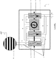
En référence à la
La cellule de puissance 22 comprend un sectionneur de tension 26 alimenté par le haut de la cellule via une alimentation électrique externe 27 (étant ici par exemple du 220V alternatif domestique). L'alimentation électrique externe peut-être de tous type connu de l'homme du métier, notamment par exemple du triphasé 3X400V, du monophasé 230V, du monophasé 110V... et pourrait entrer dans la cellule par n'importe quel côté. La cellule de puissance 22 comprend de plus un contacteur de puissance 28 permettant d'acheminer ou non la puissance vers la pompe 40 (sous commande d'une UGMC 31, principe détaillé par après), un relais thermique 29 afin de couper l'alimentation en puissance du contacteur 28 en cas d'échauffement, et un ensemble de disjoncteurs / interrupteurs différentiels 30 protégeant l'installation et les personnes contre les risques de surtension et d'électrisation.With reference to the
The
La cellule de gestion comprend une unité de gestion micro contrôlée (UGMC) 31 qui reçoit ici son alimentation électrique (interface « POWER ») en 24V alternatif d'un transformateur 32, ici de 220VAC vers 24VAC. L'alimentation de l'UGMC passe au préalable par un disjoncteur 33 protégeant l'UGMC des surtensions. Le transformateur 32 est lui-même alimenté depuis la cellule de puissance 22. Le transformateur 32 et le disjoncteur 33 pourraient également être placés dans la cellule de puissance 22 mais sont ici dans la cellule de gestion à proximité de l'UGMC pour clarté de lecture. L'UGMC 31 comprend un ensemble d'interfaces entrées-sorties (respectivement « INPUTS » et « OUTPUTS »). Ici, trois entrées analogiques et une sortie numérique sont schématisées. Chaque UGMC (et composants adjacents) ou module nécessaire dans le tableau correspond à une fonction (ici, une seule fonction : le circuit de chauffage). Par fonction il faut ici comprendre le terme précédemment détaillé en milieu de page 10 et exemplifié par le tableau N°1.
Les UGMC utilisées sont des UGMC de marques et modèles bien connus de l'homme du métier et sont standardisés pour chaque fonction. C'est-à-dire qu'en fonction de l'équipement à raccorder, certaines entrées-sorties peuvent ne pas être raccordées. Cela permet ainsi à l'homme du métier de travailler toujours avec les mêmes modules et participe à rendre le tableau électrique plus intuitif.
Les interfaces entrées de l'UGMC 31 sont respectivement connectées à des bornes 35' situés dans la cellule de raccordement 24' liée à la partie gestion du tableau. Les bornes 35' sont connectées à une sonde de température 36 de retour d'eau et une sonde de température 37 de départ d'eau, pour lesquelles l'UGMC 31 reçoit un retour d'information S sous forme d'un signal analogique. Les bornes 35' peuvent être étiquetés (ici XAI1, XAI2 et XAI3 pour bornier X, entrée analogique 1,2 et 3) et de couleurs correspondantes à leur fonction afin de rendre leur branchement plus intuitif. Les connexions d'alimentation des sondes ne sont pas représentées par souci de clarté mais sont évidentes pour un homme du métier.The management cell comprises a micro-controlled management unit (UGMC) 31 which here receives its electrical supply (“POWER” interface) at 24V AC from a
The UGMCs used are UGMCs of brands and models well known to those skilled in the art and are standardized for each function. In other words, depending on the equipment to be connected, some I / O may not be connected. This thus allows a person skilled in the art to always work with the same modules and helps to make the electrical panel more intuitive.
The input interfaces of the
En fonction du retour d'information S, l'UGMC 31 envoie un signal numérique, via la sortie numérique, à un relais 34, pour que celui-ci laisse passer, ou non, le signal 24VAC du transformateur 32 vers le contacteur 28 situé dans la cellule de puissance afin que celui-ci alimente à son tour, ou non, la pompe 40 en puissance (220VAC) via une borne 35 située dans la cellule de raccordement 24. Tous les composants de l'ensemble des cellules du tableau sont ici montés sur des rails 38. L'installation n'a pas été représentée avec l'entièreté des signaux de retours d'informations vers l'UGMC ou des signaux de commandes et d'alimentation des dispositifs de l'équipement dans un soucis de clarté. Il est possible par exemple que des vannes 42 en entrée et en sortie du circuit de chauffage 35 puissent être commandées par l'UGMC. De même, il également possible que des signaux d'information sur l'état du contacteur 28 et du relais thermique 29 retournent vers l'UGMC.Depending on the feedback S, the
En fonctionnement, les sondes de températures 36 et 37 de départ et de retour d'eau indiquent à l'UGMC 31 la température d'eau chaude 39 en entrée et d'eau froide 41 en sortie du circuit de chauffage 35. Sur base de ces informations, l'UGMC 31 détermine en fonction de sa programmation interne si la pompe 40 doit être activée ou désactivée, et le cas échéant, envoie un signal vers le contacteur de puissance 28 afin que ce dernier commute et respectivement transmette ou coupe l'arrivée en puissance vers la pompe 40. Par programmation interne, il faut comprendre les exigences de fonctionnement du circuit de chauffage 35 retransmises sous forme d'un programme informatique téléversé dans l'UGMC, par exemple à partir d'un poste de commande centralisé. Ainsi, l'arrivée en chaude dans le circuit de chauffage 35 par la pompe 40 est gérée par le tableau selon l'invention.In operation, the water flow and return
L'ensemble des composants électriques représentés ne sont pas exhaustifs et peuvent ne pas être présents, être présent dans une implémentation, ou en nombre différent, suivant les fonctions nécessaires. Ici, seule la fonction « circuit de chauffage » a été représentée mais d'autres fonctions pourraient se trouver également dans le tableau. On différencie alors sur cette base différents modèles de tableaux qui peuvent être regroupés en tableaux mono-fonction ou multifonctions. On pourrait notamment retrouver dans un tableau multifonctions, par exemple, la commande d'un second circuit de chauffage pour lequel une seconde UGMC serait alors ajouté dans la cellule de gestion 23, associés à d'autre composants de « courant for »t et de « courant faible », et qui permettrait la commande de ce second circuit de chauffage.All the electrical components shown are not exhaustive and may not be present, be present in an implementation, or in different numbers, depending on the functions. required. Here, only the "heating circuit" function has been shown, but other functions could also be found in the table. On this basis, different panel models are then differentiated which can be grouped into single-function or multi-function panels. One could in particular find in a multifunction panel, for example, the control of a second heating circuit for which a second UGMC would then be added in the
Par ailleurs, il n'est pas exclu que certains composants électriques particuliers qui pourraient être considérés comme gérant la puissance puissent se trouver dans la cellule de gestion, ou inversement, tant que le régime de courant fort se trouve dans la cellule de puissance et le régime de courant faible dans la cellule de gestion.
De plus, la disposition des cellules et des composants électriques à l'intérieur de celles-ci peut varier en fonction de l'installation. Il est par exemple possible que les cellules de raccordements 24 et 24' soient disposées en haut et en bas du tableau, tandis que les cellules de puissance 22 et de gestion 23 soient disposées à gauche et à droite du tableau.
De manière similaire, les bornes 35 et 35' peuvent être indépendamment disposées vers l'intérieur du tableau (i.e. dans la zone centrale vide située entre les 4 cellules du tableau), ou vers l'extérieur de celui-ci en fonction du branchement le plus commode pour l'homme du métier.
Les connexions entre les bornes 35, 35' et l'UGMC 31 sont ici chacune représentées par un câble effectuant directement la liaison entre ces derniers. Il est toutefois possible que les bornes 35 et 35' soient connectées à un bornier intermédiaire positionné (ici non représenté par soucis de clarté) sur un rail situé dans la logette de raccordement correspondante (respectivement 24 et 24') afin de rendre l'installation ou la fabrication du tableau plus facile et plus intuitive.In addition, it is not excluded that certain particular electrical components which could be considered as managing the power can be found in the management cell, or vice versa, as long as the high current regime is in the power cell and the low current regime in the management cell.
In addition, the arrangement of the cells and the electrical components inside them may vary depending on the installation. It is for example possible that the
Similarly, the
The connections between the
En référence à la
En référence aux
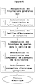
Tout d'abord, dans une première étape A, on demande au client les informations générales concernant l'installation électrique. Par exemple, on demande la localisation de l'installation (environnement extérieur, cave, locale électrique...), l'alimentation électrique disponible (3x400V + N, 220V monophasé...), le pouvoir de coupure de l'installation (6KA, 25KA, 36kA...), le matériau du tableau souhaité (métal, polycarbonate...), la qualité du projet souhaitée (certification LEED, BREAM, classification du bâtiment...) etc.
Dans une deuxième étape B, on sectionne virtuellement une première fois l'installation en identifiant et en catégorisant les équipements de l'installation par familles d'équipements à raccorder. Dans l'installation électrique de la
Dans une troisième étape C, on sectionne virtuellement une seconde fois l'installation électrique en identifiant et en catégorisant les équipements de chaque famille par fonctions des équipements à raccorder. De nouveau, dans l'installation de la
Dans une quatrième étape D on sélectionne les composants à implanter pour chaque fonction de gestion et on les agence de façon organisée dans la cellule de gestion du tableau électrique sous forme de modules. Ainsi, dans le tableau de la
Dans une étape E, on détermine les composants de transports de la puissance (ou énergie électrique) vers les équipements nécessaires au raccordement des équipements (en respectant notamment les normes de sécurité en vigueur), puis on les installe dans la cellule de puissance. Dans le tableau de la
Enfin, dans une dernière étape F, on établit les connexions électriques appropriées (comme détaillés précédemment pour la
First of all, in a first step A, the customer is asked for general information concerning the electrical installation. For example, we ask for the location of the installation (outdoor environment, cellar, electrical room, etc.), the available power supply (3x400V + N, 220V single-phase, etc.), the breaking capacity of the installation ( 6KA, 25KA, 36kA ...), the desired panel material (metal, polycarbonate ...), the quality of the desired project (LEED certification, BREAM, building classification ...) etc.
In a second step B, the installation is virtually sectioned for the first time by identifying and categorizing the equipment of the installation by families of equipment to connect. In the electrical installation of the
In a third step C, the electrical installation is virtually cut a second time by identifying and categorizing the equipment items of each family by function of the equipment to be connected. Again, in the installation of the
In a fourth step D, the components to be installed for each management function are selected and they are arranged in an organized manner in the management cell of the electrical panel in the form of modules. Thus, in the table of
In a step E, the components for transporting the power (or electrical energy) to the equipment necessary for connecting the equipment (in particular respecting the safety standards in force) are determined, then they are installed in the power cell. In the table of the
Finally, in a last step F, the appropriate electrical connections are established (as detailed previously for the
Toutes les étapes d'implémentation des composants et précâblage peuvent être faites en atelier, avant d'apporter le tableau électrique ainsi préparé sur son site de raccordement. Ce travail peut être hautement automatisé, sur base de schémas simple et donc confié à du personnel non qualifié. Il reste alors, sur site, uniquement à procéder aux raccordements finaux aux bornes de raccordement, sans avoir à intervenir à l'intérieur du tableau.All the stages of component implementation and pre-wiring can be done in the workshop, before bringing the electrical panel thus prepared to its connection site. This work can be highly automated, based on simple diagrams and therefore entrusted to unqualified personnel. All that remains, on site, is to make the final connections to the connection terminals, without having to intervene inside the switchboard.
Les étapes A jusqu'à E, avant l'installation des composants peut avantageusement se faire à l'aide d'un logiciel ou d'une application dédiée. Le logiciel peut être agencé pour proposer les composants en fonction des informations renseignées par un utilisateur. Par exemple, le logiciel ou l'application peut être associée à une interface posant à l'utilisateur des questions selon une séquence précise sur le contenu de l'installation électrique, les équipements à connecter, les distances entre les équipements ou des données métrique liées au plan de l'installation, ... L'utilisateur peut se voir offrir un choix sur les composants, par exemple un choix de marques ou de tarif. Le logiciel ou l'application peut être programmée pour déterminer le diamètre des câbles en fonction des puissances à gérer, le type de force motrice la mieux adaptée (FMDR et/ou FMDB), les couleurs des câbles à utiliser en fonction de l'emplacement des fonctions dans le tableau, les dimensions du tableau et son organisation, i.e., la répartition des composants dans les cellules. Le processus peut ainsi aboutir par exemple au dessin automatique du plan électrique de l'installation et/ou à un devis pour réaliser le(s) tableau(x).
En sortie du procédé informatisé, un opérateur peut se voir fournir la composition d'un tableau à monter, sur mesure. L'opérateur en question n'a alors besoin d'aucune compétence particulière en électricité et le montage peut se faire de façon industrielle. De la même façon qu'un conducteur peut configurer son véhicule en choisissant parmi une multitude d'option, un constructeur peut configurer le(s) tableau(x) électrique(s) de son installation et les faire fabriquer « en usine » ou en atelier » par un opérateur.Steps A to E, before installing the components, can advantageously be done using software or a dedicated application. The software can be arranged to offer the components according to the information entered by a user. For example, the software or the application can be associated with an interface asking the user questions according to a precise sequence on the content of the electrical installation, the equipment to be connected, the distances between the equipment or related metric data. in terms of installation, ... The user can be offered a choice of components, for example a choice of brands or prices. The software or the application can be programmed to determine the diameter of the cables according to the powers to be managed, the type of driving force best suited (FMDR and / or FMDB), the colors of the cables to be used according to the location functions in the table, the dimensions of the table and its organization, ie, the distribution of the components in the cells. The process can thus lead, for example, to the automatic drawing of the electrical plan of the installation and / or to an estimate for producing the panel (s).
At the end of the computerized process, an operator can be provided with the composition of a custom-made table to be assembled. The operator in question then does not need any particular skill in electricity and the assembly can be done industrially. In the same way that a driver can configure his vehicle by choosing from a multitude of options, a manufacturer can configure the electrical panel (s) of its installation and have them manufactured "in the factory" or in the workshop "by an operator.
L'invention a été expliquée pour un tableau électrique gérant uniquement un circuit de chauffage dans un bâtiment. Toutefois, l'invention ne se limite pas à la gestion d'un unique équipement, d'une unique fonction ou d'une unique famille et peut sur le même principe gérer une installation nettement plus complète. De même, le tableau de sectionnement de l'installation électrique en familles et en fonctions de la page 10 et 11 est présent à titre exemplatif et ne représente pas une version absolue et exhaustive du sectionnement possible de l'installation électrique d'un bâtiment. Il est notamment envisageable de regrouper les familles / fonctions différemment et d'ajouter d'autres familles / fonctions. Enfin, l'invention ne se limite pas à une installation électrique d'un bâtiment et il est concevable de transposer le principe et le tableau électrique décrit ici à tout type d'installation électrique.The invention has been explained for an electrical panel managing only a heating circuit in a building. However, the invention is not limited to the management of a single device, a single function or a single family and can on the same principle manage a much more complete installation. Likewise, the table for sectioning the electrical installation into families and functions on pages 10 and 11 is provided by way of example and does not represent an absolute and exhaustive version of the possible sectioning of the electrical installation of a building. In particular, it is possible to group the families / functions together differently and to add other families / functions. Finally, the invention is not limited to an electrical installation of a building and it is conceivable to transpose the principle and the electrical panel described here to any type of electrical installation.
L'invention a été illustrée dans un schéma de force motrice directe (FMDR), c'est-à-dire que chaque tableau comprend les composants de sécurité lui permettant de disjoncter (une protection par tableau). Cette configuration est particulièrement lorsque les fonctions sont localisées dans un espace confiné, comme par exemple un local technique, une centrale de traitement d'air, ... La force motrice des fonctions est distribuées directement sur les composants de terrain. Le signal de sécurité et réseau de communication sont distribué au sein du tableau électrique. Cette configuration permet jusqu'à 40% d'économie de longueur de câble.The invention has been illustrated in a direct motive force (FMDR) diagram, that is to say that each switchboard includes the safety components allowing it to trip (one protection per switchboard). This configuration is particularly when the functions are located in a confined space, such as for example a technical room, an air handling unit, etc. The driving force of the functions is distributed directly to the field components. The safety signal and communication network are distributed within the electrical panel. This configuration allows up to 40% savings in cable length.
Néanmoins, selon l'implantation du ou des tableaux, il est également envisageable de travailler en force motrice distribuée (FMDB), c'est à dire qu'un disjoncteur situé en amont de plusieurs tableaux raccordés en série. Cette implantation est particulièrement adaptée lorsque le projet permet de décentraliser les fonctions (puissance et gestion) à proximité des composant de terrains. Dans ce cas, plusieurs tableaux mono-fonction décentralisés sont protégés par un disjoncteur de tête situé dans la fonction maître du réseau de fonctions. Chaque réseau de fonctions doit au moins comprendre une UGMC décisionnel dans lequel sont installé, les éléments de gestion des sécurités, programme horaire... permettant également la communication vers les autres réseaux de fonctions. La force motrice, le signal de sécurité et le réseau de communication, est distribuée de manière sérielle. Cette configuration permet de limiter encore plus la longueur de câble par rapport à un branchement traditionnel, la longueur des câbles étant généralement réduite à 3 m ou moins, ce qui permet de réaliser une économie de câble allant jusque 60%.However, depending on the layout of the switchgear (s), it is also possible to envisage working with distributed motive power (FMDB), ie a circuit breaker located upstream of several switchboards connected in series. This implantation is particularly suitable when the project allows functions to be decentralized (power and management) close to land components. In this case, several decentralized single-function switchboards are protected by a head circuit breaker located in the master function of the function network. Each function network must at least include a decision-making UGMC in which the security management elements, time program, etc. are installed, also allowing communication to other function networks. The driving force, the safety signal and the communication network, is distributed serially. This configuration makes it possible to further limit the cable length compared to a traditional connection, the length of the cables being generally reduced to 3 m or less, which makes it possible to achieve a cable saving of up to 60%.
L'invention est donc non seulement relative aux tableaux multifonctions tels que décrits plus haut, mais également aux tableaux mono-fonction. Un tel tableau comprend généralement trois cellules uniquement : une cellule de puissance, une cellule de gestion ou commande et une cellule de raccordement.The invention therefore relates not only to multi-function panels as described above, but also to single-function panels. Such a table generally comprises only three cells: a power cell, a management or control cell and a connection cell.
Ce tableau dit mono-fonction est positionné au plus près de l'élément à gérer. Sa composition est généralement simple puisqu'il ne gère qu'une fonction et il peut avantageusement être fourni déjà équipé de tous ses composants, connectés électriquement de façon adéquate entre eux et aux bornes de la cellule de raccordement. L'installateur peut ainsi placer une série de tableaux pré-équipés, au plus près de l'équipement ou du circuit correspondant à la fonction à gérer.This so-called single-function table is positioned as close as possible to the element to be managed. Its composition is generally simple since it manages only one function and it can advantageously be supplied already equipped with all its components, electrically connected in an adequate manner to each other and to the terminals of the connection cell. The installer can thus place a series of pre-equipped panels, as close as possible to the equipment or circuit corresponding to the function to be managed.
Claims (15)
Priority Applications (5)
| Application Number | Priority Date | Filing Date | Title |
|---|---|---|---|
| EP20154385.7A EP3840142A1 (en) | 2020-01-29 | 2020-01-29 | Automation of the production of electrical switchboards through an identified process |
| BR112022014614A BR112022014614A2 (en) | 2020-01-29 | 2021-01-26 | AUTOMATION OF ELECTRICAL PANEL MANUFACTURING THROUGH AN IDENTIFIED PROCESS |
| CA3162332A CA3162332A1 (en) | 2020-01-29 | 2021-01-26 | Automation of the manufacturing of electrical panels through an identified process |
| US17/795,750 US20230075920A1 (en) | 2020-01-29 | 2021-01-26 | Automation of the manufacturing of electrical panels through an identified process |
| PCT/EP2021/051749 WO2021151887A1 (en) | 2020-01-29 | 2021-01-26 | Automation of the manufacturing of electrical panels through an identified process |
Applications Claiming Priority (1)
| Application Number | Priority Date | Filing Date | Title |
|---|---|---|---|
| EP20154385.7A EP3840142A1 (en) | 2020-01-29 | 2020-01-29 | Automation of the production of electrical switchboards through an identified process |
Publications (1)
| Publication Number | Publication Date |
|---|---|
| EP3840142A1 true EP3840142A1 (en) | 2021-06-23 |
Family
ID=69400461
Family Applications (1)
| Application Number | Title | Priority Date | Filing Date |
|---|---|---|---|
| EP20154385.7A Pending EP3840142A1 (en) | 2020-01-29 | 2020-01-29 | Automation of the production of electrical switchboards through an identified process |
Country Status (5)
| Country | Link |
|---|---|
| US (1) | US20230075920A1 (en) |
| EP (1) | EP3840142A1 (en) |
| BR (1) | BR112022014614A2 (en) |
| CA (1) | CA3162332A1 (en) |
| WO (1) | WO2021151887A1 (en) |
Citations (4)
| Publication number | Priority date | Publication date | Assignee | Title |
|---|---|---|---|---|
| JPH0541311U (en) * | 1991-10-30 | 1993-06-01 | 河村電器産業株式会社 | Double-sided door type electrical device storage box |
| US6107701A (en) * | 1998-08-24 | 2000-08-22 | Reliance Controls Corporation | Optional meter panel for a transfer switch having a terminal compartment |
| CN207250966U (en) * | 2017-08-23 | 2018-04-17 | 天津市中力神盾电子科技有限公司 | Power distribution cabinet |
| CN208015158U (en) * | 2018-04-20 | 2018-10-26 | 深圳市亚泰国际建设股份有限公司 | Integrated distribution box |
Family Cites Families (5)
| Publication number | Priority date | Publication date | Assignee | Title |
|---|---|---|---|---|
| FR2659505B1 (en) * | 1990-03-08 | 1992-05-29 | Merlin Gerin | LOW VOLTAGE TABLE. |
| DE4313654A1 (en) * | 1993-04-21 | 1994-10-27 | Siemens Ag | Metal-encapsulated medium-voltage switchgear panel with switch compartment, busbar compartment and cable connection compartment |
| FR2850799B1 (en) * | 2003-02-04 | 2006-03-10 | Integration Tech Et Cablage | CONNECTOR HOUSING FOR ELECTRICAL CABINET |
| DE102012220951B4 (en) * | 2012-11-16 | 2017-11-30 | Trumpf Werkzeugmaschinen Gmbh + Co. Kg | Mounting system for an electrical control cabinet, as well as control cabinet |
| WO2019192706A1 (en) * | 2018-04-05 | 2019-10-10 | Abb Schweiz Ag | Switch gear module for installation in a switch gear cabinet and switch gear cabinet including such a switch gear module |
-
2020
- 2020-01-29 EP EP20154385.7A patent/EP3840142A1/en active Pending
-
2021
- 2021-01-26 CA CA3162332A patent/CA3162332A1/en active Pending
- 2021-01-26 BR BR112022014614A patent/BR112022014614A2/en unknown
- 2021-01-26 WO PCT/EP2021/051749 patent/WO2021151887A1/en active Application Filing
- 2021-01-26 US US17/795,750 patent/US20230075920A1/en active Pending
Patent Citations (4)
| Publication number | Priority date | Publication date | Assignee | Title |
|---|---|---|---|---|
| JPH0541311U (en) * | 1991-10-30 | 1993-06-01 | 河村電器産業株式会社 | Double-sided door type electrical device storage box |
| US6107701A (en) * | 1998-08-24 | 2000-08-22 | Reliance Controls Corporation | Optional meter panel for a transfer switch having a terminal compartment |
| CN207250966U (en) * | 2017-08-23 | 2018-04-17 | 天津市中力神盾电子科技有限公司 | Power distribution cabinet |
| CN208015158U (en) * | 2018-04-20 | 2018-10-26 | 深圳市亚泰国际建设股份有限公司 | Integrated distribution box |
Also Published As
| Publication number | Publication date |
|---|---|
| US20230075920A1 (en) | 2023-03-09 |
| BR112022014614A2 (en) | 2022-09-13 |
| WO2021151887A1 (en) | 2021-08-05 |
| CA3162332A1 (en) | 2021-08-05 |
Similar Documents
| Publication | Publication Date | Title |
|---|---|---|
| Yu et al. | Techno-economic viability of silicon-based tandem photovoltaic modules in the United States | |
| Hernández-Callejo et al. | A review of photovoltaic systems: Design, operation and maintenance | |
| Braun et al. | Signal processing for solar array monitoring, fault detection, and optimization | |
| JP5480287B2 (en) | A system for controlling power from a solar array by selectively configuring connections between solar panels. | |
| TWI752123B (en) | Power distribution networks for electrochromic devices | |
| US20140314062A1 (en) | Aquatic-Based Automation Systems | |
| US20120112557A1 (en) | Solar Panel with Reconfigurable Interconnections | |
| KR20170093890A (en) | Multiple interacting systems at a site | |
| CA2764501A1 (en) | Smart grid over power line communication network | |
| US10097005B2 (en) | Self-configuring photo-voltaic panels | |
| WO2010136968A1 (en) | Apparatus and method for managing and conditioning photovoltaic power harvesting systems | |
| US20140277800A1 (en) | Power Management System For A Structure | |
| Martirano et al. | Building automation and control systems (bacs): a review | |
| EP2941521A1 (en) | Façade element, building comprising such an element and method for mounting a building facade | |
| EP3840142A1 (en) | Automation of the production of electrical switchboards through an identified process | |
| US10270254B2 (en) | Energy generation interconnection | |
| CN202275317U (en) | Remote monitoring maintenance system based on third generation (3G) and wind-light complementary power supply technology | |
| EP3216096B1 (en) | Electrical installation comprising an electrical panel and several electrical connection points | |
| EP2346140B1 (en) | Control and protection device for an electric facility | |
| EP2568788B1 (en) | Device and method for monitoring an electric apparatus or installation, electric installation comprising one such device | |
| EP2166189B1 (en) | Façade block comprising a support frame for a window, designed for installation in a building | |
| FR3002642A1 (en) | Measurement system i.e. bidirectional power meter unit, for measuring power and/or electrical energy consumed and/or produced on electric line of e.g. single-phase installation, has interface connected to Open Graph protocol | |
| Serhane et al. | Optimizing solar systems using DeviceNET | |
| Njoka et al. | Evaluation of IoT-based remote monitoring systems for stand-alone solar PV installations in Kenya | |
| EP3953875A1 (en) | Method for evaluating photovoltaic energy production and evaluation and management unit implementing the method |
Legal Events
| Date | Code | Title | Description |
|---|---|---|---|
| PUAI | Public reference made under article 153(3) epc to a published international application that has entered the european phase |
Free format text: ORIGINAL CODE: 0009012 |
|
| STAA | Information on the status of an ep patent application or granted ep patent |
Free format text: STATUS: THE APPLICATION HAS BEEN PUBLISHED |
|
| AK | Designated contracting states |
Kind code of ref document: A1 Designated state(s): AL AT BE BG CH CY CZ DE DK EE ES FI FR GB GR HR HU IE IS IT LI LT LU LV MC MK MT NL NO PL PT RO RS SE SI SK SM TR |
|
| STAA | Information on the status of an ep patent application or granted ep patent |
Free format text: STATUS: REQUEST FOR EXAMINATION WAS MADE |
|
| 17P | Request for examination filed |
Effective date: 20211222 |
|
| RAV | Requested validation state of the european patent: fee paid |
Extension state: MA Effective date: 20211222 |
|
| RBV | Designated contracting states (corrected) |
Designated state(s): AL AT BE BG CH CY CZ DE DK EE ES FI FR GB GR HR HU IE IS IT LI LT LU LV MC MK MT NL NO PL PT RO RS SE SI SK SM TR |
|
| RIN1 | Information on inventor provided before grant (corrected) |
Inventor name: BOGAERT, RENAUD Inventor name: AGOSTINI, VITTORIO |
|
| RAP3 | Party data changed (applicant data changed or rights of an application transferred) |
Owner name: OCCHILUPO, ANDREA Owner name: BOGAERT, PIERRE Owner name: BOGAERT, RENAUD Owner name: AGOSTINI, VITTORIO |
|
| REG | Reference to a national code |
Ref country code: HK Ref legal event code: DE Ref document number: 40055459 Country of ref document: HK |
|
| STAA | Information on the status of an ep patent application or granted ep patent |
Free format text: STATUS: EXAMINATION IS IN PROGRESS |
|
| 17Q | First examination report despatched |
Effective date: 20230428 |
|
| P01 | Opt-out of the competence of the unified patent court (upc) registered |
Effective date: 20230428 |