EP2346140B1 - Kontroll- und Schutzvorrichtung für eine elektrische Anlage - Google Patents
Kontroll- und Schutzvorrichtung für eine elektrische Anlage Download PDFInfo
- Publication number
- EP2346140B1 EP2346140B1 EP10354089.4A EP10354089A EP2346140B1 EP 2346140 B1 EP2346140 B1 EP 2346140B1 EP 10354089 A EP10354089 A EP 10354089A EP 2346140 B1 EP2346140 B1 EP 2346140B1
- Authority
- EP
- European Patent Office
- Prior art keywords
- control
- output
- module
- inputs
- outputs
- Prior art date
- Legal status (The legal status is an assumption and is not a legal conclusion. Google has not performed a legal analysis and makes no representation as to the accuracy of the status listed.)
- Active
Links
- 239000012636 effector Substances 0.000 claims description 25
- 238000004378 air conditioning Methods 0.000 claims description 15
- 238000009434 installation Methods 0.000 claims description 13
- 238000009826 distribution Methods 0.000 claims description 11
- 238000012545 processing Methods 0.000 claims description 8
- 238000004891 communication Methods 0.000 claims description 5
- 238000010616 electrical installation Methods 0.000 claims description 5
- 238000012544 monitoring process Methods 0.000 claims description 3
- 238000012806 monitoring device Methods 0.000 claims 1
- 238000005265 energy consumption Methods 0.000 description 4
- 238000005516 engineering process Methods 0.000 description 4
- 238000000034 method Methods 0.000 description 4
- 230000003068 static effect Effects 0.000 description 4
- 230000004913 activation Effects 0.000 description 3
- 238000012423 maintenance Methods 0.000 description 3
- 238000005259 measurement Methods 0.000 description 3
- 201000004569 Blindness Diseases 0.000 description 2
- 230000008033 biological extinction Effects 0.000 description 2
- 238000013461 design Methods 0.000 description 2
- 238000012986 modification Methods 0.000 description 2
- 230000004048 modification Effects 0.000 description 2
- 238000011144 upstream manufacturing Methods 0.000 description 2
- 230000003213 activating effect Effects 0.000 description 1
- 230000005540 biological transmission Effects 0.000 description 1
- 239000003795 chemical substances by application Substances 0.000 description 1
- 230000003247 decreasing effect Effects 0.000 description 1
- 230000001419 dependent effect Effects 0.000 description 1
- 238000001514 detection method Methods 0.000 description 1
- 230000000694 effects Effects 0.000 description 1
- 238000010438 heat treatment Methods 0.000 description 1
- 230000010365 information processing Effects 0.000 description 1
- 238000009413 insulation Methods 0.000 description 1
- 238000002955 isolation Methods 0.000 description 1
- 238000004519 manufacturing process Methods 0.000 description 1
- 238000005457 optimization Methods 0.000 description 1
- 230000008569 process Effects 0.000 description 1
- 230000000750 progressive effect Effects 0.000 description 1
- 230000008521 reorganization Effects 0.000 description 1
- 230000011664 signaling Effects 0.000 description 1
- 238000000638 solvent extraction Methods 0.000 description 1
- 238000003860 storage Methods 0.000 description 1
- 238000012546 transfer Methods 0.000 description 1
- 230000001960 triggered effect Effects 0.000 description 1
- 230000002747 voluntary effect Effects 0.000 description 1
Images


Classifications
-
- H—ELECTRICITY
- H02—GENERATION; CONVERSION OR DISTRIBUTION OF ELECTRIC POWER
- H02H—EMERGENCY PROTECTIVE CIRCUIT ARRANGEMENTS
- H02H7/00—Emergency protective circuit arrangements specially adapted for specific types of electric machines or apparatus or for sectionalised protection of cable or line systems, and effecting automatic switching in the event of an undesired change from normal working conditions
- H02H7/26—Sectionalised protection of cable or line systems, e.g. for disconnecting a section on which a short-circuit, earth fault, or arc discharge has occured
- H02H7/261—Sectionalised protection of cable or line systems, e.g. for disconnecting a section on which a short-circuit, earth fault, or arc discharge has occured involving signal transmission between at least two stations
-
- H—ELECTRICITY
- H02—GENERATION; CONVERSION OR DISTRIBUTION OF ELECTRIC POWER
- H02J—CIRCUIT ARRANGEMENTS OR SYSTEMS FOR SUPPLYING OR DISTRIBUTING ELECTRIC POWER; SYSTEMS FOR STORING ELECTRIC ENERGY
- H02J2310/00—The network for supplying or distributing electric power characterised by its spatial reach or by the load
- H02J2310/10—The network having a local or delimited stationary reach
- H02J2310/12—The local stationary network supplying a household or a building
- H02J2310/14—The load or loads being home appliances
-
- Y—GENERAL TAGGING OF NEW TECHNOLOGICAL DEVELOPMENTS; GENERAL TAGGING OF CROSS-SECTIONAL TECHNOLOGIES SPANNING OVER SEVERAL SECTIONS OF THE IPC; TECHNICAL SUBJECTS COVERED BY FORMER USPC CROSS-REFERENCE ART COLLECTIONS [XRACs] AND DIGESTS
- Y02—TECHNOLOGIES OR APPLICATIONS FOR MITIGATION OR ADAPTATION AGAINST CLIMATE CHANGE
- Y02B—CLIMATE CHANGE MITIGATION TECHNOLOGIES RELATED TO BUILDINGS, e.g. HOUSING, HOUSE APPLIANCES OR RELATED END-USER APPLICATIONS
- Y02B70/00—Technologies for an efficient end-user side electric power management and consumption
- Y02B70/30—Systems integrating technologies related to power network operation and communication or information technologies for improving the carbon footprint of the management of residential or tertiary loads, i.e. smart grids as climate change mitigation technology in the buildings sector, including also the last stages of power distribution and the control, monitoring or operating management systems at local level
- Y02B70/3225—Demand response systems, e.g. load shedding, peak shaving
-
- Y—GENERAL TAGGING OF NEW TECHNOLOGICAL DEVELOPMENTS; GENERAL TAGGING OF CROSS-SECTIONAL TECHNOLOGIES SPANNING OVER SEVERAL SECTIONS OF THE IPC; TECHNICAL SUBJECTS COVERED BY FORMER USPC CROSS-REFERENCE ART COLLECTIONS [XRACs] AND DIGESTS
- Y04—INFORMATION OR COMMUNICATION TECHNOLOGIES HAVING AN IMPACT ON OTHER TECHNOLOGY AREAS
- Y04S—SYSTEMS INTEGRATING TECHNOLOGIES RELATED TO POWER NETWORK OPERATION, COMMUNICATION OR INFORMATION TECHNOLOGIES FOR IMPROVING THE ELECTRICAL POWER GENERATION, TRANSMISSION, DISTRIBUTION, MANAGEMENT OR USAGE, i.e. SMART GRIDS
- Y04S20/00—Management or operation of end-user stationary applications or the last stages of power distribution; Controlling, monitoring or operating thereof
- Y04S20/20—End-user application control systems
- Y04S20/222—Demand response systems, e.g. load shedding, peak shaving
-
- Y—GENERAL TAGGING OF NEW TECHNOLOGICAL DEVELOPMENTS; GENERAL TAGGING OF CROSS-SECTIONAL TECHNOLOGIES SPANNING OVER SEVERAL SECTIONS OF THE IPC; TECHNICAL SUBJECTS COVERED BY FORMER USPC CROSS-REFERENCE ART COLLECTIONS [XRACs] AND DIGESTS
- Y04—INFORMATION OR COMMUNICATION TECHNOLOGIES HAVING AN IMPACT ON OTHER TECHNOLOGY AREAS
- Y04S—SYSTEMS INTEGRATING TECHNOLOGIES RELATED TO POWER NETWORK OPERATION, COMMUNICATION OR INFORMATION TECHNOLOGIES FOR IMPROVING THE ELECTRICAL POWER GENERATION, TRANSMISSION, DISTRIBUTION, MANAGEMENT OR USAGE, i.e. SMART GRIDS
- Y04S20/00—Management or operation of end-user stationary applications or the last stages of power distribution; Controlling, monitoring or operating thereof
- Y04S20/20—End-user application control systems
- Y04S20/242—Home appliances
Definitions
- the invention relates to a control device and electrical protection programmed by default and reconfigurable centrally, for controlling and individually protect groups of power effectors of different natures; each of the effectors may further be associated with a control receiving device and / or a sensor type control device. More particularly, the invention relates to a distribution device, control and protection comprising a plurality of modules each able to control at least three types of outputs, a portion of the control being preprogrammed.
- Control modules allowing control of one or more high-power effectors placed remotely in an intervention space may comprise very low voltage control interfaces, that is to say at alternative voltages of less than 50 V or continuous below 120 V, values defined in the French standard NF C 15-100. This type of device privileging the safety of the user can be used in applications related to public or residential establishments.
- control modules comprising several multi-command interfaces in an intervention platform
- the control interfaces generally require a switch and a cable connecting said interface to the effector.
- the complexity comes from the number of cables to be implemented, the number of interconnections to be made and the inherent risks of wiring errors. Complexity is further increased for points multiple control of an effector (of type remote control or back and forth) and / or the progressive control (dimmer type or " dimmer ").
- each cable can only perform a control function, and therefore drive only one effector.
- a module associated with control devices sends orders to several effectors. These multiple commands, however, do not allow a complete and personalized setup of an installation, all effectors changing state at the same time: see for example FR 2,688,951 .
- the invention aims to overcome the drawbacks of existing devices, and proposes a device for centralized control of a set spaces in which a default programming is associated with an optimization of the necessary connections so that the implementation of the device is easy.
- the invention relates to a device for distributing and controlling an electrical installation, preferably comprising protection functions.
- the electrical installation for example an intervention zone of a building, can be separated into a plurality of entities, preferably from two to four office-type spaces, each entity being provided with a plurality of effectors.
- power of different type including lighting, air conditioning and window shadowing, and a plurality of control receivers, in particular a switch and a button for actuating the occultation; advantageously, sensors for detecting presence, brightness, or other functions of comfort and efficiency, such as the CO 2 content are further provided in each entity for control.
- the device according to the invention is housed in a housing on which are identified parts relating to each of the entities of the installation, and corresponding to modules of the device according to the invention so as to simplify the implementation of the device.
- Each module thus comprises a number of inputs corresponding to the number of control receivers and sensors of each entity, a number of outputs corresponding to the number of effectors of an entity, the said outputs being of a different type, and control means premises for transmitting a signal for each output.
- at least the second inputs connected to the sensors are associated with means for processing their signals specific to each module.
- each output is further associated with static protection means against short circuits at the load; to avoid any wiring problem, it is desirable that the outputs are associated with connectors of different types.
- the device further comprises centralized control means connected to each module via the output control means, as well as possibly the input signal processing means.
- the central control means are programmed by default, and adapted so that the output signals of each module depend on a program of said means, depending on the signals of the inputs connected to the sensors of said module, and react in priority to the signals of the first inputs connected to the control receivers associated therewith.
- the command is carried out via a DALI-type bus ( "Digital Addressable Lighting Interface ") connected in parallel to each module: this option makes it possible to identify the connector of connection ; moreover, in the presence of the static switching means of each output, the centralized control means are advantageously provided so that the addressing according to the DALI protocol is automatic.
- the centralized control means also comprise communication means making it possible to modify their programming, for example an ethernet port or a communication bus, the control device according to the invention being for example connected to a global monitoring network .
- the centralized control means are further adapted to allow a grouping of a plurality of modules so that a control input signal at a module of the group causes the same output signal for all the modules of said group.
- each module of the device according to the invention is provided with an interface, for example a push button, for activating a grouping at the level of configuration means acting directly on the program of the centralized control means.
- the configuration means can be modified only after voluntary activation, for example by means of an activation button of the housing of the control device.
- the device according to the invention is further adapted for electrical distribution within the controlled entities.
- the device thus comprises a supply input, preferably provided with circuit-breaker and / or disconnector-type protection means, and a number of distribution lines corresponding to the number of outputs of each module, so as to supply each type separately. effector.
- means for measuring the energy consumption are provided, in particular at the level of the supply inlet for the overall consumption, and at the level of the particularly consuming outlets, such as lighting or air conditioning, on the supply lines. concerned.
- an operating zone 1 can be divided into four intervention areas 5 i .
- Each space 5, for example an office comprises at least three types of power effectors intended to operate jointly a load of different type, including the lighting 10, heating and / or air conditioning means 20, means of occultation 30 such as blinds or electric shutters.
- all the operating zones 1 of the building can be connected to a central building supervision network 40; preferably, the control of the air conditioning is centralized at this network 40 and not accessible to the user, while the other two effectors 10, 30 can be operated manually via control receivers, including a switch 50 , eventually equipped with dimmer means and a push button 60.
- the power effectors 10, 20, 30 operate at alternating voltages, and can be controlled by very low voltage control receivers 50, 60.
- the control device 100 is preferably placed in such a way as to optimize the wiring distances to each of the spaces 5 i , in particular in the false ceiling of the operating zone 1.
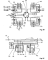
- the centralized control / control device 100 thus comprises an input 102 for its power supply and distributing power to a number of outputs 110, 120, 130 adapted to the number of effectors 10, 20, 30, in particular four times three; in particular, as will become clear later, the outputs of the same type are fed by the same line of their own, and the device 100 comprises three lines 102 10 , 102 20 , 102 30 in parallel.
- the control device 100 comprises central protection means 104 at the power supply input 102, for example a disconnecting block and / or an electromechanical protection circuit breaker.
- each of the outputs 110, 120, 130 is further associated with an additional personal protection device 106; preferably, the individual protection device 106 is electronic, and made by the combination of transistors and current measuring means and insulation, as for example described in WO 2009/124818 , which guarantees optimum protection for each of the lines. What's more, this choice of a static electronic switching technology provides unparalleled selectivity and therefore continuity of service, only the faulty output being triggered. Moreover, this type of protection can be rearmed remotely, by actuating a receiver that can be part of the device 100 according to the invention, or by order from the central control and supervision network 40.
- the control device 100 is provided with means 140 for determining the overall power consumption of the operating area 1, and comprises a current measuring circuit 142 at the power input.
- differentiated measurement means are provided to enable analyzes of the consumption, so as to possibly modify the uses.
- the device 100 according to the invention comprises, on their respective line 102 10 , 102 20 , measuring means 144, 146 of the consumption for two types of output 110, 120, such as lighting and air conditioning.
- the device 100 may then include means 148 for processing data relating to the energy consumption, for example a printed circuit board; alternatively, this data can be transmitted directly to the central supervisory network 40.
- the device 100 is adapted for the control of each of the effectors 10, 20, 30, these being grouped together by intervention zone 5.
- the process of setting up It is easy to install, including a default programming built into the system and an intuitive cable connection.
- the device 100 preferred according to the invention comprises four control modules 150 i , each provided with three types of outputs 110 i, 120; 130 i to each type of effector 10, 20, 30; preferably (see also figure 3 ), the modules 150 i are clearly identified on the face of the housing of the control device 100.
- the control is performed according to a centralized programming, but also following local input signals.
- manual control receivers 50, 60 may be actuated to modify certain outputs 110, 130; for example, only two of the commands 110, 130, and not the air-conditioning 20, are accessible by an external input that can be actuated by a user, and each control module 150 comprises an input 210, 230 intended for these types of output 110, 130 and connected to the control receivers 50, 60.
- the inputs and outputs of the same type are associated, for example by being identified by pictograms on the housing of the control device 100, and / or located face to face or parallel on two different levels ( figure 3 ).
- each module 150 of the device 100 also comprises at least one input 240 for local external parameters, which are provided via appropriate sensors.
- a light sensor and a presence sensor 80 in the intervention space 5 provide their information to a mu-parameter input 240A; a sensor 90 informs a second input 240B of the closure or not of the window of said space 5, ...
- the different sensors 80, 90 provide a signal to processing means 250, for example a microprocessor; advantageously, the control receivers 50, 60 are also directly connected to the processing means 250.
- the signals of the inputs 210, 230, 240, once processed, are then transferred to the control means 260, 270, 280 of each output 110, 120, 130 of the corresponding module 150; the transfer is performed via centralized control means of the device 100 according to the invention, for example a microprocessor 300, allowing optimal management of the operating area 1.
- the central means 300 can be autonomous and / or connected to the network 40 building supervision by means of communication 310 adapted, for example according to a protocol selected by a fieldbus 310A, and / or ethernet 310B by the TCP / IP protocol.
- the central means 300 coordinate and manage all the functionalities of the device 100 according to the invention, and thus ensure the energy efficiency in the area concerned 1; advantageously, the processing card 148 of the data relating to the energy consumption is included in the centralized control means 300.
- the centralized control means 300 are programmed by default appropriately. For example, it can be provided: an extinction of the lights 10 if the presence sensor 80 provides a negative signal for more than 15 minutes; a gradual control providing a constant minimum level of 350 lux during the day; automatic blindness of windows if the light exceeds 1000 lux; an air conditioning ban if the adapted sensor 90 detects that a window is open;
- the installation of the control device 100 according to the invention is therefore facilitated: the connection of the cables is intuitive in each of the modules 150 clearly identified ( figure 3 ); a default programming then immediately allows appropriate control of the effectors 10, 20, 30 connected, via the control receivers 50, 60, possibly respecting, if necessary, instructions from the monitoring network 40 and / or control means centralized 300.
- the actuation of the blind 30 and / or the light 10 is achieved by wireless technology or battery-free, by means of self-powered switches 50, 60 radiofrequency type for easy maintenance and a greater flexibility; the device 100 according to the invention is preferably provided with a radiofrequency transmission / reception card 320.
- the sensors 80, 90 can be connected by any means, by wired inputs, possibly of different types according to the invention.
- the information is binary 240B, or multiple in which case a 240A RJ11 type of connection can be provided, or even via a wireless module, for example via the radiofrequency card 320.
- the control 230 of the occultation output 130 is coupled to a phase inversion function, so that the output is a four-point connector, which is clearly distinguishable from the three-point connection of the air conditioning control 120, performed by a single power supply output, the control being performed by an external controller, specific to each air conditioning system, itself connected to the central control and supervision network 40.
- the control air conditioning can also be performed by the control device 100 according to the invention, with a PWM type modulation to effectively control valves and a multiple speed control for a fan coil.
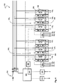
- the light control 110 is carried out via the DALI protocol ( "Digital Addressable Lighting Interface ") in order to better manage the lighting, the connectors adapted to this protocol (5 points ) then allowing direct identification.
- the addressing of the devices 10 relating to the light control is preferably done automatically thanks to the presence of the static protection devices 106 on each start 110.
- the device 100 according to the invention includes a DALI 330 controller on a 335 bus common to all four modules 150 and therefore all the outputs of lighting type 110, in parallel with the power supply 102 10 .
- each output 110 i is individually and alternatively fed via centralized means 300 and individual control means 260 i which enable the switching device 106 to be switched on.
- the lighting outputs 110 i , i ⁇ 1 of three modules 150 i , i ⁇ 1 are disconnected, and all the components connected to the output 110 1 powered are scanned and associated in groups according to the DALI protocol, which assigns them to each one address allowing the common control of all the lights connected to the module 150 1 .
- the centralized means 300 are adapted to be reprogrammed, in particular by the presence of a programming interface, for example via the communication means 310B, which can allow a modification of the initial parameterization in case of modification of the use of the device 100 according to the invention without requiring its redesign.
- a programming interface for example via the communication means 310B
- an energy efficiency algorithm can be implemented to arbitrate between different loads when excessive consumption is determined.
- the configuration can be modified directly on the building supervisory network 40 via the fieldbus interface 310A and its appropriate programming tools.
- the device 100 according to the invention is also provided with means for grouping the intervention spaces 5, for example in case of reorganization of the operating zone 1.
- the installer to signal the device.
- 100 according to the invention that two or three of the modules 150 or all four, in fact relate to a single environment, for example an "open space" type of arrangement ( figure 1 ).
- the device 100 according to the invention is provided with local configuration means 340 for associating the modules 150 i so that the centralized means 300 send the same control commands for the groups of modules 150 i concerned.
- the configuration means 340 may comprise a specific mode implemented in the central means 300, a push-button type interface 342 enabling the activation of this mode, advantageously coupled to a signaling interface 344, for example a light emitting diode. and a pushbutton 346 i per module 150 i .
- a signaling interface 344 for example a light emitting diode.
- a pushbutton 346 i per module 150 i .
- the user uses the configuration means 340 via the button 342, then successively presses the buttons 346 1 , 346 2 , 346 3 .
- a lighting control 210 i , i 1 to 3 on a single receiver 50 of the three spaces, and therefore only one of the three control modules 150 1 , 150 2, 150 3 will activate all the lighting outputs 10 of all the spaces 5 1, 5 2, 5 3; alternatively for automatic shutdown, it will be necessary for the three presence detectors 80 to signal an absence so that the control means 300 trigger the extinction.
- the device 100 is designed so that the man / machine interface is the most user-friendly.
- an indicator system 350 for example composed of light-emitting diodes, is provided for checking on each module 150 the correct operation and the correct wiring; in particular, one or two buttons 352 per output 110, 210, 310 make it possible to simulate the actuation of said output, and an associated light emitting diode 354 makes it possible to validate the wiring.
- the various functions are performed by a device 100 of simple design, limiting the cable length through a shared upstream power supply 102 and a control connection point 210, 230, 240 near the installation location of the sensors 80, 90 and receivers 40, 50, and reducing the time required for its installation.
- the solution according to the invention effectively couples the functions of electrical distribution and automation, in particular by being able to provide a building control system 40 with all data on measurement, protection and status of outputs in a native format.
- the ability to control, individually or on a mesh of spaces 5 i grouped, the loads and to obtain the relative information makes it possible to optimize the energy consumption of the buildings by a control / end order.
- the device 100 according to the invention offers an optimal compromise between ease of installation and variety of settings, this with reduced hardware and implementation costs.
- the specialization of the inputs / outputs by type of application with the boarding of the specificities concerning their control / control, makes it possible to facilitate the connection of the device according to the invention; pre-configuration and automatic addressing allow easy setup.
- the preceding device 100 has an optimized range of functions, it is possible thanks to the design of its outputs 210, 230, 240, to use the previous device 100, provided with four modules 150 with four inputs and three outputs, in another configuration.
- the number of modules can be adjusted to the practice of the building, with for example operating areas 1 comprising two, six spaces, or more; the number of inputs / outputs per module 150 can be decreased or increased depending on the number of individual entities to be managed on the platform 1 of offices, with for example an additional application to computer means, or an increased number of sensors.
- the type of sensor can be adapted, just as the nature of the outputs ...; other features, such as the presence of charge detection, can be added.
Claims (10)
- Verteilungs- und Kontrollvorrichtung (100) für eine elektrische Anlage (1), wobei die Anlage (1) eine erste Anzahl von Einheiten (5) umfasst, wobei jede Einheit (5) mit einer zweiten Anzahl von Leistungseffektoren (10, 20, 30) unterschiedlicher Typen versehen ist, wobei die Vorrichtung (100) umfasst:- einen Versorgungseingang (102) und eine zweite Anzahl von elektrischen Leistungsverteilungsleitungen (10210, 10220, 10230);- eine erste Anzahl von Modulen (150), wobei jedes Modul (150) umfasst:- eine zweite Anzahl von Ausgängen (110, 120, 130) unterschiedlichen Typs, die sich an die Effektoren (10, 20, 30) anschließen können, wobei jeder Ausgangstyp von einer unterschiedlichen Verteilungsleitung (102j) versorgt wird,- lokale Steuermittel (260, 270, 280), die jedem Ausgang (110, 120, 130) zugeordnet sind, um die Effektoren (10, 20, 30) individuell zu steuern, und- eine dritte Anzahl von Eingängen (210, 230, 240), umfassend eine Vielzahl von ersten Eingängen, die an einem Empfänger (50, 60) zur direkten Steuerung für eine Vielzahl von Ausgängen (110, 130) angeschlossen werden können, und mindestens einen zweiten Eingang, der an Kontrollmittel (80, 90) angeschlossen werden kann;- Mittel (300) zur zentralisierten Steuerung, die dazu vorgesehen sind, dass die Ausgangssignale (110, 120, 130) jedes Moduls (150) direkt von den Signalen der ersten Eingänge (210, 230) des Moduls (150) abhängen, und dass die Ausgangssignale (110, 120, 130) jedes Moduls (150) bei Nichtvorhandensein der ersten Eingänge (210, 230) von einem Programm der Steuermittel (300) und den Signalen der zweiten Eingänge des Moduls (150) abhängen;- Konfigurationsmittel (340) im Bereich der zentralisierten Steuermittel (300), umfassend eine Konfigurationsschnittstelle (346i), die jedem Modul (150i) zugeordnet ist, so dass die Betätigung einer Vielzahl von Schnittstellen (346) zu einer einzigen Steuerung für die Ausgänge der entsprechenden Vielzahl von Modulen (150) führt.
- Vorrichtung (100) nach Anspruch 1, ferner umfassend statische Schutzmittel (106) für jeden Ausgang (110, 120, 130) der Vorrichtung (100).
- Vorrichtung (100) nach einem der vorhergehenden Ansprüche, ferner umfassend eine Schutzvorrichtung (104) am Versorgungseingang (102).
- Vorrichtung (100) nach einem der vorhergehenden Ansprüche, ferner umfassend einen Bus (335) vom Typ DALI, der parallel mit einem ersten Ausgang (110) jedes Moduls (150i) verbunden ist.
- Vorrichtung (100) nach einem der vorhergehenden Ansprüche, bei dem jedes Modul (150) ferner Signalbearbeitungsmittel (250) mindestens der zweiten Eingänge (240) umfasst.
- Vorrichtung (100) nach einem der vorhergehenden Ansprüche, ferner umfassend Mittel (140) zum Messen des elektrischen Verbrauchs einer Vielzahl von Ausgängen.
- Vorrichtung (100) nach einem der vorhergehenden Ansprüche, ferner umfassend Kommunikationsmittel (310, 320), die es ermöglichen, das Programm der zentralisierten Steuermittel (300) zu modifizieren.
- Vorrichtung (100) nach einem der vorhergehenden Ansprüche, umfassend ein Gehäuse, bei dem eine erste Anzahl von getrennten Teilen identifiziert werden kann, wobei jedes Teil alle Elemente in Zusammenhang mit einem Modul (150) umfasst, insbesondere die Ausgangsstecker und die Konfigurationsaktuatoren (346).
- Vorrichtung (100) nach einem der vorhergehenden Ansprüche, umfassend vier Module (150) mit jeweils mindestens drei Typen von unterschiedlichen Ausgängen und vier Eingängen.
- Vorrichtung (100) nach einem der vorhergehenden Ansprüche, bei der ein erster Ausgangstyp (110) an die Beleuchtung angeschlossen werden kann, ein zweiter Ausgangstyp (120) an die Klimatisierung (20) angeschlossen werden kann, ein dritter Ausgangstyp an Verdunkelungsmittel (30) angeschlossen werden kann, und bei der die ersten Eingänge (210, 230) mit den ersten und zweiten Ausgangstypen (110, 130) in Zusammenhang stehen, und die zweiten Eingänge an Sensoren (80, 90) angeschlossen sind.
Applications Claiming Priority (1)
| Application Number | Priority Date | Filing Date | Title |
|---|---|---|---|
| FR1000148A FR2955431B1 (fr) | 2010-01-15 | 2010-01-15 | Dispositif de controle et de protection pour une installation electrique |
Publications (3)
| Publication Number | Publication Date |
|---|---|
| EP2346140A2 EP2346140A2 (de) | 2011-07-20 |
| EP2346140A3 EP2346140A3 (de) | 2014-04-02 |
| EP2346140B1 true EP2346140B1 (de) | 2015-09-09 |
Family
ID=42646270
Family Applications (1)
| Application Number | Title | Priority Date | Filing Date |
|---|---|---|---|
| EP10354089.4A Active EP2346140B1 (de) | 2010-01-15 | 2010-12-13 | Kontroll- und Schutzvorrichtung für eine elektrische Anlage |
Country Status (3)
| Country | Link |
|---|---|
| EP (1) | EP2346140B1 (de) |
| CN (1) | CN102156458B (de) |
| FR (1) | FR2955431B1 (de) |
Families Citing this family (3)
| Publication number | Priority date | Publication date | Assignee | Title |
|---|---|---|---|---|
| FR2992011B1 (fr) * | 2012-06-15 | 2015-01-23 | Jean Louis Baal | Assemblage des lots techniques et architecturaux |
| FR2993991B1 (fr) * | 2012-07-30 | 2014-08-08 | Hager Electro Sas | Systeme de mesure de la consommation electrique d'appareils modulaires dans un coffret |
| ES2470466B1 (es) * | 2012-12-19 | 2015-04-13 | Charles ZAMORA MOLINA | Dispositivo de control domótico |
Family Cites Families (9)
| Publication number | Priority date | Publication date | Assignee | Title |
|---|---|---|---|---|
| US5170310A (en) * | 1990-11-29 | 1992-12-08 | Square D Company | Fail-resistant solid state interruption system |
| FR2688951B1 (fr) * | 1992-03-19 | 1997-04-04 | Merlin Gerin | Dispositif et installation de distribution electrique terminale. |
| FR2693323B1 (fr) * | 1992-07-01 | 1994-09-02 | Merlin Gerin | Installation de distribution d'énergie électrique avec structure de communication domotique. |
| FR2770014B1 (fr) * | 1997-10-20 | 2000-03-10 | Schneider Electric Sa | Procede de commande pour une installation electrique comportant des modules communiquants, dispositif et installation mettant en oeuvre un tel procede |
| DE10032646A1 (de) * | 2000-07-05 | 2002-01-17 | Abb Patent Gmbh | Gebäudeinstallationssystem und Installationsgerät |
| US6909942B2 (en) * | 2002-02-25 | 2005-06-21 | General Electric Company | Method for power distribution system components identification, characterization and rating |
| EP1702366A1 (de) | 2003-12-05 | 2006-09-20 | STMicroelectronics S.A. | Aktive halbleiterkomponente mit kleiner oberfläche |
| ITPR20070079A1 (it) * | 2007-10-22 | 2009-04-23 | Mahtechs S P A | Unita a ridondanza elettromeccanica per la gestione di carichi elettrici di vario tipo ed amperaggio |
| FR2930091B1 (fr) | 2008-04-09 | 2011-10-28 | Schneider Electric Ind Sas | Systeme a relais statique comprenant deux transistors de type jfet en serie |
-
2010
- 2010-01-15 FR FR1000148A patent/FR2955431B1/fr not_active Expired - Fee Related
- 2010-12-13 EP EP10354089.4A patent/EP2346140B1/de active Active
-
2011
- 2011-01-17 CN CN201110008703.5A patent/CN102156458B/zh active Active
Also Published As
| Publication number | Publication date |
|---|---|
| FR2955431A1 (fr) | 2011-07-22 |
| CN102156458A (zh) | 2011-08-17 |
| EP2346140A2 (de) | 2011-07-20 |
| FR2955431B1 (fr) | 2011-12-23 |
| CN102156458B (zh) | 2014-09-10 |
| EP2346140A3 (de) | 2014-04-02 |
Similar Documents
| Publication | Publication Date | Title |
|---|---|---|
| EP0923185B1 (de) | Elektrische Unterbrechungsvorrichtung mit einem Kommunikationsmodul | |
| EP1798840A1 (de) | Modulares intelligentes steuersystem und verbindung für eine haus-steuerinstallation | |
| EP3132593B1 (de) | Steuerung von intelligenten angetriebenen vorrichtungen | |
| EP2346140B1 (de) | Kontroll- und Schutzvorrichtung für eine elektrische Anlage | |
| CN106687872B (zh) | 用于配置建筑物自动化系统的方法 | |
| EP3258326B1 (de) | Automatisiertes steuerungssystem für wohngebäude | |
| EP1376279A1 (de) | Sicherheitsübertragungssystem | |
| EP3216096B1 (de) | Elektrische installation bestehend aus einer elektrischen schalttafel und mehreren elektrischen anschlusspunkten | |
| EP0495322B1 (de) | Elektrisches Kontroll- und Steuerungssystem einer Funktionseinheit, insbesondere eines Hauses eines Gebäudes, eines Schiffes oder dergleichen | |
| US20160299515A1 (en) | Unitary telematic system for space management, with a universal general purpose | |
| EP3588461B1 (de) | Steuersystem von verbundenen objekten, entsprechendes steuerverfahren und computerprogramm | |
| US20170317844A1 (en) | Multi-networked lighting device | |
| EP2461442B1 (de) | Steuergruppe für Steuerzeichen und Verfahren zum Steuern der besagten Gruppe | |
| EP2648488A1 (de) | LED-Beleuchtung und Kontrollverfahren einer elektrischen Anlage, die eine solche Beleuchtung umfasst | |
| FR3017008A1 (fr) | Installation de commande permettant de commander l'alimentation electrique d'une pluralite d'organes electriques en courant continu | |
| EP3364300B1 (de) | Verfahren zum kontrollieren einer haustechnikanlage, entsprechende ausstattung und entsprechende anlage | |
| Ahmed et al. | Automatic control of home appliances based on SCADA and IoT system | |
| EP3718253A1 (de) | System zur elektrischen verwaltung einer vielzahl von elektrischen lasten | |
| EP0911777B1 (de) | Steuerverfahren für Elektroinstallation mit kommunizierenden Modulen, Vorrichtung und Installation zur Ausführung des Verfahrens | |
| FR3012582A1 (fr) | Organe de pilotage et ensemble de tels organes de pilotage | |
| EP3140962B1 (de) | System zur verwaltung einer struktur mit einer box mit redundanten verbindungen | |
| EP3840142A1 (de) | Automatisierung der herstellung von elektrischen schalttafeln mithilfe eines identifizierten prozesses | |
| EP3712083A1 (de) | Elektrisches system mit einer tragbaren hülle, die an die verpackung und den transport von mindestens einem mikromodul zur steuerung elektrischer ladungen angepasst ist, und pairing-bank | |
| EP3764751A2 (de) | Strassenbeleuchtung für eine zentralisierte steuerung, und entsprechendes steuerungsverfahren | |
| FR3126479A3 (fr) | Ensemble de contrôle de climatisation zonée par le biais de conduits d'air ou d'eau avec des thermostats radio |
Legal Events
| Date | Code | Title | Description |
|---|---|---|---|
| PUAI | Public reference made under article 153(3) epc to a published international application that has entered the european phase |
Free format text: ORIGINAL CODE: 0009012 |
|
| AK | Designated contracting states |
Kind code of ref document: A2 Designated state(s): AL AT BE BG CH CY CZ DE DK EE ES FI FR GB GR HR HU IE IS IT LI LT LU LV MC MK MT NL NO PL PT RO RS SE SI SK SM TR |
|
| AX | Request for extension of the european patent |
Extension state: BA ME |
|
| REG | Reference to a national code |
Ref country code: DE Ref legal event code: R079 Ref document number: 602010027340 Country of ref document: DE Free format text: PREVIOUS MAIN CLASS: H02J0013000000 Ipc: H02J0001000000 |
|
| PUAL | Search report despatched |
Free format text: ORIGINAL CODE: 0009013 |
|
| AK | Designated contracting states |
Kind code of ref document: A3 Designated state(s): AL AT BE BG CH CY CZ DE DK EE ES FI FR GB GR HR HU IE IS IT LI LT LU LV MC MK MT NL NO PL PT RO RS SE SI SK SM TR |
|
| AX | Request for extension of the european patent |
Extension state: BA ME |
|
| RIC1 | Information provided on ipc code assigned before grant |
Ipc: H02J 3/00 20060101ALI20140224BHEP Ipc: H02J 1/00 20060101AFI20140224BHEP Ipc: H02J 4/00 20060101ALI20140224BHEP Ipc: H02J 13/00 20060101ALI20140224BHEP Ipc: H02H 7/22 20060101ALI20140224BHEP Ipc: H02J 3/14 20060101ALI20140224BHEP Ipc: H02H 7/26 20060101ALI20140224BHEP |
|
| 17P | Request for examination filed |
Effective date: 20141124 |
|
| RBV | Designated contracting states (corrected) |
Designated state(s): AL AT BE BG CH CY CZ DE DK EE ES FI FR GB GR HR HU IE IS IT LI LT LU LV MC MK MT NL NO PL PT RO RS SE SI SK SM TR |
|
| GRAP | Despatch of communication of intention to grant a patent |
Free format text: ORIGINAL CODE: EPIDOSNIGR1 |
|
| INTG | Intention to grant announced |
Effective date: 20150519 |
|
| GRAS | Grant fee paid |
Free format text: ORIGINAL CODE: EPIDOSNIGR3 |
|
| GRAA | (expected) grant |
Free format text: ORIGINAL CODE: 0009210 |
|
| AK | Designated contracting states |
Kind code of ref document: B1 Designated state(s): AL AT BE BG CH CY CZ DE DK EE ES FI FR GB GR HR HU IE IS IT LI LT LU LV MC MK MT NL NO PL PT RO RS SE SI SK SM TR |
|
| REG | Reference to a national code |
Ref country code: GB Ref legal event code: FG4D Free format text: NOT ENGLISH |
|
| REG | Reference to a national code |
Ref country code: AT Ref legal event code: REF Ref document number: 748837 Country of ref document: AT Kind code of ref document: T Effective date: 20150915 Ref country code: CH Ref legal event code: EP |
|
| REG | Reference to a national code |
Ref country code: IE Ref legal event code: FG4D Free format text: LANGUAGE OF EP DOCUMENT: FRENCH |
|
| REG | Reference to a national code |
Ref country code: DE Ref legal event code: R096 Ref document number: 602010027340 Country of ref document: DE |
|
| REG | Reference to a national code |
Ref country code: FR Ref legal event code: PLFP Year of fee payment: 6 |
|
| REG | Reference to a national code |
Ref country code: NL Ref legal event code: MP Effective date: 20150909 |
|
| PG25 | Lapsed in a contracting state [announced via postgrant information from national office to epo] |
Ref country code: GR Free format text: LAPSE BECAUSE OF FAILURE TO SUBMIT A TRANSLATION OF THE DESCRIPTION OR TO PAY THE FEE WITHIN THE PRESCRIBED TIME-LIMIT Effective date: 20151210 Ref country code: FI Free format text: LAPSE BECAUSE OF FAILURE TO SUBMIT A TRANSLATION OF THE DESCRIPTION OR TO PAY THE FEE WITHIN THE PRESCRIBED TIME-LIMIT Effective date: 20150909 Ref country code: NO Free format text: LAPSE BECAUSE OF FAILURE TO SUBMIT A TRANSLATION OF THE DESCRIPTION OR TO PAY THE FEE WITHIN THE PRESCRIBED TIME-LIMIT Effective date: 20151209 Ref country code: LV Free format text: LAPSE BECAUSE OF FAILURE TO SUBMIT A TRANSLATION OF THE DESCRIPTION OR TO PAY THE FEE WITHIN THE PRESCRIBED TIME-LIMIT Effective date: 20150909 Ref country code: LT Free format text: LAPSE BECAUSE OF FAILURE TO SUBMIT A TRANSLATION OF THE DESCRIPTION OR TO PAY THE FEE WITHIN THE PRESCRIBED TIME-LIMIT Effective date: 20150909 |
|
| REG | Reference to a national code |
Ref country code: LT Ref legal event code: MG4D |
|
| REG | Reference to a national code |
Ref country code: AT Ref legal event code: MK05 Ref document number: 748837 Country of ref document: AT Kind code of ref document: T Effective date: 20150909 |
|
| PG25 | Lapsed in a contracting state [announced via postgrant information from national office to epo] |
Ref country code: RS Free format text: LAPSE BECAUSE OF FAILURE TO SUBMIT A TRANSLATION OF THE DESCRIPTION OR TO PAY THE FEE WITHIN THE PRESCRIBED TIME-LIMIT Effective date: 20150909 Ref country code: SE Free format text: LAPSE BECAUSE OF FAILURE TO SUBMIT A TRANSLATION OF THE DESCRIPTION OR TO PAY THE FEE WITHIN THE PRESCRIBED TIME-LIMIT Effective date: 20150909 Ref country code: HR Free format text: LAPSE BECAUSE OF FAILURE TO SUBMIT A TRANSLATION OF THE DESCRIPTION OR TO PAY THE FEE WITHIN THE PRESCRIBED TIME-LIMIT Effective date: 20150909 Ref country code: ES Free format text: LAPSE BECAUSE OF FAILURE TO SUBMIT A TRANSLATION OF THE DESCRIPTION OR TO PAY THE FEE WITHIN THE PRESCRIBED TIME-LIMIT Effective date: 20150909 |
|
| PG25 | Lapsed in a contracting state [announced via postgrant information from national office to epo] |
Ref country code: NL Free format text: LAPSE BECAUSE OF FAILURE TO SUBMIT A TRANSLATION OF THE DESCRIPTION OR TO PAY THE FEE WITHIN THE PRESCRIBED TIME-LIMIT Effective date: 20150909 |
|
| PG25 | Lapsed in a contracting state [announced via postgrant information from national office to epo] |
Ref country code: IT Free format text: LAPSE BECAUSE OF FAILURE TO SUBMIT A TRANSLATION OF THE DESCRIPTION OR TO PAY THE FEE WITHIN THE PRESCRIBED TIME-LIMIT Effective date: 20150909 Ref country code: EE Free format text: LAPSE BECAUSE OF FAILURE TO SUBMIT A TRANSLATION OF THE DESCRIPTION OR TO PAY THE FEE WITHIN THE PRESCRIBED TIME-LIMIT Effective date: 20150909 Ref country code: CZ Free format text: LAPSE BECAUSE OF FAILURE TO SUBMIT A TRANSLATION OF THE DESCRIPTION OR TO PAY THE FEE WITHIN THE PRESCRIBED TIME-LIMIT Effective date: 20150909 Ref country code: SK Free format text: LAPSE BECAUSE OF FAILURE TO SUBMIT A TRANSLATION OF THE DESCRIPTION OR TO PAY THE FEE WITHIN THE PRESCRIBED TIME-LIMIT Effective date: 20150909 Ref country code: IS Free format text: LAPSE BECAUSE OF FAILURE TO SUBMIT A TRANSLATION OF THE DESCRIPTION OR TO PAY THE FEE WITHIN THE PRESCRIBED TIME-LIMIT Effective date: 20160109 |
|
| PG25 | Lapsed in a contracting state [announced via postgrant information from national office to epo] |
Ref country code: BE Free format text: LAPSE BECAUSE OF NON-PAYMENT OF DUE FEES Effective date: 20151231 Ref country code: PL Free format text: LAPSE BECAUSE OF FAILURE TO SUBMIT A TRANSLATION OF THE DESCRIPTION OR TO PAY THE FEE WITHIN THE PRESCRIBED TIME-LIMIT Effective date: 20150909 Ref country code: PT Free format text: LAPSE BECAUSE OF FAILURE TO SUBMIT A TRANSLATION OF THE DESCRIPTION OR TO PAY THE FEE WITHIN THE PRESCRIBED TIME-LIMIT Effective date: 20160111 Ref country code: RO Free format text: LAPSE BECAUSE OF FAILURE TO SUBMIT A TRANSLATION OF THE DESCRIPTION OR TO PAY THE FEE WITHIN THE PRESCRIBED TIME-LIMIT Effective date: 20150909 Ref country code: AT Free format text: LAPSE BECAUSE OF FAILURE TO SUBMIT A TRANSLATION OF THE DESCRIPTION OR TO PAY THE FEE WITHIN THE PRESCRIBED TIME-LIMIT Effective date: 20150909 |
|
| REG | Reference to a national code |
Ref country code: DE Ref legal event code: R097 Ref document number: 602010027340 Country of ref document: DE |
|
| PLBE | No opposition filed within time limit |
Free format text: ORIGINAL CODE: 0009261 |
|
| STAA | Information on the status of an ep patent application or granted ep patent |
Free format text: STATUS: NO OPPOSITION FILED WITHIN TIME LIMIT |
|
| PG25 | Lapsed in a contracting state [announced via postgrant information from national office to epo] |
Ref country code: LU Free format text: LAPSE BECAUSE OF FAILURE TO SUBMIT A TRANSLATION OF THE DESCRIPTION OR TO PAY THE FEE WITHIN THE PRESCRIBED TIME-LIMIT Effective date: 20151213 Ref country code: MC Free format text: LAPSE BECAUSE OF FAILURE TO SUBMIT A TRANSLATION OF THE DESCRIPTION OR TO PAY THE FEE WITHIN THE PRESCRIBED TIME-LIMIT Effective date: 20150909 |
|
| REG | Reference to a national code |
Ref country code: CH Ref legal event code: PL |
|
| 26N | No opposition filed |
Effective date: 20160610 |
|
| GBPC | Gb: european patent ceased through non-payment of renewal fee |
Effective date: 20151213 |
|
| PG25 | Lapsed in a contracting state [announced via postgrant information from national office to epo] |
Ref country code: DK Free format text: LAPSE BECAUSE OF FAILURE TO SUBMIT A TRANSLATION OF THE DESCRIPTION OR TO PAY THE FEE WITHIN THE PRESCRIBED TIME-LIMIT Effective date: 20150909 Ref country code: SI Free format text: LAPSE BECAUSE OF FAILURE TO SUBMIT A TRANSLATION OF THE DESCRIPTION OR TO PAY THE FEE WITHIN THE PRESCRIBED TIME-LIMIT Effective date: 20150909 |
|
| REG | Reference to a national code |
Ref country code: IE Ref legal event code: MM4A |
|
| PG25 | Lapsed in a contracting state [announced via postgrant information from national office to epo] |
Ref country code: GB Free format text: LAPSE BECAUSE OF NON-PAYMENT OF DUE FEES Effective date: 20151213 Ref country code: CH Free format text: LAPSE BECAUSE OF NON-PAYMENT OF DUE FEES Effective date: 20151231 Ref country code: IE Free format text: LAPSE BECAUSE OF NON-PAYMENT OF DUE FEES Effective date: 20151213 Ref country code: LI Free format text: LAPSE BECAUSE OF NON-PAYMENT OF DUE FEES Effective date: 20151231 |
|
| REG | Reference to a national code |
Ref country code: FR Ref legal event code: PLFP Year of fee payment: 7 |
|
| PG25 | Lapsed in a contracting state [announced via postgrant information from national office to epo] |
Ref country code: SM Free format text: LAPSE BECAUSE OF FAILURE TO SUBMIT A TRANSLATION OF THE DESCRIPTION OR TO PAY THE FEE WITHIN THE PRESCRIBED TIME-LIMIT Effective date: 20150909 Ref country code: BG Free format text: LAPSE BECAUSE OF FAILURE TO SUBMIT A TRANSLATION OF THE DESCRIPTION OR TO PAY THE FEE WITHIN THE PRESCRIBED TIME-LIMIT Effective date: 20150909 Ref country code: HU Free format text: LAPSE BECAUSE OF FAILURE TO SUBMIT A TRANSLATION OF THE DESCRIPTION OR TO PAY THE FEE WITHIN THE PRESCRIBED TIME-LIMIT; INVALID AB INITIO Effective date: 20101213 |
|
| PG25 | Lapsed in a contracting state [announced via postgrant information from national office to epo] |
Ref country code: CY Free format text: LAPSE BECAUSE OF FAILURE TO SUBMIT A TRANSLATION OF THE DESCRIPTION OR TO PAY THE FEE WITHIN THE PRESCRIBED TIME-LIMIT Effective date: 20150909 |
|
| PG25 | Lapsed in a contracting state [announced via postgrant information from national office to epo] |
Ref country code: TR Free format text: LAPSE BECAUSE OF FAILURE TO SUBMIT A TRANSLATION OF THE DESCRIPTION OR TO PAY THE FEE WITHIN THE PRESCRIBED TIME-LIMIT Effective date: 20150909 Ref country code: MT Free format text: LAPSE BECAUSE OF FAILURE TO SUBMIT A TRANSLATION OF THE DESCRIPTION OR TO PAY THE FEE WITHIN THE PRESCRIBED TIME-LIMIT Effective date: 20150909 |
|
| REG | Reference to a national code |
Ref country code: FR Ref legal event code: PLFP Year of fee payment: 8 |
|
| PG25 | Lapsed in a contracting state [announced via postgrant information from national office to epo] |
Ref country code: MK Free format text: LAPSE BECAUSE OF FAILURE TO SUBMIT A TRANSLATION OF THE DESCRIPTION OR TO PAY THE FEE WITHIN THE PRESCRIBED TIME-LIMIT Effective date: 20150909 |
|
| PG25 | Lapsed in a contracting state [announced via postgrant information from national office to epo] |
Ref country code: AL Free format text: LAPSE BECAUSE OF FAILURE TO SUBMIT A TRANSLATION OF THE DESCRIPTION OR TO PAY THE FEE WITHIN THE PRESCRIBED TIME-LIMIT Effective date: 20150909 |
|
| PGFP | Annual fee paid to national office [announced via postgrant information from national office to epo] |
Ref country code: FR Payment date: 20231226 Year of fee payment: 14 |
|
| PGFP | Annual fee paid to national office [announced via postgrant information from national office to epo] |
Ref country code: DE Payment date: 20231227 Year of fee payment: 14 |