EP3588461B1 - Steuersystem von verbundenen objekten, entsprechendes steuerverfahren und computerprogramm - Google Patents
Steuersystem von verbundenen objekten, entsprechendes steuerverfahren und computerprogramm Download PDFInfo
- Publication number
- EP3588461B1 EP3588461B1 EP19176817.5A EP19176817A EP3588461B1 EP 3588461 B1 EP3588461 B1 EP 3588461B1 EP 19176817 A EP19176817 A EP 19176817A EP 3588461 B1 EP3588461 B1 EP 3588461B1
- Authority
- EP
- European Patent Office
- Prior art keywords
- connected object
- switch
- control device
- communication module
- command
- Prior art date
- Legal status (The legal status is an assumption and is not a legal conclusion. Google has not performed a legal analysis and makes no representation as to the accuracy of the status listed.)
- Active
Links
- 238000000034 method Methods 0.000 title claims description 11
- 238000004590 computer program Methods 0.000 title claims description 6
- 238000004891 communication Methods 0.000 claims description 83
- 230000008859 change Effects 0.000 claims description 38
- 238000001514 detection method Methods 0.000 claims description 20
- 238000012544 monitoring process Methods 0.000 claims description 4
- 238000013519 translation Methods 0.000 claims description 4
- 230000000694 effects Effects 0.000 claims description 3
- 230000015654 memory Effects 0.000 description 5
- 230000008901 benefit Effects 0.000 description 4
- 238000010616 electrical installation Methods 0.000 description 4
- 238000009434 installation Methods 0.000 description 4
- 230000005540 biological transmission Effects 0.000 description 3
- 230000005611 electricity Effects 0.000 description 3
- 238000010438 heat treatment Methods 0.000 description 2
- 238000003780 insertion Methods 0.000 description 2
- 230000037431 insertion Effects 0.000 description 2
- 238000005457 optimization Methods 0.000 description 2
- 238000012545 processing Methods 0.000 description 2
- 230000011514 reflex Effects 0.000 description 2
- 238000004378 air conditioning Methods 0.000 description 1
- 238000013459 approach Methods 0.000 description 1
- 238000012550 audit Methods 0.000 description 1
- 230000008033 biological extinction Effects 0.000 description 1
- 238000010586 diagram Methods 0.000 description 1
- 229940082150 encore Drugs 0.000 description 1
- 230000003203 everyday effect Effects 0.000 description 1
- 230000006870 function Effects 0.000 description 1
- 239000011521 glass Substances 0.000 description 1
- 230000010354 integration Effects 0.000 description 1
- 238000007726 management method Methods 0.000 description 1
- 230000007246 mechanism Effects 0.000 description 1
- 230000008569 process Effects 0.000 description 1
Images


Classifications
-
- G—PHYSICS
- G08—SIGNALLING
- G08C—TRANSMISSION SYSTEMS FOR MEASURED VALUES, CONTROL OR SIMILAR SIGNALS
- G08C17/00—Arrangements for transmitting signals characterised by the use of a wireless electrical link
- G08C17/02—Arrangements for transmitting signals characterised by the use of a wireless electrical link using a radio link
-
- H—ELECTRICITY
- H01—ELECTRIC ELEMENTS
- H01H—ELECTRIC SWITCHES; RELAYS; SELECTORS; EMERGENCY PROTECTIVE DEVICES
- H01H89/00—Combinations of two or more different basic types of electric switches, relays, selectors and emergency protective devices, not covered by any single one of the other main groups of this subclass
-
- H—ELECTRICITY
- H04—ELECTRIC COMMUNICATION TECHNIQUE
- H04L—TRANSMISSION OF DIGITAL INFORMATION, e.g. TELEGRAPHIC COMMUNICATION
- H04L12/00—Data switching networks
- H04L12/28—Data switching networks characterised by path configuration, e.g. LAN [Local Area Networks] or WAN [Wide Area Networks]
- H04L12/2803—Home automation networks
- H04L12/2816—Controlling appliance services of a home automation network by calling their functionalities
- H04L12/2818—Controlling appliance services of a home automation network by calling their functionalities from a device located outside both the home and the home network
-
- H—ELECTRICITY
- H05—ELECTRIC TECHNIQUES NOT OTHERWISE PROVIDED FOR
- H05B—ELECTRIC HEATING; ELECTRIC LIGHT SOURCES NOT OTHERWISE PROVIDED FOR; CIRCUIT ARRANGEMENTS FOR ELECTRIC LIGHT SOURCES, IN GENERAL
- H05B47/00—Circuit arrangements for operating light sources in general, i.e. where the type of light source is not relevant
- H05B47/10—Controlling the light source
- H05B47/175—Controlling the light source by remote control
- H05B47/19—Controlling the light source by remote control via wireless transmission
-
- H—ELECTRICITY
- H04—ELECTRIC COMMUNICATION TECHNIQUE
- H04L—TRANSMISSION OF DIGITAL INFORMATION, e.g. TELEGRAPHIC COMMUNICATION
- H04L12/00—Data switching networks
- H04L12/28—Data switching networks characterised by path configuration, e.g. LAN [Local Area Networks] or WAN [Wide Area Networks]
- H04L12/2803—Home automation networks
- H04L2012/284—Home automation networks characterised by the type of medium used
- H04L2012/2841—Wireless
-
- H—ELECTRICITY
- H04—ELECTRIC COMMUNICATION TECHNIQUE
- H04L—TRANSMISSION OF DIGITAL INFORMATION, e.g. TELEGRAPHIC COMMUNICATION
- H04L12/00—Data switching networks
- H04L12/28—Data switching networks characterised by path configuration, e.g. LAN [Local Area Networks] or WAN [Wide Area Networks]
- H04L12/2803—Home automation networks
- H04L2012/2847—Home automation networks characterised by the type of home appliance used
- H04L2012/285—Generic home appliances, e.g. refrigerators
Definitions
- the field of the invention is that of connected objects, such as for example connected light bulbs, temperature sensors, connected refrigerators or even connected sockets.
- connected object is meant here, and throughout the rest of this document, an electronic object connected wirelessly and sharing information with a computer, an electronic tablet, a mobile phone or another device, such as a gateway. access to a local communication network for example. More generally, a connected object is a real world device (watch, bulb, thermometer, boiler, etc.) capable of directly or indirectly exchanging information and data with the Internet network.
- a connected object is a real world device (watch, bulb, thermometer, boiler, etc.) capable of directly or indirectly exchanging information and data with the Internet network.
- the invention relates to the control of such connected objects, in particular, but not exclusively, within the framework of their domestic use, for example within a home.
- the typical example is that of the connected bulb.
- This can be controlled, for example, by means of a smart phone via a wireless communication protocol (such as Bluetooth® or Wifi®), which allows the color of the light diffused to be modified, the light intensity to be modulated, or more simply to order its switching on or off.
- a wireless communication protocol such as Bluetooth® or Wifi®
- Its installation is simple: just install the connected bulb in a ceiling light or a lamp and to switch it on, if necessary by actuating a switch electrically connected to the ceiling light or to the lamp.
- one of the drawbacks of this installation is that the actuation of the switch may prove to be incompatible with the remote control of the bulb connected by control equipment of the smart phone or tablet type. Indeed, if the user, when leaving his living room, turns off the bulb by flipping the associated switch to the open position, it is then no longer possible for him to relight the bulb by remote control using his smartphone. » As long as he has not flipped the associated switch to the closed position again, so as to ensure the power supply of the connected bulb.
- the document US 2004/164621 A1 describes a plug-in mechanism, for wireless remote control of an object, comprising a manual control panel, which can be mounted on a wall, and a plug-in unit.
- the use of the switch can prove to be troublesome, or even incompatible with the remote control of objects connected by smart phone or tablet.
- the primary function of the switch namely controlling the switching on or off of the connected bulb, is now obsolete, insofar as, on the one hand, the bulb must always be powered on to be remotely controllable via control equipment, and where, on the other hand, it is impossible to turn on, from a remote control equipment, a connected bulb previously extinguished by means of a switch .
- connected objects have a wide variety of communication languages, which are often proprietary communication languages, specific to the manufacturer of the connected object.
- the invention responds to this need by providing a system for controlling at least one connected object by means of a switch able to switch from an open position to a closed position, and vice versa.
- such a control system comprises a control device mounted in parallel with the switch in an electrical supply circuit of the connected object (s), and such a control device comprises a module detection of a change in position of the switch and a communication module capable of transmitting information relating to the change of position detected to the connected object (s).
- the invention is based on an entirely new and inventive approach to the control of connected objects supplied by an electrical supply circuit, for example within a home.
- the invention proposes to isolate in a very simple way the switch from the connected object (s), by mounting in parallel with the switch a control device in the electrical supply circuit of this or these connected object (s). Thanks to this parallel connection, the connected object (s) always remain powered on and therefore always connected and can therefore be controlled remotely by control equipment which can be a telephone. intelligent "smartphone" type, or a tablet for example.
- control device comprises a detection module capable of detecting the change in position of the switch and a communication module capable of subsequently transmitting information relating to this change of position detected to the object (s). logged in.
- such a communication module is able to receive a command intended for one or more connected object (s) coming from a remote control device and to transmit the command to this or these object (s) ( s) connected after possible translation of the command into a communication language suitable for this or these connected object (s).
- the communication module of the control device is able to control the connected object, not only from the commands resulting from the change of position of the switch, but also from commands received from a remote control equipment. smart phone type.
- such a communication module advantageously integrates the various communication protocols specific to each of the connected objects and can act as a translation portal between the control languages of the various remote control equipment items and those of the object (s). ) connected.
- the communication module is also able to transmit the information relating to the change of position detected to at least one other connected object.
- the switch intended initially to control one or more connected object (s) in particular can be reprogrammed in order to control one or more other connected object (s).
- control device thanks to its communication module, is capable of transmitting the change in position of the switch to one or more connected object (s) different from those initially planned.
- the user can decide that the switch placed in the entrance to his home will no longer be used to control the lighting of the entrance, but rather the exterior lighting of the porch.
- This gives great modularity and great flexibility in reconfiguring the home's electrical network, without any intervention by a professional electrician.
- the switch is no longer intended to control one or more connected object (s) located at a particular location in the home, but can be reprogrammed to control one or more object (s). connected (s) located elsewhere in the home. It thus becomes very easy to change the layout of your home and to adapt the control by switch of connected objects according to your habits.
- such a communication module is also able to transmit the information relating to the change of position detected to a device for monitoring human activity, which may for example be a local or remote server accessible. via a residential gateway.
- the information relating to the change in position of the switch, detected by the detection module of the control device can advantageously be transmitted by the communication module to a “tracking” or monitoring server: the detection change of position of the switch indicates in fact a human presence in the house, and moreover makes it possible to locate this human presence with precision.
- This tracking server can be a local or remote server, accessible via a residential gateway, which can be implemented as part of an anti-intrusion surveillance system, or of a parental control system for example.
- various data on the use of connected objects can be collected such as, for example, the type of connected object used, the times and schedules of use or again the location of the connected object in the home.
- the data collected make it possible to determine a profile of use of these connected objects by one or more users, for example who is present at a given time in the home and whether this presence is usual and normal at such a time or not.
- the communication module of the control device transmits to a device for monitoring human activity information relating to the switching on and / or switching off of one or more connected light bulbs. It is therefore possible to know whether someone is present in the home and, if so, where, for example in the garage or in a room. It is therefore possible, by grouping together the data of the schedule, time and place of use of connected bulbs, to know who is present, but also to anticipate the presence of a particular user.
- the collection of this data on the use of connected objects makes it possible to offer users a schedule for using these objects according to their habits and their needs. It is therefore possible for example to propose to anticipate the arrival of a user by switching on certain connected objects in particular, at a given time.
- such a communication module is able to transmit the information relating to the change of position detected to the connected object (s) through an access gateway to a local communication network. , also called residential gateway, to which the connected object (s) are connected.
- the communication module does not directly transmit the control command (received from a remote control device, or generated on detection of a change in the position of the switch) to the connected object, but transmits it to a residential or domestic gateway of the local communication network to which the connected object is connected. It is then the residential gateway which relays this command to the connected object (for example in Wi-Fi 2.4).
- such a control device also comprises means for interrupting the electrical supply circuit of the connected object (s), which are actuated when the detection module detects a change in position of the device. the switch to an open position and / or when the communication module receives a command to switch off the connected object (s) from a remote control device.
- the control device can thus integrate a switch arranged on the electrical supply circuit of the connected object, which can control the passage of current in the electrical supply circuit of the connected object (s).
- the control device switch can be opened, and interrupt the flow of electric current to the connected object, when the control device detects that the user has flipped the wall switch to the "OFF" position, and / or when 'it receives a command to switch off the connected object from a remote control device.
- control device thanks to its means of interrupting the electrical supply circuit of the connected object (s), allows an optimization of the electrical consumption within the dwelling.
- the invention also relates to a computer program product comprising program code instructions for implementing the steps of the aforementioned control method, when it is executed by a processor.
- the general principle of the invention is based on the insertion, into the power supply circuit of a connected object, of a control device, mounted in parallel with a control switch of the connected object, which allows , not only to ensure that the connected object is kept under permanent electrical voltage, whatever the position of the switch, but also to control the connected object to control its operation.
- control device allows a simple reconfiguration of the electrical supply circuit of one or more connected object (s), by isolating it (s) from the switch responsible for opening and / or the closing of their electrical supply circuit.
- a power supply circuit 8 of one or more connected object (s) 2 such as for example a connected bulb of the LiFx® type, or even Philips Hue®, or connected sockets such as SmartPlug®, or Wemo®.
- one or more connected object (s) 2 is / are connected to the electrical panel 4 through an electrical supply circuit 8.
- an electrical supply circuit 8 For the sake of simplicity, only one connected object 2 is illustrated in the figures below -after.
- a switch 1 able to switch from a closed position, illustrated in figure 1A , in an open position, shown in figure 1B , and conversely, controls the connected object 2 by interrupting or allowing the passage of electric current in the supply circuit 8 of the connected object 2.
- the switch 1 is used to control the switching on or off of the connected object, but also, for example, in the case of a connected bulb, to vary the color of the lighting or to modulate its light intensity.
- the connected object 2 When switch 1 is in the closed position, as shown in figure 1A , the connected object 2 is powered and can thus be controlled more finely by means of a remote control device 3, for example a smart phone or a tablet.
- This remote control device 3 controls the connected object by transmitting a 3.1 command, which can be conveyed by a wireless connection such as Wifi®, Bluetooth® or even Zigbee® or a wired connection of the line powerline type ( or CPL).
- the command transmitted by the remote control equipment 3 to the connected object 2 may relate, for example, to switching on and / or switching off, or even switching on different modes of use of the connected object 2.
- a connected bulb thanks to his smart phone 3, it is possible to remotely control the switching on and / or switching off of the bulb, but also the change of color of the bulb, or a decrease / increase in the light intensity thereof.
- the figure 1B illustrates the case where switch 1 is open, interrupting the flow of electric current in supply circuit 8 of connected object 2.
- Connected object 2 is no longer under voltage and consequently, can no longer be controlled by the remote control equipment 3 via a control 3.1. This situation poses a problem and lacks ergonomics for the user.
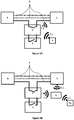
- the figure 1C illustrates a particular case in which the switch 1 is open, interrupting the flow of electric current in the supply circuit 8 of the connected object 2.
- the object connected 2 is no longer under voltage and consequently can no longer be controlled by remote control equipment, comprising, in this example, a TEL smart phone, a residential gateway 6 and a manufacturer gateway 7.
- the TEL smart phone sends a command 3.1 intended for one or more object (s) connected to the residential gateway 6 which receives and transmits this command to the manufacturer gateway 7.
- the manufacturer gateway 7 receives and transmits the command by translating it into a communication language specific to the connected object 2.
- the connected object 2 is not powered on, so it cannot execute the command.
- the switch in order to be able to use the connected object 2, the switch must always be in the closed position.
- the figure 2 presents a control system according to an embodiment of the invention comprising a switch 1 and a control device 5.
- the control device 5 is mounted in parallel with the switch 1 in the electrical supply circuit 8 of the connected object 2. Changing the ON / OFF position of switch 1 then no longer acts directly on the power supply of connected object 2.
- the parallel connection of control device 5 and switch 1 in the electric power supply circuit 8 allows the connected object 2 to always be under voltage because the electric power supply circuit 8 remains permanently closed.
- the control device 5 comprises a detection module DET capable of detecting changes in the position, open or closed, of the switch 1.
- the control device also comprises a COM communication module which transmits, to the connected object 2 or to a remote device (in particular to the remote control device of the connected object) information relating to the detected change in position of switch 1.
- the COM communication module of the control device 5 sends an on and / or off command to the connected object (s) according to the closed or open position of switch 1.
- the detection module DET detects this change of position, and the communication module COM then transmits to the connected object 2 information concerning this change of position. , in the form of a 3.1 command.
- switching switch 1 to the open position means that the user wishes to switch off the connected object 2.
- the communication module COM therefore sends a command 3.1 to switch off the connected object 2. Given that the connected object 2 is always powered on, it can still be controlled by a remote control device 3.
- the connected object 2 can then be turned back on by a command sent by the remote control equipment 3, but also, if the detection module DET detects the passage from an open position to a closed position of the switch 1, by sending an ignition command by the communication module COM.
- the remote control equipment 3 no longer transmits its commands directly to the connected object 2, but indirectly via the communication module COM of the control device 5, which receives then retransmits the command intended for it to the connected object 2.
- the control device can also translate the command received from the device 3 into a language that can be interpreted by the connected object 2.
- the COM communication module of the control device 5 integrates the different communication languages of different connected objects 2 existing on the market. This simplifies the processing on the remote control equipment side 3, which no longer needs to integrate the various existing communication languages, except that which allows it to communicate with the control device 5.
- the control device 5 therefore plays an intermediary role, on the one hand between a remote control device 3 via its communication module COM and / or the switch 1 via its detection module DET, and on the other hand the connected object 2.
- the COM communication module of the control device 5 is also able to transmit to a local or remote server accessible via a residential gateway 6 data related to information relating to the change of position detected, i.e. using one or more connected object (s) 2 via control of switch 1.
- the collection of these data on the use of connected objects 2 makes it possible to offer users a program of use of these objects according to their habit and their need, but also to warn by an alert sent for example to the telephone.
- intelligent user of the unusual presence of someone in the dwelling For example, if the data collected shows that usually a connected object, typically a connected bulb located in the garage, lights up from 7 p.m., then it is possible to deduce that a particular user has just returned home. him. In the event of an unusual presence, an alert can then be set up if another connected object, such as for example another bulb located this time in the living room, is for example on at this time instead of that of the garage.
- a connected object 2 is connected through a gateway of access to a local communication network, or residential gateway 6.
- the connected object 2 is always powered up thanks to the control device 5 mounted in parallel with the switch 1.
- the detection module DET of the control device 5 detects a change of position of switch 1
- the communication module COM of the control device 5 transmits information relating to the detected change to the connected object 2 through the residential gateway 6.
- the residential gateway 6 also receives and transmits to the connected object 2 a command which can come from another equipment such as for example a smart phone TEL.
- the connected object 2 for example a light bulb, is then connected to the domestic communication network via a residential gateway 6 constituting an access point to the network. Connected bulb 2 is still on.
- the control device 5 transmits the same frames as the smart phone 3 to turn the bulb 2 on and off.
- the figures 5A, 5B and 5C present particular embodiments of the figure 3 in which the control device 5 comprises means of interruption INT of the electrical supply circuit 8 of the connected object (s) 2.
- the COM communication module of the control device 5 receives and transmits a command 3.1 intended for one or more connected object (s) 2 of a remote control device 3.
- the change of position of switch 1 can also control the connected object (s) 2 thanks to the presence of the DET detection and COM communication modules of the control device 5.
- the control device 5 plays an intermediary role between these different elements.
- the control device 5 can therefore, thanks to its interruption means INT, cut off the electrical supply circuit 8 when the detection module DET of the control device 5 detects a change in position of the switch 1 to an open position and / or when the COM communication module of the control device 5 receives a command to switch off the connected object (s) from the remote control equipment 3.
- the figure 5B presents another particular embodiment of the figure 3 in which the communication module COM of the control device 5 receives a command intended for the connected object (s) 2 by a smart telephone TEL.
- the smart phone TEL sends to a residential gateway 6 the command intended for one or more connected object (s) 2.
- This residential gateway 6 receives and transmits this command to the COM communication module of the control device 5, then transmits it to connected object (s) 2.
- the interrupt means INT of the control device 5 can cut the electrical supply circuit 8 of the connected object (s) 2.
- the connected object 2 for example a light bulb
- the local communication network is configured to re-route calls to the connected object 2 to the control device 5.
- the latter acts as a proxy and can cut off the power to bulb 2 when it is off. It can also energize bulb 2 when it sees an ignition request.
- the figure 5C presents yet another particular embodiment of the figure 3 in which the communication module COM of the control device 5 receives a command intended for the connected object (s) 2 by a smart telephone TEL.
- the smart telephone TEL sends to a residential gateway 6 the command intended for one or more connected object (s) 2.
- This residential gateway 6 receives and transmits this command to a manufacturer gateway 7.
- This manufacturer gateway 7 receives, then transmits this command to the COM communication module of the control device 5, then transmits it to the connected object (s) 2.
- the interrupt means INT of the control device 5 can cut the supply circuit electric 8 of the connected object (s) 2.
- the previously described embodiments have the advantage of allowing an interruption of the electrical supply circuit 8 of one or more connected object (s) when the user wishes to turn off this or these connected object (s). ), and therefore an optimization of the electricity consumption of the home.
- This cut-off allows the user not to consume more electricity than in a conventional system without connected object (s), and to consume less than by using a connected object controlled in a conventional manner with a switch, which must therefore always be in the closed position.
- the figure 6 is a particular embodiment of the figure 5B in which the control device 5 has a Wi-Fi® access point to a local communication network to which the connected object 2 is connected.
- the control device 5 acts as a proxy and can cut off the power supply to bulb 2 when it is off. It can also energize bulb 2 when it sees an ignition request.
- the interruption means INT of the control device 5 can cut off the power supply to the connected object (s) 2 when the communication module COM receives a command to switch off remote control equipment (here a smartphone TEL and a residential gateway 6) or when the detection module DET detects the passage from a closed position to an open position of switch 1.
- the interruption means INT of the control device 5 can also power up the connected object (s) 2 when the communication module COM receives a command to switch on control equipment remote TEL, 6 or when the detection module DET detects the passage from an open position to a closed position of switch 1.
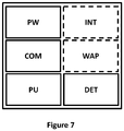
- the control device 5 is powered by a power supply unit PW and comprises memories associated with a microprocessor PU which executes and processes the instructions given to the control device 5.
- the memories can be of the ROM type (standing for “Read Only Memory” ) or RAM (standing for “Random Access Memory” ) or else Flash.
- the processor PU is controlled by a computer program, stored in a read only memory (for example a ROM memory or a hard disk). On initialization, the code instructions of the computer program are for example loaded into the random access memory before being executed by the processor PU.
- the processor PU controls the detection of change of position of the switch by the detection module DET, as well as the management of the reception and transmission of commands by the communication module COM.
- the communication module COM is able to receive from the part of remote control equipment 3 a command intended for one or more connected object (s), and / or transmit this command and / or relative information a change of position of a switch 1 to / to the connected object (s) concerned. This transmission can be done by direct communication 3.1 with the connected object (s) 2 and / or through a residential gateway 6. So that the COM communication module can transmit information relating to a change of position detected, the control device 5 also comprises a module DET for detecting a change in position of the switch 1. In other words, the detection module DET is able to detect whether the switch 1 passes from an open position, to a closed position.
- control device 5 acts as an intermediary, that is to say when the communication module COM receives and transmits to one or more connected object (s) the command sent to it (s). ) by remote control equipment 3 as illustrated in the figures 5A, 5B , 5C and 6 , the control device also comprises means of interruption INT of the electrical supply circuit 8.
- the control device 5 can also include, in the case of the embodiment of the figure 6 a module for accessing a local WAP (Wi-Fi® hotspot) communication network allowing the connected object (s) 2 to have access to this communication network.
- a module for accessing a local WAP (Wi-Fi® hotspot) communication network allowing the connected object (s) 2 to have access to this communication network.
- the figure 7 illustrates only one particular way, among several possible, of realizing the control device 5, so that it carries out the steps of the control method according to the invention (in any of the different embodiments, or in a combination of these embodiments). In fact, these steps can be carried out either on a reprogrammable computing machine (a PC computer, a DSP processor or a microcontroller) executing a program comprising a sequence of instructions, or on a dedicated computing machine (for example a set of logic gates such as an FPGA or ASIC, or any other hardware module).
- a reprogrammable computing machine a PC computer, a DSP processor or a microcontroller
- a program comprising a sequence of instructions
- a dedicated computing machine for example a set of logic gates such as an FPGA or ASIC, or any other hardware module.
Landscapes
- Engineering & Computer Science (AREA)
- Computer Networks & Wireless Communication (AREA)
- Automation & Control Theory (AREA)
- Physics & Mathematics (AREA)
- General Physics & Mathematics (AREA)
- Signal Processing (AREA)
- Telephonic Communication Services (AREA)
- Selective Calling Equipment (AREA)
Claims (9)
- System zur Steuerung mindestens eines verbundenen Objekts (2) mittels eines Unterbrechers (1), der von einer offenen Stellung in eine geschlossene Stellung und umgekehrt kippen kann, dadurch gekennzeichnet, dass es eine Kontrollvorrichtung (5) enthält, die mit dem Unterbrecher (1) in einer elektrischen Versorgungsschaltung (8) des mindestens einen verbundenen Objekts (2) parallelgeschaltet werden kann, und dass die Kontrollvorrichtung (5) enthält:- ein Erfassungsmodul (DET) einer Stellungsänderung des Unterbrechers (1); und- ein Kommunikationsmodul (COM), das eine Information (3.1) bezüglich der erfassten Stellungsänderung an das mindestens eine verbundene Objekt übertragen kann.
- Steuersystem nach Anspruch 1, dadurch gekennzeichnet, dass das Kommunikationsmodul (COM) eine für das mindestens eine verbundene Objekt (2) bestimmte Steuerung (3.1) von einem Fernsteuerungsgerät (3) empfangen und die Steuerung (3.1) an das mindestens eine verbundene Objekt (2) nach möglicher Übersetzung der Steuerung in eine an das mindestens eine verbundene Objekt (2) angepasste Kommunikationssprache übertragen kann.
- Steuersystem nach einem der Ansprüche 1 und 2, dadurch gekennzeichnet, dass das Kommunikationsmodul (COM) ebenfalls die Information bezüglich der erfassten Stellungsänderung an mindestens ein anderes verbundenes Objekt (2) übertragen kann.
- Steuersystem nach einem der Ansprüche 1 bis 3, dadurch gekennzeichnet, dass das Kommunikationsmodul (COM) ebenfalls die Information bezüglich der erfassten Stellungsänderung an eine Überwachungsvorrichtung einer menschlichen Aktivität übertragen kann.
- Steuersystem nach einem der Ansprüche 1 bis 4, dadurch gekennzeichnet, dass das Kommunikationsmodul (COM) die Information bezüglich der erfassten Stellungsänderung an das mindestens eine verbundene Objekt (2) über ein Zugangs-Gateway zu einem lokalen Kommunikationsnetz (6) übertragen kann, mit dem das mindestens eine verbundene Objekt (2) verbunden ist.
- Steuersystem nach einem der Ansprüche 1 bis 5, dadurch gekennzeichnet, dass die Kontrollvorrichtung (5) ebenfalls Unterbrechungseinrichtungen (INT) der elektrischen Versorgungsschaltung (8) des mindestens einen verbundenen Objekts (2) enthält, die betätigt werden, wenn das Erfassungsmodul (DET) eine Stellungsänderung des Unterbrechers (1) in eine offene Stellung erfasst.
- Steuersystem nach einem der Ansprüche 1 bis 6, dadurch gekennzeichnet, dass die Kontrollvorrichtung (5) ebenfalls Unterbrechungseinrichtungen (INT) der elektrischen Versorgungsschaltung (8) des mindestens einen verbundenen Objekts (2) enthält, die betätigt werden, wenn das Kommunikationsmodul (COM) vom Fernsteuerungsgerät (3) einen Abschaltbefehl des mindestens einen verbundenen Objekts (2) empfängt.
- Verfahren zur Steuerung mindestens eines verbundenen Objekts (2), das mit einer elektrischen Versorgungsschaltung verbunden ist, auf der ein Unterbrecher (1) angeordnet ist, der von einer offenen Stellung in eine geschlossene Stellung und umgekehrt kippen kann,
dadurch gekennzeichnet, dass es enthält:- einen Schritt des permanenten Unterspannungsetzens des mindestens einen verbundenen Objekts;- einen Schritt der Erfassung einer Stellungsänderung des Unterbrechers (1); und- einen Schritt der Übertragung einer Information bezüglich der erfassten Stellungsänderung an das mindestens eine verbundene Objekt. - Computerprogrammprodukt, das Programmcodeanweisungen zur Durchführung der Schritte des Steuerverfahrens nach Anspruch 8 enthält, wenn es von einem Prozessor ausgeführt wird.
Applications Claiming Priority (1)
| Application Number | Priority Date | Filing Date | Title |
|---|---|---|---|
| FR1855924A FR3081609A1 (fr) | 2018-06-29 | 2018-06-29 | Systeme de commande d'objets connectes, procede de commande et programme d'ordinateur correspondants |
Publications (2)
| Publication Number | Publication Date |
|---|---|
| EP3588461A1 EP3588461A1 (de) | 2020-01-01 |
| EP3588461B1 true EP3588461B1 (de) | 2020-12-30 |
Family
ID=63684077
Family Applications (1)
| Application Number | Title | Priority Date | Filing Date |
|---|---|---|---|
| EP19176817.5A Active EP3588461B1 (de) | 2018-06-29 | 2019-05-27 | Steuersystem von verbundenen objekten, entsprechendes steuerverfahren und computerprogramm |
Country Status (3)
| Country | Link |
|---|---|
| US (1) | US10999091B2 (de) |
| EP (1) | EP3588461B1 (de) |
| FR (1) | FR3081609A1 (de) |
Families Citing this family (1)
| Publication number | Priority date | Publication date | Assignee | Title |
|---|---|---|---|---|
| US11812533B2 (en) | 2021-06-08 | 2023-11-07 | Gmi Holdings, Inc. | Synchronized lighting with toggle system |
Family Cites Families (10)
| Publication number | Priority date | Publication date | Assignee | Title |
|---|---|---|---|---|
| CN1295917C (zh) * | 2002-08-23 | 2007-01-17 | 国际商业机器公司 | 可以感知用户周围环境的消息传递系统和方法 |
| US7839017B2 (en) * | 2009-03-02 | 2010-11-23 | Adura Technologies, Inc. | Systems and methods for remotely controlling an electrical load |
| DE112012002418B4 (de) * | 2011-06-10 | 2018-03-01 | Osram Gmbh | Elektronische Schalteranordnung |
| WO2014087518A1 (ja) | 2012-12-06 | 2014-06-12 | 株式会社 日立製作所 | ネットワークシステム及びその運用方法 |
| WO2015001041A1 (en) * | 2013-07-05 | 2015-01-08 | Lyse Smart As | A gateway system for facilitating the interoperability between different service domains and a multitude of communication protocols within and outside a home network |
| CN104023429A (zh) * | 2013-08-31 | 2014-09-03 | 张瑞锋 | 一种手机控制灯光的装置及控制方法 |
| CN204131228U (zh) * | 2014-09-30 | 2015-01-28 | 楚博纯 | 一种远程控制电路及智能家居开关 |
| EP3062586A1 (de) * | 2015-02-26 | 2016-08-31 | EchoStar UK Holdings Limited | Lichtschalter |
| CN107734213A (zh) * | 2016-08-11 | 2018-02-23 | 漳州立达信光电子科技有限公司 | 智能家用电子装置与系统 |
| US10395865B2 (en) * | 2016-12-30 | 2019-08-27 | Ecolink Intelligent Technology, Inc. | Remote-controlled switch cover assembly |
-
2018
- 2018-06-29 FR FR1855924A patent/FR3081609A1/fr active Pending
-
2019
- 2019-05-27 EP EP19176817.5A patent/EP3588461B1/de active Active
- 2019-06-28 US US16/456,560 patent/US10999091B2/en active Active
Non-Patent Citations (1)
| Title |
|---|
| None * |
Also Published As
| Publication number | Publication date |
|---|---|
| US10999091B2 (en) | 2021-05-04 |
| EP3588461A1 (de) | 2020-01-01 |
| US20200007355A1 (en) | 2020-01-02 |
| FR3081609A1 (fr) | 2019-11-29 |
Similar Documents
| Publication | Publication Date | Title |
|---|---|---|
| EP2631723B1 (de) | Verfahren zur Steuerung und Parametrierung einer Gebäudetechnik-Installation, und Gebäudetechnik-Installation zur Umsetzung dieser Verfahren | |
| US9668320B2 (en) | Path light feedback compensation | |
| FR3054340A1 (fr) | Procede de configuration, de controle ou de supervision d’une installation domotique | |
| EP3318035B1 (de) | Verfahren zur steuerung einer heimautomationsanlage | |
| WO2018015670A1 (fr) | Procédé de configuration et de supervision d'une installation domotique | |
| EP3588461B1 (de) | Steuersystem von verbundenen objekten, entsprechendes steuerverfahren und computerprogramm | |
| EP3318018B1 (de) | Verfahren zum registrieren einer zentralen steuereinheit einer heimautomatisierungsanlage und entsprechende computerprogrammprodukte | |
| EP2950249A1 (de) | Verfahren zur interaktion einer gruppe von nutzern mit einem automatismus | |
| EP1488398A2 (de) | Verfahren zur steuerung und regulierung des betriebs eines betätigungsgliedes | |
| EP3262470B1 (de) | Verfahren zur konfiguration und verfahren zum befehlen und/oder steuern einer heimautomatisierungsgerätschnittstelle | |
| EP3216096A1 (de) | Elektrische verbindungsstelle in einer wand in einem wohngebäude und elektrische anlage mit mindestens einer solchen verbindungsstelle | |
| FR3050842A1 (fr) | Systeme de menuiserie communicante et procede de fabrication correspondant. | |
| EP3811573B1 (de) | Verfahren zur konfiguration einer zentralen steuereinheit eines heimautomatisierungssystems | |
| EP4000053B1 (de) | Verfahren zur konfigurierung der kommunikation zwischen mindestens einem aktuator und einer fernbedienung | |
| BE1023878B1 (fr) | Installation électrique domestique | |
| EP1771974A1 (de) | Verfahren und system zur steuerung technischer elemente zum betrieb zu hause und/oder bei der arbeit | |
| WO2021009423A1 (fr) | Procédé et dispositif de commande sans fil pour actionneurs couplés à un réseau filaire | |
| EP3140962B1 (de) | System zur verwaltung einer struktur mit einer box mit redundanten verbindungen | |
| FR3073314A1 (fr) | Appareil de commande radio permettant de commander un equipement electrique, installation correspondante et systeme correspondant | |
| BE1023659B1 (nl) | Besturingssysteem voor een thuisnetwerk en centraal besturingsapparaat daarin toegepast. | |
| FR3077946A1 (fr) | Procede d’appairage, plateforme domotique multinoeuds, equipement domotique multinoeuds et systeme domotique associes | |
| FR3126479A3 (fr) | Ensemble de contrôle de climatisation zonée par le biais de conduits d'air ou d'eau avec des thermostats radio | |
| WO2017178646A1 (fr) | Dispositif électrique communiquant par ultrasons et procédé de contrôle d'un système comprenant un tel dispositif électrique | |
| WO2012001267A1 (fr) | Gestion de panne applicative dans un systeme d'equipements domestiques |
Legal Events
| Date | Code | Title | Description |
|---|---|---|---|
| PUAI | Public reference made under article 153(3) epc to a published international application that has entered the european phase |
Free format text: ORIGINAL CODE: 0009012 |
|
| STAA | Information on the status of an ep patent application or granted ep patent |
Free format text: STATUS: THE APPLICATION HAS BEEN PUBLISHED |
|
| AK | Designated contracting states |
Kind code of ref document: A1 Designated state(s): AL AT BE BG CH CY CZ DE DK EE ES FI FR GB GR HR HU IE IS IT LI LT LU LV MC MK MT NL NO PL PT RO RS SE SI SK SM TR |
|
| AX | Request for extension of the european patent |
Extension state: BA ME |
|
| STAA | Information on the status of an ep patent application or granted ep patent |
Free format text: STATUS: REQUEST FOR EXAMINATION WAS MADE |
|
| RAP1 | Party data changed (applicant data changed or rights of an application transferred) |
Owner name: ORANGE |
|
| 17P | Request for examination filed |
Effective date: 20200622 |
|
| RBV | Designated contracting states (corrected) |
Designated state(s): AL AT BE BG CH CY CZ DE DK EE ES FI FR GB GR HR HU IE IS IT LI LT LU LV MC MK MT NL NO PL PT RO RS SE SI SK SM TR |
|
| RIC1 | Information provided on ipc code assigned before grant |
Ipc: H05B 47/19 20200101ALI20200804BHEP Ipc: G08C 17/02 20060101AFI20200804BHEP Ipc: H01H 89/00 20060101ALI20200804BHEP |
|
| GRAP | Despatch of communication of intention to grant a patent |
Free format text: ORIGINAL CODE: EPIDOSNIGR1 |
|
| STAA | Information on the status of an ep patent application or granted ep patent |
Free format text: STATUS: GRANT OF PATENT IS INTENDED |
|
| INTG | Intention to grant announced |
Effective date: 20200924 |
|
| GRAS | Grant fee paid |
Free format text: ORIGINAL CODE: EPIDOSNIGR3 |
|
| GRAA | (expected) grant |
Free format text: ORIGINAL CODE: 0009210 |
|
| STAA | Information on the status of an ep patent application or granted ep patent |
Free format text: STATUS: THE PATENT HAS BEEN GRANTED |
|
| AK | Designated contracting states |
Kind code of ref document: B1 Designated state(s): AL AT BE BG CH CY CZ DE DK EE ES FI FR GB GR HR HU IE IS IT LI LT LU LV MC MK MT NL NO PL PT RO RS SE SI SK SM TR |
|
| REG | Reference to a national code |
Ref country code: GB Ref legal event code: FG4D Free format text: NOT ENGLISH |
|
| REG | Reference to a national code |
Ref country code: AT Ref legal event code: REF Ref document number: 1350701 Country of ref document: AT Kind code of ref document: T Effective date: 20210115 |
|
| REG | Reference to a national code |
Ref country code: DE Ref legal event code: R096 Ref document number: 602019001951 Country of ref document: DE |
|
| REG | Reference to a national code |
Ref country code: IE Ref legal event code: FG4D Free format text: LANGUAGE OF EP DOCUMENT: FRENCH |
|
| PG25 | Lapsed in a contracting state [announced via postgrant information from national office to epo] |
Ref country code: FI Free format text: LAPSE BECAUSE OF FAILURE TO SUBMIT A TRANSLATION OF THE DESCRIPTION OR TO PAY THE FEE WITHIN THE PRESCRIBED TIME-LIMIT Effective date: 20201230 Ref country code: RS Free format text: LAPSE BECAUSE OF FAILURE TO SUBMIT A TRANSLATION OF THE DESCRIPTION OR TO PAY THE FEE WITHIN THE PRESCRIBED TIME-LIMIT Effective date: 20201230 Ref country code: GR Free format text: LAPSE BECAUSE OF FAILURE TO SUBMIT A TRANSLATION OF THE DESCRIPTION OR TO PAY THE FEE WITHIN THE PRESCRIBED TIME-LIMIT Effective date: 20210331 Ref country code: NO Free format text: LAPSE BECAUSE OF FAILURE TO SUBMIT A TRANSLATION OF THE DESCRIPTION OR TO PAY THE FEE WITHIN THE PRESCRIBED TIME-LIMIT Effective date: 20210330 |
|
| REG | Reference to a national code |
Ref country code: AT Ref legal event code: MK05 Ref document number: 1350701 Country of ref document: AT Kind code of ref document: T Effective date: 20201230 |
|
| PG25 | Lapsed in a contracting state [announced via postgrant information from national office to epo] |
Ref country code: BG Free format text: LAPSE BECAUSE OF FAILURE TO SUBMIT A TRANSLATION OF THE DESCRIPTION OR TO PAY THE FEE WITHIN THE PRESCRIBED TIME-LIMIT Effective date: 20210330 Ref country code: SE Free format text: LAPSE BECAUSE OF FAILURE TO SUBMIT A TRANSLATION OF THE DESCRIPTION OR TO PAY THE FEE WITHIN THE PRESCRIBED TIME-LIMIT Effective date: 20201230 Ref country code: LV Free format text: LAPSE BECAUSE OF FAILURE TO SUBMIT A TRANSLATION OF THE DESCRIPTION OR TO PAY THE FEE WITHIN THE PRESCRIBED TIME-LIMIT Effective date: 20201230 |
|
| REG | Reference to a national code |
Ref country code: NL Ref legal event code: MP Effective date: 20201230 |
|
| PG25 | Lapsed in a contracting state [announced via postgrant information from national office to epo] |
Ref country code: HR Free format text: LAPSE BECAUSE OF FAILURE TO SUBMIT A TRANSLATION OF THE DESCRIPTION OR TO PAY THE FEE WITHIN THE PRESCRIBED TIME-LIMIT Effective date: 20201230 |
|
| REG | Reference to a national code |
Ref country code: LT Ref legal event code: MG9D |
|
| RAP4 | Party data changed (patent owner data changed or rights of a patent transferred) |
Owner name: ORANGE |
|
| PG25 | Lapsed in a contracting state [announced via postgrant information from national office to epo] |
Ref country code: LT Free format text: LAPSE BECAUSE OF FAILURE TO SUBMIT A TRANSLATION OF THE DESCRIPTION OR TO PAY THE FEE WITHIN THE PRESCRIBED TIME-LIMIT Effective date: 20201230 Ref country code: RO Free format text: LAPSE BECAUSE OF FAILURE TO SUBMIT A TRANSLATION OF THE DESCRIPTION OR TO PAY THE FEE WITHIN THE PRESCRIBED TIME-LIMIT Effective date: 20201230 Ref country code: PT Free format text: LAPSE BECAUSE OF FAILURE TO SUBMIT A TRANSLATION OF THE DESCRIPTION OR TO PAY THE FEE WITHIN THE PRESCRIBED TIME-LIMIT Effective date: 20210430 Ref country code: CZ Free format text: LAPSE BECAUSE OF FAILURE TO SUBMIT A TRANSLATION OF THE DESCRIPTION OR TO PAY THE FEE WITHIN THE PRESCRIBED TIME-LIMIT Effective date: 20201230 Ref country code: EE Free format text: LAPSE BECAUSE OF FAILURE TO SUBMIT A TRANSLATION OF THE DESCRIPTION OR TO PAY THE FEE WITHIN THE PRESCRIBED TIME-LIMIT Effective date: 20201230 Ref country code: SK Free format text: LAPSE BECAUSE OF FAILURE TO SUBMIT A TRANSLATION OF THE DESCRIPTION OR TO PAY THE FEE WITHIN THE PRESCRIBED TIME-LIMIT Effective date: 20201230 |
|
| PG25 | Lapsed in a contracting state [announced via postgrant information from national office to epo] |
Ref country code: PL Free format text: LAPSE BECAUSE OF FAILURE TO SUBMIT A TRANSLATION OF THE DESCRIPTION OR TO PAY THE FEE WITHIN THE PRESCRIBED TIME-LIMIT Effective date: 20201230 Ref country code: AT Free format text: LAPSE BECAUSE OF FAILURE TO SUBMIT A TRANSLATION OF THE DESCRIPTION OR TO PAY THE FEE WITHIN THE PRESCRIBED TIME-LIMIT Effective date: 20201230 |
|
| PG25 | Lapsed in a contracting state [announced via postgrant information from national office to epo] |
Ref country code: IS Free format text: LAPSE BECAUSE OF FAILURE TO SUBMIT A TRANSLATION OF THE DESCRIPTION OR TO PAY THE FEE WITHIN THE PRESCRIBED TIME-LIMIT Effective date: 20210430 |
|
| REG | Reference to a national code |
Ref country code: DE Ref legal event code: R097 Ref document number: 602019001951 Country of ref document: DE |
|
| PG25 | Lapsed in a contracting state [announced via postgrant information from national office to epo] |
Ref country code: AL Free format text: LAPSE BECAUSE OF FAILURE TO SUBMIT A TRANSLATION OF THE DESCRIPTION OR TO PAY THE FEE WITHIN THE PRESCRIBED TIME-LIMIT Effective date: 20201230 Ref country code: IT Free format text: LAPSE BECAUSE OF FAILURE TO SUBMIT A TRANSLATION OF THE DESCRIPTION OR TO PAY THE FEE WITHIN THE PRESCRIBED TIME-LIMIT Effective date: 20201230 |
|
| PLBE | No opposition filed within time limit |
Free format text: ORIGINAL CODE: 0009261 |
|
| STAA | Information on the status of an ep patent application or granted ep patent |
Free format text: STATUS: NO OPPOSITION FILED WITHIN TIME LIMIT |
|
| PG25 | Lapsed in a contracting state [announced via postgrant information from national office to epo] |
Ref country code: DK Free format text: LAPSE BECAUSE OF FAILURE TO SUBMIT A TRANSLATION OF THE DESCRIPTION OR TO PAY THE FEE WITHIN THE PRESCRIBED TIME-LIMIT Effective date: 20201230 |
|
| 26N | No opposition filed |
Effective date: 20211001 |
|
| PG25 | Lapsed in a contracting state [announced via postgrant information from national office to epo] |
Ref country code: ES Free format text: LAPSE BECAUSE OF FAILURE TO SUBMIT A TRANSLATION OF THE DESCRIPTION OR TO PAY THE FEE WITHIN THE PRESCRIBED TIME-LIMIT Effective date: 20201230 Ref country code: LU Free format text: LAPSE BECAUSE OF NON-PAYMENT OF DUE FEES Effective date: 20210527 Ref country code: MC Free format text: LAPSE BECAUSE OF FAILURE TO SUBMIT A TRANSLATION OF THE DESCRIPTION OR TO PAY THE FEE WITHIN THE PRESCRIBED TIME-LIMIT Effective date: 20201230 |
|
| REG | Reference to a national code |
Ref country code: BE Ref legal event code: MM Effective date: 20210531 |
|
| PG25 | Lapsed in a contracting state [announced via postgrant information from national office to epo] |
Ref country code: SI Free format text: LAPSE BECAUSE OF FAILURE TO SUBMIT A TRANSLATION OF THE DESCRIPTION OR TO PAY THE FEE WITHIN THE PRESCRIBED TIME-LIMIT Effective date: 20201230 |
|
| PG25 | Lapsed in a contracting state [announced via postgrant information from national office to epo] |
Ref country code: IE Free format text: LAPSE BECAUSE OF NON-PAYMENT OF DUE FEES Effective date: 20210527 |
|
| PG25 | Lapsed in a contracting state [announced via postgrant information from national office to epo] |
Ref country code: IS Free format text: LAPSE BECAUSE OF FAILURE TO SUBMIT A TRANSLATION OF THE DESCRIPTION OR TO PAY THE FEE WITHIN THE PRESCRIBED TIME-LIMIT Effective date: 20210430 |
|
| PG25 | Lapsed in a contracting state [announced via postgrant information from national office to epo] |
Ref country code: BE Free format text: LAPSE BECAUSE OF NON-PAYMENT OF DUE FEES Effective date: 20210531 |
|
| REG | Reference to a national code |
Ref country code: CH Ref legal event code: PL |
|
| PG25 | Lapsed in a contracting state [announced via postgrant information from national office to epo] |
Ref country code: LI Free format text: LAPSE BECAUSE OF NON-PAYMENT OF DUE FEES Effective date: 20220531 Ref country code: CH Free format text: LAPSE BECAUSE OF NON-PAYMENT OF DUE FEES Effective date: 20220531 |
|
| PG25 | Lapsed in a contracting state [announced via postgrant information from national office to epo] |
Ref country code: NL Free format text: LAPSE BECAUSE OF NON-PAYMENT OF DUE FEES Effective date: 20201230 Ref country code: CY Free format text: LAPSE BECAUSE OF FAILURE TO SUBMIT A TRANSLATION OF THE DESCRIPTION OR TO PAY THE FEE WITHIN THE PRESCRIBED TIME-LIMIT Effective date: 20201230 |
|
| PG25 | Lapsed in a contracting state [announced via postgrant information from national office to epo] |
Ref country code: SM Free format text: LAPSE BECAUSE OF FAILURE TO SUBMIT A TRANSLATION OF THE DESCRIPTION OR TO PAY THE FEE WITHIN THE PRESCRIBED TIME-LIMIT Effective date: 20201230 Ref country code: HU Free format text: LAPSE BECAUSE OF FAILURE TO SUBMIT A TRANSLATION OF THE DESCRIPTION OR TO PAY THE FEE WITHIN THE PRESCRIBED TIME-LIMIT; INVALID AB INITIO Effective date: 20190527 |
|
| PGFP | Annual fee paid to national office [announced via postgrant information from national office to epo] |
Ref country code: FR Payment date: 20230420 Year of fee payment: 5 Ref country code: DE Payment date: 20230419 Year of fee payment: 5 |
|
| PGFP | Annual fee paid to national office [announced via postgrant information from national office to epo] |
Ref country code: GB Payment date: 20230420 Year of fee payment: 5 |
|
| PG25 | Lapsed in a contracting state [announced via postgrant information from national office to epo] |
Ref country code: MK Free format text: LAPSE BECAUSE OF FAILURE TO SUBMIT A TRANSLATION OF THE DESCRIPTION OR TO PAY THE FEE WITHIN THE PRESCRIBED TIME-LIMIT Effective date: 20201230 |