EP2345831A1 - Absperrelement - Google Patents
Absperrelement Download PDFInfo
- Publication number
- EP2345831A1 EP2345831A1 EP10016220A EP10016220A EP2345831A1 EP 2345831 A1 EP2345831 A1 EP 2345831A1 EP 10016220 A EP10016220 A EP 10016220A EP 10016220 A EP10016220 A EP 10016220A EP 2345831 A1 EP2345831 A1 EP 2345831A1
- Authority
- EP
- European Patent Office
- Prior art keywords
- shut
- threaded insert
- element according
- base body
- saddle
- Prior art date
- Legal status (The legal status is an assumption and is not a legal conclusion. Google has not performed a legal analysis and makes no representation as to the accuracy of the status listed.)
- Granted
Links
- 230000000903 blocking effect Effects 0.000 title 1
- 238000007789 sealing Methods 0.000 claims abstract description 29
- 239000002184 metal Substances 0.000 claims abstract description 5
- 229910052751 metal Inorganic materials 0.000 claims abstract description 5
- 239000007769 metal material Substances 0.000 claims abstract description 5
- 229910010293 ceramic material Inorganic materials 0.000 claims abstract description 3
- 229920001971 elastomer Polymers 0.000 claims abstract description 3
- 239000000806 elastomer Substances 0.000 claims abstract description 3
- 230000000087 stabilizing effect Effects 0.000 claims description 18
- 239000000463 material Substances 0.000 claims description 5
- 239000011324 bead Substances 0.000 claims description 4
- 230000002093 peripheral effect Effects 0.000 claims description 3
- 230000008878 coupling Effects 0.000 description 5
- 238000010168 coupling process Methods 0.000 description 5
- 238000005859 coupling reaction Methods 0.000 description 5
- 239000000919 ceramic Substances 0.000 description 4
- 238000004519 manufacturing process Methods 0.000 description 3
- 238000001746 injection moulding Methods 0.000 description 2
- 238000007639 printing Methods 0.000 description 2
- 229910001141 Ductile iron Inorganic materials 0.000 description 1
- 230000005540 biological transmission Effects 0.000 description 1
- 230000015572 biosynthetic process Effects 0.000 description 1
- 150000001875 compounds Chemical class 0.000 description 1
- 230000001419 dependent effect Effects 0.000 description 1
- 230000000694 effects Effects 0.000 description 1
- 238000002347 injection Methods 0.000 description 1
- 239000007924 injection Substances 0.000 description 1
- 238000009434 installation Methods 0.000 description 1
- 238000005507 spraying Methods 0.000 description 1
- 230000006641 stabilisation Effects 0.000 description 1
- 238000011105 stabilization Methods 0.000 description 1
Images



Classifications
-
- F—MECHANICAL ENGINEERING; LIGHTING; HEATING; WEAPONS; BLASTING
- F16—ENGINEERING ELEMENTS AND UNITS; GENERAL MEASURES FOR PRODUCING AND MAINTAINING EFFECTIVE FUNCTIONING OF MACHINES OR INSTALLATIONS; THERMAL INSULATION IN GENERAL
- F16K—VALVES; TAPS; COCKS; ACTUATING-FLOATS; DEVICES FOR VENTING OR AERATING
- F16K3/00—Gate valves or sliding valves, i.e. cut-off apparatus with closing members having a sliding movement along the seat for opening and closing
- F16K3/30—Details
- F16K3/314—Forms or constructions of slides; Attachment of the slide to the spindle
-
- F—MECHANICAL ENGINEERING; LIGHTING; HEATING; WEAPONS; BLASTING
- F16—ENGINEERING ELEMENTS AND UNITS; GENERAL MEASURES FOR PRODUCING AND MAINTAINING EFFECTIVE FUNCTIONING OF MACHINES OR INSTALLATIONS; THERMAL INSULATION IN GENERAL
- F16K—VALVES; TAPS; COCKS; ACTUATING-FLOATS; DEVICES FOR VENTING OR AERATING
- F16K31/00—Actuating devices; Operating means; Releasing devices
- F16K31/44—Mechanical actuating means
- F16K31/50—Mechanical actuating means with screw-spindle or internally threaded actuating means
- F16K31/508—Mechanical actuating means with screw-spindle or internally threaded actuating means the actuating element being rotatable, non-rising, and driving a non-rotatable axially-sliding element
Definitions
- the invention relates to a shut-off element having a base body and an opening for receiving a threaded spindle engaged with a threaded insert.
- shut-off valves for pipelines usually have shut-off elements arranged transversely to the direction of flow in the valve housing, which have an opening in their interior for receiving a valve spindle, and are connected thereto by way of a threaded engagement.
- the shut-off element moves in the spindle longitudinal direction from an open position to a closed position.
- such shut-off elements have elastic sealing portions which press in the closed position against the inner surfaces of the pipe and thus achieve a shut-off of the pipeline, and sliding body or Gleitauf accounts for guiding the shutoff in a correspondingly designed slide chamber.
- shut-off elements are for example in the publications EP 0 171 693 A2 and US 4,629,160 described.
- the main body of these shut-off elements, to which the sealing portions are applied, and which has the opening for receiving the spool, is generally made of a metallic material, such as MS or ductile iron, and in exceptional cases of plastic by an injection molding process.
- the above-mentioned sliding bodies or sliding attachments are generally made of plastic.
- valve stem which is generally by a threaded insert made of a hard material, preferably metal or ceramic, having an internal thread, which is in engagement with the external thread of the valve stem.
- the document EP 1 516 138 B1 shows various ways in which the threaded insert can be connected to the shut-off element.
- the threaded insert can be connected via a releasable coupling arrangement with the shut-off element, and at least partially comprise the shut-off element for reasons of stability.
- shut-off element In terms of increased robustness and longer durability of the shut-off element, it would be advantageous to carry out the threaded insert in one piece with the shut-off element. For this purpose, however, it would be necessary to produce the entire shut-off element, or at least its base body, from the same material as the threaded insert, that is to say preferably metal or ceramic. This is not desirable for cost reasons. If the shut-off element is molded from softer materials such as plastic, the thread for the spool would not have the required strength.
- the threaded insert is positively connected to the main body of the shut-off element and cast in particular in this. As a result, a cost-effective production of the device is achieved. Additional coupling elements, such as flanges or screws omitted.
- the Threaded insert can be made of a metallic material or of ceramic, to allow a good engagement in the external thread of the valve stem.
- the base can be cast inexpensively from a temperature-resistant plastic.
- the main body can be designed in several parts, wherein the threaded insert is inserted in the assembly of the main body in this.
- the main body has a, the position of the threaded insert stabilizing saddle.
- This saddle can be a part of the basic body, or be connected to this.
- the threaded insert has stabilizing elements that fix its position in the saddle.
- the saddle is designed in the form of a shell which partially surrounds the circumference of the basic body. This achieves a good transmission of the forces acting on the saddle.
- the width of the saddle is greater than or equal to the width of the base body.
- the threaded insert has various stabilizing elements in order to forward the forces acting on the threaded insert to the saddle or to the main body of the shut-off element. It is inventively provided that the threaded insert has at least one stabilizing pressure plate. This is to pass on the contact pressure of the slide spindle via the threaded insert on the body. Furthermore, the threaded insert over at least one, the threaded insert against Have torsion securing transversal rib. Such transverse ribs can in particular be mounted on the printing plates, for example on their upper side and / or their lower side. These are intended to prevent the threaded insert from being torn out of the basic body by twisting or twisting.
- threaded insert circumferential ribs that allow a firm connection of the threaded insert with the body and in particular protect the threaded insert against pulling out of the body or pushing into the body.
- the threaded insert has an opening in which there is an internal thread which engages with an external thread of the valve spindle.
- a threaded collar For positioning during spraying may be provided on the outer circumference of the threaded insert a threaded collar.
- a threaded collar also serves as a further stabilizing means against pushing in or pulling out of the threaded insert in or out of the main body.
- the present invention particularly comprises an embodiment in which sealing elements are fastened to opposing support surfaces of the base body, which may have at least one peripheral edge bead.
- support discs may be provided, which are fixed together by fastening means and thereby fasten the sealing elements on the base body.
- These support disks can be designed in particular in the form of support plates.
- the sealing elements can also be attached directly to the base body, for example glued, clamped or vulcanized.
- the base body, the sealing elements and / or the support disks have corresponding recesses for receiving these fastening means.
- the main body via guide extensions in the form of tabs, springs or the like non-rotating mounting of the shutoff feature.
- These guide extensions can be provided on the outer circumference of the base body and / or in the region of the saddle or in the region of the threaded insert.
- These guide projections can be supplemented by corresponding recesses in the slide chamber of a gate valve, whereby the position of the shut-off element is defined during the opening and closing of the flow channel.
- the threaded insert consists of metal or a ceramic material
- the base body is made of plastic.
- the mentioned sealing elements may consist of elastomers, plastic, or of high-temperature resistant and / or resistant to aggressive media materials.
- Fig. 1 shows a cross section through a shut-off valve 2 with a shut-off element 1 according to the invention in the closed position.
- the shut-off valve 2 comprises a flow channel 27, a slide chamber 28 and a housing extension 29.
- the slide spindle 7 is mounted in the housing extension 29 by means of the spindle bearing 32 and rotatably connected to the shut-off element 1 according to the invention.
- the slide spindle has an external thread 10 and the shut-off element 1 via a threaded insert 8, which has an internal thread 9.
- the shut-off element 1 moves along the longitudinal axis 30, wherein the shut-off element 1 accommodates the slide spindle 7 in an opening 6.
- the shut-off element 1 comprises a main body 5, on whose support surfaces sealing elements 4 are arranged, which are fastened by the support plates 14 on the main body 5. Furthermore, the shut-off valve 2 includes the end flanges 31 for attachment of the incoming and outgoing pipes, although other embodiments of the invention may of course also have other connection forms.
- the shut-off element 1 according to the invention is not limited to use in the shut-off valve shown, but can also be used in differently constructed shut-off valves, which are actuated via a slide spindle.
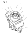
- FIG. 2 shows a three-dimensional view of the main body 5 and the threaded insert 8 of the shutoff 1.
- the main body 5 has an opening 6 for receiving the spool 7.
- the threaded insert 8 which has an internal thread 9.
- the base body 5 is practically inseparably connected to the threaded insert 8.
- this is achieved by introducing the threaded insert 8, which consists of a metallic material or ceramic, into the injection mold of the plastic body 5.
- the threaded insert 8 could be separated only by destroying the body 5 of this.
- the main body 5 further has the guide extensions 16, the. Stabilization of the shut-off engage in guide grooves of the slide chamber 28.
- the threaded insert 8 is subjected to a strong stress upon actuation of the slide spindle, since a considerable contact pressure must be expended in order to reliably seal the flow channel 27.
- the base body 5 in the region of the threaded insert 8 a the position of the threaded insert 8 stabilizing saddle 17 has.
- This saddle 17 may be formed in the form of a, the periphery of the body 5 partially comprehensive, shell. Through this saddle 17, it is possible to fix the threaded insert 8 by additional, extended stabilizing elements 25 on the main body 5.
- the stabilizing elements 25 are in FIG. 3 detailed.
- FIG. 3 In order to stabilize the thread, the threaded insert 8 has a threaded collar 21 on its outer circumference. Several stabilizing elements 25 serve to fix the threaded insert 8 in the saddle 17 of the main body 5.
- the peripheral ribs 12 are in particular a withdrawal in the direction of the longitudinal axis 30 of the threaded insert 8 from the main body 5, or a pushing of the threaded insert 8 in the main body 5, avoid.
- a pressure plate 11 is provided to achieve a homogeneous distribution of, exerted by the actuation of the slide spindle 7, contact pressure on the shut-off element 1.
- the pressure plate 11 also acts a rotation of the threaded insert eighth in the saddle 17 opposite.
- protruding for this purpose on the pressure plate 11 transverse ribs 22 are provided.
- FIGS. 4 to 6 show different cross sections through the shutoff of the invention FIG. 1 ,
- the shut-off element 1 comprises the main body 5, the threaded insert 8, the sealing elements 4 and the support plates 14.
- the main body 5 forms a saddle 17 in the region of the threaded insert 8.
- This saddle 17 has the shape of a, the circumference of the body 5 partially comprehensive shell.
- the saddle 17 has a width 18 that is greater than the width 19 of the main body 5, as in FIG. 5 is shown.
- the threaded insert 8 includes for stabilizing the internal thread 9 a threaded collar 21. Furthermore, the circumferential ribs 12 and the pressure plate 11 of the threaded insert 8 can be seen.
- the main body 5 forms on its circumference the guide extensions 16, which serve to guide the shut-off element 1 in the slide chamber 28.
- the shut-off element 1 comprises the sealing elements 4, which are attached to the opposite support surfaces 3 of the main body 5. These sealing elements 4 are fastened in the present embodiment by the support plates 14 on the base body 5.
- the fastening means 26 are provided.
- the main body 5 has the stiffening ribs 13, which also allow a fixation of the sealing elements 4.
- the sealing elements 4 At its outer periphery, have the edge bead 23, which serves to improve the sealing behavior of the shut-off element.
- FIG. 6 shows a section through the shut-off element 1 along the line VI-VI in FIG. 4 ,
- the fastening means 26 are shown. These are formed in the present embodiment by the rivets 15, which are guided by corresponding recesses 20 in the main body 5, the sealing elements 4 and the support plates 14. By compressing the rivets 15, the location of Sealing elements 4 fixed to the base body 5.
- a plurality of stiffening ribs 33, which engage in corresponding recesses of the sealing elements 4, also serves to fix the sealing elements 4.
- shut-off invention is not limited to the embodiment shown.
- shut-off elements are part of the invention, in which the threaded insert 8 and the main body 5 are made in one piece.
Landscapes
- Engineering & Computer Science (AREA)
- General Engineering & Computer Science (AREA)
- Mechanical Engineering (AREA)
- Valve Housings (AREA)
- Sliding Valves (AREA)
- Multiple-Way Valves (AREA)
- Connection Of Plates (AREA)
Abstract
Description
- Die Erfindung betrifft ein Absperrelement mit einem Grundkörper und einer Öffnung zur Aufnahme einer mit einem Gewindeeinsatz in Eingriff stehenden Schieberspindel.
- Absperrarmaturen für Rohrleitungen verfügen meist über quer zur Strömungsrichtung im Schiebergehäuse angeordnete Absperrelemente, die in ihrem Inneren eine Öffnung zur Aufnahme einer Schieberspindel aufweisen, und mit dieser über einen Gewindeeingriff verbunden sind. Bei Betätigung der Schieberspindel bewegt sich das Absperrelement in Spindellängsrichtung aus einer Offenstellung in eine Schließstellung. An ihrem Umfang verfügen derartige Absperrelemente über elastische Dichtabschnitte, die in der Schließstellung gegen die Innenflächen der Rohrleitung pressen und damit eine Absperrung der Rohrleitung erzielen, und Gleitkörper bzw. Gleitaufsätze zur Führung des Absperrelements in einer entsprechend ausgeführten Schieberkammer.
- Derartige Absperrelemente sind beispielsweise in den Druckschriften
EP 0 171 693 A2 undUS 4 629 160 beschrieben. Der Grundkörper dieser Absperrelemente, auf den die Dichtabschnitte aufgebracht werden, und der die Öffnung zur Aufnahme der Schieberspindel aufweist, wird im Allgemeinen aus einem metallischen Werkstoff, beispielsweise MS oder Sphäroguss, und in Ausnahmefällen aus Kunststoff durch ein Spritzgussverfahren hergestellt. Im Gegensatz dazu werden die oben erwähnten Gleitkörper bzw. Gleitaufsätze im Allgemeinen aus Kunststoff hergestellt. - Von besonderer Bedeutung für die Stabilität und Dichtwirkung des Absperrelements ist die Verbindung mit der Schieberspindel, die im Allgemeinen durch einen Gewindeeinsatz aus einem harten Material, bevorzugt Metall oder Keramik, erfolgt, der ein Innengewinde aufweist, das mit dem Außengewinde der Schieberspindel in Eingriff steht. Das Dokument
EP 1 516 138 B1 zeigt verschiedene Möglichkeiten, wie der Gewindeeinsatz mit dem Absperrelement verbunden werden kann. Insbesondere kann der Gewindeeinsatz über eine lösbare Kupplungsanordnung mit dem Absperrelement verbunden sein, und das Absperrelement aus Stabilitätsgründen zumindest teilweise umfassen. - Eine derartige Kupplung mittels lösbarer Verbindungselemente hat sich jedoch als nachteilig im Bezug auf die Haltbarkeit der Verbindung herausgestellt. Im Sinne einer erhöhten Robustheit und längeren Haltbarkeit des Absperrelements wäre es vorteilhaft, den Gewindeeinsatz einstückig mit dem Absperrelement auszuführen. Dazu wäre es jedoch erforderlich, das gesamte Absperrelement, oder zumindest dessen Grundkörper, aus dem selben Material wie den Gewindeeinsatz, also bevorzugt Metall oder Keramik, herzustellen. Dies ist aus Kostengründen nicht erwünscht. Wenn das Absperrelement aus weicheren Materialien wie Kunststoff geformt wird, hätte das Gewinde für die Schieberspindel nicht die erforderliche Festigkeit.
- Es ist deshalb Aufgabe der Erfindung, ein Absperrelement vorzusehen, dass einerseits möglichst kostengünstig hergestellt werden kann, und andererseits eine möglichst robuste und langlebige Kopplung des Absperrelements mit dem Gewindeeinsatz ermöglicht. Gleichzeitig soll die Verbindung des Gewindeeinsatzes mit dem Absperrelement platzsparend erfolgen, um eine einfache Montage der Vorrichtung zu ermöglichen. Zusätzliche Verbindungselemente sollten tunlichst vermieden werden.
- Diese Aufgabe der Erfindung wird durch die im kennzeichnenden Teil des Anspruchs 1 genannten Merkmale erreicht. Der Gewindeeinsatz ist formschlüssig mit dem Grundkörper des Absperrelements verbunden und insbesondere in diesen eingegossen. Dadurch wird eine kostengünstige Herstellung der Vorrichtung erreicht. Zusätzliche Kupplungselemente, wie Flansche oder Schrauben, entfallen. Der Gewindeeinsatz kann aus einem metallischen Werkstoff oder aus Keramik gefertigt werden, um einen guten Eingriff in das Außengewinde der Schieberspindel zu ermöglichen. Gleichzeitig kann der Grundkörper kostengünstig aus einem temperaturbeständigen Kunststoff gegossen werden. Durch die, in den Unteransprüchen beschriebenen, Versteifungs- und Stabilisierungsmittel wird einer Verdrehung oder Lockerung des Gewindeeinsatzes zuverlässig entgegengewirkt. Die umfangsseitig angeordneten Gleitkörper bzw. Gleitaufsätze aus Kunststoff können direkt mit dem Grundkörper mitgegossen werden, wodurch die Herstellung weiter vereinfacht wird.
- Erfindungsgemäß ist ebenfalls vorgesehen, dass der Grundkörper mehrteilig ausgeführt sein kann, wobei der Gewindeeinsatz beim Zusammenbau des Grundkörpers in diesen eingelegt wird.
- Zur Stabilisierung des Gewindeeinsatzes ist erfindungsgemäß vorgesehen, dass der Grundkörper einen, die Position des Gewindeeinsatzes stabilisierenden Sattel aufweist. Dieser Sattel kann ein Teil des Grundkörpers, oder mit diesem verbunden sein. Der Gewindeeinsatz verfügt über Stabilisierungselemente, die dessen Position im Sattel fixieren. Es ist insbesondere vorgesehen, dass der Sattel in Form einer den Umfang des Grundkörpers teilweise umfassenden Schale ausgebildet ist. Dadurch wird eine gute Weiterleitung der auf den Sattel wirkenden Kräfte erreicht. Insbesondere ist vorgesehen, dass die Breite des Sattels größer oder gleich der Breite des Grundkörpers ist. Dadurch wird einerseits die Kopplung des Gewindeeinsatzes mit dem Grundkörper verbessert, und andererseits verhindert, dass die am Umfang des Grundkörpers befindlichen Dichtungen nicht nach oben verschoben werden können. Es ist aber auch möglich, den Sattel gleich groß oder schmäler als den Grundkörper auszuführen.
- Wie oben erwähnt, verfügt der Gewindeeinsatz über verschiedene Stabilisierungselemente, um die auf den Gewindeeinsatz wirkenden Kräfte an den Sattel- bzw. an den Grundkörper des Absperrelements weiterzuleiten. Es ist erfindungsgemäß vorgesehen, dass der Gewindeeinsatz über zumindest eine stabilisierende Druckplatte verfügt. Diese soll den Anpressdruck von der Schieberspindel über den Gewindeeinsatz auf den Grundkörper weiterleiten. Weiters kann der Gewindeeinsatz über mindestens eine, den Gewindeeinsatz gegen Verdrehung sichernde Transversalrippe aufweisen. Derartige Transversalrippen können insbesondere auf den Druckplatten, beispielsweise an deren Oberseite und/oder deren Unterseite, angebracht werden. Diese sollen verhindern, dass der Gewindeeinsatz durch Verdrehung bzw. Verwindung aus dem Grundkörper gerissen wird.
- Als zusätzliche Unterstützung können am Gewindeeinsatz Umfangsrippen vorgesehen sein, die eine feste Verbindung des Gewindeeinsatzes mit dem Grundkörper ermöglichen und insbesondere dem Gewindeeinsatz gegen Herausziehen aus dem Grundkörper bzw. Hineindrücken in den Grundkörper schützen.
- Es ist ein weiteres Merkmal der Erfindung, dass der Gewindeeinsatz eine Öffnung aufweist, in der sich ein Innengewinde befindet, welches mit einem Außengewinde der Schieberspindel in Eingriff steht. Zur Positionierung beim Spritzen kann am äußeren Umfang des Gewindeeinsatzes ein Gewindebund vorgesehen sein. Ein derartiger Gewindebund dient auch als weiteres Stabilisierungsmittel gegen ein Hineindrücken oder Herausziehen des Gewindeeinsatzes in bzw. aus dem Grundkörper.
- Bezüglich der Ausführung des Grundkörpers umfasst die vorliegende Erfindung insbesondere eine Ausführungsform, bei der an gegenüberliegenden Stützflächen des Grundkörpers Dichtelemente befestigt sind, die zumindest eine umlaufende Randwulst aufweisen können. Zur Befestigung dieser Dichtelemente können Stützscheiben vorgesehen sein, die durch Befestigungsmittel miteinander fixiert werden und dadurch die Dichtelemente am Grundkörper befestigen. Diese Stützscheiben können insbesondere in Form von Stützblechen ausgeführt sein. Die Dichtelemente können auch direkt am Grundkörper angebracht, beispielsweise geklebt, geklemmt, oder aufvulkanisiert sein.
- Zu diesem Zweck kann insbesondere vorgesehen sein, dass der Grundkörper, die Dichtelemente und/oder die Stützscheiben korrespondierende Ausnehmungen zur Aufnahme dieser Befestigungsmittel aufweisen. Weiters kann der Grundkörper über Führungsfortsätze in Form von Laschen, Federn oder dergleichen zur verdrehsicheren Lagerung des Absperrelements verfügen. Diese Führungsfortsätze können am äußeren Umfang des Grundkörpers und/oder im Bereich des Sattels oder im Bereich des Gewindeeinsatzes vorgesehen sein. Diese Führungsfortsätze können durch korrespondierende Ausnehmungen in der Schieberkammer eines Absperrschiebers ergänzt werden, wodurch die Lage des Absperrelements während des Öffnens und Schließens des Strömungskanals definiert ist.
- Erfindungsgemäß ist insbesondere vorgesehen, dass der Gewindeeinsatz aus Metall oder einem keramischen Werkstoff besteht, und dass der Grundkörper aus Kunststoff gefertigt ist. Die erwähnten Dichtelemente können aus Elastomeren, Kunststoff, oder aus hochtemperaturbeständigen und/oder gegen aggressive Medien beständigen Materialien bestehen.
- Weitere erfindungsgemäße Merkmale können den Unteransprüchen, der nachfolgenden Beschreibung oder den Zeichnungen entnommen werden.
- Im Folgenden wird ein nicht einschränkendes Ausführungsbeispiel einer erfindungsgemäßen Vorrichtung anhand der
Figuren 1 bis 6 beschrieben. - Es zeigen:
-
Fig. 1 einen Querschnitt durch eine Absperrarmatur mit einem erfindungsgemäßen Absperrelement; -
Fig. 2 eine dreidimensionale Darstellung des Grundkörpers und des Gewindeeinsatzes eines erfindungsgemäßen Absperrelements; -
Fig. 3 eine dreidimensionale Darstellung eines erfindungsgemäßen Gewindeeinsatzes; -
Fig. 4 einen teilweisen Querschnitt des erfindungsgemäßen Absperrelements aus -
Figur 1 entlang der Schnittlinie IV-IV ausFig. 6 ; -
Fig. 5 einen Querschnitt des erfindungsgemäßen Absperrelements ausFig. 2 entlang der Schnittlinie V-V ausFig. 4 ; -
Fig. 1 zeigt einen Querschnitt durch eine Absperrarmatur 2 mit einem erfindungsgemäßen Absperrelement 1 in Schließstellung. Die Absperrarmatur 2 umfasst einen Strömungskanal 27, eine Schiebekammer 28 und einen Gehäusefortsatz 29. Die Schieberspindel 7 ist im Gehäusefortsatz 29 mittels der Spindellagerung 32 gelagert und mit dem erfindungsgemäßen Absperrelement 1 drehverbunden. Dazu verfügt die Schieberspindel über ein Außengewinde 10 und das Absperrelement 1 über einen Gewindeeinsatz 8, der ein Innengewinde 9 aufweist. Bei Betätigung der Schieberspindel 7 bewegt sich das Absperrelement 1 entlang der Längsachse 30, wobei das Absperrelement 1 die Schieberspindel 7 in einer Öffnung 6 aufnimmt. Das Absperrelement 1 umfasst einen Grundkörper 5, an dessen Stützflächen Dichtelemente 4 angeordnet sind, die durch die Stützbleche 14 am Grundkörper 5 befestigt sind. Weiters umfasst die Absperrarmatur 2 die Endflansche 31 zur Befestigung der zu- und abgehenden Rohrleitungen, wobei andere Ausführungsformen der Erfindung selbstverständlich auch über andere Anschlussformen verfügen können. - Das erfindungsgemäße Absperrelement 1 ist nicht auf die Verwendung in der gezeigten Absperrarmatur beschränkt, sondern kann auch in anders aufgebauten Absperrarmaturen, die über eine Schieberspindel betätigt werden, verwendet werden.
-
Figur 2 zeigt eine dreidimensionale Darstellung des Grundkörpers 5 und des Gewindeeinsatzes 8 des Absperrelements 1. Der Grundkörper 5 verfügt über eine Öffnung 6 zur Aufnahme der Schieberspindel 7. In dieser Öffnung befindet sich der Gewindeeinsatz 8, der über ein Innengewinde 9 verfügt. In dem dargestellten Zustand ist der Grundkörper 5 praktisch untrennbar mit dem Gewindeeinsatz 8 verbunden. Dies wird bei der Herstellung durch Einbringung des, aus einem metallischen Material oder Keramik bestehenden Gewindeeinsatzes 8 in die Spritzgussform des, aus Kunststoff bestehenden Grundkörpers 5 erreicht. Der Gewindeeinsatz 8 könnte nur unter Zerstörung des Grundkörpers 5 von diesem getrennt werden. - Der Grundkörper 5 verfügt weiters über die Führungsfortsätze 16, die zur. Stabilisierung des Absperrelements in Führungsnuten der Schieberkammer 28 eingreifen.
- Von besonderer Bedeutung für die erfindungsgemäße Funktion der Vorrichtung ist die Ausbildung des Sattels 17, der ein Teil des Grundkörpers 5 ist. Der Gewindeeinsatz 8 ist bei Betätigung der Schieberspindel einer starken Beanspruchung unterworfen, da ein erheblicher Anpressdruck aufgewendet werden muss, um den Strömungskanal 27 zuverlässig abzudichten. Es ist erfindungsgemäß vorgesehen, den Gewindeeinsatz 8 formschlüssig mit dem Grundkörper 5 zu verbinden, wobei diese Verbindung insbesondere beim Spritzgießen des Grundkörpers 5 erfolgt. Aufgrund der genannten starken Beanspruchung des Gewindeeinsatzes 8 kann es jedoch vorkommen, dass sich der Gewindeeinsatz 8 vom Grundkörper 5 trotz der formschlüssigen Verbindung löst, oder diesen im Bereich der Öffnung 6 verwindet. Aus diesem Grund ist es erfindungsgemäß vorgesehen, dass der Grundkörper 5 im Bereich des Gewindeeinsatzes 8 einen die Position des Gewindeeinsatzes 8 stabilisierenden Sattel 17 aufweist. Dieser Sattel 17 kann in Form einer, den Umfang des Grundkörpers 5 teilweise umfassenden, Schale ausgebildet sein. Durch diesen Sattel 17 ist es möglich, den Gewindeeinsatz 8 durch zusätzliche, ausgedehnte Stabilisierungselemente 25 am Grundkörper 5 zu fixieren.
- Die Stabilisierungselemente 25 sind in
Figur 3 detailliert ersichtlich.Figur 3 zeigt eine dreidimensionale Darstellung des Gewindeeinsatzes 8. Dieser verfügt über eine Öffnung 24 mit einem darin befindlichen Innengewinde 9. Zur Stabilisierung des Gewindes verfügt der Gewindeeinsatz 8 an seinem äußeren Umfang über einen Gewindebund 21. Mehrere Stabilisierungselemente 25 dienen zur Fixierung des Gewindeeinsatzes 8 im Sattel 17 des Grundkörpers 5. Die Umfangsrippen 12 sollen insbesondere ein Herausziehen in Richtung der Längsachse 30 des Gewindeeinsatzes 8 aus dem Grundkörper 5, oder ein Hineindrücken des Gewindeeinsatzes 8 in den Grundkörper 5, vermeiden. Weiters ist eine Druckplatte 11 vorgesehen, um eine homogene Verteilung des, durch die Betätigung der Schieberspindel 7 ausgeübten, Anpressdrucks auf das Absperrelement 1 zu erreichen. Die Druckplatte 11 wirkt auch einer Verdrehung des Gewindeeinsatzes 8 im Sattel 17 entgegen. Zusätzlich sind zu diesem Zweck auf der Druckplatte 11 hervorstehende Transversalrippen 22 vorgesehen. - Durch die Kombination dieser verschiedenen Stabilisierungselemente und die umfassende Bedeckung des Gewindeeinsatzes 8 durch den Sattel 17 wird eine hermetische Verbindung des Gewindeeinsatzes 8 mit dem Grundkörper 5 erreicht, wie sie sonst nur durch eine einstückige Ausführung des Grundkörpers 5 mit dem Gewindeeinsatz 8 möglich wäre.
- Die
Figuren 4 bis 6 zeigen verschiedene Querschnitte durch das erfindungsgemäße Absperrelement ausFigur 1 . Das Absperrelement 1 umfasst den Grundkörper 5, den Gewindeeinsatz 8, die Dichtelemente 4 und die Stützbleche 14. Der Grundkörper 5 bildet im Bereich des Gewindeeinsatzes 8 einen Sattel 17 aus. Dieser Sattel 17 hat die Form einer, den Umfang des Grundkörpers 5 teilweise umfassenden Schale. Insbesondere weist der Sattel 17 eine Breite 18 auf, die größer als die Breite 19 des Grundkörpers 5 ist, wie inFigur 5 gezeigt ist. Der Gewindeeinsatz 8 umfasst zur Stabilisierung des Innengewindes 9 einen Gewindebund 21. Weiters sind die Umfangsrippen 12 und die Druckplatte 11 des Gewindeeinsatzes 8 ersichtlich. Der Grundkörper 5 formt an seinem Umfang die Führungsfortsätze 16, die zur Führung des Absperrelements 1 in der Schieberkammer 28 dienen. Zur Abdichtung des Strömungskanals 27 umfasst das Absperrelement 1 die Dichtelemente 4, die an den entgegengesetzten Stützflächen 3 des Grundkörpers 5 angebracht sind. Diese Dichtelemente 4 werden im vorliegenden Ausführungsbeispiel durch die Stützbleche 14 am Grundkörper 5 befestigt. Zu diesem Zweck sind die Befestigungsmittel 26 vorgesehen. Weiters verfügt der Grundkörper 5 über die Versteifungsrippen 13, die ebenfalls eine Fixierung der Dichtelemente 4 ermöglichen. An ihrem äußeren Umfang verfügen die Dichtelemente 4 über den Randwulst 23, der zur Verbesserung des Dichtverhaltens des Absperrelements dient. -
Figur 6 zeigt einen Schnitt durch das Absperrelement 1 entlang der Linie VI-VI inFigur 4 . Dabei sind die Befestigungsmittel 26 gezeigt. Diese sind in der vorliegenden Ausführungsform durch die Nieten 15 gebildet, die durch korrespondierende Ausnehmungen 20 im Grundkörper 5, den Dichtelementen 4 und den Stützblechen 14 geführt werden. Durch Zusammenpressen der Nieten 15 wird die Lage der Dichtelemente 4 am Grundkörper 5 fixiert. Eine Vielzahl an Versteifungsrippen 33, die in entsprechende Ausnehmungen der Dichtelemente 4 greifen, dient ebenfalls zur Fixierung der Dichtelemente 4. - Das erfindungsgemäße Absperrelement beschränkt sich selbstverständlich nicht auf die gezeigte Ausführungsform. Insbesondere sind auch Absperrelemente ein Teil der Erfindung, bei denen der Gewindeeinsatz 8 und der Grundkörper 5 einstückig ausgeführt sind.
-
- 1
- Absperrelement
- 2
- Absperrarmatur
- 3
- Stützflächen
- 4
- Dichtelemente
- 5
- Grundkörper
- 6
- Öffnung
- 7
- Schieberspindel
- 8
- Gewindeeinsatz
- 9
- Innengewinde
- 10
- Außengewinde
- 11
- Druckplatte
- 12
- Umfangsrippen
- 13
- Versteifungsrippen
- 14
- Stützbleche
- 15
- Nieten
- 16
- Führungsfortsätze
- 17
- Sattel
- 18
- Breite des Sattels
- 19
- Breite des Grundkörpers
- 20
- Ausnehmungen zur Befestigung der Stützbleche
- 21
- Gewindebund
- 22
- Transversalrippen
- 23
- Randwulst
- 24
- Öffnung des Gewindeeinsatzes
- 25
- Stabilisierungselemente
- 26
- Befestigungsmittel
- 27
- Strömungskanal
- 28
- Schieberkammer
- 29
- Gehäusefortsatz
- 30
- Längsachse
- 31
- Endflansche
- 32
- Spindellagerung
Claims (22)
- Absperrelement (1) mit einem Grundkörper (5) und einer Öffnung (6) zur Aufnahme einer mit einem Gewindeeinsatz (8) in Eingriff stehenden Schieberspindel (7), dadurch gekennzeichnet, dass der Grundkörper (5) formschlüssig mit dem Gewindeeinsatz (8) verbunden ist.
- Absperrelement nach Anspruch 1, dadurch gekennzeichnet, dass der Gewindeeinsatz (8) in den Grundkörper (5) eingegossen ist.
- Absperrelement nach Anspruch 1, dadurch gekennzeichnet, dass der Grundkörper (5) mehrteilig ausgeführt ist und der Gewindeeinsatz (8) in den Grundkörper (5) eingelegt wird.
- Absperrelement nach einem der Ansprüche 1 bis 3, dadurch gekennzeichnet, dass der Grundkörper (5) einen die Position des Gewindeeinsatzes (8) stabilisierenden Sattel (17) aufweist.
- Absperrelement nach Anspruch 4, dadurch gekennzeichnet, dass der Gewindeeinsatz (8) im Sattel (17) des Grundkörpers (5) durch Stabilisierungselemente (25) fixiert ist.
- Absperrelement nach Anspruch 4 oder 5, dadurch gekennzeichnet, dass der Sattel (17) in Form einer den Umfang des Grundkörpers (5) teilweise umfassenden Schale ausgebildet ist.
- Absperrelement nach einem der Ansprüche 4 bis 6, dadurch gekennzeichnet, dass die Breite (18) des Sattels (17) größer oder gleich der Breite (19) des Grundkörpers (5) ist.
- Absperrelement nach einem der Ansprüche 1 bis 7, dadurch gekennzeichnet, dass der Gewindeeinsatz (8) über stabilisierende, einer Verdrehung und/oder Lockerung des Gewindeeinsatzes (8) entgegenwirkende und eine feste Verbindung des Gewindeeinsatzes (8) mit dem Grundkörper (5) ermöglichende, Stabilisierungselemente aufweist.
- Absperrelement nach einem der Ansprüche 1 bis 8, dadurch gekennzeichnet, dass der Gewindeeinsatz (8) über mindestens eine stabilisierende Druckplatte (11) verfügt.
- Absperrelement nach einem der Ansprüche 1 bis 9, dadurch gekennzeichnet, dass der Gewindeeinsatz (8) mindestens eine, den Gewindeeinsatz (8) gegen Verdrehung sichernde Transversalrippe (22) aufweist.
- Absperrelement nach einem der Ansprüche 1 bis 10, dadurch gekennzeichnet, dass der Gewindeeinsatz (8) über Umfangsrippen (12) zur festen Verbindung mit dem Grundkörper (5) verfügt.
- Absperrelement nach einem der Ansprüche 1 bis 11, dadurch gekennzeichnet, dass der Gewindeeinsatz (8) in einer Öffnung (24) ein Innengewinde (9) aufweist, das mit einem Außengewinde (10) der Schieberspindel (7) in Eingriff steht.
- Absperrelement nach Anspruch 12, dadurch gekennzeichnet, dass der Gewindeeinsatz (8) über einen Gewindebund (21) verfügt.
- Absperrelement nach einem der Ansprüche 1 bis 13, dadurch gekennzeichnet, dass der Grundkörper (5) über Versteifungsrippen (13) verfügt.
- Absperrelement nach einem der Ansprüche 1 bis 14, dadurch gekennzeichnet, dass an gegenüberliegenden Stützflächen (3) des Grundkörpers (5) Dichtelemente (4) befestigt sind.
- Absperrelement nach Anspruch 15, dadurch gekennzeichnet, dass die Dichtelemente (4) mindestens eine umlaufende Randwulst (23) aufweisen.
- Absperrelement nach Anspruch 15 oder 16, dadurch gekennzeichnet, dass Stützscheiben oder Stützbleche (14) zur Befestigung der Dichtelemente (4) am Grundkörper (5) vorgesehen sind.
- Absperrelement nach Anspruch 17, dadurch gekennzeichnet, dass an den Stützscheiben oder Stützblechen (14) die Dichtelemente (4) am Grundkörper (5) fixierende Befestigungsmittel (26) vorgesehen sind, die beispielsweise als Nieten (15), Schrauben, Bolzen oder dergleichen ausgeführt sind.
- Absperrelement nach Anspruch 18, dadurch gekennzeichnet, dass der Grundkörper (5), die Dichtelemente (4) und/oder die Stützscheiben oder Stützbleche (14) korrespondierende Ausnehmungen (20) zur Aufnahme der Befestigungsmittel (26) aufweisen.
- Absperrelement nach einem der Ansprüche 1 bis 19, dadurch gekennzeichnet, dass der Grundkörper (5) über Führungsfortsätze (16) in Form von Laschen, Federn oder dergleichen zur verdrehsicheren Lagerung des Absperrelements (1) verfügt.
- Absperrelement nach einem der Ansprüche 1 bis 20, dadurch gekennzeichnet, dass der Gewindeeinsatz (8) einstückig mit dem Grundkörper (5) ausgeführt ist.
- Absperrelement nach einem der vorhergehenden Ansprüche, dadurch gekennzeichnet, dass der Gewindeeinsatz (8) aus Metall oder einem keramischen Werkstoff, der Grundkörper (5) aus Kunststoff, die Stützscheiben oder Stützbleche (14) aus einem metallischen Werkstoff, und die Dichtelemente (4) aus Elastomeren, Kunststoff oder aus hochtemperaturbeständigen und/oder gegen aggressive Medien beständigen Materialien bestehen.
Applications Claiming Priority (1)
| Application Number | Priority Date | Filing Date | Title |
|---|---|---|---|
| AT0003710A AT509083B1 (de) | 2010-01-14 | 2010-01-14 | Absperrelement |
Publications (3)
| Publication Number | Publication Date |
|---|---|
| EP2345831A1 true EP2345831A1 (de) | 2011-07-20 |
| EP2345831B1 EP2345831B1 (de) | 2017-09-20 |
| EP2345831B2 EP2345831B2 (de) | 2020-07-08 |
Family
ID=43900881
Family Applications (1)
| Application Number | Title | Priority Date | Filing Date |
|---|---|---|---|
| EP10016220.5A Active EP2345831B2 (de) | 2010-01-14 | 2010-12-31 | Absperrelement |
Country Status (3)
| Country | Link |
|---|---|
| EP (1) | EP2345831B2 (de) |
| AT (1) | AT509083B1 (de) |
| RU (1) | RU2485378C2 (de) |
Cited By (7)
| Publication number | Priority date | Publication date | Assignee | Title |
|---|---|---|---|---|
| CN106168297A (zh) * | 2015-05-19 | 2016-11-30 | Vag阀门有限公司 | 闭锁元件 |
| CN106704682A (zh) * | 2015-08-13 | 2017-05-24 | 中核新能核工业工程有限责任公司 | 一种核用手动真空阀操纵机构 |
| EP2345831B1 (de) | 2010-01-14 | 2017-09-20 | E. Hawle Armaturenwerke GmbH | Absperrelement |
| CN108953744A (zh) * | 2018-10-09 | 2018-12-07 | 四川勃朗蜀威科技有限公司 | 新型滚柱丝杠副手轮机构 |
| US11174958B2 (en) | 2019-01-24 | 2021-11-16 | Jet Oilfield Services, LLC | Gate valve and method of repairing same |
| CN115163861A (zh) * | 2022-06-20 | 2022-10-11 | 沪航科技集团有限公司 | 一种可在线更换填料的闸阀 |
| EP4400749A1 (de) | 2023-01-13 | 2024-07-17 | Georg Fischer Rohrleitungssysteme AG | Schiebereinheit für eine absperrarmatur |
Families Citing this family (1)
| Publication number | Priority date | Publication date | Assignee | Title |
|---|---|---|---|---|
| AT13520U1 (de) | 2012-03-29 | 2014-02-15 | E Hawle Armaturenwerke Gmbh | Absperrelement für eine Absperrarmatur |
Citations (5)
| Publication number | Priority date | Publication date | Assignee | Title |
|---|---|---|---|---|
| US3957245A (en) * | 1974-11-26 | 1976-05-18 | Mueller Co. | Gate valve structure |
| US4138091A (en) * | 1977-05-25 | 1979-02-06 | Combustion Engineering, Inc. | Drive nut and torque plate assembly |
| EP0171693A2 (de) | 1984-08-02 | 1986-02-19 | Bopp & Reuther Aktiengesellschaft | Absperrschieber |
| US4629160A (en) | 1983-12-14 | 1986-12-16 | Bopp & Reuther Gmbh | Shutoff wedge for shutoff valve |
| EP1516138B1 (de) | 2002-06-27 | 2006-01-25 | E. Hawle Armaturenwerke GmbH | Absperrarmatur |
Family Cites Families (11)
| Publication number | Priority date | Publication date | Assignee | Title |
|---|---|---|---|---|
| US1360164A (en) | 1918-05-18 | 1920-11-23 | Owen L Whiteman | Gate-valve |
| US2192331A (en) | 1936-12-28 | 1940-03-05 | William G Ferguson | Cylindrical conduit gate valve |
| US3662778A (en) † | 1971-01-05 | 1972-05-16 | Mueller Co | Gate valve structure |
| DE2843163A1 (de) | 1978-10-04 | 1980-04-17 | Eisenwerk Roedinghausen Gmbh U | Schieber fuer rohrleitungen |
| GB2042683B (en) | 1979-02-20 | 1983-01-19 | Neptune Glenfield Ltd | Gate valves |
| FR2484044B1 (fr) * | 1980-06-10 | 1985-06-21 | Pont A Mousson | Robinet-vanne a opercule |
| DE3737162A1 (de) * | 1987-11-02 | 1989-05-11 | Waldenmaier J E H | Armatur mit schraubenlosem deckel |
| RU2079685C1 (ru) * | 1994-06-08 | 1997-05-20 | Институт физики Дагестанского научного центра РАН | Цилиндровая втулка с теплозащитным покрытием |
| DE20315223U1 (de) | 2003-10-02 | 2004-01-29 | Hawle Armaturen Gmbh | Schieberkeil für einen Fluidleitungsschieber |
| US20090184279A1 (en) | 2008-01-23 | 2009-07-23 | Buckhorn Rubber Products, Inc. | Wedge and covered insert assembly |
| AT509083B1 (de) | 2010-01-14 | 2011-06-15 | E Hawle Armaturenwerke Gmbh | Absperrelement |
-
2010
- 2010-01-14 AT AT0003710A patent/AT509083B1/de active
- 2010-12-28 RU RU2010154715/06A patent/RU2485378C2/ru active
- 2010-12-31 EP EP10016220.5A patent/EP2345831B2/de active Active
Patent Citations (5)
| Publication number | Priority date | Publication date | Assignee | Title |
|---|---|---|---|---|
| US3957245A (en) * | 1974-11-26 | 1976-05-18 | Mueller Co. | Gate valve structure |
| US4138091A (en) * | 1977-05-25 | 1979-02-06 | Combustion Engineering, Inc. | Drive nut and torque plate assembly |
| US4629160A (en) | 1983-12-14 | 1986-12-16 | Bopp & Reuther Gmbh | Shutoff wedge for shutoff valve |
| EP0171693A2 (de) | 1984-08-02 | 1986-02-19 | Bopp & Reuther Aktiengesellschaft | Absperrschieber |
| EP1516138B1 (de) | 2002-06-27 | 2006-01-25 | E. Hawle Armaturenwerke GmbH | Absperrarmatur |
Cited By (8)
| Publication number | Priority date | Publication date | Assignee | Title |
|---|---|---|---|---|
| EP2345831B1 (de) | 2010-01-14 | 2017-09-20 | E. Hawle Armaturenwerke GmbH | Absperrelement |
| CN106168297A (zh) * | 2015-05-19 | 2016-11-30 | Vag阀门有限公司 | 闭锁元件 |
| CN106168297B (zh) * | 2015-05-19 | 2019-11-19 | Vag阀门有限公司 | 闭锁元件 |
| CN106704682A (zh) * | 2015-08-13 | 2017-05-24 | 中核新能核工业工程有限责任公司 | 一种核用手动真空阀操纵机构 |
| CN108953744A (zh) * | 2018-10-09 | 2018-12-07 | 四川勃朗蜀威科技有限公司 | 新型滚柱丝杠副手轮机构 |
| US11174958B2 (en) | 2019-01-24 | 2021-11-16 | Jet Oilfield Services, LLC | Gate valve and method of repairing same |
| CN115163861A (zh) * | 2022-06-20 | 2022-10-11 | 沪航科技集团有限公司 | 一种可在线更换填料的闸阀 |
| EP4400749A1 (de) | 2023-01-13 | 2024-07-17 | Georg Fischer Rohrleitungssysteme AG | Schiebereinheit für eine absperrarmatur |
Also Published As
| Publication number | Publication date |
|---|---|
| AT509083B1 (de) | 2011-06-15 |
| RU2485378C2 (ru) | 2013-06-20 |
| RU2010154715A (ru) | 2012-07-10 |
| EP2345831B2 (de) | 2020-07-08 |
| EP2345831B1 (de) | 2017-09-20 |
| AT509083A4 (de) | 2011-06-15 |
Similar Documents
| Publication | Publication Date | Title |
|---|---|---|
| EP2345831B1 (de) | Absperrelement | |
| DE102016105840B4 (de) | Membranventil | |
| DE112010003557T5 (de) | Absperrklappe | |
| DE202008005929U1 (de) | Anschlussvorrichtung für Medienleitungen im Bereich einer Wandungsdurchführung sowie Wandungselement | |
| EP3350490B1 (de) | Plattenschieber, vorzugsweise zum absperren einer medien führenden leitung | |
| EP2354611B1 (de) | Spindellagerung | |
| DE102009041054A1 (de) | Absperrarmatur für Rohrleitungen | |
| WO1993010383A1 (de) | Kugelhahn | |
| DE1223212B (de) | Dichtung fuer Absperrschieber | |
| DE69820044T2 (de) | Drosselventil | |
| DE102008039181A1 (de) | Airbagmodul mit einem Gassack und einem an einem Modulgehäuse befestigbaren Rohrgasgenerator | |
| EP2952789B1 (de) | Sicherheitsventil | |
| DE102012105311A1 (de) | Bodenablauf | |
| EP2580397B1 (de) | Sanitäre auslaufarmatur | |
| DE202009010027U1 (de) | Absperrventil | |
| EP2134994B1 (de) | Vorrichtung zum sperren eines fluiddurchtritts durch ein rohrförmiges teil mittels eines rückschlagventils, insbesondere in einem hausgerät | |
| DE102008057518A1 (de) | Verschlusseinrichtung | |
| DE102007062553B4 (de) | Kugelhahn | |
| EP1676061B1 (de) | Drosselklappenstutzen | |
| DE102006029428B3 (de) | Scheibenbremse für ein Nutzfahrzeug | |
| DE2923885A1 (de) | Drehklappen-absperrventil | |
| DE102009012611B3 (de) | Dichtungen für dreifach oder vierfach asymmetrisch aufgebaute Absperrklappen | |
| EP1900984B1 (de) | Absperrschieber für Druckleitungen | |
| EP1058797B1 (de) | Absperrschieber | |
| DE102010055430B4 (de) | Klappenventil sowie Dichtung für ein Klappenventil |
Legal Events
| Date | Code | Title | Description |
|---|---|---|---|
| PUAI | Public reference made under article 153(3) epc to a published international application that has entered the european phase |
Free format text: ORIGINAL CODE: 0009012 |
|
| AK | Designated contracting states |
Kind code of ref document: A1 Designated state(s): AL AT BE BG CH CY CZ DE DK EE ES FI FR GB GR HR HU IE IS IT LI LT LU LV MC MK MT NL NO PL PT RO RS SE SI SK SM TR |
|
| AX | Request for extension of the european patent |
Extension state: BA ME |
|
| 17P | Request for examination filed |
Effective date: 20111111 |
|
| REG | Reference to a national code |
Ref country code: HK Ref legal event code: DE Ref document number: 1158727 Country of ref document: HK |
|
| 17Q | First examination report despatched |
Effective date: 20161005 |
|
| GRAP | Despatch of communication of intention to grant a patent |
Free format text: ORIGINAL CODE: EPIDOSNIGR1 |
|
| INTG | Intention to grant announced |
Effective date: 20170428 |
|
| GRAS | Grant fee paid |
Free format text: ORIGINAL CODE: EPIDOSNIGR3 |
|
| GRAA | (expected) grant |
Free format text: ORIGINAL CODE: 0009210 |
|
| AK | Designated contracting states |
Kind code of ref document: B1 Designated state(s): AL AT BE BG CH CY CZ DE DK EE ES FI FR GB GR HR HU IE IS IT LI LT LU LV MC MK MT NL NO PL PT RO RS SE SI SK SM TR |
|
| REG | Reference to a national code |
Ref country code: GB Ref legal event code: FG4D Free format text: NOT ENGLISH |
|
| REG | Reference to a national code |
Ref country code: CH Ref legal event code: EP |
|
| REG | Reference to a national code |
Ref country code: AT Ref legal event code: REF Ref document number: 930432 Country of ref document: AT Kind code of ref document: T Effective date: 20171015 |
|
| REG | Reference to a national code |
Ref country code: IE Ref legal event code: FG4D Free format text: LANGUAGE OF EP DOCUMENT: GERMAN |
|
| REG | Reference to a national code |
Ref country code: DE Ref legal event code: R096 Ref document number: 502010014162 Country of ref document: DE |
|
| REG | Reference to a national code |
Ref country code: FR Ref legal event code: PLFP Year of fee payment: 8 |
|
| REG | Reference to a national code |
Ref country code: CH Ref legal event code: NV Representative=s name: FREI PATENTANWALTSBUERO AG, CH |
|
| REG | Reference to a national code |
Ref country code: NL Ref legal event code: MP Effective date: 20170920 |
|
| PG25 | Lapsed in a contracting state [announced via postgrant information from national office to epo] |
Ref country code: SE Free format text: LAPSE BECAUSE OF FAILURE TO SUBMIT A TRANSLATION OF THE DESCRIPTION OR TO PAY THE FEE WITHIN THE PRESCRIBED TIME-LIMIT Effective date: 20170920 Ref country code: HR Free format text: LAPSE BECAUSE OF FAILURE TO SUBMIT A TRANSLATION OF THE DESCRIPTION OR TO PAY THE FEE WITHIN THE PRESCRIBED TIME-LIMIT Effective date: 20170920 Ref country code: LT Free format text: LAPSE BECAUSE OF FAILURE TO SUBMIT A TRANSLATION OF THE DESCRIPTION OR TO PAY THE FEE WITHIN THE PRESCRIBED TIME-LIMIT Effective date: 20170920 Ref country code: FI Free format text: LAPSE BECAUSE OF FAILURE TO SUBMIT A TRANSLATION OF THE DESCRIPTION OR TO PAY THE FEE WITHIN THE PRESCRIBED TIME-LIMIT Effective date: 20170920 Ref country code: NO Free format text: LAPSE BECAUSE OF FAILURE TO SUBMIT A TRANSLATION OF THE DESCRIPTION OR TO PAY THE FEE WITHIN THE PRESCRIBED TIME-LIMIT Effective date: 20171220 |
|
| REG | Reference to a national code |
Ref country code: LT Ref legal event code: MG4D |
|
| PG25 | Lapsed in a contracting state [announced via postgrant information from national office to epo] |
Ref country code: GR Free format text: LAPSE BECAUSE OF FAILURE TO SUBMIT A TRANSLATION OF THE DESCRIPTION OR TO PAY THE FEE WITHIN THE PRESCRIBED TIME-LIMIT Effective date: 20171221 Ref country code: BG Free format text: LAPSE BECAUSE OF FAILURE TO SUBMIT A TRANSLATION OF THE DESCRIPTION OR TO PAY THE FEE WITHIN THE PRESCRIBED TIME-LIMIT Effective date: 20171220 Ref country code: RS Free format text: LAPSE BECAUSE OF FAILURE TO SUBMIT A TRANSLATION OF THE DESCRIPTION OR TO PAY THE FEE WITHIN THE PRESCRIBED TIME-LIMIT Effective date: 20170920 Ref country code: LV Free format text: LAPSE BECAUSE OF FAILURE TO SUBMIT A TRANSLATION OF THE DESCRIPTION OR TO PAY THE FEE WITHIN THE PRESCRIBED TIME-LIMIT Effective date: 20170920 |
|
| PG25 | Lapsed in a contracting state [announced via postgrant information from national office to epo] |
Ref country code: NL Free format text: LAPSE BECAUSE OF FAILURE TO SUBMIT A TRANSLATION OF THE DESCRIPTION OR TO PAY THE FEE WITHIN THE PRESCRIBED TIME-LIMIT Effective date: 20170920 |
|
| PG25 | Lapsed in a contracting state [announced via postgrant information from national office to epo] |
Ref country code: ES Free format text: LAPSE BECAUSE OF FAILURE TO SUBMIT A TRANSLATION OF THE DESCRIPTION OR TO PAY THE FEE WITHIN THE PRESCRIBED TIME-LIMIT Effective date: 20170920 Ref country code: PL Free format text: LAPSE BECAUSE OF FAILURE TO SUBMIT A TRANSLATION OF THE DESCRIPTION OR TO PAY THE FEE WITHIN THE PRESCRIBED TIME-LIMIT Effective date: 20170920 Ref country code: CZ Free format text: LAPSE BECAUSE OF FAILURE TO SUBMIT A TRANSLATION OF THE DESCRIPTION OR TO PAY THE FEE WITHIN THE PRESCRIBED TIME-LIMIT Effective date: 20170920 Ref country code: RO Free format text: LAPSE BECAUSE OF FAILURE TO SUBMIT A TRANSLATION OF THE DESCRIPTION OR TO PAY THE FEE WITHIN THE PRESCRIBED TIME-LIMIT Effective date: 20170920 |
|
| PG25 | Lapsed in a contracting state [announced via postgrant information from national office to epo] |
Ref country code: SM Free format text: LAPSE BECAUSE OF FAILURE TO SUBMIT A TRANSLATION OF THE DESCRIPTION OR TO PAY THE FEE WITHIN THE PRESCRIBED TIME-LIMIT Effective date: 20170920 Ref country code: EE Free format text: LAPSE BECAUSE OF FAILURE TO SUBMIT A TRANSLATION OF THE DESCRIPTION OR TO PAY THE FEE WITHIN THE PRESCRIBED TIME-LIMIT Effective date: 20170920 Ref country code: IT Free format text: LAPSE BECAUSE OF FAILURE TO SUBMIT A TRANSLATION OF THE DESCRIPTION OR TO PAY THE FEE WITHIN THE PRESCRIBED TIME-LIMIT Effective date: 20170920 Ref country code: IS Free format text: LAPSE BECAUSE OF FAILURE TO SUBMIT A TRANSLATION OF THE DESCRIPTION OR TO PAY THE FEE WITHIN THE PRESCRIBED TIME-LIMIT Effective date: 20180120 Ref country code: SK Free format text: LAPSE BECAUSE OF FAILURE TO SUBMIT A TRANSLATION OF THE DESCRIPTION OR TO PAY THE FEE WITHIN THE PRESCRIBED TIME-LIMIT Effective date: 20170920 |
|
| REG | Reference to a national code |
Ref country code: DE Ref legal event code: R026 Ref document number: 502010014162 Country of ref document: DE |
|
| PLBI | Opposition filed |
Free format text: ORIGINAL CODE: 0009260 |
|
| PLAX | Notice of opposition and request to file observation + time limit sent |
Free format text: ORIGINAL CODE: EPIDOSNOBS2 |
|
| 26 | Opposition filed |
Opponent name: AVK HOLDING A/S Effective date: 20180619 |
|
| REG | Reference to a national code |
Ref country code: HK Ref legal event code: WD Ref document number: 1158727 Country of ref document: HK |
|
| PG25 | Lapsed in a contracting state [announced via postgrant information from national office to epo] |
Ref country code: DK Free format text: LAPSE BECAUSE OF FAILURE TO SUBMIT A TRANSLATION OF THE DESCRIPTION OR TO PAY THE FEE WITHIN THE PRESCRIBED TIME-LIMIT Effective date: 20170920 |
|
| GBPC | Gb: european patent ceased through non-payment of renewal fee |
Effective date: 20171231 |
|
| PG25 | Lapsed in a contracting state [announced via postgrant information from national office to epo] |
Ref country code: MT Free format text: LAPSE BECAUSE OF FAILURE TO SUBMIT A TRANSLATION OF THE DESCRIPTION OR TO PAY THE FEE WITHIN THE PRESCRIBED TIME-LIMIT Effective date: 20170920 Ref country code: LU Free format text: LAPSE BECAUSE OF NON-PAYMENT OF DUE FEES Effective date: 20171231 |
|
| REG | Reference to a national code |
Ref country code: IE Ref legal event code: MM4A |
|
| REG | Reference to a national code |
Ref country code: BE Ref legal event code: MM Effective date: 20171231 |
|
| PG25 | Lapsed in a contracting state [announced via postgrant information from national office to epo] |
Ref country code: IE Free format text: LAPSE BECAUSE OF NON-PAYMENT OF DUE FEES Effective date: 20171231 |
|
| PLBB | Reply of patent proprietor to notice(s) of opposition received |
Free format text: ORIGINAL CODE: EPIDOSNOBS3 |
|
| REG | Reference to a national code |
Ref country code: CH Ref legal event code: PCAR Free format text: NEW ADDRESS: POSTFACH, 8032 ZUERICH (CH) |
|
| PG25 | Lapsed in a contracting state [announced via postgrant information from national office to epo] |
Ref country code: GB Free format text: LAPSE BECAUSE OF NON-PAYMENT OF DUE FEES Effective date: 20171231 Ref country code: BE Free format text: LAPSE BECAUSE OF NON-PAYMENT OF DUE FEES Effective date: 20171231 Ref country code: SI Free format text: LAPSE BECAUSE OF FAILURE TO SUBMIT A TRANSLATION OF THE DESCRIPTION OR TO PAY THE FEE WITHIN THE PRESCRIBED TIME-LIMIT Effective date: 20170920 |
|
| REG | Reference to a national code |
Ref country code: AT Ref legal event code: MM01 Ref document number: 930432 Country of ref document: AT Kind code of ref document: T Effective date: 20171231 |
|
| PG25 | Lapsed in a contracting state [announced via postgrant information from national office to epo] |
Ref country code: AT Free format text: LAPSE BECAUSE OF NON-PAYMENT OF DUE FEES Effective date: 20171231 |
|
| PG25 | Lapsed in a contracting state [announced via postgrant information from national office to epo] |
Ref country code: MC Free format text: LAPSE BECAUSE OF FAILURE TO SUBMIT A TRANSLATION OF THE DESCRIPTION OR TO PAY THE FEE WITHIN THE PRESCRIBED TIME-LIMIT Effective date: 20170920 Ref country code: HU Free format text: LAPSE BECAUSE OF FAILURE TO SUBMIT A TRANSLATION OF THE DESCRIPTION OR TO PAY THE FEE WITHIN THE PRESCRIBED TIME-LIMIT; INVALID AB INITIO Effective date: 20101231 |
|
| PG25 | Lapsed in a contracting state [announced via postgrant information from national office to epo] |
Ref country code: CY Free format text: LAPSE BECAUSE OF NON-PAYMENT OF DUE FEES Effective date: 20170920 |
|
| PG25 | Lapsed in a contracting state [announced via postgrant information from national office to epo] |
Ref country code: MK Free format text: LAPSE BECAUSE OF FAILURE TO SUBMIT A TRANSLATION OF THE DESCRIPTION OR TO PAY THE FEE WITHIN THE PRESCRIBED TIME-LIMIT Effective date: 20170920 |
|
| APBM | Appeal reference recorded |
Free format text: ORIGINAL CODE: EPIDOSNREFNO |
|
| APBP | Date of receipt of notice of appeal recorded |
Free format text: ORIGINAL CODE: EPIDOSNNOA2O |
|
| APAH | Appeal reference modified |
Free format text: ORIGINAL CODE: EPIDOSCREFNO |
|
| APBU | Appeal procedure closed |
Free format text: ORIGINAL CODE: EPIDOSNNOA9O |
|
| PG25 | Lapsed in a contracting state [announced via postgrant information from national office to epo] |
Ref country code: TR Free format text: LAPSE BECAUSE OF FAILURE TO SUBMIT A TRANSLATION OF THE DESCRIPTION OR TO PAY THE FEE WITHIN THE PRESCRIBED TIME-LIMIT Effective date: 20170920 |
|
| PG25 | Lapsed in a contracting state [announced via postgrant information from national office to epo] |
Ref country code: PT Free format text: LAPSE BECAUSE OF FAILURE TO SUBMIT A TRANSLATION OF THE DESCRIPTION OR TO PAY THE FEE WITHIN THE PRESCRIBED TIME-LIMIT Effective date: 20170920 |
|
| PUAH | Patent maintained in amended form |
Free format text: ORIGINAL CODE: 0009272 |
|
| STAA | Information on the status of an ep patent application or granted ep patent |
Free format text: STATUS: PATENT MAINTAINED AS AMENDED |
|
| REG | Reference to a national code |
Ref country code: CH Ref legal event code: AELC |
|
| 27A | Patent maintained in amended form |
Effective date: 20200708 |
|
| AK | Designated contracting states |
Kind code of ref document: B2 Designated state(s): AL AT BE BG CH CY CZ DE DK EE ES FI FR GB GR HR HU IE IS IT LI LT LU LV MC MK MT NL NO PL PT RO RS SE SI SK SM TR |
|
| REG | Reference to a national code |
Ref country code: DE Ref legal event code: R102 Ref document number: 502010014162 Country of ref document: DE |
|
| PG25 | Lapsed in a contracting state [announced via postgrant information from national office to epo] |
Ref country code: AL Free format text: LAPSE BECAUSE OF FAILURE TO SUBMIT A TRANSLATION OF THE DESCRIPTION OR TO PAY THE FEE WITHIN THE PRESCRIBED TIME-LIMIT Effective date: 20170920 |
|
| PGFP | Annual fee paid to national office [announced via postgrant information from national office to epo] |
Ref country code: DE Payment date: 20241204 Year of fee payment: 15 |
|
| PGFP | Annual fee paid to national office [announced via postgrant information from national office to epo] |
Ref country code: FR Payment date: 20241223 Year of fee payment: 15 |
|
| PGFP | Annual fee paid to national office [announced via postgrant information from national office to epo] |
Ref country code: CH Payment date: 20250101 Year of fee payment: 15 |