EP2344411B1 - Machine d'ouverture de couvercle de boite et procede de vidage de boite - Google Patents
Machine d'ouverture de couvercle de boite et procede de vidage de boite Download PDFInfo
- Publication number
- EP2344411B1 EP2344411B1 EP09783965.8A EP09783965A EP2344411B1 EP 2344411 B1 EP2344411 B1 EP 2344411B1 EP 09783965 A EP09783965 A EP 09783965A EP 2344411 B1 EP2344411 B1 EP 2344411B1
- Authority
- EP
- European Patent Office
- Prior art keywords
- lid
- box
- press
- machine
- tool
- Prior art date
- Legal status (The legal status is an assumption and is not a legal conclusion. Google has not performed a legal analysis and makes no representation as to the accuracy of the status listed.)
- Active
Links
- 238000000034 method Methods 0.000 title claims description 7
- 238000005520 cutting process Methods 0.000 claims description 3
- 230000002093 peripheral effect Effects 0.000 description 6
- 239000000843 powder Substances 0.000 description 4
- 230000000717 retained effect Effects 0.000 description 4
- 238000001514 detection method Methods 0.000 description 2
- 230000001939 inductive effect Effects 0.000 description 2
- 239000003758 nuclear fuel Substances 0.000 description 2
- 206010010904 Convulsion Diseases 0.000 description 1
- 230000006835 compression Effects 0.000 description 1
- 238000007906 compression Methods 0.000 description 1
- 230000006698 induction Effects 0.000 description 1
- 238000003780 insertion Methods 0.000 description 1
- 230000037431 insertion Effects 0.000 description 1
- 238000004519 manufacturing process Methods 0.000 description 1
- 230000000630 rising effect Effects 0.000 description 1
- 238000005096 rolling process Methods 0.000 description 1
- 230000035939 shock Effects 0.000 description 1
Images
Classifications
-
- B—PERFORMING OPERATIONS; TRANSPORTING
- B67—OPENING, CLOSING OR CLEANING BOTTLES, JARS OR SIMILAR CONTAINERS; LIQUID HANDLING
- B67B—APPLYING CLOSURE MEMBERS TO BOTTLES JARS, OR SIMILAR CONTAINERS; OPENING CLOSED CONTAINERS
- B67B7/00—Hand- or power-operated devices for opening closed containers
- B67B7/38—Power-operated cutting devices
Definitions
- the present invention relates to a machine for opening the can lid according to the preamble of claim 1 and as disclosed in the FR 2,845,371 as well as a method of emptying the box; it can be applied in particular to the treatment of nuclear fuel powders.
- a box lid opening machine including a support of a box and a press comprising a movable tool body to the support and located in front of the support, the press comprising a tool for cutting the lid of the box, characterized in that the press comprises a member located opposite the cover, movable towards the cover relative to the press and able to detach the cover from the tool and push it back into the box.
- the press is provided with a movable element relative to the tool for retaining the box, the movable assembly being biased towards the box by at least one spring and comprising a flat bearing surface of an upper edge of the box which surrounds the lid, characterized in that the moving element also comprises a conical guiding face of the box for centering.
- the machine is provided with sensors for detecting the insertion of the tool into the box, the sensors are arranged on detection heads which are independently adjustable in the direction of movement of the press.
- the fine position adjustment offered by this arrangement gives the exact position of the tool and thus ensures the proper execution of the opening process.
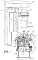
- a box 1 may contain nuclear fuel powder is placed on a support. It includes an upper lid 3 surrounded by a rim 4 rising a little above him.
- the machine for opening the box 1 comprises a tool body 5 mounted on a frame 6 and movable relative to it in the vertical direction by a press 7; the tool body 5 is guided by the adjustment of a rib 9 which forms part of it in a slide 8 constructed on the frame 6.
- the tool body 5 comprises a plate 10 at a lower part, which carries a group of peripheral columns 11 directed downwards and at the lower end of which is screwed a guide ring 12.
- a movable flange 13 slides on the columns 11 between the plate 10 and the guide ring 12.
- a tool 14 whose active part is a ring gear 15 pointing downwards is surrounded by the guide ring 12 and the movable flange 13, and it is retained by the plate 10 by means of mounting screws 16.
- Springs 17 are engaged around the peripheral columns 11 and bring the mobile flange 13 down. In the center of the device, under the tool 14, extends a piston 18 whose bottom carries a magnet 19.
- the piston 18 is movable in a bore of the plate 10 lined with a bearing 20 to a lower position of stop; a spring 21 compressed between the bearing 20 and the magnet 19 returns the piston 18 to the lower position but does not prevent it being raised towards the plate 10. It also slides in a bore of the plate 10 a pin 22 extending to under the magnet 19 when a lower stop position is reached. Its upper end then remains below an induction sensor 23 mounted on the upper face of the plate 10. There is another pin 24, actuated by an electromagnet 25 mounted on the top of the tool body 5, also extending vertically, through the piston 18, but without however coming below the magnet 19 in the usual position.
- the tool body 5 When the box 1 is placed on the support 2, the tool body 5 is lowered by the press 7.
- the guide ring 12 engages the upper edge 4 of the box 1 by a chamfered inner face 26 stripped towards the bottom and center of the box 1 relative to the tool body 5.
- the upper edge 4 finally hits a bottom face 27 of the movable flange 13 which holds the box 1 in place, and the rest of the movement descending the tool body 5 is accompanied by a compression of the springs 17, the flange 13 movable abutting against the upper edge 4, remaining at the same altitude while the rest of the tool body 5 continues to descend.
- the ring gear 15 reaches the cover 3 and pierces it until it is cut.
- the magnet 19 comes into contact with the cut-off cover 3 and grasps it.
- the pin 22 is raised by the cover 3 until its upper end comes within range of the inductive sensor 23, so that the presence of a lid 3 attached to the magnet 19 is proven.
- the machine described so far is improved by means of the invention.
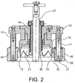
- the tool body is changed. He understands, according to figure 2 , in addition to the plate 10, the peripheral columns 11, the springs 17 and the tool 14, which are unchanged, a new guide ring 30, which is here movable between a lower abutment end, at the end of the peripheral columns 11, and the plate 10.
- Its inner face comprises both a tapered chamfered face 32 downwardly, intended to center the upper edge 4 of the box 1, and a stop face 33 directed downwards that the upper edge 4 must reach in order to be retained in place.
- the guide ring 30 is guided by bearings with rolling elements mounted on the peripheral columns 11 and plain bearings 35.
- the high-level guide face between the tool 14 and the mobile flange 13 is here suppressed, and a wide clearance extends between the tool 14 and the lower guide ring 30.
- the tool body further comprises the movable piston 18 and the springs 21 which recall it downwards.
- the magnet 19 is here absent and the piston 18 carries a lower collar 36 simple, without magnetic property.
- an ejection pin 37 is shown which passes vertically through the plate 10 and the piston 18.
- the operation of the device is as follows.
- the box 1 is still placed on the support 2.
- the press still similar to that of the previous machine down the tool body down.
- the lower guide ring 30 centers the box 1 by its bevel face 32 and rises as soon as the lower edge 4 has reached the abutment face 33, but the tool 14 continues to descend and cuts the lid 3
- the piston 18 also continues to descend and pushes the lid 3 cut towards the bottom of the box 1 despite the spring arrow 21.
- the tool body is raised, it returns to the position of the figure 2 and the pin 37 projecting under the tool 14 and the piston 18 detaches the lid 3 if it had been retained.
- the cover 3 remains in the box 1.
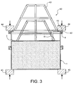
- the emptying is carried out as indicated in connection with the figure 3 .
- a so-called lower flange 40 receives the box 1.
- a flange 41 is placed on the upper edge 4 and extends around it by a flange 42; the remainder of the lower flange 40 is a lattice network 43 of bars comprising a lug 51 extending beyond the rim 41.
- the lug 51 has a peripheral position which allows it to tilt the lid 3 cut into lowering it to where it is.
- the box 1 and the lower flange 40 are held pressed against one another by jaws 44 and 45 forming part of a turning machine which is not further shown.
- the assembly can however tilt so that the lower flange 40 comes under the box 1.
- the powder pushes the cover 3, which tilts when it touches the lug 51 and opens the box 1.
- the inclination of the lid 3 allows the powder contained in the box 1 to flow without difficulty through the opening thus formed.
- the lid is retained by the la
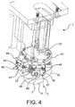
- FIG. 4 Another aspect of the invention will be described by means of the figure 4 .
- the presence of the box 1 under the press is detected by the depression of the lower guide ring 30. This depression is measured by inductive sensors 46.
- they are not mounted rigidly relative to the plate 10, but on adjustable heads 47 connected to fixed heads 48, screwed to the plate 10, by micrometer screws 49 which can independently adjust their level according to calibrations. Compressed springs 50 between the heads 47 and 48 maintain their spacing at the setting value. Safer detection can thus be obtained.
Landscapes
- Engineering & Computer Science (AREA)
- Mechanical Engineering (AREA)
- Control And Other Processes For Unpacking Of Materials (AREA)
- Devices For Opening Bottles Or Cans (AREA)
- Automatic Assembly (AREA)
Applications Claiming Priority (2)
| Application Number | Priority Date | Filing Date | Title |
|---|---|---|---|
| FR0857003A FR2937027B1 (fr) | 2008-10-15 | 2008-10-15 | Machine d'ouverture de couvercle de boite et procede de vidage de boite |
| PCT/EP2009/063313 WO2010043600A1 (fr) | 2008-10-15 | 2009-10-13 | Machine d'ouverture de couvercle de boite et procede de vidage de boite |
Publications (2)
| Publication Number | Publication Date |
|---|---|
| EP2344411A1 EP2344411A1 (fr) | 2011-07-20 |
| EP2344411B1 true EP2344411B1 (fr) | 2016-04-06 |
Family
ID=40675149
Family Applications (1)
| Application Number | Title | Priority Date | Filing Date |
|---|---|---|---|
| EP09783965.8A Active EP2344411B1 (fr) | 2008-10-15 | 2009-10-13 | Machine d'ouverture de couvercle de boite et procede de vidage de boite |
Country Status (8)
| Country | Link |
|---|---|
| US (1) | US20110232111A1 (enExample) |
| EP (1) | EP2344411B1 (enExample) |
| JP (1) | JP5490810B2 (enExample) |
| CN (1) | CN102177084A (enExample) |
| FR (1) | FR2937027B1 (enExample) |
| RU (1) | RU2503612C2 (enExample) |
| WO (1) | WO2010043600A1 (enExample) |
| ZA (1) | ZA201101164B (enExample) |
Families Citing this family (5)
| Publication number | Priority date | Publication date | Assignee | Title |
|---|---|---|---|---|
| FR2984790B1 (fr) | 2011-12-22 | 2014-02-21 | Areva Nc | Dispositif de manipulation d'objets en boites a gants |
| FR2990933B1 (fr) | 2012-05-22 | 2014-07-04 | Areva Nc | Dispositif de stockage indexe en position |
| CN104973549A (zh) * | 2014-04-09 | 2015-10-14 | 梁策初 | 安全秒开罐头机 |
| CN103964357A (zh) * | 2014-04-25 | 2014-08-06 | 徐存然 | 一种多功能启开器 |
| US11186015B2 (en) * | 2019-04-30 | 2021-11-30 | Creative Green Designs Llc | Pod processing device |
Family Cites Families (15)
| Publication number | Priority date | Publication date | Assignee | Title |
|---|---|---|---|---|
| GB235711A (en) * | 1924-06-13 | 1925-06-25 | Gilbert Hallam | Improvements in appliances for opening tins, and their like, in one operation |
| US2929138A (en) * | 1958-03-03 | 1960-03-22 | Hill David Earl | Electrical can opener |
| JPS526678B2 (enExample) * | 1971-12-21 | 1977-02-23 | ||
| GB1344424A (en) * | 1972-07-31 | 1974-01-23 | Optrex Ltd | Can opener and method of opening cans |
| JPS57122737U (enExample) * | 1981-01-23 | 1982-07-30 | ||
| JP3088955B2 (ja) * | 1996-07-11 | 2000-09-18 | 呉羽環境株式会社 | ドラム缶切り装置 |
| CN2316306Y (zh) * | 1997-12-24 | 1999-04-28 | 骏华开发企业有限公司 | 一种双柄侧开式开罐器 |
| US6098293A (en) * | 1998-07-23 | 2000-08-08 | James H. Bronner | Can opener with rotating bottom support |
| JP2001062528A (ja) * | 1999-08-24 | 2001-03-13 | Amada Co Ltd | タレットパンチプレス |
| GB2362367B (en) * | 2000-05-19 | 2002-03-27 | Shun So | Can opener |
| CN2437658Y (zh) * | 2000-09-07 | 2001-07-04 | 王渝 | 罐筒开启装置 |
| US6739061B1 (en) * | 2002-09-13 | 2004-05-25 | Sherry L. Montel | Automatic can opener |
| FR2845371B1 (fr) * | 2002-10-08 | 2005-08-05 | Cogema | Machine d'ouverture de couvercle de boite |
| US7574808B2 (en) * | 2005-12-12 | 2009-08-18 | Daka Research Inc. (Br. Virg. Isl Corp.) | Mechanism for can opener |
| JP2007245207A (ja) * | 2006-03-16 | 2007-09-27 | Daihatsu Motor Co Ltd | パンチユニット |
-
2008
- 2008-10-15 FR FR0857003A patent/FR2937027B1/fr not_active Expired - Fee Related
-
2009
- 2009-10-13 RU RU2011119419/12A patent/RU2503612C2/ru not_active IP Right Cessation
- 2009-10-13 US US13/123,883 patent/US20110232111A1/en not_active Abandoned
- 2009-10-13 CN CN2009801399054A patent/CN102177084A/zh active Pending
- 2009-10-13 EP EP09783965.8A patent/EP2344411B1/fr active Active
- 2009-10-13 WO PCT/EP2009/063313 patent/WO2010043600A1/fr not_active Ceased
- 2009-10-13 JP JP2011531465A patent/JP5490810B2/ja active Active
-
2011
- 2011-02-14 ZA ZA2011/01164A patent/ZA201101164B/en unknown
Also Published As
| Publication number | Publication date |
|---|---|
| US20110232111A1 (en) | 2011-09-29 |
| WO2010043600A1 (fr) | 2010-04-22 |
| FR2937027A1 (fr) | 2010-04-16 |
| FR2937027B1 (fr) | 2010-12-03 |
| ZA201101164B (en) | 2011-10-26 |
| RU2011119419A (ru) | 2012-11-27 |
| JP2012505800A (ja) | 2012-03-08 |
| CN102177084A (zh) | 2011-09-07 |
| JP5490810B2 (ja) | 2014-05-14 |
| RU2503612C2 (ru) | 2014-01-10 |
| EP2344411A1 (fr) | 2011-07-20 |
Similar Documents
| Publication | Publication Date | Title |
|---|---|---|
| EP2344411B1 (fr) | Machine d'ouverture de couvercle de boite et procede de vidage de boite | |
| EP1967269B1 (fr) | Dispositif de positionnement automatique assisté d'une enceinte de chauffage contre un ballon de distillation | |
| US12269545B2 (en) | Self-adjusting bike rack | |
| EP0993244A1 (fr) | Ecran de blindage électromagnétique et substrat support de circuit équipé d'un tel écran | |
| FR2768359A1 (fr) | Appareil de coupe/rupture | |
| FR2747186A1 (fr) | Machine de jaugeage a cylindre | |
| EP3381596B1 (fr) | Machine et procede d'usinage par electroerosion de pompe gerotor | |
| EP2223124B1 (fr) | Dispositif de prelevement de liquide dans un tube ferme par un bouchon | |
| EP1459822B1 (fr) | Outillage permettant l'ébarbage de pièces mécaniques forgées | |
| EP0274962B1 (fr) | Machine automatique verticale pour la coupe du verre | |
| EP2794083A1 (fr) | Support de capteur pour un reacteur en cours de chargement | |
| EP4464611A1 (fr) | Système de dépose de supports publicitaires sur des récipients | |
| EP0064925A1 (fr) | Dispositif de verrouillage d'un support de roue de secours, sous le plancher d'un véhicule | |
| EP2803593B1 (fr) | Procédé et installation pour manchonner un objet | |
| CH648268A5 (en) | Lift for vehicles | |
| FR2574773A1 (fr) | Chariot de reception et de transport d'une piece de tricot pour metiers circulaires | |
| EP3978704B1 (fr) | Installation de maintenance de véhicule ferroviaire, atelier de maintenance et procédé d'utilisation d'une installation de maintenance associés | |
| EP0105532B1 (fr) | Installation destinée à délivrer un à un des pots de fleurs à une machine destinée à remplir ceux-ci | |
| EP3919243A1 (fr) | Trancheuse à pain avec un dispositif de nettoyage et procédé correspondant | |
| FR2845371A1 (fr) | Machine d'ouverture de couvercle de boite | |
| FR2631563A1 (fr) | Procede et dispositif de compactage des pneumatiques | |
| BE1031571B1 (fr) | Trancheuse de pain | |
| EP0490757B1 (fr) | Procédé et dispositif pour le prélèvement automatique d'un échantillon de matériau lors de sa coulée dans un conteneur | |
| CH432884A (fr) | Dispositif pour l'enrobage d'un échantillon de matière solide | |
| FR2505526A1 (fr) | Controleur de pieces de monnaie |
Legal Events
| Date | Code | Title | Description |
|---|---|---|---|
| PUAI | Public reference made under article 153(3) epc to a published international application that has entered the european phase |
Free format text: ORIGINAL CODE: 0009012 |
|
| 17P | Request for examination filed |
Effective date: 20110412 |
|
| AK | Designated contracting states |
Kind code of ref document: A1 Designated state(s): AT BE BG CH CY CZ DE DK EE ES FI FR GB GR HR HU IE IS IT LI LT LU LV MC MK MT NL NO PL PT RO SE SI SK SM TR |
|
| AX | Request for extension of the european patent |
Extension state: AL BA RS |
|
| DAX | Request for extension of the european patent (deleted) | ||
| GRAP | Despatch of communication of intention to grant a patent |
Free format text: ORIGINAL CODE: EPIDOSNIGR1 |
|
| INTG | Intention to grant announced |
Effective date: 20151012 |
|
| GRAS | Grant fee paid |
Free format text: ORIGINAL CODE: EPIDOSNIGR3 |
|
| GRAA | (expected) grant |
Free format text: ORIGINAL CODE: 0009210 |
|
| AK | Designated contracting states |
Kind code of ref document: B1 Designated state(s): AT BE BG CH CY CZ DE DK EE ES FI FR GB GR HR HU IE IS IT LI LT LU LV MC MK MT NL NO PL PT RO SE SI SK SM TR |
|
| REG | Reference to a national code |
Ref country code: GB Ref legal event code: FG4D Free format text: NOT ENGLISH |
|
| REG | Reference to a national code |
Ref country code: AT Ref legal event code: REF Ref document number: 787598 Country of ref document: AT Kind code of ref document: T Effective date: 20160415 Ref country code: CH Ref legal event code: EP |
|
| REG | Reference to a national code |
Ref country code: IE Ref legal event code: FG4D Free format text: LANGUAGE OF EP DOCUMENT: FRENCH |
|
| REG | Reference to a national code |
Ref country code: DE Ref legal event code: R096 Ref document number: 602009037542 Country of ref document: DE |
|
| REG | Reference to a national code |
Ref country code: LT Ref legal event code: MG4D Ref country code: NL Ref legal event code: MP Effective date: 20160406 |
|
| REG | Reference to a national code |
Ref country code: AT Ref legal event code: MK05 Ref document number: 787598 Country of ref document: AT Kind code of ref document: T Effective date: 20160406 |
|
| PG25 | Lapsed in a contracting state [announced via postgrant information from national office to epo] |
Ref country code: NL Free format text: LAPSE BECAUSE OF FAILURE TO SUBMIT A TRANSLATION OF THE DESCRIPTION OR TO PAY THE FEE WITHIN THE PRESCRIBED TIME-LIMIT Effective date: 20160406 |
|
| REG | Reference to a national code |
Ref country code: FR Ref legal event code: PLFP Year of fee payment: 8 |
|
| PG25 | Lapsed in a contracting state [announced via postgrant information from national office to epo] |
Ref country code: NO Free format text: LAPSE BECAUSE OF FAILURE TO SUBMIT A TRANSLATION OF THE DESCRIPTION OR TO PAY THE FEE WITHIN THE PRESCRIBED TIME-LIMIT Effective date: 20160706 Ref country code: IS Free format text: LAPSE BECAUSE OF FAILURE TO SUBMIT A TRANSLATION OF THE DESCRIPTION OR TO PAY THE FEE WITHIN THE PRESCRIBED TIME-LIMIT Effective date: 20160806 Ref country code: PL Free format text: LAPSE BECAUSE OF FAILURE TO SUBMIT A TRANSLATION OF THE DESCRIPTION OR TO PAY THE FEE WITHIN THE PRESCRIBED TIME-LIMIT Effective date: 20160406 Ref country code: LT Free format text: LAPSE BECAUSE OF FAILURE TO SUBMIT A TRANSLATION OF THE DESCRIPTION OR TO PAY THE FEE WITHIN THE PRESCRIBED TIME-LIMIT Effective date: 20160406 Ref country code: FI Free format text: LAPSE BECAUSE OF FAILURE TO SUBMIT A TRANSLATION OF THE DESCRIPTION OR TO PAY THE FEE WITHIN THE PRESCRIBED TIME-LIMIT Effective date: 20160406 |
|
| PG25 | Lapsed in a contracting state [announced via postgrant information from national office to epo] |
Ref country code: PT Free format text: LAPSE BECAUSE OF FAILURE TO SUBMIT A TRANSLATION OF THE DESCRIPTION OR TO PAY THE FEE WITHIN THE PRESCRIBED TIME-LIMIT Effective date: 20160808 Ref country code: AT Free format text: LAPSE BECAUSE OF FAILURE TO SUBMIT A TRANSLATION OF THE DESCRIPTION OR TO PAY THE FEE WITHIN THE PRESCRIBED TIME-LIMIT Effective date: 20160406 Ref country code: HR Free format text: LAPSE BECAUSE OF FAILURE TO SUBMIT A TRANSLATION OF THE DESCRIPTION OR TO PAY THE FEE WITHIN THE PRESCRIBED TIME-LIMIT Effective date: 20160406 Ref country code: SE Free format text: LAPSE BECAUSE OF FAILURE TO SUBMIT A TRANSLATION OF THE DESCRIPTION OR TO PAY THE FEE WITHIN THE PRESCRIBED TIME-LIMIT Effective date: 20160406 Ref country code: GR Free format text: LAPSE BECAUSE OF FAILURE TO SUBMIT A TRANSLATION OF THE DESCRIPTION OR TO PAY THE FEE WITHIN THE PRESCRIBED TIME-LIMIT Effective date: 20160707 Ref country code: LV Free format text: LAPSE BECAUSE OF FAILURE TO SUBMIT A TRANSLATION OF THE DESCRIPTION OR TO PAY THE FEE WITHIN THE PRESCRIBED TIME-LIMIT Effective date: 20160406 Ref country code: ES Free format text: LAPSE BECAUSE OF FAILURE TO SUBMIT A TRANSLATION OF THE DESCRIPTION OR TO PAY THE FEE WITHIN THE PRESCRIBED TIME-LIMIT Effective date: 20160406 |
|
| PG25 | Lapsed in a contracting state [announced via postgrant information from national office to epo] |
Ref country code: IT Free format text: LAPSE BECAUSE OF FAILURE TO SUBMIT A TRANSLATION OF THE DESCRIPTION OR TO PAY THE FEE WITHIN THE PRESCRIBED TIME-LIMIT Effective date: 20160406 |
|
| REG | Reference to a national code |
Ref country code: DE Ref legal event code: R097 Ref document number: 602009037542 Country of ref document: DE |
|
| PG25 | Lapsed in a contracting state [announced via postgrant information from national office to epo] |
Ref country code: SK Free format text: LAPSE BECAUSE OF FAILURE TO SUBMIT A TRANSLATION OF THE DESCRIPTION OR TO PAY THE FEE WITHIN THE PRESCRIBED TIME-LIMIT Effective date: 20160406 Ref country code: DK Free format text: LAPSE BECAUSE OF FAILURE TO SUBMIT A TRANSLATION OF THE DESCRIPTION OR TO PAY THE FEE WITHIN THE PRESCRIBED TIME-LIMIT Effective date: 20160406 Ref country code: CZ Free format text: LAPSE BECAUSE OF FAILURE TO SUBMIT A TRANSLATION OF THE DESCRIPTION OR TO PAY THE FEE WITHIN THE PRESCRIBED TIME-LIMIT Effective date: 20160406 Ref country code: EE Free format text: LAPSE BECAUSE OF FAILURE TO SUBMIT A TRANSLATION OF THE DESCRIPTION OR TO PAY THE FEE WITHIN THE PRESCRIBED TIME-LIMIT Effective date: 20160406 Ref country code: RO Free format text: LAPSE BECAUSE OF FAILURE TO SUBMIT A TRANSLATION OF THE DESCRIPTION OR TO PAY THE FEE WITHIN THE PRESCRIBED TIME-LIMIT Effective date: 20160406 |
|
| PLBE | No opposition filed within time limit |
Free format text: ORIGINAL CODE: 0009261 |
|
| STAA | Information on the status of an ep patent application or granted ep patent |
Free format text: STATUS: NO OPPOSITION FILED WITHIN TIME LIMIT |
|
| PG25 | Lapsed in a contracting state [announced via postgrant information from national office to epo] |
Ref country code: SM Free format text: LAPSE BECAUSE OF FAILURE TO SUBMIT A TRANSLATION OF THE DESCRIPTION OR TO PAY THE FEE WITHIN THE PRESCRIBED TIME-LIMIT Effective date: 20160406 Ref country code: BE Free format text: LAPSE BECAUSE OF NON-PAYMENT OF DUE FEES Effective date: 20161031 |
|
| 26N | No opposition filed |
Effective date: 20170110 |
|
| REG | Reference to a national code |
Ref country code: DE Ref legal event code: R119 Ref document number: 602009037542 Country of ref document: DE |
|
| PG25 | Lapsed in a contracting state [announced via postgrant information from national office to epo] |
Ref country code: SI Free format text: LAPSE BECAUSE OF FAILURE TO SUBMIT A TRANSLATION OF THE DESCRIPTION OR TO PAY THE FEE WITHIN THE PRESCRIBED TIME-LIMIT Effective date: 20160406 |
|
| REG | Reference to a national code |
Ref country code: CH Ref legal event code: PL |
|
| REG | Reference to a national code |
Ref country code: IE Ref legal event code: MM4A |
|
| PG25 | Lapsed in a contracting state [announced via postgrant information from national office to epo] |
Ref country code: DE Free format text: LAPSE BECAUSE OF NON-PAYMENT OF DUE FEES Effective date: 20170503 Ref country code: LI Free format text: LAPSE BECAUSE OF NON-PAYMENT OF DUE FEES Effective date: 20161031 Ref country code: CH Free format text: LAPSE BECAUSE OF NON-PAYMENT OF DUE FEES Effective date: 20161031 |
|
| PG25 | Lapsed in a contracting state [announced via postgrant information from national office to epo] |
Ref country code: LU Free format text: LAPSE BECAUSE OF NON-PAYMENT OF DUE FEES Effective date: 20161013 |
|
| REG | Reference to a national code |
Ref country code: FR Ref legal event code: PLFP Year of fee payment: 9 |
|
| PG25 | Lapsed in a contracting state [announced via postgrant information from national office to epo] |
Ref country code: IE Free format text: LAPSE BECAUSE OF NON-PAYMENT OF DUE FEES Effective date: 20161013 |
|
| REG | Reference to a national code |
Ref country code: BE Ref legal event code: MM Effective date: 20161031 |
|
| PG25 | Lapsed in a contracting state [announced via postgrant information from national office to epo] |
Ref country code: CY Free format text: LAPSE BECAUSE OF FAILURE TO SUBMIT A TRANSLATION OF THE DESCRIPTION OR TO PAY THE FEE WITHIN THE PRESCRIBED TIME-LIMIT Effective date: 20160406 Ref country code: HU Free format text: LAPSE BECAUSE OF FAILURE TO SUBMIT A TRANSLATION OF THE DESCRIPTION OR TO PAY THE FEE WITHIN THE PRESCRIBED TIME-LIMIT; INVALID AB INITIO Effective date: 20091013 |
|
| PG25 | Lapsed in a contracting state [announced via postgrant information from national office to epo] |
Ref country code: TR Free format text: LAPSE BECAUSE OF FAILURE TO SUBMIT A TRANSLATION OF THE DESCRIPTION OR TO PAY THE FEE WITHIN THE PRESCRIBED TIME-LIMIT Effective date: 20160406 Ref country code: MC Free format text: LAPSE BECAUSE OF FAILURE TO SUBMIT A TRANSLATION OF THE DESCRIPTION OR TO PAY THE FEE WITHIN THE PRESCRIBED TIME-LIMIT Effective date: 20160406 Ref country code: MT Free format text: LAPSE BECAUSE OF FAILURE TO SUBMIT A TRANSLATION OF THE DESCRIPTION OR TO PAY THE FEE WITHIN THE PRESCRIBED TIME-LIMIT Effective date: 20160406 Ref country code: MK Free format text: LAPSE BECAUSE OF FAILURE TO SUBMIT A TRANSLATION OF THE DESCRIPTION OR TO PAY THE FEE WITHIN THE PRESCRIBED TIME-LIMIT Effective date: 20160406 |
|
| PG25 | Lapsed in a contracting state [announced via postgrant information from national office to epo] |
Ref country code: BG Free format text: LAPSE BECAUSE OF FAILURE TO SUBMIT A TRANSLATION OF THE DESCRIPTION OR TO PAY THE FEE WITHIN THE PRESCRIBED TIME-LIMIT Effective date: 20160406 |
|
| REG | Reference to a national code |
Ref country code: FR Ref legal event code: PLFP Year of fee payment: 10 |
|
| REG | Reference to a national code |
Ref country code: GB Ref legal event code: 732E Free format text: REGISTERED BETWEEN 20220217 AND 20220223 |
|
| PGFP | Annual fee paid to national office [announced via postgrant information from national office to epo] |
Ref country code: GB Payment date: 20241024 Year of fee payment: 16 |
|
| PGFP | Annual fee paid to national office [announced via postgrant information from national office to epo] |
Ref country code: FR Payment date: 20241024 Year of fee payment: 16 |