EP2344381B1 - Entree d'air d'un moteur d'avion a helices propulsives non carenees - Google Patents
Entree d'air d'un moteur d'avion a helices propulsives non carenees Download PDFInfo
- Publication number
- EP2344381B1 EP2344381B1 EP20090760929 EP09760929A EP2344381B1 EP 2344381 B1 EP2344381 B1 EP 2344381B1 EP 20090760929 EP20090760929 EP 20090760929 EP 09760929 A EP09760929 A EP 09760929A EP 2344381 B1 EP2344381 B1 EP 2344381B1
- Authority
- EP
- European Patent Office
- Prior art keywords
- air inlet
- engine
- pylon
- axis
- leading edge
- Prior art date
- Legal status (The legal status is an assumption and is not a legal conclusion. Google has not performed a legal analysis and makes no representation as to the accuracy of the status listed.)
- Active
Links
- 238000011144 upstream manufacturing Methods 0.000 claims description 21
- 239000003380 propellant Substances 0.000 description 7
- 230000010354 integration Effects 0.000 description 5
- 239000007789 gas Substances 0.000 description 3
- 238000000034 method Methods 0.000 description 3
- 230000001141 propulsive effect Effects 0.000 description 3
- 238000002485 combustion reaction Methods 0.000 description 2
- 229960001868 propulsives Drugs 0.000 description 2
- 230000004323 axial length Effects 0.000 description 1
- 230000005465 channeling Effects 0.000 description 1
- 239000000567 combustion gas Substances 0.000 description 1
- 238000005530 etching Methods 0.000 description 1
- 239000000446 fuel Substances 0.000 description 1
- 238000009434 installation Methods 0.000 description 1
Images

Classifications
-
- B—PERFORMING OPERATIONS; TRANSPORTING
- B64—AIRCRAFT; AVIATION; COSMONAUTICS
- B64D—EQUIPMENT FOR FITTING IN OR TO AIRCRAFT; FLIGHT SUITS; PARACHUTES; ARRANGEMENT OR MOUNTING OF POWER PLANTS OR PROPULSION TRANSMISSIONS IN AIRCRAFT
- B64D27/00—Arrangement or mounting of power plants in aircraft; Aircraft characterised by the type or position of power plants
- B64D27/02—Aircraft characterised by the type or position of power plants
- B64D27/10—Aircraft characterised by the type or position of power plants of gas-turbine type
- B64D27/14—Aircraft characterised by the type or position of power plants of gas-turbine type within, or attached to, fuselages
-
- F—MECHANICAL ENGINEERING; LIGHTING; HEATING; WEAPONS; BLASTING
- F02—COMBUSTION ENGINES; HOT-GAS OR COMBUSTION-PRODUCT ENGINE PLANTS
- F02C—GAS-TURBINE PLANTS; AIR INTAKES FOR JET-PROPULSION PLANTS; CONTROLLING FUEL SUPPLY IN AIR-BREATHING JET-PROPULSION PLANTS
- F02C7/00—Features, components parts, details or accessories, not provided for in, or of interest apart form groups F02C1/00 - F02C6/00; Air intakes for jet-propulsion plants
- F02C7/04—Air intakes for gas-turbine plants or jet-propulsion plants
- F02C7/042—Air intakes for gas-turbine plants or jet-propulsion plants having variable geometry
-
- B—PERFORMING OPERATIONS; TRANSPORTING
- B64—AIRCRAFT; AVIATION; COSMONAUTICS
- B64D—EQUIPMENT FOR FITTING IN OR TO AIRCRAFT; FLIGHT SUITS; PARACHUTES; ARRANGEMENT OR MOUNTING OF POWER PLANTS OR PROPULSION TRANSMISSIONS IN AIRCRAFT
- B64D27/00—Arrangement or mounting of power plants in aircraft; Aircraft characterised by the type or position of power plants
- B64D27/02—Aircraft characterised by the type or position of power plants
- B64D27/026—Aircraft characterised by the type or position of power plants comprising different types of power plants, e.g. combination of a piston engine and a gas-turbine
-
- B—PERFORMING OPERATIONS; TRANSPORTING
- B64—AIRCRAFT; AVIATION; COSMONAUTICS
- B64D—EQUIPMENT FOR FITTING IN OR TO AIRCRAFT; FLIGHT SUITS; PARACHUTES; ARRANGEMENT OR MOUNTING OF POWER PLANTS OR PROPULSION TRANSMISSIONS IN AIRCRAFT
- B64D29/00—Power-plant nacelles, fairings, or cowlings
- B64D29/04—Power-plant nacelles, fairings, or cowlings associated with fuselages
-
- B—PERFORMING OPERATIONS; TRANSPORTING
- B64—AIRCRAFT; AVIATION; COSMONAUTICS
- B64D—EQUIPMENT FOR FITTING IN OR TO AIRCRAFT; FLIGHT SUITS; PARACHUTES; ARRANGEMENT OR MOUNTING OF POWER PLANTS OR PROPULSION TRANSMISSIONS IN AIRCRAFT
- B64D33/00—Arrangements in aircraft of power plant parts or auxiliaries not otherwise provided for
- B64D33/02—Arrangements in aircraft of power plant parts or auxiliaries not otherwise provided for of combustion air intakes
-
- B—PERFORMING OPERATIONS; TRANSPORTING
- B64—AIRCRAFT; AVIATION; COSMONAUTICS
- B64D—EQUIPMENT FOR FITTING IN OR TO AIRCRAFT; FLIGHT SUITS; PARACHUTES; ARRANGEMENT OR MOUNTING OF POWER PLANTS OR PROPULSION TRANSMISSIONS IN AIRCRAFT
- B64D27/00—Arrangement or mounting of power plants in aircraft; Aircraft characterised by the type or position of power plants
- B64D2027/005—Aircraft with an unducted turbofan comprising contra-rotating rotors, e.g. contra-rotating open rotors [CROR]
-
- B—PERFORMING OPERATIONS; TRANSPORTING
- B64—AIRCRAFT; AVIATION; COSMONAUTICS
- B64D—EQUIPMENT FOR FITTING IN OR TO AIRCRAFT; FLIGHT SUITS; PARACHUTES; ARRANGEMENT OR MOUNTING OF POWER PLANTS OR PROPULSION TRANSMISSIONS IN AIRCRAFT
- B64D33/00—Arrangements in aircraft of power plant parts or auxiliaries not otherwise provided for
- B64D33/02—Arrangements in aircraft of power plant parts or auxiliaries not otherwise provided for of combustion air intakes
- B64D2033/0266—Arrangements in aircraft of power plant parts or auxiliaries not otherwise provided for of combustion air intakes specially adapted for particular type of power plants
- B64D2033/0293—Arrangements in aircraft of power plant parts or auxiliaries not otherwise provided for of combustion air intakes specially adapted for particular type of power plants for turboprop engines
-
- Y—GENERAL TAGGING OF NEW TECHNOLOGICAL DEVELOPMENTS; GENERAL TAGGING OF CROSS-SECTIONAL TECHNOLOGIES SPANNING OVER SEVERAL SECTIONS OF THE IPC; TECHNICAL SUBJECTS COVERED BY FORMER USPC CROSS-REFERENCE ART COLLECTIONS [XRACs] AND DIGESTS
- Y02—TECHNOLOGIES OR APPLICATIONS FOR MITIGATION OR ADAPTATION AGAINST CLIMATE CHANGE
- Y02T—CLIMATE CHANGE MITIGATION TECHNOLOGIES RELATED TO TRANSPORTATION
- Y02T50/00—Aeronautics or air transport
- Y02T50/60—Efficient propulsion technologies, e.g. for aircraft
-
- Y—GENERAL TAGGING OF NEW TECHNOLOGICAL DEVELOPMENTS; GENERAL TAGGING OF CROSS-SECTIONAL TECHNOLOGIES SPANNING OVER SEVERAL SECTIONS OF THE IPC; TECHNICAL SUBJECTS COVERED BY FORMER USPC CROSS-REFERENCE ART COLLECTIONS [XRACs] AND DIGESTS
- Y10—TECHNICAL SUBJECTS COVERED BY FORMER USPC
- Y10T—TECHNICAL SUBJECTS COVERED BY FORMER US CLASSIFICATION
- Y10T137/00—Fluid handling
- Y10T137/0536—Highspeed fluid intake means [e.g., jet engine intake]
Definitions
- the present invention relates to an air intake of an aircraft engine, and in particular an aircraft engine propeller propellant propeller unfaced (in English "open-rotor pusher” or “pusher unducted fan”).
- An engine of this type (such as that described in the application FR-A1-2 892 705 ) comprises two counter-rotating turbines each of which is integral in rotation with a propeller located outside the nacelle of the engine, the two propellers being arranged coaxially one behind the other at the downstream end of the engine.
- This engine is fixed to an aircraft by means of a pylon which extends substantially radially with respect to the longitudinal axis of the engine and whose radially inner end is connected to the upstream end of the engine nacelle, that is to say at the air intake of this engine.
- the pylon must be at a sufficient axial distance from the propellers and the upstream end or leading edge of the air inlet, in particular for aerodynamic reasons. In the current technique, it is necessary to extend the air intake of the engine in the axial direction to allow the connection of the pylon to the air inlet and the engine, resulting in a significant increase in the mass of the nacelle and the drag generated by it in operation.
- the air intake of an engine with propeller propellers not keeled is generally axisymmetric in the current technique, that is to say that its leading edge is inscribed in a plane perpendicular to the axis of the engine.
- An axisymmetric air inlet has a constant UD ratio on its circumference, L being the local length of the air inlet, measured parallel to the axis of the engine between a point of the leading edge and a plane passing through the plane. of the motor input wheel, and D being the internal diameter of the air inlet, at this input wheel.
- the air inlet When the air inlet is not axisymmetric, its leading edge defines an approximately planar surface called the capture section (in English "hilite” or “high light”).
- the capture section in English "hilite” or "high light”
- an overall air inlet length is defined which is equal to the distance between the transverse plane at the level of the motor inlet wheel and the point of intersection between the capture of the air inlet and the motor shaft.
- an air inlet of this type is defined by a "global” L / D ratio (overall length over diameter) and has a “local” (local length to diameter) UD ratio that varies linearly over the circumference of the airfoil. air inlet.
- This particular shape of the air intake bevel essentially has the function of limiting the noise emitted by the engine upstream, towards the ground. Indeed, the lower part of greater length of the air intake beveled allows to reflect and deflect upward a greater part of the noise emitted upstream by the engine in operation.
- This type of engine is generally fixed under the wing of an aircraft by means of a pylon which is connected to the air inlet at its upper part of smaller length.
- the invention aims in particular to provide a simple, effective and economical solution to the aforementioned problems related to the integration of a pylon to the air intake of an aircraft engine with propellant propellers not careened.
- an air intake of an aircraft engine of the propellant propeller propeller type intended to be connected by a pylon to the fuselage of an airplane, characterized in that the local length of the entrance of air, measured parallel to the axis of the engine between a point of the leading edge of the air intake and a transverse plane located at an input wheel of the engine compressor, is greater in the zone of the air inlet connected to the pylon and weaker in the area of the air inlet opposite the pylon.
- the local length of the air inlet according to the invention varies on the circumference of the air inlet, being maximum in the zone connected to the pylon, and minimum in the opposite zone, contrary to the prior art in which the upper part of shorter length of the air intake bevel is connected to the latching pylon.
- the shape and the dimensions of the zone of the air inlet connected to the pylon are optimized according to the dimensioning of the pylon, while the shape and the dimensions of the rest of the air inlet are optimized independently of this pylon, in order to limit the mass of the air intake and the drag generated by the nacelle of the engine in operation.
- the variation of the local length of the air inlet is non-linear on the circumference of the air inlet. Unlike the prior art, the capturing section of the air inlet is not flat and it is not possible to define the length of the air inlet according to the invention by a "global" UD ratio. ".
- the "local" L / D ratio of the air inlet according to the invention preferably varies between about 2.5 and 0.9 between the zone connected to the pylon and the opposite zone of the air inlet, L being the local length of the air inlet, and D being its inside diameter, L and D being measured as indicated above.
- the leading edge of the air inlet has a substantially dihedral contour.
- the angle at the top of the dihedral is for example between 90 and 175 °.
- the top of the dihedral may have a concave rounded shape on the side of the dihedral opening.
- the sides of the dihedron may be substantially rectilinear or curved concave or convex.
- the air inlet is symmetrical with respect to a median plane passing through the axis of the pylon and the axis of the engine.
- the edge etching of the air inlet according to the invention then defines two dihedrons located on either side of this median plane and connected by rounded.
- the upstream sides of these two dihedrals extend in a first air inlet plane which is inclined with respect to the axis of the engine, and the downstream sides of the dihedrals extend in a second inlet plane of more inclined air on the motor shaft. These two planes are intersecting, the cutting line of these two planes passing substantially at the level of the vertices of the dihedrons.
- the air inlet according to the invention is therefore defined by two air intake planes against one in the prior art.
- the air inlet comprises an axial projection, the pylon being intended to extend substantially axially and radially with respect to the axis of the motor, since this protrusion of the inlet of air.
- the shape and dimensions of this projection are determined according to those of the pylon.
- This projection can also be used for the installation of other bulky equipment of the engine.
- the leading edge and / or the trailing edge of the pylon may be inclined at an angle of between 10 and 35 ° approximately, with respect to a transverse plane.
- the invention also relates to an aircraft engine propeller propellant unvented, comprising an air inlet as described above.
- the invention relates to an aircraft, characterized in that it comprises two or more engines of the aforementioned type, these engines being fixed by pylons on the rear of the fuselage of the aircraft, on either side of it.
- the fixing pylon of each motor is preferably inclined at an angle between 5 and 45 °, and for example about 20 °, with respect to a horizontal plane passing substantially at the level of end of the pylon connected to the fuselage.
- the mounting pylon of this engine may be in a substantially vertical plane.
- This third engine can be located above the fuselage of the aircraft.
- FIG. 1 represents an aircraft engine 10 with propellant propellers not careened, this engine 10 comprising a turbomachine surrounded by a nacelle 12 substantially axisymmetric whose upstream end forms an air inlet 13.
- the turbomachine comprises, from upstream to downstream, in the direction of flow of the gases inside thereof, a compressor 14, a combustion chamber 16, an upstream high-pressure turbine 18, and two downstream turbines 20, 22 counter-rotating low-pressure, that is to say, rotating in opposite directions about the longitudinal axis A of the engine.
- Each downstream turbine 20, 22 is integral in rotation with an external helix 24, 26 which extends substantially radially outside the nacelle 12.
- the flow of air 28 which enters the air inlet 13 passes into the compressor 14 to be compressed, then is mixed with fuel and burned in the combustion chamber 16, the combustion gases being then injected into the turbines for rotating the propellers 26, 28 which provide most of the thrust of the engine.
- the gases of The burners 30 exiting the turbines 20, 22 are then ejected through a downstream nozzle 32 to increase the thrust of the engine.
- the propellers 24, 26 are located in the vicinity of the downstream end of the engine and are said to be propulsive or propulsion, as opposed to external propellers that would be located upstream of the engine that would be called traction.
- This type of engine is connected to a part of an aircraft, such as its fuselage, by means of a pylon 34 which extends substantially radially with respect to the axis A, outside the nacelle 12 and which must be at a sufficient axial distance X1 from the leading edges of the blades of the upstream propeller 24 and a sufficient axial distance X2 from the leading edge 38 of the air intake, in particular for aerodynamic reasons. It is then necessary in the current technique to lengthen the air inlet 13 axially to allow the integration of the tower 34 to the motor.
- the air inlet 13 shown in continuous lines has an optimum minimum length to ensure in particular the channeling of the air to the compressor 16, while the air inlet 13 'shown in broken lines has been lengthened to allow the integration of the pylon 34 to the engine 10.
- the lengthening of the air intake however significantly increases the mass of the engine and the drag generated by it in flight.
- the air inlet 13 of the engine is profiled and its upstream end or leading edge 38 of gas has a convex rounded section.
- An air intake of an aircraft engine may in particular be defined by a "local" L / D ratio which in the example shown is constant over the entire circumference of the air intake.
- D is the internal diameter of the air inlet 13, measured at the level of the first wheel or input wheel of the compressor 14, and L is the local length of this air inlet measured parallel to the axis A between a point of the leading edge 38 and a transverse plane P located at the input wheel of the compressor 14.
- the air inlet 13 is here axisymmetric and all points of the leading edge 38 are located in the same transverse plane P1 (or P2 in the case of the air inlet 13 '), called plan or capturing section.
- the air inlet 13 in continuous lines has a length L1 (measured between P and P1) and is defined by the ratio L1 / D, and the air inlet 13 'in broken lines has a length L2 (measured between P and P2) and is defined by the ratio L2 / D.
- the invention overcomes the aforementioned problems related to the lengthening of the engine air inlet through an air inlet whose L / D ratio is not constant but varies non-linearly over the circumference of the engine. air inlet, the area of the air inlet of greater length being connected to the pylon.
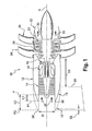
- the aircraft 140 represented in figure 1 is equipped with two motors 110 propellant propeller uncared, these engines being fixed by pylons 134 at the rear of the fuselage 141 of the aircraft, on both sides thereof.
- the nacelle 112 of each engine 110 comprises at its upstream end an air inlet 113 according to the invention which comprises an axial projection 142 for connection to the pylon 134.
- This pylon 134 extends substantially radially with respect to the axis A of the engine, from the projection 142 of the air intake to the outside to the fuselage 141 of the aircraft.
- the projection 142 of the air intake is located on the side of the fuselage 141 of the aircraft.
- the tower 134 is inclined at an angle ⁇ of between 5 and 45 °, for example about 20 °, with respect to a horizontal plane passing substantially at the end of the tower 134 connected to the fuselage 141.
- the projection 142 has a generally triangular or trapezoidal shape whose top or the small base is located upstream and whose (large) base is located downstream.
- the downstream base of the projection 142 extends angularly about the axis A at an angle less than or equal to about 180 °.
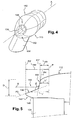
- This projection 142 forms the zone of the air inlet of greater axial length and its length, measured between the aforementioned plane P and a transverse plane P2 'passing at the upstream end of the projection, is denoted Lmax.
- This length Lmax is substantially equal to the length L2 of the air inlet 13 'of the figure 1 , this air intake 13 'having been lengthened to allow the integration of the pylon 34 to the engine.
- the length Lmax makes it possible to calculate the maximum value of the L / D ratio of the air inlet which is equal to Lmax / D and which is for example approximately 2.5.
- the projection 142 is connected to a substantially annular portion 144 of the air inlet which extends around the axis A, and which defines the zone of shorter length of the air inlet.
- This portion 144 is diametrically opposed to the projection 142.
- the length of this portion 144, measured between the plane P and a transverse plane P1 'passing at the downstream end of this portion, is denoted Lmin (the downstream end of the portion 144 being diametrically opposed to the upstream end of the projection 142).
- This length Lmin is substantially equal to the length L1 of the air inlet 13 of the figure 1 , that is to say the optimum minimum value of this air inlet, determined independently of the pylon.
- the length Lmin makes it possible to calculate the minimum value of the L / D ratio of the air inlet which is equal to Lmin / D and which is for example approximately 0.9.
- the leading edge 138 defines on either side of the axis A a dihedron having a relatively large opening angle ⁇ , that is to say greater than 90 °.
- This angle ⁇ is of the order of 120-150 ° in the example shown.
- the leading edge 138 of the air inlet thus defines on either side of the median plane a plurality of lengths L ', L "different from the air inlet, between Lmin and Lmax. allow to do vary the L / D ratio of the air inlet over its entire circumference. Unlike the prior art, the evolution of this ratio is not linear (where the leading edge extends in a single inclined plane of air inlet) but is instead non-linear and for example, approximately hyperbolic or parabolic. This particular configuration of the leading edge 138 makes it possible to define at least two air inlet planes.
- the leading edge 138 of the air inlet defines two intersecting planes P3, P4 inclined with respect to the axis A.
- the first upstream plane P3 is defined by the part of the leading edge of the projection 142 ( or the upstream sides of the aforementioned dihedra) and is inclined at an angle of between about 15 and 50 ° with respect to the axis A.
- the second downstream plane P4 is defined by the portion of the leading edge of the portion 144 of the air intake (or downstream sides of the dihedral) and is inclined at an angle of about 70-90 ° relative to the axis A.
- the zone 146 of junction between the air inlet 113 and the leading edge of the tower 134 is located in a transverse plane which extends between the transverse planes P1 'and P2'.
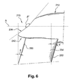
- the leading edge 238 of the air inlet 213 defines on either side of the axis A a dihedral having an opening angle ⁇ 'for example between 90 and 175 ° approximately. This angle ⁇ 'is about 170 ° in the example shown.
- the leading edge 250 of the pylon 234 is here inclined with respect to a plane perpendicular to the axis A of the motor, with an angle ⁇ of between 10 and 35 °, and preferably 20 °.
- the trailing edge 252 of the pylon 234 is also inclined with respect to a plane perpendicular to the axis A, of an angle ⁇ 'between 10 and 35 °, and preferably 20 °.
- the values of the angles ⁇ and ⁇ ' can be identical or different.
- the engine mounting pylon to the aircraft can also be inclined relative to a radial plane passing through the axis of the engine.
- the axial projection of the air inlet allows the integration of bulky equipment of the engine other than a pylon.
Landscapes
- Engineering & Computer Science (AREA)
- Aviation & Aerospace Engineering (AREA)
- Chemical & Material Sciences (AREA)
- Combustion & Propulsion (AREA)
- Physics & Mathematics (AREA)
- Geometry (AREA)
- Mechanical Engineering (AREA)
- General Engineering & Computer Science (AREA)
- Structures Of Non-Positive Displacement Pumps (AREA)
- Supercharger (AREA)
Abstract
Description
- La présente invention concerne une entrée d'air d'un moteur d'avion, et en particulier d'un moteur d'avion à hélices propulsives non carénées (en anglais « open-rotor pusher » ou « pusher unducted fan »).
- Un moteur de ce type (tel que celui décrit dans la demande
FR-A1-2 892 705 - Ce moteur est fixé à un avion par l'intermédiaire d'un pylône qui s'étend sensiblement radialement par rapport à l'axe longitudinal du moteur et dont l'extrémité radialement interne est reliée à l'extrémité amont de la nacelle du moteur, c'est-à-dire à l'entrée d'air de ce moteur.
- Le pylône doit être à une distance axiale suffisante des hélices et de l'extrémité amont ou bord d'attaque de l'entrée d'air, en particulier pour des raisons aérodynamiques. Dans la technique actuelle, il est nécessaire de rallonger l'entrée d'air du moteur en direction axiale pour permettre la liaison du pylône à l'entrée d'air et au moteur, ce qui entraîne une augmentation significative de la masse de la nacelle et de la traînée générée par celle-ci en fonctionnement.
- L'entrée d'air d'un moteur à hélices propulsives non carénées est généralement axisymétrique dans la technique actuelle, c'est-à-dire que son bord d'attaque est inscrit dans un plan perpendiculaire à l'axe du moteur. Une entrée d'air axisymétrique a un rapport UD constant sur sa circonférence, L étant la longueur locale de l'entrée d'air, mesurée parallèlement à l'axe du moteur entre un point du bord d'attaque et un plan passant au niveau de la roue d'entrée du moteur, et D étant le diamètre interne de l'entrée d'air, au niveau de cette roue d'entrée.
- Lorsque l'entrée d'air n'est pas axisymétrique, son bord d'attaque définit une surface approximativement plane appelée section de captation (en anglais « hilite » ou « high light »). On définit pour ce type d'entrée d'air une longueur globale d'entrée d'air qui est égale à la distance entre le plan transversal au niveau de la roue d'entrée du moteur et le point d'intersection entre le plan de captation de l'entrée d'air et l'axe moteur.
- On connaît par exemple des entrées d'air de moteur d'avion du type en biseau (en anglais « scarf ») dont le plan de captation a une inclinaison marquée par rapport à l'axe longitudinal du moteur, la partie inférieure de l'entrée d'air faisant saillie axialement vers l'amont par rapport à la partie supérieure de celle-ci. Une entrée d'air de ce type est définie par un rapport L/D « global » (longueur globale sur diamètre) et présente un rapport UD « local » (longueur locale sur diamètre) qui varie de façon linéaire sur la circonférence de l'entrée d'air.
- Cette forme particulière de l'entrée d'air en biseau a essentiellement pour fonction de limiter le bruit émis par le moteur vers l'amont, en direction du sol. En effet, la partie inférieure de plus grande longueur de l'entrée d'air en biseau permet de réfléchir et de dévier vers le haut une plus grande partie du bruit émis vers l'amont par le moteur en fonctionnement. Ce type de moteur est en général fixé sous l'aile d'un avion au moyen d'un pylône qui est reliée à l'entrée d'air au niveau de sa partie supérieure de plus petite longueur.
- L'invention a notamment pour but de proposer une solution simple, efficace et économique aux problèmes précités liés à l'intégration d'un pylône à l'entrée d'air d'un moteur d'avion à hélices propulsives non carénées.
- Elle propose à cet effet une entrée d'air d'un moteur d'avion du type à hélices propulsives non carénées, destinée à être reliée par un pylône au fuselage d'un avion, caractérisée en ce que la longueur locale de l'entrée d'air, mesurée parallèlement à l'axe du moteur entre un point du bord d'attaque de l'entrée d'air et un plan transversal situé au niveau d'une roue d'entrée du compresseur du moteur, est plus grande dans la zone de l'entrée d'air reliée au pylône et plus faible dans la zone de l'entrée d'air opposée au pylône.
- La longueur locale de l'entrée d'air selon l'invention varie sur la circonférence de l'entrée d'air, en étant maximale dans la zone reliée au pylône, et minimale dans la zone opposée, au contraire de la technique antérieure dans laquelle la partie supérieure de plus faible longueur de l'entrée d'air en biseau est reliée au pylône d'accrochage. La forme et les dimensions de la zone de l'entrée d'air reliée au pylône sont optimisées en fonction du dimensionnement du pylône, alors que la forme et les dimensions du reste de l'entrée d'air sont optimisées indépendamment de ce pylône, de façon à limiter la masse de l'entrée d'air et la traînée générée par la nacelle du moteur en fonctionnement.
- La variation de la longueur locale de l'entrée d'air est non linéaire sur la circonférence de l'entrée d'air. Contrairement à la technique antérieure, la section de captation de l'entrée d'air n'est pas plane et il n'est pas possible de définir la longueur de l'entrée d'air selon l'invention par un rapport UD « global ».
- Le rapport L/D « local » de l'entrée d'air selon l'invention varie de préférence entre 2,5 et 0,9 environ entre la zone reliée au pylône et la zone opposée de l'entrée d'air, L étant la longueur locale de l'entrée d'air, et D étant son diamètre interne, L et D étant mesurés comme indiqué ci-dessus.
- Avantageusement, dans une direction perpendiculaire à un plan médian passant par l'axe du pylône et par l'axe du moteur, le bord d'attaque de l'entrée d'air a un contour sensiblement en forme de dièdre. L'angle au sommet du dièdre est par exemple compris entre 90 et 175° environ. Le sommet du dièdre peut avoir une forme arrondie concave du côté de l'ouverture du dièdre. Les côtés du dièdre peuvent être sensiblement rectilignes ou incurvés concaves ou convexes.
- De préférence, l'entrée d'air est symétrique par rapport à un plan médian passant par l'axe du pylône et par l'axe du moteur. Le bord d'attaque de l'entrée d'air selon l'invention définit alors deux dièdres situés de part et d'autre de ce plan médian et reliés par des arrondis.
- Les côtés amont de ces deux dièdres s'étendent dans un premier plan d'entrée d'air qui est incliné par rapport à l'axe du moteur, et les côtés aval des dièdres s'étendent dans un second plan d'entrée d'air plus incliné sur l'axe du moteur. Ces deux plans sont sécants, la ligne de coupe de ces deux plans passant sensiblement au niveau des sommets des dièdres. L'entrée d'air selon l'invention est donc définie par deux plans d'entrée d'air contre un seul dans la technique antérieure.
- Selon un autre aspect de l'invention, l'entrée d'air comprend une saillie axiale, le pylône étant destiné à s'étendre sensiblement axialement et radialement par rapport à l'axe du moteur, depuis cette saillie de l'entrée d'air. La forme et les dimensions de cette saillie sont déterminées en fonction de celles du pylône. Cette saillie peut également servir à l'installation d'autres équipements encombrants du moteur.
- Le bord d'attaque et/ou le bord de fuite du pylône peuvent être inclinés d'un angle compris entre 10 et 35° environ, par rapport à un plan transversal.
- L'invention concerne également un moteur d'avion à hélices propulsives non carénées, comprenant une entrée d'air telle que décrite ci-dessus.
- L'invention concerne enfin un avion, caractérisé en ce qu'il comprend deux moteurs ou plus du type précité, ces moteurs étant fixés par des pylônes sur l'arrière du fuselage de l'avion, de part et d'autre de celui-ci. Lorsque l'avion comporte deux moteurs, le pylône de fixation de chaque moteur est de préférence incliné d'un angle compris entre 5 et 45°, et par exemple de 20° environ, par rapport à un plan horizontal passant sensiblement au niveau de l'extrémité du pylône reliée au fuselage. Lorsque l'avion comporte un moteur supplémentaire, le pylône de fixation de ce moteur peut être dans un plan sensiblement vertical. Ce troisième moteur peut être situé au-dessus du fuselage de l'avion.
- L'invention sera mieux comprise et d'autres détails, caractéristiques et avantages de la présente invention apparaîtront plus clairement à la lecture de la description qui suit faite à titre d'exemple non limitatif et en référence aux dessins annexés dans lesquels :
- la
figure 1 est une vue schématique en coupe axiale d'un moteur à hélices propulsives non carénées, - la
figure 2 est une vue schématique en perspective d'un avion équipé de deux moteurs à hélices propulsives non carénées selon l'invention, - la
figure 3 est une vue à plus grande échelle d'un des moteurs de lafigure 2 , - la
figure 4 est une vue schématique en perspective de la nacelle et du pylône du moteur de lafigure 3 , et - la
figure 5 est une vue schématique partielle de côté de la nacelle et du pylône de lafigure 4 , à plus grande échelle. - On se réfère d'abord à la
figure 1 qui représente un moteur d'avion 10 à hélices propulsives non carénées, ce moteur 10 comportant une turbomachine entourée par une nacelle 12 sensiblement axisymétrique dont l'extrémité amont forme une entrée d'air 13. - La turbomachine comprend d'amont en aval, dans le sens d'écoulement des gaz à l'intérieur de celle-ci, un compresseur 14, une chambre de combustion 16, une turbine amont 18 haute-pression, et deux turbines aval 20, 22 basse-pression contrarotatives, c'est-à-dire tournant dans des sens opposés autour de l'axe longitudinal A du moteur.
- Chaque turbine aval 20, 22 est solidaire en rotation d'une hélice externe 24, 26 qui s'étend sensiblement radialement à l'extérieur de la nacelle 12.
- Le flux d'air 28 qui pénètre dans l'entrée d'air 13 passe dans le compresseur 14 pour y être comprimé, puis est mélangé à du carburant et brûlé dans la chambre de combustion 16, les gaz de combustion étant alors injectés dans les turbines pour entraîner en rotation les hélices 26, 28 qui fournissent la majeure partie de la poussée du moteur. Les gaz de combustion 30 qui sortent des turbines 20, 22 sont ensuite éjectés à travers une tuyère aval 32 pour augmenter la poussée du moteur.
- Les hélices 24, 26 sont situées au voisinage de l'extrémité aval du moteur et sont dites propulsives ou de propulsion, par opposition à des hélices externes qui seraient situées à l'amont du moteur qui seraient dites de traction.
- Ce type de moteur est relié à une partie d'un avion, telle que son fuselage, par l'intermédiaire d'un pylône 34 qui s'étend sensiblement radialement par rapport à l'axe A, à l'extérieur de la nacelle 12, et qui doit être à une distance axiale X1 suffisante des bords d'attaque des aubes de l'hélice amont 24 et une distance axiale X2 suffisante du bord d'attaque 38 de l'entrée d'air, notamment pour des raisons aérodynamiques. Il est alors nécessaire dans la technique actuelle de rallonger axialement l'entrée d'air 13 pour permettre l'intégration du pylône 34 au moteur.
- Dans l'exemple de la
figure 1 , l'entrée d'air 13 représentée en traits continus a une longueur minimale optimale pour assurer notamment la canalisation de l'air jusqu'au compresseur 16, tandis que l'entrée d'air 13' représentée en traits discontinus a été allongée pour autoriser l'intégration du pylône 34 au moteur 10. L'allongement de l'entrée d'air augmente toutefois de manière importante la masse du moteur et la traînée générée par celle-ci en vol. - L'entrée d'air 13 du moteur est profilée et son extrémité amont ou bord 38 d'attaque des gaz a en section une forme arrondie convexe.
- Une entrée d'air d'un moteur d'avion peut notamment être définie par un rapport L/D « local » qui dans l'exemple représenté est constant sur toute la circonférence de l'entrée d'air. D est le diamètre interne de l'entrée d'air 13, mesuré au niveau de la première roue ou roue d'entrée du compresseur 14, et L est la longueur locale de cette entrée d'air mesurée parallèlement à l'axe A entre un point du bord d'attaque 38 et un plan transversal P situé au niveau de la roue d'entrée du compresseur 14. L'entrée d'air 13 est ici axisymétrique et tous les points du bord d'attaque 38 sont situés dans un même plan transversal P1 (ou P2 dans le cas de l'entrée d'air 13'), appelé plan ou section de captation.
- L'entrée d'air 13 en traits continus a une longueur L1 (mesurée entre P et P1) et est définie par le rapport L1/D, et l'entrée d'air 13' en traits discontinus a une longueur L2 (mesurée entre P et P2) et est définie par le rapport L2/D.
- L'invention permet de remédier aux problèmes précités liés au rallongement de l'entrée d'air du moteur grâce à une entrée d'air dont le rapport L/D n'est pas constant mais varie de façon non linéaire sur la circonférence de l'entrée d'air, la zone de l'entrée d'air de plus grande longueur étant reliée au pylône.
- Les
figures 2 à 5 représentent un mode préféré de réalisation de l'invention, dans lequel les éléments déjà décrits en référence à lafigure 1 sont référencés par les mêmes chiffres, augmentés d'une centaine. - L'avion 140 représenté en
figure 1 est équipé de deux moteurs 110 à hélices propulsives non carénées, ces moteurs étant fixés par des pylônes 134 à l'arrière du fuselage 141 de l'avion, de part et d'autre de celui-ci. - La nacelle 112 de chaque moteur 110 comprend à son extrémité amont une entrée d'air 113 selon l'invention qui comprend une saillie axiale 142 de liaison au pylône 134. Ce pylône 134 s'étend sensiblement radialement par rapport à l'axe A du moteur, depuis la saillie 142 de l'entrée d'air vers l'extérieur jusqu'au fuselage 141 de l'avion. La saillie 142 de l'entrée d'air est donc située du côté du fuselage 141 de l'avion. Le pylône 134 est incliné d'un angle α compris entre 5 et 45°, et par exemple de 20° environ, par rapport à un plan horizontal passant sensiblement au niveau de l'extrémité du pylône 134 reliée au fuselage 141.
- La saillie 142 a une forme générale triangulaire ou trapézoïdale dont le sommet ou la petite base est situé à l'amont et dont la (grande) base est située à l'aval. La base aval de la saillie 142 s'étend angulairement autour de l'axe A sur un angle inférieur ou égal à 180° environ.
- Cette saillie 142 forme la zone de l'entrée d'air de plus grande longueur axiale et sa longueur, mesurée entre le plan P précité et un plan transversal P2' passant au niveau de l'extrémité amont de la saillie, est notée Lmax. Cette longueur Lmax est sensiblement égale à la longueur L2 de l'entrée d'air 13' de la
figure 1 , cette entrée d'air 13' ayant été rallongée pour autoriser l'intégration du pylône 34 au moteur. - La longueur Lmax permet de calculer la valeur maximale du rapport L/D de l'entrée d'air qui est égale à Lmax/D et qui vaut par exemple 2,5 environ.
- La saillie 142 est reliée à une portion sensiblement annulaire 144 de l'entrée d'air qui s'étend autour de l'axe A, et qui définit la zone de plus faible longueur de l'entrée d'air. Cette portion 144 est diamétralement opposée à la saillie 142. La longueur de cette portion 144, mesurée entre le plan P et un plan transversal P1' passant au niveau de l'extrémité aval de cette portion, est notée Lmin (l'extrémité aval de la portion 144 étant diamétralement opposée à l'extrémité amont de la saillie 142). Cette longueur Lmin est sensiblement égale à la longueur L1 de l'entrée d'air 13 de la
figure 1 , c'est-à-dire à la valeur minimale optimale de cette entrée d'air, déterminée indépendamment du pylône. - La longueur Lmin permet de calculer la valeur minimale du rapport L/D de l'entrée d'air qui est égale à Lmin/D et qui vaut par exemple 0,9 environ.
- Lorsque l'entrée d'air 113 est vue de côté ou dans une direction perpendiculaire au plan médian passant par l'axe A du moteur et l'axe du pylône 134, comme c'est le cas en
figure 5 , le bord d'attaque 138 définit de part et d'autre de l'axe A un dièdre ayant un angle d'ouverture β relativement grand, c'est-à-dire supérieur à 90°. Cet angle β est de l'ordre de 120-150° dans l'exemple représenté. - Le bord d'attaque 138 de l'entrée d'air définit ainsi de part et d'autre du plan médian une pluralité de longueurs L', L" différentes de l'entrée d'air, comprises entre Lmin et Lmax. Ces longueurs permettent de faire varier le rapport L/D de l'entrée d'air sur toute sa circonférence. Au contraire de la technique antérieure, l'évolution de ce rapport n'est pas linéaire (cas où le bord d'attaque s'étend dans un seul et même plan incliné d'entrée d'air) mais est au contraire non linéaire et par exemple approximativement hyperbolique ou parabolique. Cette configuration particulière du bord d'attaque 138 permet de définir au moins deux plans d'entrée d'air.
- Dans l'exemple de la
figure 5 , le bord d'attaque 138 de l'entrée d'air définit deux plans P3, P4 sécants inclinés par rapport à l'axe A. Le premier plan amont P3 est défini par la partie du bord d'attaque de la saillie 142 (ou les côtés amont des dièdres précités) et est incliné d'un angle compris entre 15 et 50° environ par rapport à l'axe A. Le second plan aval P4 est défini par la partie du bord d'attaque de la portion 144 de l'entrée d'air (ou des côtés aval des dièdres) et est incliné d'un angle de 70-90° environ par rapport à l'axe A. Ces deux plans P3, P4 se coupent sensiblement au niveau des zones de jonction entre la saillie 142 et la portion annulaire 144 de l'entrée d'air. - Comme cela est également visible en
figure 5 , la zone 146 de jonction entre l'entrée d'air 113 et le bord d'attaque du pylône 134 est située dans un plan transversal qui s'étend entre les plans transversaux P1' et P2'. - Dans la variante représentée en
figure 6 , le bord d'attaque 238 de l'entrée d'air 213 définit de part et d'autre de l'axe A un dièdre ayant un angle d'ouverture β' par exemple compris entre 90 et 175° environ. Cet angle β' est de 170° environ dans l'exemple représenté. - Le bord d'attaque 250 du pylône 234 est ici incliné par rapport à un plan perpendiculaire à l'axe A du moteur, d'un angle γ compris entre 10 et 35° environ, et de préférence de 20°. Le bord de fuite 252 du pylône 234 est également incliné par rapport à un plan perpendiculaire à l'axe A, d'un angle γ' compris entre 10 et 35° environ, et de préférence de 20°. Les valeurs des angles γ et γ' peuvent être identiques ou différentes.
- Le pylône de fixation du moteur à l'avion peut en outre être incliné par rapport à un plan radial passant par l'axe du moteur.
- Dans une variante de réalisation de l'invention, la saillie axiale de l'entrée d'air permet l'intégration d'un équipement encombrant du moteur autre qu'un pylône.
Claims (11)
- Entrée d'air (113) d'un moteur d'avion du type à hélices propulsives non carénées, destinée à être reliée par un pylône (134) au fuselage (141) d'un avion, caractérisée en ce que la longueur locale de l'entrée d'air, mesurée parallèlement à l'axe (A) du moteur entre un point du bord d'attaque (138) de l'entrée d'air et un plan transversal (P) situé au niveau d'une roue d'entrée du compresseur du moteur, est plus grande dans la zone (142) de l'entrée d'air reliée au pylône et plus faible dans la zone de l'entrée d'air opposée au pylône.
- Entrée d'air selon la revendication 1, caractérisée en ce que le rapport L/D varie entre 2,5 et 0,9 environ entre la zone (142) de l'entrée d'air reliée au pylône (134) et la zone opposée de l'entré d'air, L étant la longueur locale de l'entrée d'air, et D étant son diamètre interne mesuré au niveau de la roue d'entrée du compresseur du moteur.
- Entrée d'air selon la revendication 1 ou 2, caractérisée en ce que, dans une direction perpendiculaire à un plan médian passant par l'axe du pylône (134) et par l'axe (A) du moteur, le bord d'attaque (138) de l'entrée d'air a un contour sensiblement en forme de dièdre.
- Entrée d'air selon la revendication 3, caractérisée en ce que l'angle (β,β') au sommet du dièdre est compris entre 90 et 175°.
- Entrée d'air selon la revendication 3 ou 4, caractérisée en ce que le sommet du dièdre a une forme arrondie concave du côté de l'ouverture du dièdre.
- Entrée d'air selon l'une des revendications précédentes, caractérisée en ce qu'elle comprend une saillie axiale (142) vers l'amont, le pylône (134) étant destinée à s'étendre sensiblement radialement par rapport à l'axe (A) du moteur depuis cette saillie.
- Entrée d'air selon l'une des revendications précédentes, caractérisée en ce qu'elle est symétrique par rapport à un plan médian passant par l'axe du pylône (134) et par l'axe (A) du moteur.
- Entrée d'air selon l'une des revendications précédentes, caractérisée en ce que le bord d'attaque (250) et/ou le bord de fuite (252) du pylône (234) sont inclinés d'un angle (γ) compris entre 10 et 35° environ, par rapport à un plan transversal.
- Moteur d'avion (110) à hélices propulsives non carénées, caractérisé en ce qu'il comprend une entrée d'air (113) selon l'une des revendications précédentes.
- Avion (140), caractérisé en ce qu'il comprend au moins deux moteurs selon la revendication 9, ces deux moteurs (110) étant fixés par des pylônes (134) sur l'arrière du fuselage (141) de l'avion, de part et d'autre de celui-ci.
- Avion selon la revendication 10, caractérisé en ce qu'il comprend un troisième moteur fixé par un pylône sur l'arrière du fuselage de l'avion, ce pylône s'étendant sensiblement verticalement au-dessus du fuselage.
Applications Claiming Priority (2)
| Application Number | Priority Date | Filing Date | Title |
|---|---|---|---|
| FR0806381A FR2938504B1 (fr) | 2008-11-14 | 2008-11-14 | Entree d'air d'un moteur d'avion a helices propulsives non carenees |
| PCT/FR2009/001295 WO2010055224A1 (fr) | 2008-11-14 | 2009-11-09 | Entrée d'air d'un moteur d'avion à hélices propulsives non carénées |
Publications (2)
| Publication Number | Publication Date |
|---|---|
| EP2344381A1 EP2344381A1 (fr) | 2011-07-20 |
| EP2344381B1 true EP2344381B1 (fr) | 2012-08-01 |
Family
ID=40678051
Family Applications (1)
| Application Number | Title | Priority Date | Filing Date |
|---|---|---|---|
| EP20090760929 Active EP2344381B1 (fr) | 2008-11-14 | 2009-11-09 | Entree d'air d'un moteur d'avion a helices propulsives non carenees |
Country Status (10)
| Country | Link |
|---|---|
| US (1) | US8622340B2 (fr) |
| EP (1) | EP2344381B1 (fr) |
| JP (1) | JP5416786B2 (fr) |
| CN (1) | CN102216158B (fr) |
| BR (1) | BRPI0921378B1 (fr) |
| CA (1) | CA2743009C (fr) |
| ES (1) | ES2393069T3 (fr) |
| FR (1) | FR2938504B1 (fr) |
| RU (1) | RU2507126C2 (fr) |
| WO (1) | WO2010055224A1 (fr) |
Families Citing this family (10)
| Publication number | Priority date | Publication date | Assignee | Title |
|---|---|---|---|---|
| GB201102987D0 (en) | 2011-02-22 | 2011-04-06 | Rolls Royce Plc | A propfan engine |
| EP4375496A2 (fr) * | 2012-10-23 | 2024-05-29 | General Electric Company | Ensemble d'aubes directrices pour un système de production de poussée non caréné |
| US9932933B2 (en) | 2012-12-20 | 2018-04-03 | United Technologies Corporation | Low pressure ratio fan engine having a dimensional relationship between inlet and fan size |
| US9920653B2 (en) | 2012-12-20 | 2018-03-20 | United Technologies Corporation | Low pressure ratio fan engine having a dimensional relationship between inlet and fan size |
| US11480104B2 (en) * | 2013-03-04 | 2022-10-25 | Raytheon Technologies Corporation | Gas turbine engine inlet |
| FR3050721B1 (fr) * | 2016-04-28 | 2018-04-13 | Airbus Operations | Ensemble moteur pour aeronef comprenant un bord d'attaque de mat integre a une rangee annulaire d'aubes directrices de sortie non carenees |
| FR3068735B1 (fr) * | 2017-07-06 | 2019-07-26 | Safran Aircraft Engines | Turboreacteur a faible bruit de soufflante |
| GB201809822D0 (en) | 2018-06-15 | 2018-08-01 | Rolls Royce Plc | Gas turbine engine |
| GB202001971D0 (en) | 2020-02-13 | 2020-04-01 | Rolls Royce Plc | Nacelle for gas turbine engine and aircraft comprising the same |
| RU203051U1 (ru) * | 2020-10-23 | 2021-03-19 | Михаил Николаевич Киселёв | Устройство создания тяги от встречного потока текучей среды |
Family Cites Families (17)
| Publication number | Priority date | Publication date | Assignee | Title |
|---|---|---|---|---|
| US3765623A (en) * | 1971-10-04 | 1973-10-16 | Mc Donnell Douglas Corp | Air inlet |
| JPS5410259B2 (fr) * | 1973-03-30 | 1979-05-02 | ||
| US3946830A (en) * | 1974-09-06 | 1976-03-30 | General Electric Company | Inlet noise deflector |
| US5156353A (en) * | 1987-04-13 | 1992-10-20 | General Electric Company | Aircraft pylon |
| US4966338A (en) * | 1987-08-05 | 1990-10-30 | General Electric Company | Aircraft pylon |
| US4976396A (en) * | 1987-11-13 | 1990-12-11 | The Boeing Company | Aircraft configuration with aft mounted engines |
| US4953812A (en) * | 1987-11-13 | 1990-09-04 | The Boeing Company | Aircraft configuration with aft mounted engines and method |
| US4927329A (en) * | 1988-10-21 | 1990-05-22 | General Electric Company | Aircraft engine unducted fan blade pitch control system |
| US5209428A (en) * | 1990-05-07 | 1993-05-11 | Lockheed Corporation | Propulsion system for a vertical and short takeoff and landing aircraft |
| JPH07179199A (ja) * | 1992-08-27 | 1995-07-18 | General Electric Co <Ge> | 円弧輪郭を有する航空機エンジンナセル |
| GB9424495D0 (en) * | 1994-12-05 | 1995-01-25 | Short Brothers Plc | Aerodynamic low drag structure |
| US5915403A (en) * | 1998-04-14 | 1999-06-29 | The Boeing Company | Biplanar scarfed nacelle inlet |
| US6129309A (en) * | 1998-07-24 | 2000-10-10 | Mcdonnell Douglas Corporation | Aircraft engine apparatus with reduced inlet vortex |
| GB2385382B (en) * | 2002-02-13 | 2006-02-15 | Rolls Royce Plc | A cowl structure for a gas turbine engine |
| FR2892705B1 (fr) * | 2005-11-03 | 2009-04-24 | Airbus France Sas | Aeronef a impact environnemental reduit. |
| FR2896771B1 (fr) * | 2006-01-27 | 2008-04-25 | Snecma Sa | Entree d'air de turboreacteur a double flux |
| FR2898583B1 (fr) * | 2006-03-20 | 2008-04-18 | Airbus France Sas | Aeronef a impact environnemental reduit |
-
2008
- 2008-11-14 FR FR0806381A patent/FR2938504B1/fr not_active Expired - Fee Related
-
2009
- 2009-11-09 CN CN2009801457505A patent/CN102216158B/zh active Active
- 2009-11-09 ES ES09760929T patent/ES2393069T3/es active Active
- 2009-11-09 US US13/128,259 patent/US8622340B2/en active Active
- 2009-11-09 RU RU2011123883/11A patent/RU2507126C2/ru active
- 2009-11-09 WO PCT/FR2009/001295 patent/WO2010055224A1/fr active Application Filing
- 2009-11-09 BR BRPI0921378-3A patent/BRPI0921378B1/pt active IP Right Grant
- 2009-11-09 EP EP20090760929 patent/EP2344381B1/fr active Active
- 2009-11-09 CA CA2743009A patent/CA2743009C/fr active Active
- 2009-11-09 JP JP2011543789A patent/JP5416786B2/ja active Active
Also Published As
| Publication number | Publication date |
|---|---|
| BRPI0921378B1 (pt) | 2020-03-31 |
| CN102216158B (zh) | 2013-12-11 |
| US20110220217A1 (en) | 2011-09-15 |
| BRPI0921378A2 (pt) | 2015-12-29 |
| CA2743009A1 (fr) | 2010-05-20 |
| RU2507126C2 (ru) | 2014-02-20 |
| EP2344381A1 (fr) | 2011-07-20 |
| RU2011123883A (ru) | 2012-12-20 |
| CA2743009C (fr) | 2017-03-14 |
| JP5416786B2 (ja) | 2014-02-12 |
| JP2012508668A (ja) | 2012-04-12 |
| CN102216158A (zh) | 2011-10-12 |
| US8622340B2 (en) | 2014-01-07 |
| WO2010055224A1 (fr) | 2010-05-20 |
| FR2938504A1 (fr) | 2010-05-21 |
| FR2938504B1 (fr) | 2010-12-10 |
| ES2393069T3 (es) | 2012-12-18 |
Similar Documents
| Publication | Publication Date | Title |
|---|---|---|
| EP2344381B1 (fr) | Entree d'air d'un moteur d'avion a helices propulsives non carenees | |
| EP3325346B1 (fr) | Aeronef comprenant un propulseur arriere carene avec stator d'entree a volets mobiles | |
| EP2928769B1 (fr) | Pale d'helice pour turbomachine | |
| EP2760737B1 (fr) | Pale pour une helice de turbomachine, notamment a soufflante non carenee, helice et turbomachine correspondantes | |
| FR3027053A1 (fr) | Stator de turbomachine d'aeronef | |
| WO2019043330A1 (fr) | Aube de redresseur de soufflante de turbomachine, ensemble de turbomachine comprenant une telle aube et turbomachine equipee de ladite aube ou dudit ensemble | |
| WO2016132073A1 (fr) | Ensemble propulsif pour aeronef comprenant un turboreacteur a soufflante non carenee et un pylone d'accrochage | |
| FR2995282A1 (fr) | Pylone de montage d'un moteur a la structure d'un aeronef | |
| FR3032941A1 (fr) | Soufflante non carenee de turbomachine d'aeronef | |
| FR2982842A1 (fr) | Avion | |
| WO2023170357A1 (fr) | Ensemble propulsif pour un aeronef | |
| FR3133367A1 (fr) | Propulseur aeronautique | |
| CA2507168C (fr) | Nacelle de reacteur pour avion supersonique | |
| FR2965250A1 (fr) | Installation de moteurs a l'arriere du fuselage d'un aeronef, et aeronef pourvu d'une telle installation. | |
| FR2935348A1 (fr) | Turbomachine a helices non carenees | |
| FR2998330A1 (fr) | Moyeu de carter pour turbomachine d'aeronef comprenant une piece de fonderie compacte a deflecteur integre au flasque aval | |
| FR3082229A1 (fr) | Turbomachine avec une aube partielle de compression | |
| FR3101614A1 (fr) | Système propulsif pour aéronef à turbomoteur déporté | |
| WO2024033065A1 (fr) | Aube à calage variable de stator de turbomachine d'aéronef et turbomachine d'aéronef | |
| WO2023110701A1 (fr) | Turbomachine non carénée comprenant des aubes de stator présentant des cordes différentes | |
| WO2017109430A1 (fr) | Turbomachine à hélice à clipping inversé | |
| EP4367023A1 (fr) | Propulseur aeronautique | |
| FR3125089A1 (fr) | Propulseur aeronautique | |
| FR3050759A1 (fr) | Ensemble de redressement de flux d'air et turbomachine comprenant un tel ensemble | |
| WO2023281192A1 (fr) | Propulseur aeronautique |
Legal Events
| Date | Code | Title | Description |
|---|---|---|---|
| PUAI | Public reference made under article 153(3) epc to a published international application that has entered the european phase |
Free format text: ORIGINAL CODE: 0009012 |
|
| 17P | Request for examination filed |
Effective date: 20110502 |
|
| AK | Designated contracting states |
Kind code of ref document: A1 Designated state(s): AT BE BG CH CY CZ DE DK EE ES FI FR GB GR HR HU IE IS IT LI LT LU LV MC MK MT NL NO PL PT RO SE SI SK SM TR |
|
| AX | Request for extension of the european patent |
Extension state: AL BA RS |
|
| DAX | Request for extension of the european patent (deleted) | ||
| GRAP | Despatch of communication of intention to grant a patent |
Free format text: ORIGINAL CODE: EPIDOSNIGR1 |
|
| GRAS | Grant fee paid |
Free format text: ORIGINAL CODE: EPIDOSNIGR3 |
|
| GRAA | (expected) grant |
Free format text: ORIGINAL CODE: 0009210 |
|
| AK | Designated contracting states |
Kind code of ref document: B1 Designated state(s): AT BE BG CH CY CZ DE DK EE ES FI FR GB GR HR HU IE IS IT LI LT LU LV MC MK MT NL NO PL PT RO SE SI SK SM TR |
|
| REG | Reference to a national code |
Ref country code: GB Ref legal event code: FG4D Free format text: NOT ENGLISH |
|
| REG | Reference to a national code |
Ref country code: CH Ref legal event code: EP Ref country code: AT Ref legal event code: REF Ref document number: 568518 Country of ref document: AT Kind code of ref document: T Effective date: 20120815 |
|
| REG | Reference to a national code |
Ref country code: IE Ref legal event code: FG4D Free format text: LANGUAGE OF EP DOCUMENT: FRENCH |
|
| REG | Reference to a national code |
Ref country code: DE Ref legal event code: R096 Ref document number: 602009008727 Country of ref document: DE Effective date: 20120927 |
|
| REG | Reference to a national code |
Ref country code: SE Ref legal event code: TRGR |
|
| REG | Reference to a national code |
Ref country code: NL Ref legal event code: VDEP Effective date: 20120801 |
|
| REG | Reference to a national code |
Ref country code: AT Ref legal event code: MK05 Ref document number: 568518 Country of ref document: AT Kind code of ref document: T Effective date: 20120801 |
|
| REG | Reference to a national code |
Ref country code: ES Ref legal event code: FG2A Ref document number: 2393069 Country of ref document: ES Kind code of ref document: T3 Effective date: 20121218 |
|
| REG | Reference to a national code |
Ref country code: LT Ref legal event code: MG4D Effective date: 20120801 |
|
| PG25 | Lapsed in a contracting state [announced via postgrant information from national office to epo] |
Ref country code: CY Free format text: LAPSE BECAUSE OF FAILURE TO SUBMIT A TRANSLATION OF THE DESCRIPTION OR TO PAY THE FEE WITHIN THE PRESCRIBED TIME-LIMIT Effective date: 20120801 Ref country code: LT Free format text: LAPSE BECAUSE OF FAILURE TO SUBMIT A TRANSLATION OF THE DESCRIPTION OR TO PAY THE FEE WITHIN THE PRESCRIBED TIME-LIMIT Effective date: 20120801 Ref country code: IS Free format text: LAPSE BECAUSE OF FAILURE TO SUBMIT A TRANSLATION OF THE DESCRIPTION OR TO PAY THE FEE WITHIN THE PRESCRIBED TIME-LIMIT Effective date: 20121201 Ref country code: AT Free format text: LAPSE BECAUSE OF FAILURE TO SUBMIT A TRANSLATION OF THE DESCRIPTION OR TO PAY THE FEE WITHIN THE PRESCRIBED TIME-LIMIT Effective date: 20120801 Ref country code: FI Free format text: LAPSE BECAUSE OF FAILURE TO SUBMIT A TRANSLATION OF THE DESCRIPTION OR TO PAY THE FEE WITHIN THE PRESCRIBED TIME-LIMIT Effective date: 20120801 Ref country code: HR Free format text: LAPSE BECAUSE OF FAILURE TO SUBMIT A TRANSLATION OF THE DESCRIPTION OR TO PAY THE FEE WITHIN THE PRESCRIBED TIME-LIMIT Effective date: 20120801 Ref country code: NO Free format text: LAPSE BECAUSE OF FAILURE TO SUBMIT A TRANSLATION OF THE DESCRIPTION OR TO PAY THE FEE WITHIN THE PRESCRIBED TIME-LIMIT Effective date: 20121101 |
|
| PG25 | Lapsed in a contracting state [announced via postgrant information from national office to epo] |
Ref country code: PL Free format text: LAPSE BECAUSE OF FAILURE TO SUBMIT A TRANSLATION OF THE DESCRIPTION OR TO PAY THE FEE WITHIN THE PRESCRIBED TIME-LIMIT Effective date: 20120801 Ref country code: LV Free format text: LAPSE BECAUSE OF FAILURE TO SUBMIT A TRANSLATION OF THE DESCRIPTION OR TO PAY THE FEE WITHIN THE PRESCRIBED TIME-LIMIT Effective date: 20120801 Ref country code: PT Free format text: LAPSE BECAUSE OF FAILURE TO SUBMIT A TRANSLATION OF THE DESCRIPTION OR TO PAY THE FEE WITHIN THE PRESCRIBED TIME-LIMIT Effective date: 20121203 Ref country code: SI Free format text: LAPSE BECAUSE OF FAILURE TO SUBMIT A TRANSLATION OF THE DESCRIPTION OR TO PAY THE FEE WITHIN THE PRESCRIBED TIME-LIMIT Effective date: 20120801 Ref country code: GR Free format text: LAPSE BECAUSE OF FAILURE TO SUBMIT A TRANSLATION OF THE DESCRIPTION OR TO PAY THE FEE WITHIN THE PRESCRIBED TIME-LIMIT Effective date: 20121102 |
|
| PGFP | Annual fee paid to national office [announced via postgrant information from national office to epo] |
Ref country code: ES Payment date: 20121114 Year of fee payment: 4 |
|
| PG25 | Lapsed in a contracting state [announced via postgrant information from national office to epo] |
Ref country code: NL Free format text: LAPSE BECAUSE OF FAILURE TO SUBMIT A TRANSLATION OF THE DESCRIPTION OR TO PAY THE FEE WITHIN THE PRESCRIBED TIME-LIMIT Effective date: 20120801 |
|
| PG25 | Lapsed in a contracting state [announced via postgrant information from national office to epo] |
Ref country code: CZ Free format text: LAPSE BECAUSE OF FAILURE TO SUBMIT A TRANSLATION OF THE DESCRIPTION OR TO PAY THE FEE WITHIN THE PRESCRIBED TIME-LIMIT Effective date: 20120801 Ref country code: EE Free format text: LAPSE BECAUSE OF FAILURE TO SUBMIT A TRANSLATION OF THE DESCRIPTION OR TO PAY THE FEE WITHIN THE PRESCRIBED TIME-LIMIT Effective date: 20120801 Ref country code: RO Free format text: LAPSE BECAUSE OF FAILURE TO SUBMIT A TRANSLATION OF THE DESCRIPTION OR TO PAY THE FEE WITHIN THE PRESCRIBED TIME-LIMIT Effective date: 20120801 Ref country code: DK Free format text: LAPSE BECAUSE OF FAILURE TO SUBMIT A TRANSLATION OF THE DESCRIPTION OR TO PAY THE FEE WITHIN THE PRESCRIBED TIME-LIMIT Effective date: 20120801 |
|
| BERE | Be: lapsed |
Owner name: SNECMA Effective date: 20121130 |
|
| PG25 | Lapsed in a contracting state [announced via postgrant information from national office to epo] |
Ref country code: SK Free format text: LAPSE BECAUSE OF FAILURE TO SUBMIT A TRANSLATION OF THE DESCRIPTION OR TO PAY THE FEE WITHIN THE PRESCRIBED TIME-LIMIT Effective date: 20120801 |
|
| PLBE | No opposition filed within time limit |
Free format text: ORIGINAL CODE: 0009261 |
|
| STAA | Information on the status of an ep patent application or granted ep patent |
Free format text: STATUS: NO OPPOSITION FILED WITHIN TIME LIMIT |
|
| 26N | No opposition filed |
Effective date: 20130503 |
|
| PG25 | Lapsed in a contracting state [announced via postgrant information from national office to epo] |
Ref country code: BG Free format text: LAPSE BECAUSE OF FAILURE TO SUBMIT A TRANSLATION OF THE DESCRIPTION OR TO PAY THE FEE WITHIN THE PRESCRIBED TIME-LIMIT Effective date: 20121101 |
|
| REG | Reference to a national code |
Ref country code: IE Ref legal event code: MM4A |
|
| REG | Reference to a national code |
Ref country code: DE Ref legal event code: R097 Ref document number: 602009008727 Country of ref document: DE Effective date: 20130503 |
|
| PG25 | Lapsed in a contracting state [announced via postgrant information from national office to epo] |
Ref country code: BE Free format text: LAPSE BECAUSE OF NON-PAYMENT OF DUE FEES Effective date: 20121130 |
|
| PG25 | Lapsed in a contracting state [announced via postgrant information from national office to epo] |
Ref country code: IE Free format text: LAPSE BECAUSE OF NON-PAYMENT OF DUE FEES Effective date: 20121109 |
|
| PG25 | Lapsed in a contracting state [announced via postgrant information from national office to epo] |
Ref country code: MT Free format text: LAPSE BECAUSE OF FAILURE TO SUBMIT A TRANSLATION OF THE DESCRIPTION OR TO PAY THE FEE WITHIN THE PRESCRIBED TIME-LIMIT Effective date: 20120801 |
|
| PG25 | Lapsed in a contracting state [announced via postgrant information from national office to epo] |
Ref country code: MC Free format text: LAPSE BECAUSE OF NON-PAYMENT OF DUE FEES Effective date: 20121130 Ref country code: TR Free format text: LAPSE BECAUSE OF FAILURE TO SUBMIT A TRANSLATION OF THE DESCRIPTION OR TO PAY THE FEE WITHIN THE PRESCRIBED TIME-LIMIT Effective date: 20120801 |
|
| PG25 | Lapsed in a contracting state [announced via postgrant information from national office to epo] |
Ref country code: SM Free format text: LAPSE BECAUSE OF FAILURE TO SUBMIT A TRANSLATION OF THE DESCRIPTION OR TO PAY THE FEE WITHIN THE PRESCRIBED TIME-LIMIT Effective date: 20120801 Ref country code: LU Free format text: LAPSE BECAUSE OF NON-PAYMENT OF DUE FEES Effective date: 20121109 |
|
| REG | Reference to a national code |
Ref country code: CH Ref legal event code: PL |
|
| PG25 | Lapsed in a contracting state [announced via postgrant information from national office to epo] |
Ref country code: LI Free format text: LAPSE BECAUSE OF NON-PAYMENT OF DUE FEES Effective date: 20131130 Ref country code: CH Free format text: LAPSE BECAUSE OF NON-PAYMENT OF DUE FEES Effective date: 20131130 Ref country code: HU Free format text: LAPSE BECAUSE OF FAILURE TO SUBMIT A TRANSLATION OF THE DESCRIPTION OR TO PAY THE FEE WITHIN THE PRESCRIBED TIME-LIMIT Effective date: 20091109 |
|
| REG | Reference to a national code |
Ref country code: ES Ref legal event code: FD2A Effective date: 20150427 |
|
| PG25 | Lapsed in a contracting state [announced via postgrant information from national office to epo] |
Ref country code: ES Free format text: LAPSE BECAUSE OF NON-PAYMENT OF DUE FEES Effective date: 20131110 Ref country code: MK Free format text: LAPSE BECAUSE OF FAILURE TO SUBMIT A TRANSLATION OF THE DESCRIPTION OR TO PAY THE FEE WITHIN THE PRESCRIBED TIME-LIMIT Effective date: 20120801 |
|
| REG | Reference to a national code |
Ref country code: FR Ref legal event code: PLFP Year of fee payment: 7 |
|
| REG | Reference to a national code |
Ref country code: FR Ref legal event code: PLFP Year of fee payment: 8 |
|
| REG | Reference to a national code |
Ref country code: FR Ref legal event code: PLFP Year of fee payment: 9 |
|
| REG | Reference to a national code |
Ref country code: FR Ref legal event code: CD Owner name: SAFRAN AIRCRAFT ENGINES, FR Effective date: 20170719 |
|
| REG | Reference to a national code |
Ref country code: FR Ref legal event code: PLFP Year of fee payment: 10 |
|
| PGFP | Annual fee paid to national office [announced via postgrant information from national office to epo] |
Ref country code: GB Payment date: 20231019 Year of fee payment: 15 |
|
| PGFP | Annual fee paid to national office [announced via postgrant information from national office to epo] |
Ref country code: SE Payment date: 20231020 Year of fee payment: 15 Ref country code: IT Payment date: 20231019 Year of fee payment: 15 Ref country code: FR Payment date: 20231019 Year of fee payment: 15 Ref country code: DE Payment date: 20231019 Year of fee payment: 15 |