EP2343537A1 - X-ray imaging device and x-ray imaging method - Google Patents
X-ray imaging device and x-ray imaging method Download PDFInfo
- Publication number
- EP2343537A1 EP2343537A1 EP09823593A EP09823593A EP2343537A1 EP 2343537 A1 EP2343537 A1 EP 2343537A1 EP 09823593 A EP09823593 A EP 09823593A EP 09823593 A EP09823593 A EP 09823593A EP 2343537 A1 EP2343537 A1 EP 2343537A1
- Authority
- EP
- European Patent Office
- Prior art keywords
- phase
- moiré
- intensity distribution
- grating
- ray imaging
- Prior art date
- Legal status (The legal status is an assumption and is not a legal conclusion. Google has not performed a legal analysis and makes no representation as to the accuracy of the status listed.)
- Granted
Links
Images




Classifications
-
- G—PHYSICS
- G01—MEASURING; TESTING
- G01N—INVESTIGATING OR ANALYSING MATERIALS BY DETERMINING THEIR CHEMICAL OR PHYSICAL PROPERTIES
- G01N23/00—Investigating or analysing materials by the use of wave or particle radiation, e.g. X-rays or neutrons, not covered by groups G01N3/00 – G01N17/00, G01N21/00 or G01N22/00
- G01N23/02—Investigating or analysing materials by the use of wave or particle radiation, e.g. X-rays or neutrons, not covered by groups G01N3/00 – G01N17/00, G01N21/00 or G01N22/00 by transmitting the radiation through the material
- G01N23/04—Investigating or analysing materials by the use of wave or particle radiation, e.g. X-rays or neutrons, not covered by groups G01N3/00 – G01N17/00, G01N21/00 or G01N22/00 by transmitting the radiation through the material and forming images of the material
- G01N23/041—Phase-contrast imaging, e.g. using grating interferometers
-
- G—PHYSICS
- G06—COMPUTING OR CALCULATING; COUNTING
- G06T—IMAGE DATA PROCESSING OR GENERATION, IN GENERAL
- G06T7/00—Image analysis
- G06T7/0002—Inspection of images, e.g. flaw detection
-
- G—PHYSICS
- G01—MEASURING; TESTING
- G01J—MEASUREMENT OF INTENSITY, VELOCITY, SPECTRAL CONTENT, POLARISATION, PHASE OR PULSE CHARACTERISTICS OF INFRARED, VISIBLE OR ULTRAVIOLET LIGHT; COLORIMETRY; RADIATION PYROMETRY
- G01J9/00—Measuring optical phase difference; Determining degree of coherence; Measuring optical wavelength
- G01J9/02—Measuring optical phase difference; Determining degree of coherence; Measuring optical wavelength by interferometric methods
-
- G—PHYSICS
- G01—MEASURING; TESTING
- G01N—INVESTIGATING OR ANALYSING MATERIALS BY DETERMINING THEIR CHEMICAL OR PHYSICAL PROPERTIES
- G01N23/00—Investigating or analysing materials by the use of wave or particle radiation, e.g. X-rays or neutrons, not covered by groups G01N3/00 – G01N17/00, G01N21/00 or G01N22/00
- G01N23/02—Investigating or analysing materials by the use of wave or particle radiation, e.g. X-rays or neutrons, not covered by groups G01N3/00 – G01N17/00, G01N21/00 or G01N22/00 by transmitting the radiation through the material
- G01N23/04—Investigating or analysing materials by the use of wave or particle radiation, e.g. X-rays or neutrons, not covered by groups G01N3/00 – G01N17/00, G01N21/00 or G01N22/00 by transmitting the radiation through the material and forming images of the material
-
- G—PHYSICS
- G01—MEASURING; TESTING
- G01N—INVESTIGATING OR ANALYSING MATERIALS BY DETERMINING THEIR CHEMICAL OR PHYSICAL PROPERTIES
- G01N23/00—Investigating or analysing materials by the use of wave or particle radiation, e.g. X-rays or neutrons, not covered by groups G01N3/00 – G01N17/00, G01N21/00 or G01N22/00
- G01N23/20—Investigating or analysing materials by the use of wave or particle radiation, e.g. X-rays or neutrons, not covered by groups G01N3/00 – G01N17/00, G01N21/00 or G01N22/00 by using diffraction of the radiation by the materials, e.g. for investigating crystal structure; by using scattering of the radiation by the materials, e.g. for investigating non-crystalline materials; by using reflection of the radiation by the materials
- G01N23/20075—Investigating or analysing materials by the use of wave or particle radiation, e.g. X-rays or neutrons, not covered by groups G01N3/00 – G01N17/00, G01N21/00 or G01N22/00 by using diffraction of the radiation by the materials, e.g. for investigating crystal structure; by using scattering of the radiation by the materials, e.g. for investigating non-crystalline materials; by using reflection of the radiation by the materials by measuring interferences of X-rays, e.g. Borrmann effect
-
- G—PHYSICS
- G21—NUCLEAR PHYSICS; NUCLEAR ENGINEERING
- G21K—HANDLING OF PARTICLES OR IONISING RADIATION NOT OTHERWISE PROVIDED FOR; IRRADIATION DEVICES; GAMMA RAY OR X-RAY MICROSCOPES
- G21K1/00—Arrangements for handling particles or ionising radiation, e.g. focusing or moderating
- G21K1/06—Arrangements for handling particles or ionising radiation, e.g. focusing or moderating using diffraction, refraction or reflection, e.g. monochromators
-
- A—HUMAN NECESSITIES
- A61—MEDICAL OR VETERINARY SCIENCE; HYGIENE
- A61B—DIAGNOSIS; SURGERY; IDENTIFICATION
- A61B6/00—Apparatus or devices for radiation diagnosis; Apparatus or devices for radiation diagnosis combined with radiation therapy equipment
- A61B6/42—Arrangements for detecting radiation specially adapted for radiation diagnosis
- A61B6/4291—Arrangements for detecting radiation specially adapted for radiation diagnosis the detector being combined with a grid or grating
-
- A—HUMAN NECESSITIES
- A61—MEDICAL OR VETERINARY SCIENCE; HYGIENE
- A61B—DIAGNOSIS; SURGERY; IDENTIFICATION
- A61B6/00—Apparatus or devices for radiation diagnosis; Apparatus or devices for radiation diagnosis combined with radiation therapy equipment
- A61B6/48—Diagnostic techniques
- A61B6/484—Diagnostic techniques involving phase contrast X-ray imaging
-
- G—PHYSICS
- G01—MEASURING; TESTING
- G01N—INVESTIGATING OR ANALYSING MATERIALS BY DETERMINING THEIR CHEMICAL OR PHYSICAL PROPERTIES
- G01N2223/00—Investigating materials by wave or particle radiation
- G01N2223/40—Imaging
- G01N2223/401—Imaging image processing
-
- G—PHYSICS
- G21—NUCLEAR PHYSICS; NUCLEAR ENGINEERING
- G21K—HANDLING OF PARTICLES OR IONISING RADIATION NOT OTHERWISE PROVIDED FOR; IRRADIATION DEVICES; GAMMA RAY OR X-RAY MICROSCOPES
- G21K2201/00—Arrangements for handling radiation or particles
- G21K2201/06—Arrangements for handling radiation or particles using diffractive, refractive or reflecting elements
-
- G—PHYSICS
- G21—NUCLEAR PHYSICS; NUCLEAR ENGINEERING
- G21K—HANDLING OF PARTICLES OR IONISING RADIATION NOT OTHERWISE PROVIDED FOR; IRRADIATION DEVICES; GAMMA RAY OR X-RAY MICROSCOPES
- G21K2201/00—Arrangements for handling radiation or particles
- G21K2201/06—Arrangements for handling radiation or particles using diffractive, refractive or reflecting elements
- G21K2201/067—Construction details
Definitions
- the present invention relates to an X-ray imaging apparatus and an X-ray imaging method.
- X-rays have high substance transmittivity and can perform imaging with high spatial resolution
- X-rays are used for nondestructive inspection of subjects in industrial use, and for radiography in medical use.
- a contrast image is formed by using a difference of X-ray absorption coefficient for substances or living bodies when x-ray transmits through the substances or living bodies, depending on constituent elements or due to a difference in densities of the substances or living bodies.
- Such an imaging method is called X-ray absorption contrast method.
- a light element absorbs X-ray by a very small amount. It is difficult to image living soft tissues made of carbon, hydrogen, oxygen, etc., which are constituent elements of a living body, or soft materials by the X-ray absorption contrast method.
- X-ray phase-contrast methods A large number of X-ray phase-contrast methods have been developed.
- One of such methods may be an X-ray phase-contrast method using Talbot interference as a method capable of using a conventional X-ray tube (Patent literature 1).
- the method using the Talbot interference described in Patent literature 1 includes an X-ray tube that generates X-rays, a phase grating that modulates the phase of the X-rays and generates an interference intensity distribution, an absorption grating that converts the interference intensity distribution into an intensity distribution of a Moiré, and an X-ray detector that detects the interference intensity distribution.
- imaging is performed by scanning the absorption grating along the direction of the grating period. With this scanning, the Moiré to be detected is moved. When the scanning length reaches one period of the absorption grating, the image of the Moiré is retrieved to the original state. Arithmetic processing is performed using at least three images of image data during scanning, and thus a differential phase image is acquired.
- Patent literature 1 acquires a differential phase image by performing imaging for at least three images, and calculates a phase image from the differential phase image.
- Patent literature 1 Since the method described in Patent literature 1 has to perform imaging for at least three images, if a subject is moved during imaging, image quality may be degraded.
- the period of time for imaging increases, the X-ray dose for a subject increases. It is not desirable for medical use.
- an object of the present invention is to provide an X-ray imaging apparatus and an X-ray imaging method that can acquire a differential phase image or a phase image of a subject by at least a single imaging operation.
- An X-ray imaging apparatus includes an X-ray source; a phase grating that transmits X-rays from the X-ray source and forms an interference intensity distribution by the Talbot effect; an absorption grating that partly shields the interference intensity distribution formed by the phase grating and generates a Moiré; a detector that detects an intensity distribution of the Moire generated by the absorption grating; and an arithmetic unit that images information of a subject from the intensity distribution of the Moiré detected by the detector and outputs the information.
- the arithmetic unit executes a process including a Fourier transform step of performing Fourier transform for the intensity distribution of the Moiré acquired by the detector and acquiring a spatial frequency spectrum, and a phase retrieval step of separating a spectrum corresponding to a carrier frequency from the spatial frequency spectrum acquired in the Fourier transform step, performing inverse Fourier transform for the separated spectrum, and acquiring a differential phase image.
- the X-ray imaging apparatus and the X-ray imaging method that can acquire a differential phase image or a phase image of a subject by at least a single imaging operation can be provided.
- Fig. 1 illustrates an exemplary configuration of an X-ray imaging apparatus using Talbot interference. A process to acquire a phase image by using the X-ray imaging apparatus will be described in detail.
- X-rays 111 generated by an X-ray source 110 are transmitted through a subject 120.
- the phase of the X-rays 111 is changed and the X-rays 111 is absorbed depending on the composition, shape, etc., of the subject 120.
- the X-rays may be continuous X-rays or characteristic X-rays.
- the wavelength of the X-rays is selected in a range from about 0.1 ⁇ to 5 ⁇ .
- a wavelength selection filter and/or a grating for a source may be provided downstream of the X-ray source 110.
- the X-rays 111 transmitted through the subject 120 is transmitted through a phase grating 130. Then, the x-rays 111 form an interference intensity distribution 140 by the Talbot effect.
- the phase grating 130 is arranged upstream or downstream of the subject 120.
- the phase grating 130 includes phase advance portions 131 and phase lag portions 132, which are formed by periodically changing the thickness of an X-ray transmissive member.
- the phase advance portions 131 and the phase lag portions 132 may be formed such that the phase of the X-rays transmitted through the phase advance portions 131 is different from the phase of the X-rays transmitted through the phase lag portions 132.
- the phase of the X-rays transmitted through the phase advance portions 131 is advanced by ⁇ relative to the phase of the X-rays transmitted through the phase lag portions 132.
- the amount of change in thickness is determined by the wavelength of the X-rays to be used, and the member.
- the phase grating 130 typically modulates the phase of the X-rays transmitted through the phase advance portions 131 by ⁇ or ⁇ /2 relative to the phase of the X-rays transmitted through the phase lag portions 132.
- the former grating may be called ⁇ phase grating, and the later grating may be called ⁇ /2 phase grating.
- the modulation amount of a phase is only required to be periodic. For example, modulation may be ⁇ /3 modulation.
- the phase grating 130 may have a one-dimensional linear shape.
- the phase grating 130 may have a two-dimensional checker board designed pattern as shown in Fig. 2(A) .
- the phase grating 130 may have a lattice-shaped pattern as shown in Fig. 2(B) .
- reference sign d denotes a period
- 201 denotes a two-dimensional phase grating
- 210 denotes phase advance portions
- 220 denotes phase lag portions.
- each phase advance portion 210 or each phase lag portion 220 is a square in Figs. 2(A) and 2(B) , however, the outer edge thereof may be deformed into a circular shape through fabrication. Even when the shape is deformed into the circular shape, the deformed portion can be used as a phase grating.
- phase gradient information only in a one-dimensional direction of the subject 120 is acquired.
- phase gradient information in two-dimensional directions can be acquired, which is advantageous.
- the material of the phase grating 130 is desirably a substance that transmits X-rays.
- the material may be silicon.
- an interference intensity distribution formed after the X-rays are transmitted through the phase grating 130 most clearly appears at a position, at which, when Z 0 is a distance from the X-ray source to the phase grating 130 and Z 1 is a distance from the phase grating 130 to an absorption grating 150, the distance Z 1 satisfies the following Expression (1).
- the "interference intensity distribution” is a periodic intensity distribution in which the grating period of the phase grating 130 is reflected.
- ⁇ is a wavelength of the X-rays and d is a grating period of the phase grating 130.
- N varies depending on the form of a phase grating, and is a real number that can be expressed as follows. It is noted that a value n is a natural number.
- the period of the interference intensity distribution is typically smaller than the pixel size of the X-ray detector 170. Hence, the interference intensity distribution cannot be detected in this state. Therefore, the absorption grating 150 is used to generate a Moiré with a period that is larger than the pixel size of the X-ray detector 170, so that the X-ray detector 170 detects the intensity distribution of the Moiré.
- the absorption grating 150 is desirably provided at a position separated from the phase grating 130 by the distance Z 1 .
- the absorption grating 150 includes transmissive portions 151 and light-shielding portions 152 which are periodically arrayed and arranged to partly shield bright sections of the interference intensity distribution 140 formed by the phase grating 130.
- Each transmissive portion 151 does not have to have an opening penetrating through the absorption grating 150 as long as the transmissive portion 151 can partly transmit the X-rays.
- the material of the absorption grating 150 is not particularly limited as long as the material has high absorbency for the X-rays. The material may be, for example, gold.
- the period of the absorption grating 150 is equivalent to or slightly different from the period of the interference intensity distribution.
- the absorption grating with a period equivalent to the period of the interference intensity distribution is used, a Moiré is generated by in-plane rotation of the absorption grating.
- the period of the interference intensity distribution is represented by D
- the angle defined between the orientation of bright and dark sections in the interference intensity distribution and the orientation of the absorption grating is represented by ⁇ (here, ⁇ « 1)
- the period Dm of the Moiré is D/ ⁇ .
- the transmissive portions 151 may be one- or two-dimensionally arrayed.
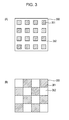
- an absorption grating 300 with a lattice-shaped pattern, in which transmissive portions 351 and light-shielding portions 352 are two-dimensionally arrayed as shown in Fig. 3(A) is used.
- an absorption grating 300 with a checker board designed pattern, in which transmissive portions 351 and light-shielding portions 352 are two-dimensionally arrayed as shown in Fig. 3(B) is used.
- phase grating and the absorption grating are merely an example, and various combinations may be made.
- the X-ray detector 170 is an element that can detect the information of the interference intensity distribution for the X-rays.
- a flat panel detector (FPD) capable of conversion into digital signals may be used.
- the information of the intensity distribution of the Moiré detected by the X-ray detector 170 is analyzed by an arithmetic unit 180 through an analysis method, which will be described later, so as to image a differential phase image or a phase image.
- the acquired differential phase image or phase image is an output image to be displayed on a display unit 190.
- the arithmetic unit 180 includes, for example, a central processing unit (CPU).
- the interference intensity distribution When the interference intensity distribution is formed, many rays of diffracted light are superposed and interfere with each other. Hence, the interference intensity distribution contains a fundamental frequency (hereinafter, referred to as carrier frequency) and a large number of harmonic components of the carrier frequency.
- carrier frequency a fundamental frequency
- a Moiré has a shape in which a carrier frequency component in the interference intensity distribution is spatially spread.
- g x y a x y + b x y ⁇ cos 2 ⁇ ⁇ ⁇ f 0 ⁇ x + ⁇ x y
- the Moiré is expressed by the sum of the background first term and the periodic second term.
- a(x, y) indicates the background
- b(x, y) indicates the amplitude of the carrier frequency component.
- a value f 0 indicates the carrier frequency of an interference fringe
- ⁇ (x, y) indicates the phase of the carrier frequency component.
- the carrier frequency component is generated because of interference between zeroth order diffracted light and plus first order diffracted light, and interference between zeroth order diffracted light and minus first order diffracted light.
- the carrier frequency component is generated due to interference between plus first order diffracted light and minus first order diffracted light.
- rays separated from one another by a distance Nd are superposed on one another at the phase grating 130.
- rays separated from one another by a distance 2Nd are superposed on one another at the phase grating 130. That is, such interference is shearing interference with a shear amount s corresponding to Nd in the case of the ⁇ /2 phase grating, or shearing interference with a shear amount s corresponding to 2Nd.
- phase image of the subject 120 at the position of the phase grating 130 is W(x, y)
- a phase ⁇ (x, y) and a phase image W(x, y) have the following relationship.
- ⁇ x y W ⁇ x + s , y - W x y
- the value s is typically very small. Thus, the following is obtained.
- the phase ⁇ (x, y) is information acquired by differentiating the phase image W(x, y) of the subject 120. Therefore, the phase image W(x, y) of the subject 120 can be acquired by integrating ⁇ (x, y).
- Expression (2) can be expressed as follows.
- g x y a x y + c x y ⁇ exp 2 ⁇ ⁇ ⁇ if 0 ⁇ x + c * x y ⁇ exp - 2 ⁇ ⁇ ⁇ if 0 ⁇ x
- the following is obtained.
- the information of the phase ⁇ (x, y) can be acquired by extracting a component of c(x, y) or a component of c*(x, y) from the interference fringe.
- G f x f y A f x f y + C ⁇ f x - f 0 , f y + C * ⁇ f x + f 0 , f y
- G(f x , f y ), A(f x , f y ), and C(f x , f y ) are two-dimensional Fourier transform for g(x, y), a(x, y), and c(x, y).
- Fig. 4 is a spectrum pattern of the interference intensity distribution when the one-dimensional grating is used. Typically, three peaks are generated as shown in Fig. 4 .
- the center peak is a peak mainly resulted from A(f x , f y ).
- peaks on both sides are carrier frequency peaks resulted from C(f x , f y ) and C*(f x , f y ). These peaks are generated at positions of ⁇ f 0 .
- a region containing the peak resulted from C(f x , f y ) or C*(f x , f y ) is extracted. For example, by extracting the periphery of the peak resulted from A(f x , f y ) and the periphery of the peak resulted from C(f x , f y ) or C*(f x , f y ), the peak resulted from C(f X , f y ) or C*(f x , f y ) is separated.
- the separated peak resulted from C(f x , f y ) or C*(f x , fy) is moved to an origin in a frequency space, and inverse Fourier transform is performed.
- inverse Fourier transform complex number information is acquired.
- the phase ⁇ (x, y), that is, differential phase information is acquired.
- Fig. 5(A) is an example of an intensity distribution of a Moiré when the ⁇ /2 phase grating with the checker board designed pattern ( Fig. 2(A) ) and the absorption grating with the lattice-shaped pattern ( Fig. 3(A) ) or the absorption grating with the checker board designed pattern ( Fig. 3(B) ) are used.
- Reference sign 510 denotes bright sections of the Moiré
- 520 denotes dark sections of the Moiré. It is to be noted that the intensity distribution of the Moiré is generated in an oblique direction even when the ⁇ phase grating with the checker board designed pattern ( Fig. 2(A) ) and the absorption grating with the checker board designed pattern ( Fig. 3(B) ) are used.
- Fig. 5(B) is an example of an intensity distribution of a Moiré when the ⁇ phase grating with the checker board designed pattern ( Fig. 2(A) ) and the absorption grating with the lattice-shaped pattern ( Fig. 3(A) ) are used.
- Reference sign 530 denotes bright sections of the Moiré
- 540 denotes dark sections of the Moiré.
- the intensity distribution of the Moiré is generated in vertical and horizontal directions.
- the intensity distribution of the Moiré is generated even when the phase grating with the lattice-shaped pattern ( Fig. 2(B) ) is used.
- Figs. 5(C) and 5(D) illustrate spatial frequency spectra acquired by performing processing for the intensity distributions of the Moiré shown in Figs. 5(A) and 5(B) by fast Fourier transform (FFT) which is a kind of Fourier transform.
- FFT fast Fourier transform
- the maximum spatial frequency that can be calculated by FFT is 1/(2P) when P is a pixel period of the X-ray detector 170.
- differential phase information in directions at ⁇ 45 degrees is acquired.
- differential phase information in X and Y directions is acquired.
- the differential phase information thus acquired is folded into (wrapped into) a region of 2 ⁇ .
- a true phase at any point on a screen is ⁇ (x, y) and a wrapped phase is ⁇ wap (x, y)
- the following relationship is established.
- n is an integer which is determined so that ⁇ wrap (x, y) is arranged in a region with a width of 2 ⁇ ,for example, a region from 0 to 2 ⁇ , or a region from - ⁇ to + ⁇ .
- phase unwrapping is performed for ⁇ (x, y) wrap to retrieve the value to the original ⁇ (x, y).
- the phase image W(x, y) of the subject can be acquired by integrating ⁇ (x, y) retrieved by Expression (8).
- the integration direction can be only the direction orthogonal to the grating rule direction. Owing to this, to correctly measure the phase image W(x, y), a side of the X-ray detector 170 parallel to the rule direction is irradiated with X-rays that are not transmitted through the subject 120 so that a recognized portion in the phase image W(x, y) is acquired in advance.
- phase image W(x, y) can be correctly measured even if the X-ray detector 170 is entirely irradiated with the X-rays transmitted through the subject 120.
- the information of the intensity distribution of the Moiré is acquired from the X-ray detector 170 (S610).
- a Fourier transform step is performed (S620) such that Fourier transform is performed for the information of the intensity distribution of the Moiré acquired in S610 and the spatial frequency spectrum is acquired.
- a peak separating step is performed (S631) such that the spectrum corresponding to the carrier frequency (spectrum having phase information) is extracted from the frequency space acquired in S620. If it is difficult to extract the spectrum corresponding to the carrier frequency, information of a peripheral region of the spectrum is extracted.
- phase retrieval step S630.
- ⁇ (x, y) is being wrapped, unwrapping is performed, and the true ⁇ (x, y) is acquired (S640).
- the step may be called phase unwrapping step. If ⁇ (x, y) is not wrapped, the step S640 may be omitted.
- ⁇ (x, y) is differential phase information (differential phase image).
- the X-ray imaging apparatus and the X-ray imaging method that can acquire a phase image of a subject by at least a single imaging operation can be provided.
- a program that causes a computer to execute the above steps can be provided.
- a spatial resolution is increased rather than the spatial frequency spectrum described in the first embodiment and shown in Fig. 5(C) .
- Fig. 7(B) illustrates a spatial frequency spectrum which is described in this embodiment.
- a fundamental period of a two-dimensional Moiré resulted from an interference intensity distribution and an absorption grating is determined with respect to a pixel period of the X-ray detector to achieve the following ratio.
- the orientation of the Moiré is adjusted to be inclined at 45 degrees to the pixel array.
- Fig. 7(A) illustrates the intensity distribution of the Moiré on the X-ray detector in this state.
- Reference sign 710 denotes a light-receiving surface of the X-ray detector
- 720 denotes bright sections of the Moiré
- d denotes a period of the Moiré
- P denotes a pixel period of the X-ray detector.
- the ⁇ /2 phase grating with the checker board designed pattern ( Fig. 2(A) ) and the absorption grating with the checker board designed pattern ( Fig. 3(B) ) are used.
- other phase grating and other absorption grating may be used as long as the intensity distribution of the Moiré to be generated is equivalent.
- Fig. 7(B) is a spatial frequency spectrum acquired by performing FFT for the intensity distribution of the Moiré shown in Fig. 7(A) .
- the spectrum space acquired by FFT is discrete data of nxn.
- the maximum frequency that can be expressed is 1/(2P) when P is a pixel period of the X-ray detector 170.
- the fundamental period of the Moiré is as follows.
- the carrier peak 711 is a peak corresponding to the carrier frequency of the intensity distribution of the Moiré.
- Two adjacent peaks included in four carrier peaks 711 are extracted in the form of a square region inclined at 45 degrees, the square region each having a side expressed as follows.
- the processing described in the first embodiment is performed. Accordingly, the phase image of the subject can be retrieved.
- the unnecessary peak 721 is a peak of a high-frequency component and a DC component and located at a position corresponding to the sum or difference of peak coordinates of carrier frequency components.
- the spectrum region to be extracted is an extraction region 731 located at the inner side with respect to the intermediate line between the peak of the carrier frequency and the unnecessary peak 721.
- the spatial frequency of the phase image to be retrieved in this embodiment is 1/2 of the size of the extraction region 731.
- the maximum frequency in the pixel array direction is 1/(4P), and the maximum frequency in the direction at 45 degrees is determined as follows.
- the minimum period on a pixel basis is the reciprocal of the maximum frequency.
- the minimum period in the pixel array direction is 4 pixels, and the minimum period in the direction at 45 degrees is as follows.
- FIG. 8 An X-ray imaging apparatus according to a third embodiment of the present invention will be described with reference to Fig. 8 .
- the spatial resolution is increased rather than the spatial frequency spectrum described in the first embodiment and shown in Fig. 5(D) .
- Fig. 8(B) illustrates a spatial frequency spectrum which is described in this embodiment.
- a fundamental period of a two-dimensional Moiré resulted from an interference intensity distribution and an absorption grating is determined to be three times a pixel period of the X-ray detector, and the orientation of the Moiré is aligned with the pixel array.
- Fig. 8(A) illustrates the intensity distribution of the Moiré on the X-ray detector in this state.
- Reference sign 810 denotes a light-receiving surface of the X-ray detector
- 820 denotes bright sections of the Moiré
- d denotes a period of the Moiré
- P denotes a pixel period of the X-ray detector.
- ⁇ phase grating with the checker board designed pattern ( Fig. 2(A) ) and the absorption grating with the lattice-shaped pattern ( Fig. 3(A) ) are used.
- other phase grating and other absorption grating may be used as long as the intensity distribution of the Moiré to be generated is equivalent.
- Fig. 8(A) is a spatial frequency spectrum acquired by performing FFT for the intensity distribution of the Moiré shown in Fig. 8(B) . Since the fundamental period of the Moiré is 3P in this embodiment, the absolute value of the carrier frequency is 1/(3P). Thus, a carrier peak 811 is generated at the following position.
- the carrier peak 811 is a peak corresponding to the carrier frequency of the intensity distribution of the Moiré. Similar to the second embodiment, erecting square regions each having a side of 1/(3P) are extracted for two adjacent peaks included in four carrier peaks 811. After the square regions are extracted, the processing described in the first embodiment is performed. Accordingly, the phase image of the subject can be retrieved.
- an unnecessary peak 821 is present in the spectrum space.
- the unnecessary peak 821 is a peak of a high-frequency component and a DC component and located at a position corresponding to the sum or difference of peak coordinates of carrier frequency components.
- the spectrum region to be extracted is an extraction region 831 located at the inner side with respect to the intermediate line between the peak of the carrier frequency and the unnecessary peak 821.
- the spatial frequency of the phase image to be retrieved in this embodiment is 1/2 of the size of the extraction region 831.
- the maximum frequency in the pixel array direction is 1/(6P), and the maximum frequency in the direction at 45 degrees is determined as follows.
- the minimum period is the reciprocal of the maximum frequency.
- the minimum period in the pixel array direction is 6 pixels, and the minimum period in the direction at 45 degrees is as follows.
- the spatial resolution in the direction at 45 degrees with respect to the pixel array in this embodiment is better than the second embodiment.
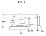
- the X-ray imaging apparatus of this embodiment is the X-ray imaging apparatus according to any one of the first to third embodiments including a subject moving device 900.
- the subject moving device 900 can move a subject 920 along the optical axis of X-rays.
- the X-ray detector has a magnification of imaging for the subject 920 of L1/L2 where L1 is a distance from an X-ray source 910 to an absorption grating 940, and L2 is a distance from the X-ray source 910 to the absorption grating 940.
- L2 becomes larger, and imaging can be performed with a low magnification.
- L2 becomes smaller, and imaging can be performed with a high magnification.
Landscapes
- Physics & Mathematics (AREA)
- Engineering & Computer Science (AREA)
- Health & Medical Sciences (AREA)
- Life Sciences & Earth Sciences (AREA)
- General Physics & Mathematics (AREA)
- Chemical & Material Sciences (AREA)
- Spectroscopy & Molecular Physics (AREA)
- Pathology (AREA)
- General Health & Medical Sciences (AREA)
- Biochemistry (AREA)
- Immunology (AREA)
- Analytical Chemistry (AREA)
- High Energy & Nuclear Physics (AREA)
- Medical Informatics (AREA)
- Nuclear Medicine, Radiotherapy & Molecular Imaging (AREA)
- Radiology & Medical Imaging (AREA)
- General Engineering & Computer Science (AREA)
- Theoretical Computer Science (AREA)
- Crystallography & Structural Chemistry (AREA)
- Computer Vision & Pattern Recognition (AREA)
- Quality & Reliability (AREA)
- Molecular Biology (AREA)
- Heart & Thoracic Surgery (AREA)
- Surgery (AREA)
- Animal Behavior & Ethology (AREA)
- Public Health (AREA)
- Veterinary Medicine (AREA)
- Biomedical Technology (AREA)
- Optics & Photonics (AREA)
- Biophysics (AREA)
- Analysing Materials By The Use Of Radiation (AREA)
- Apparatus For Radiation Diagnosis (AREA)
- Measurement Of Radiation (AREA)
Abstract
Description
- The present invention relates to an X-ray imaging apparatus and an X-ray imaging method.
- Since X-rays have high substance transmittivity and can perform imaging with high spatial resolution, for example, X-rays are used for nondestructive inspection of subjects in industrial use, and for radiography in medical use. In these cases, a contrast image is formed by using a difference of X-ray absorption coefficient for substances or living bodies when x-ray transmits through the substances or living bodies, depending on constituent elements or due to a difference in densities of the substances or living bodies. Such an imaging method is called X-ray absorption contrast method. However, a light element absorbs X-ray by a very small amount. It is difficult to image living soft tissues made of carbon, hydrogen, oxygen, etc., which are constituent elements of a living body, or soft materials by the X-ray absorption contrast method.
- On the contrary to this, as a method for clearly imaging even tissues made of light elements, X-ray phase-contrast methods using a phase difference of X-rays have been studied since the nineteen-nineties.
- A large number of X-ray phase-contrast methods have been developed. One of such methods may be an X-ray phase-contrast method using Talbot interference as a method capable of using a conventional X-ray tube (Patent literature 1).
- The method using the Talbot interference described in
Patent literature 1 includes an X-ray tube that generates X-rays, a phase grating that modulates the phase of the X-rays and generates an interference intensity distribution, an absorption grating that converts the interference intensity distribution into an intensity distribution of a Moiré, and an X-ray detector that detects the interference intensity distribution. - In the method described in
Patent literature 1, imaging is performed by scanning the absorption grating along the direction of the grating period. With this scanning, the Moiré to be detected is moved. When the scanning length reaches one period of the absorption grating, the image of the Moiré is retrieved to the original state. Arithmetic processing is performed using at least three images of image data during scanning, and thus a differential phase image is acquired. -
- PTL 1:
US Patent No. 7180979 - The method described in
Patent literature 1 acquires a differential phase image by performing imaging for at least three images, and calculates a phase image from the differential phase image. - Since the method described in
Patent literature 1 has to perform imaging for at least three images, if a subject is moved during imaging, image quality may be degraded. - Also, if the period of time for imaging increases, the X-ray dose for a subject increases. It is not desirable for medical use.
- Accordingly, an object of the present invention is to provide an X-ray imaging apparatus and an X-ray imaging method that can acquire a differential phase image or a phase image of a subject by at least a single imaging operation.
- An X-ray imaging apparatus according to the present invention includes an X-ray source; a phase grating that transmits X-rays from the X-ray source and forms an interference intensity distribution by the Talbot effect; an absorption grating that partly shields the interference intensity distribution formed by the phase grating and generates a Moiré; a detector that detects an intensity distribution of the Moire generated by the absorption grating; and an arithmetic unit that images information of a subject from the intensity distribution of the Moiré detected by the detector and outputs the information. The arithmetic unit executes a process including a Fourier transform step of performing Fourier transform for the intensity distribution of the Moiré acquired by the detector and acquiring a spatial frequency spectrum, and a phase retrieval step of separating a spectrum corresponding to a carrier frequency from the spatial frequency spectrum acquired in the Fourier transform step, performing inverse Fourier transform for the separated spectrum, and acquiring a differential phase image.
- With the present invention, the X-ray imaging apparatus and the X-ray imaging method that can acquire a differential phase image or a phase image of a subject by at least a single imaging operation can be provided.
-
- [
Fig. 1] Fig. 1 is an explanatory view of an X-ray imaging apparatus according to a first embodiment of the present invention. - [
Fig. 2] Fig. 2 provides explanatory views of two-dimensional phase gratings according to second and third embodiments of the present invention. - [
Fig. 3] Fig. 3 provides explanatory views of two-dimensional phase gratings according to the first and second embodiments of the present invention. - [
Fig. 4] Fig. 4 illustrates a spectrum pattern of an interference intensity distribution. - [
Fig. 5] Fig. 5 illustrates intensity distributions of Moiré and spectrum patterns when the two-dimensional phase grating is used. - [
Fig. 6] Fig. 6 is an explanatory view of a flowchart of an analyzing method executed by an arithmetic unit according to the present invention. - [
Fig. 7] Fig. 7 provides explanatory views of an intensity distribution of a Moiré and a spatial frequency spectrum according to the second embodiment of the present invention. - [
Fig. 8] Fig. 8 provides explanatory views of an intensity distribution of a Moiré and a spatial frequency spectrum according to the third embodiment of the present invention. - [
Fig. 9] Fig. 9 is an explanatory view of a zoom mechanism according to a fourth embodiment of the present invention. -
Fig. 1 illustrates an exemplary configuration of an X-ray imaging apparatus using Talbot interference. A process to acquire a phase image by using the X-ray imaging apparatus will be described in detail. -
X-rays 111 generated by anX-ray source 110 are transmitted through asubject 120. When theX-rays 111 are transmitted through thesubject 120, the phase of theX-rays 111 is changed and theX-rays 111 is absorbed depending on the composition, shape, etc., of thesubject 120. - The X-rays may be continuous X-rays or characteristic X-rays. The wavelength of the X-rays is selected in a range from about 0.1Å to 5Å. A wavelength selection filter and/or a grating for a source may be provided downstream of the
X-ray source 110. - The
X-rays 111 transmitted through thesubject 120 is transmitted through aphase grating 130. Then, thex-rays 111 form aninterference intensity distribution 140 by the Talbot effect. - The
phase grating 130 is arranged upstream or downstream of thesubject 120. - The
phase grating 130 includesphase advance portions 131 andphase lag portions 132, which are formed by periodically changing the thickness of an X-ray transmissive member. The phase advanceportions 131 and thephase lag portions 132 may be formed such that the phase of the X-rays transmitted through thephase advance portions 131 is different from the phase of the X-rays transmitted through thephase lag portions 132. For example, the phase of the X-rays transmitted through thephase advance portions 131 is advanced by π relative to the phase of the X-rays transmitted through thephase lag portions 132. The amount of change in thickness is determined by the wavelength of the X-rays to be used, and the member. - The
phase grating 130 typically modulates the phase of the X-rays transmitted through thephase advance portions 131 by π or π/2 relative to the phase of the X-rays transmitted through thephase lag portions 132. The former grating may be called π phase grating, and the later grating may be called π/2 phase grating. The modulation amount of a phase is only required to be periodic. For example, modulation may be π/3 modulation. - The
phase grating 130 may have a one-dimensional linear shape. Alternatively, thephase grating 130 may have a two-dimensional checker board designed pattern as shown inFig. 2(A) . Still alternatively, the phase grating 130 may have a lattice-shaped pattern as shown inFig. 2(B) . Referring toFig. 2 , reference sign d denotes a period, 201 denotes a two-dimensional phase grating, 210 denotes phase advance portions, and 220 denotes phase lag portions. - The shape of each
phase advance portion 210 or eachphase lag portion 220 is a square inFigs. 2(A) and 2(B) , however, the outer edge thereof may be deformed into a circular shape through fabrication. Even when the shape is deformed into the circular shape, the deformed portion can be used as a phase grating. - If the phase grating 130 has a one-dimensional period, phase gradient information only in a one-dimensional direction of the subject 120 is acquired. In contrast, if the phase grating 130 has a two-dimensional period, phase gradient information in two-dimensional directions can be acquired, which is advantageous.
- The material of the phase grating 130 is desirably a substance that transmits X-rays. For example, the material may be silicon.
- An interference intensity distribution formed after the X-rays are transmitted through the phase grating 130 most clearly appears at a position, at which, when Z0 is a distance from the X-ray source to the phase grating 130 and Z1 is a distance from the phase grating 130 to an
absorption grating 150, the distance Z1 satisfies the following Expression (1). Herein, the "interference intensity distribution" is a periodic intensity distribution in which the grating period of the phase grating 130 is reflected. - In Expression (1), λ is a wavelength of the X-rays and d is a grating period of the phase grating 130.
-

- λ phase grating in one-dimensional array: N = n/4 - 1/8
- π/2 phase grating in one-dimensional array: N = n - 1/2
- phase grating with checker board designed pattern in two-dimensional array: N = n/4 - 1/8
- π/2 phase grating with checker board designed pattern in two dimensions: N = n/2 - 1/4
- The period of the interference intensity distribution is typically smaller than the pixel size of the
X-ray detector 170. Hence, the interference intensity distribution cannot be detected in this state. Therefore, the absorption grating 150 is used to generate a Moiré with a period that is larger than the pixel size of theX-ray detector 170, so that theX-ray detector 170 detects the intensity distribution of the Moiré. Theabsorption grating 150 is desirably provided at a position separated from the phase grating 130 by the distance Z1. - The
absorption grating 150 includestransmissive portions 151 and light-shieldingportions 152 which are periodically arrayed and arranged to partly shield bright sections of theinterference intensity distribution 140 formed by the phase grating 130. Eachtransmissive portion 151 does not have to have an opening penetrating through the absorption grating 150 as long as thetransmissive portion 151 can partly transmit the X-rays. The material of the absorption grating 150 is not particularly limited as long as the material has high absorbency for the X-rays. The material may be, for example, gold. - The period of the absorption grating 150 is equivalent to or slightly different from the period of the interference intensity distribution.
- If the absorption grating with a period equivalent to the period of the interference intensity distribution is used, a Moiré is generated by in-plane rotation of the absorption grating. When the period of the interference intensity distribution is represented by D, and the angle defined between the orientation of bright and dark sections in the interference intensity distribution and the orientation of the absorption grating is represented by θ (here, θ « 1), the period Dm of the Moiré is D/θ.
- In contrast, if the absorption grating with the period slightly different from the period of the interference intensity distribution is used, a Moiré is generated without in-plane rotation of the absorption grating. When the period of the absorption grating is expressed by Da = D + δ (here, δ « D), the period Dm of the Moiré is D2/δ.
- In the absorption grating 150, the
transmissive portions 151 may be one- or two-dimensionally arrayed. - For example, if a π phase grating with a checker board designed pattern shown in
Fig. 2(A) is used, an absorption grating 300 with a lattice-shaped pattern, in which transmissiveportions 351 and light-shieldingportions 352 are two-dimensionally arrayed as shown inFig. 3(A) , is used. If a π/2 phase grating a checker board designed pattern shown inFig. 2(A) is used, an absorption grating 300 with a checker board designed pattern, in which transmissiveportions 351 and light-shieldingportions 352 are two-dimensionally arrayed as shown inFig. 3(B) , is used. - The aforementioned combination of the phase grating and the absorption grating is merely an example, and various combinations may be made.
- Information of the interference intensity distribution for the X-rays transmitted through the absorption grating 140 is detected as an intensity distribution of the Moiré by the
X-ray detector 170. TheX-ray detector 170 is an element that can detect the information of the interference intensity distribution for the X-rays. For example, a flat panel detector (FPD) capable of conversion into digital signals may be used. - The information of the intensity distribution of the Moiré detected by the
X-ray detector 170 is analyzed by anarithmetic unit 180 through an analysis method, which will be described later, so as to image a differential phase image or a phase image. The acquired differential phase image or phase image is an output image to be displayed on adisplay unit 190. Thearithmetic unit 180 includes, for example, a central processing unit (CPU). - An analysis method for acquiring a phase image from the information of the intensity distribution of the Moiré acquired by the detector will be described below. Then, a processing step executed by the arithmetic unit will be described.
- When the interference intensity distribution is formed, many rays of diffracted light are superposed and interfere with each other. Hence, the interference intensity distribution contains a fundamental frequency (hereinafter, referred to as carrier frequency) and a large number of harmonic components of the carrier frequency. A Moiré has a shape in which a carrier frequency component in the interference intensity distribution is spatially spread. When the one-dimensional phase grating with a rule orthogonal to the x axis is used, the Moiré can be expressed by Expression (2).
-

- In contrast, when the two-dimensional phase grating is used, a carrier frequency component in the y direction is superposed on the result of Expression (2).
- In Expression (2), the Moiré is expressed by the sum of the background first term and the periodic second term. Herein, a(x, y) indicates the background, and b(x, y) indicates the amplitude of the carrier frequency component. Also, a value f0 indicates the carrier frequency of an interference fringe, and φ(x, y) indicates the phase of the carrier frequency component.
- When the π/2 phase grating with the checker board designed pattern is used as the phase grating 130, the carrier frequency component is generated because of interference between zeroth order diffracted light and plus first order diffracted light, and interference between zeroth order diffracted light and minus first order diffracted light. When then π phase grating with the checker board designed pattern is used as the phase grating 130, the carrier frequency component is generated due to interference between plus first order diffracted light and minus first order diffracted light.
- For the zeroth order diffracted light and the first order diffracted light, rays separated from one another by a distance Nd are superposed on one another at the phase grating 130. For the plus first order diffracted light and the minus first order diffracted light, rays separated from one another by a distance 2Nd are superposed on one another at the phase grating 130. That is, such interference is shearing interference with a shear amount s corresponding to Nd in the case of the π/2 phase grating, or shearing interference with a shear amount s corresponding to 2Nd.
- When the phase image of the subject 120 at the position of the phase grating 130 is W(x, y), a phase φ(x, y) and a phase image W(x, y) have the following relationship.
-

- The value s is typically very small. Thus, the following is obtained.
-

- Regarding Expression (3), it is found that the phase φ(x, y) is information acquired by differentiating the phase image W(x, y) of the subject 120. Therefore, the phase image W(x, y) of the subject 120 can be acquired by integrating φ(x, y).
- Meanwhile, the phase φ(x, y) can be acquired from Expression (2) by Fourier transform. That is, Expression (2) can be expressed as follows.
-

-

- Therefore, the information of the phase φ(x, y) can be acquired by extracting a component of c(x, y) or a component of c*(x, y) from the interference fringe.
- Herein, by the Fourier transform, Expression (4) is as follows.
-

- Herein, G(fx, fy), A(fx, fy), and C(fx, fy) are two-dimensional Fourier transform for g(x, y), a(x, y), and c(x, y).
-
Fig. 4 is a spectrum pattern of the interference intensity distribution when the one-dimensional grating is used. Typically, three peaks are generated as shown inFig. 4 . The center peak is a peak mainly resulted from A(fx, fy). In contrast, peaks on both sides are carrier frequency peaks resulted from C(fx, fy) and C*(fx, fy). These peaks are generated at positions of ±f0. - Next, a region containing the peak resulted from C(fx, fy) or C*(fx, fy) is extracted. For example, by extracting the periphery of the peak resulted from A(fx, fy) and the periphery of the peak resulted from C(fx, fy) or C*(fx, fy), the peak resulted from C(fX, fy) or C*(fx, fy) is separated.
- Next, the separated peak resulted from C(fx, fy) or C*(fx, fy) is moved to an origin in a frequency space, and inverse Fourier transform is performed. By inverse Fourier transform, complex number information is acquired. With the complex number information, the phase φ(x, y), that is, differential phase information is acquired.
-
Fig. 5(A) is an example of an intensity distribution of a Moiré when the π/2 phase grating with the checker board designed pattern (Fig. 2(A) ) and the absorption grating with the lattice-shaped pattern (Fig. 3(A) ) or the absorption grating with the checker board designed pattern (Fig. 3(B) ) are used.Reference sign 510 denotes bright sections of the Moiré, and 520 denotes dark sections of the Moiré. It is to be noted that the intensity distribution of the Moiré is generated in an oblique direction even when the π phase grating with the checker board designed pattern (Fig. 2(A) ) and the absorption grating with the checker board designed pattern (Fig. 3(B) ) are used. -
Fig. 5(B) is an example of an intensity distribution of a Moiré when the π phase grating with the checker board designed pattern (Fig. 2(A) ) and the absorption grating with the lattice-shaped pattern (Fig. 3(A) ) are used.Reference sign 530 denotes bright sections of the Moiré, and 540 denotes dark sections of the Moiré. In this case, the intensity distribution of the Moiré is generated in vertical and horizontal directions. - It is to be noted that the intensity distribution of the Moiré is generated even when the phase grating with the lattice-shaped pattern (
Fig. 2(B) ) is used. -
Figs. 5(C) and 5(D) illustrate spatial frequency spectra acquired by performing processing for the intensity distributions of the Moiré shown inFigs. 5(A) and 5(B) by fast Fourier transform (FFT) which is a kind of Fourier transform. The maximum spatial frequency that can be calculated by FFT is 1/(2P) when P is a pixel period of theX-ray detector 170. - The peripheries of two
peaks peaks - Herein, in
Fig. 5(C) , differential phase information in directions at ±45 degrees is acquired. InFig. 5(D) , differential phase information in X and Y directions is acquired. - In many cases, the differential phase information thus acquired is folded into (wrapped into) a region of 2π. In particular, when a true phase at any point on a screen is φ(x, y) and a wrapped phase is φwap(x, y), the following relationship is established.
-

- With such information, phase unwrapping is performed for φ(x, y)wrap to retrieve the value to the original φ(x, y).
- The phase image W(x, y) of the subject can be acquired by integrating φ(x, y) retrieved by Expression (8).
-

- When the one-dimensional grating is used, the integration direction can be only the direction orthogonal to the grating rule direction. Owing to this, to correctly measure the phase image W(x, y), a side of the
X-ray detector 170 parallel to the rule direction is irradiated with X-rays that are not transmitted through the subject 120 so that a recognized portion in the phase image W(x, y) is acquired in advance. - When the two-dimensional grating is used, integration can be performed in two directions. The phase image W(x, y) can be correctly measured even if the
X-ray detector 170 is entirely irradiated with the X-rays transmitted through the subject 120. - With regard to the above description, an example of a processing flow executed by the
arithmetic unit 180 will be illustrated inFig. 6 . - First, the information of the intensity distribution of the Moiré is acquired from the X-ray detector 170 (S610).
- Next, a Fourier transform step is performed (S620) such that Fourier transform is performed for the information of the intensity distribution of the Moiré acquired in S610 and the spatial frequency spectrum is acquired.
- Next, a peak separating step is performed (S631) such that the spectrum corresponding to the carrier frequency (spectrum having phase information) is extracted from the frequency space acquired in S620. If it is difficult to extract the spectrum corresponding to the carrier frequency, information of a peripheral region of the spectrum is extracted.
- Next, the spectrum extracted in S631 is moved to the origin in the frequency space, and inverse Fourier transform is performed (S632). Accordingly, complex number information having phase information can be acquired.
- Next, the phase φ(x, y) as differential phase information is acquired from the complex number information acquired in S632 (S633). It is to be noted that the steps S631, S632, and S633 may be collectively called phase retrieval step (S630).
- Next, when φ(x, y) is being wrapped, unwrapping is performed, and the true φ(x, y) is acquired (S640). The step may be called phase unwrapping step. If φ(x, y) is not wrapped, the step S640 may be omitted. Herein, φ(x, y) is differential phase information (differential phase image).
- Next, by integrating φ(x, y), the phase image W(x, y) is acquired (S650).
- With the above configuration, the X-ray imaging apparatus and the X-ray imaging method that can acquire a phase image of a subject by at least a single imaging operation can be provided. In addition, a program that causes a computer to execute the above steps can be provided.
- An X-ray imaging apparatus according to a second embodiment of the present invention will be described with reference to
Fig. 7 . In this embodiment, a spatial resolution is increased rather than the spatial frequency spectrum described in the first embodiment and shown inFig. 5(C) . -
Fig. 7(B) illustrates a spatial frequency spectrum which is described in this embodiment. To acquire such a frequency spectrum, a fundamental period of a two-dimensional Moiré resulted from an interference intensity distribution and an absorption grating is determined with respect to a pixel period of the X-ray detector to achieve the following ratio. -

-
Fig. 7(A) illustrates the intensity distribution of the Moiré on the X-ray detector in this state.Reference sign 710 denotes a light-receiving surface of the X-ray detector, 720 denotes bright sections of the Moiré, d denotes a period of the Moiré, and P denotes a pixel period of the X-ray detector. In this embodiment, the π/2 phase grating with the checker board designed pattern (Fig. 2(A) ) and the absorption grating with the checker board designed pattern (Fig. 3(B) ) are used. However, other phase grating and other absorption grating may be used as long as the intensity distribution of the Moiré to be generated is equivalent. -
Fig. 7(B) is a spatial frequency spectrum acquired by performing FFT for the intensity distribution of the Moiré shown inFig. 7(A) . When the number of pixels in the array is n for each of the vertical and horizontal sides, the spectrum space acquired by FFT is discrete data of nxn. The maximum frequency that can be expressed is 1/(2P) when P is a pixel period of theX-ray detector 170. - In this embodiment, the fundamental period of the Moiré is as follows.
-

-

- Also, since the orientation of the Moiré is inclined at 45 degrees, a
carrier peak 711 is generated at the following position. -

carrier peak 711 is a peak corresponding to the carrier frequency of the intensity distribution of the Moiré. - Two adjacent peaks included in four
carrier peaks 711 are extracted in the form of a square region inclined at 45 degrees, the square region each having a side expressed as follows. -

- If the spectrum region is extracted by a large area as possible, the spatial resolution can be increased. However, in addition to the peak of the carrier frequency, an
unnecessary peak 721 is present in the spectrum space. Theunnecessary peak 721 is a peak of a high-frequency component and a DC component and located at a position corresponding to the sum or difference of peak coordinates of carrier frequency components. - If the extraction region is too large, the region around the
unnecessary peak 721 may be included. A correct phase image is no longer provided due to the effect of theunnecessary peak 721. Accordingly, the spectrum region to be extracted is anextraction region 731 located at the inner side with respect to the intermediate line between the peak of the carrier frequency and theunnecessary peak 721. - The spatial frequency of the phase image to be retrieved in this embodiment is 1/2 of the size of the
extraction region 731. Thus, as it is found inFig. 7(B) , the maximum frequency in the pixel array direction is 1/(4P), and the maximum frequency in the direction at 45 degrees is determined as follows. -

-

Fig. 5(C) , the extraction region inFig. 7(B) is larger than the extraction region inFig. 5(C) , and hence, the spatial frequency that can be retrieved is larger. Thus, with this embodiment, the spatial frequency can be increased as compared with the aforementioned embodiment. - An X-ray imaging apparatus according to a third embodiment of the present invention will be described with reference to
Fig. 8 . In this embodiment, the spatial resolution is increased rather than the spatial frequency spectrum described in the first embodiment and shown inFig. 5(D) . -
Fig. 8(B) illustrates a spatial frequency spectrum which is described in this embodiment. To acquire such a frequency spectrum, a fundamental period of a two-dimensional Moiré resulted from an interference intensity distribution and an absorption grating is determined to be three times a pixel period of the X-ray detector, and the orientation of the Moiré is aligned with the pixel array. -
Fig. 8(A) illustrates the intensity distribution of the Moiré on the X-ray detector in this state.Reference sign 810 denotes a light-receiving surface of the X-ray detector, 820 denotes bright sections of the Moiré, d denotes a period of the Moiré, and P denotes a pixel period of the X-ray detector. In this embodiment, then π phase grating with the checker board designed pattern (Fig. 2(A) ) and the absorption grating with the lattice-shaped pattern (Fig. 3(A) ) are used. However, other phase grating and other absorption grating may be used as long as the intensity distribution of the Moiré to be generated is equivalent. -
Fig. 8(A) is a spatial frequency spectrum acquired by performing FFT for the intensity distribution of the Moiré shown inFig. 8(B) . Since the fundamental period of the Moiré is 3P in this embodiment, the absolute value of the carrier frequency is 1/(3P). Thus, acarrier peak 811 is generated at the following position. -

carrier peak 811 is a peak corresponding to the carrier frequency of the intensity distribution of the Moiré. Similar to the second embodiment, erecting square regions each having a side of 1/(3P) are extracted for two adjacent peaks included in four carrier peaks 811. After the square regions are extracted, the processing described in the first embodiment is performed. Accordingly, the phase image of the subject can be retrieved. - However, in this embodiment, in addition to the peak of the carrier frequency, an
unnecessary peak 821 is present in the spectrum space. Theunnecessary peak 821 is a peak of a high-frequency component and a DC component and located at a position corresponding to the sum or difference of peak coordinates of carrier frequency components. Accordingly, the spectrum region to be extracted is anextraction region 831 located at the inner side with respect to the intermediate line between the peak of the carrier frequency and theunnecessary peak 821. - The spatial frequency of the phase image to be retrieved in this embodiment is 1/2 of the size of the
extraction region 831. Thus, referring toFig. 8(B) , the maximum frequency in the pixel array direction is 1/(6P), and the maximum frequency in the direction at 45 degrees is determined as follows. -

-

- An X-ray imaging apparatus according to a third embodiment of the present invention will be described with reference to
Fig. 9 . The X-ray imaging apparatus of this embodiment is the X-ray imaging apparatus according to any one of the first to third embodiments including asubject moving device 900. Thesubject moving device 900 can move a subject 920 along the optical axis of X-rays. - The X-ray detector has a magnification of imaging for the subject 920 of L1/L2 where L1 is a distance from an
X-ray source 910 to anabsorption grating 940, and L2 is a distance from theX-ray source 910 to theabsorption grating 940. - Thus, as the subject 920 is moved closer to a phase grating 930, L2 becomes larger, and imaging can be performed with a low magnification. In contrast, as the subject 920 is moved closer to the
X-ray source 910, L2 becomes smaller, and imaging can be performed with a high magnification. -
- 110
- X-ray source
- 111
- X-ray
- 120
- subject
- 130
- phase grating
- 150
- absorption grating
- 151
- transmissive portion
- 152
- light-shielding portion
- 170
- X-ray detector
- 180
- arithmetic unit
Claims (13)
- An X-ray imaging apparatus comprising:an X-ray source;a phase grating that transmits X-rays from the X-ray source and forms an interference intensity distribution by the Talbot effect;an absorption grating that partly shields the interference intensity distribution formed by the phase grating and generates a Moiré;a detector that detects an intensity distribution of the Moiré generated by the absorption grating; andan arithmetic unit that images information of a subject from the intensity distribution of the Moiré detected by the detector and outputs the information,wherein the arithmetic unit executes a process including
the Fourier transform step of performing Fourier transform for the intensity distribution of the Moiré acquired by the detector and acquiring a spatial frequency spectrum, and
a phase retrieval step of separating a spectrum corresponding to a carrier frequency from the spatial frequency spectrum acquired in the Fourier transform step, performing inverse Fourier transform for the separated spectrum, and acquiring a differential phase image. - The X-ray imaging apparatus according to claim 1,
wherein the arithmetic unit executes a step of integrating the differential phase image acquired in the phase retrieval step and acquiring a phase image. - The X-ray imaging apparatus according to claim 1,
wherein the arithmetic unit executes a phase unwrapping step of unwrapping the differential phase image acquired in the phase retrieval step. - The X-ray imaging apparatus according to claim 1,
wherein the phase grating includes phase advance portions and phase lag portions that are two-dimensionally and periodically arranged. - The X-ray imaging apparatus according to claim 4,
wherein the phase grating includes the phase advance portions and the phase lag portions that are arranged in a checker board designed pattern. - The X-ray imaging apparatus according to claim 4,
wherein the phase grating is configured such that a difference between a phase of X-rays transmitted through the phase advance portions and a phase of X-rays transmitted through the phase lag portions is π/2 or π. - The X-ray imaging apparatus according to claim 1,
wherein the phase grating, the absorption grating, and the detector are adjusted such that, in the spectrum space acquired in the Fourier transform step, the spectrum corresponding to the carrier frequency is generated at a position expressed as follows,
where P is a pixel period of the detector. - The X-ray imaging apparatus according to claim 7,
wherein the absorption grating has a period of the Moiré expressed as follows,
the orientation of the Moiré being arranged at 45 degrees to a pixel array of the detector, and
wherein, to separate the spectrum corresponding to the carrier frequency, the arithmetic unit executes a step of extracting two square regions from a frequency space of an image of the Moiré acquired by the detector, each of the square regions having a side expressed as follows,
the square regions being inclined at 45 degrees to a pixel array direction. - The X-ray imaging apparatus according to claim 1,
wherein the phase grating, the absorption grating, and the detector are adjusted such that, in the spectrum space acquired in the Fourier transform step, the spectrum corresponding to the carrier frequency is generated at a position expressed as follows,
where P is a pixel period of the detector. - The X-ray imaging apparatus according to claim 9,
wherein the absorption grating is arranged such that a period of the Moiré is 3P and the orientation of the Moiré is aligned with a pixel array of the detector, and
wherein, to separate the spectrum corresponding to the carrier frequency, the arithmetic unit executes a step of extracting two square regions from a frequency space of an image of the Moiré acquired by the detector, each of the square regions erecting with respect to a pixel array direction and having a side of 1/(3P). - The X-ray imaging apparatus according to claim 1, further comprising a subject moving device that can move the subject in an optical-axis direction of the X-rays.
- An X-ray imaging method used in an X-ray imaging apparatus, the method comprising:a step of causing X-rays to be transmitted and forming an interference intensity distribution by the Talbot effect;a step of partly shielding the interference intensity distribution and generating a Moiré;a step of detecting an intensity distribution of the Moiré;a step of performing the Fourier transform for the intensity distribution of the Moiré and acquiring a spatial frequency spectrum;a step of separating a spectrum corresponding to a carrier frequency from the spatial frequency spectrum, performing inverse Fourier transform for the separated spectrum, and acquiring a differential phase image; anda step of integrating the differential phase image and acquiring phase image.
- A program causing a computer to execute a process comprising:a step of causing X-rays to be transmitted and forming an interference intensity distribution by a Talbot effect;a step of partly shielding the interference intensity distribution and generating a Moiré;a step of detecting an intensity distribution of the Moiré;a step of performing Fourier transform for the intensity distribution of the Moiré and acquiring a spatial frequency spectrum;a step of separating a spectrum corresponding to a carrier frequency from the spatial frequency spectrum, performing inverse Fourier transform for the separated spectrum, and acquiring a differential phase image; anda step of integrating the differential phase image and acquiring a phase image.
Applications Claiming Priority (2)
| Application Number | Priority Date | Filing Date | Title |
|---|---|---|---|
| JP2008278425 | 2008-10-29 | ||
| PCT/JP2009/068434 WO2010050483A1 (en) | 2008-10-29 | 2009-10-27 | X-ray imaging device and x-ray imaging method |
Publications (3)
| Publication Number | Publication Date |
|---|---|
| EP2343537A1 true EP2343537A1 (en) | 2011-07-13 |
| EP2343537A4 EP2343537A4 (en) | 2012-05-02 |
| EP2343537B1 EP2343537B1 (en) | 2019-04-10 |
Family
ID=41664696
Family Applications (2)
| Application Number | Title | Priority Date | Filing Date |
|---|---|---|---|
| EP09823593.0A Active EP2343537B1 (en) | 2008-10-29 | 2009-10-27 | X-ray imaging device and x-ray imaging method |
| EP09788095A Withdrawn EP2342551A1 (en) | 2008-10-29 | 2009-10-28 | Analysis method, radiation imaging apparatus using analysis method, and analysis program for executing analysis method |
Family Applications After (1)
| Application Number | Title | Priority Date | Filing Date |
|---|---|---|---|
| EP09788095A Withdrawn EP2342551A1 (en) | 2008-10-29 | 2009-10-28 | Analysis method, radiation imaging apparatus using analysis method, and analysis program for executing analysis method |
Country Status (8)
| Country | Link |
|---|---|
| US (5) | US8520799B2 (en) |
| EP (2) | EP2343537B1 (en) |
| JP (4) | JP5174180B2 (en) |
| KR (1) | KR101258927B1 (en) |
| CN (3) | CN102197303A (en) |
| DE (1) | DE112009002606B4 (en) |
| RU (1) | RU2519663C2 (en) |
| WO (2) | WO2010050483A1 (en) |
Cited By (2)
| Publication number | Priority date | Publication date | Assignee | Title |
|---|---|---|---|---|
| WO2012038857A1 (en) * | 2010-09-20 | 2012-03-29 | Koninklijke Philips Electronics N.V. | Phase gradient unwrapping in differential phase contrast imaging |
| EP3809121A4 (en) * | 2018-06-12 | 2022-03-09 | University of Tsukuba | PHASE IMAGE CAPTURE METHOD AND PHASE IMAGE CAPTURE DEVICE USING THE SAME |
Families Citing this family (109)
| Publication number | Priority date | Publication date | Assignee | Title |
|---|---|---|---|---|
| JP5339975B2 (en) * | 2008-03-13 | 2013-11-13 | キヤノン株式会社 | Phase grating used for X-ray phase imaging, X-ray phase contrast image imaging apparatus using the phase grating, X-ray computed tomography system |
| JP5174180B2 (en) * | 2008-10-29 | 2013-04-03 | キヤノン株式会社 | X-ray imaging apparatus and X-ray imaging method |
| CN101943668B (en) * | 2009-07-07 | 2013-03-27 | 清华大学 | X-ray dark-field imaging system and method |
| JP5586899B2 (en) * | 2009-08-26 | 2014-09-10 | キヤノン株式会社 | X-ray phase grating and manufacturing method thereof |
| US8532252B2 (en) * | 2010-01-27 | 2013-09-10 | Canon Kabushiki Kaisha | X-ray shield grating, manufacturing method therefor, and X-ray imaging apparatus |
| JP5631013B2 (en) * | 2010-01-28 | 2014-11-26 | キヤノン株式会社 | X-ray imaging device |
| JP5725870B2 (en) * | 2010-02-22 | 2015-05-27 | キヤノン株式会社 | X-ray imaging apparatus and X-ray imaging method |
| JP5796976B2 (en) * | 2010-05-27 | 2015-10-21 | キヤノン株式会社 | X-ray imaging device |
| JP5731214B2 (en) * | 2010-08-19 | 2015-06-10 | 富士フイルム株式会社 | Radiation imaging system and image processing method thereof |
| EP2612299B1 (en) * | 2010-09-03 | 2015-11-18 | Koninklijke Philips N.V. | Regularized phase retrieval in differential phase-contrast imaging |
| WO2012042924A1 (en) * | 2010-09-29 | 2012-04-05 | コニカミノルタエムジー株式会社 | Method for displaying medical images and medical image display system |
| JP2012103237A (en) * | 2010-10-14 | 2012-05-31 | Canon Inc | Imaging apparatus |
| CN103189739B (en) * | 2010-10-19 | 2015-12-02 | 皇家飞利浦电子股份有限公司 | Differential phase contrast's imaging |
| RU2572644C2 (en) * | 2010-10-19 | 2016-01-20 | Конинклейке Филипс Электроникс Н.В. | Differential phase-contrast imaging |
| JP5875280B2 (en) | 2010-10-20 | 2016-03-02 | キヤノン株式会社 | Imaging device using Talbot interference and method for adjusting imaging device |
| EP2633813B1 (en) * | 2010-10-29 | 2015-02-25 | FUJIFILM Corporation | Phase contrast radiation imaging device |
| JP2012095865A (en) * | 2010-11-02 | 2012-05-24 | Fujifilm Corp | Radiographic apparatus and radiographic system |
| JP2012143553A (en) * | 2010-12-24 | 2012-08-02 | Fujifilm Corp | Radiographic apparatus and radiation image detector |
| JP5777360B2 (en) * | 2011-03-14 | 2015-09-09 | キヤノン株式会社 | X-ray imaging device |
| JP5915645B2 (en) * | 2011-03-23 | 2016-05-11 | コニカミノルタ株式会社 | Medical image display system |
| JP2012200567A (en) * | 2011-03-28 | 2012-10-22 | Fujifilm Corp | Radiographic system and radiographic method |
| JP2014113168A (en) * | 2011-03-29 | 2014-06-26 | Fujifilm Corp | Radiographic system and radiographic method |
| JP5475925B2 (en) | 2011-04-20 | 2014-04-16 | 富士フイルム株式会社 | Radiation imaging apparatus and image processing method |
| JP2014132913A (en) * | 2011-04-25 | 2014-07-24 | Fujifilm Corp | Radiation image-capturing system, and radiation image-capturing method |
| JP5787597B2 (en) * | 2011-04-26 | 2015-09-30 | キヤノン株式会社 | Imaging device |
| JP2012236005A (en) * | 2011-04-26 | 2012-12-06 | Fujifilm Corp | Radiation imaging apparatus |
| JP2014155508A (en) * | 2011-06-08 | 2014-08-28 | Fujifilm Corp | Radiography system |
| JP2014155509A (en) * | 2011-06-10 | 2014-08-28 | Fujifilm Corp | Radiographic system |
| JP5885405B2 (en) * | 2011-06-13 | 2016-03-15 | キヤノン株式会社 | Imaging apparatus, interference fringe analysis program, and interference fringe analysis method |
| JP2013024731A (en) | 2011-07-21 | 2013-02-04 | Canon Inc | Radiation detection instrument |
| JP2013050441A (en) | 2011-08-03 | 2013-03-14 | Canon Inc | Wavefront measuring apparatus, wavefront measuring method, program and x-ray imaging apparatus |
| JP2014217397A (en) * | 2011-08-22 | 2014-11-20 | 富士フイルム株式会社 | Radiographic apparatus and unwrapping method |
| JP2014223091A (en) * | 2011-09-12 | 2014-12-04 | 富士フイルム株式会社 | Radiographic apparatus and image processing method |
| JP2014238265A (en) * | 2011-09-30 | 2014-12-18 | 富士フイルム株式会社 | Radiation image detector and manufacturing method of the same, and radiation photographing system using radiation image detector |
| JP5475737B2 (en) | 2011-10-04 | 2014-04-16 | 富士フイルム株式会社 | Radiation imaging apparatus and image processing method |
| US20130108015A1 (en) * | 2011-10-28 | 2013-05-02 | Csem Centre Suisse D'electronique Et De Microtechnique S.A - Recherche Et Developpement | X-ray interferometer |
| US20150117599A1 (en) * | 2013-10-31 | 2015-04-30 | Sigray, Inc. | X-ray interferometric imaging system |
| JP5868132B2 (en) * | 2011-11-14 | 2016-02-24 | キヤノン株式会社 | Imaging apparatus and image processing method |
| RU2624513C2 (en) * | 2012-01-24 | 2017-07-04 | Конинклейке Филипс Н.В. | Multidirectional phase-contrast x-ray visualization |
| WO2013151342A1 (en) * | 2012-04-05 | 2013-10-10 | 단국대학교 산학협력단 | Radiation phase difference imaging apparatus |
| JP2014006247A (en) * | 2012-05-28 | 2014-01-16 | Canon Inc | Subject information acquisition apparatus, subject information acquisition method, and program |
| AU2012258412A1 (en) * | 2012-11-30 | 2014-06-19 | Canon Kabushiki Kaisha | Combining differential images by inverse Riesz transformation |
| JP6116222B2 (en) | 2012-12-13 | 2017-04-19 | キヤノン株式会社 | Arithmetic device, program, and imaging system |
| JP6079204B2 (en) * | 2012-12-18 | 2017-02-15 | コニカミノルタ株式会社 | Medical imaging system |
| US9357975B2 (en) | 2013-12-30 | 2016-06-07 | Carestream Health, Inc. | Large FOV phase contrast imaging based on detuned configuration including acquisition and reconstruction techniques |
| US10578563B2 (en) | 2012-12-21 | 2020-03-03 | Carestream Health, Inc. | Phase contrast imaging computed tomography scanner |
| US10096098B2 (en) | 2013-12-30 | 2018-10-09 | Carestream Health, Inc. | Phase retrieval from differential phase contrast imaging |
| AU2012268876A1 (en) * | 2012-12-24 | 2014-07-10 | Canon Kabushiki Kaisha | Non-linear solution for 2D phase shifting |
| US9364191B2 (en) * | 2013-02-11 | 2016-06-14 | University Of Rochester | Method and apparatus of spectral differential phase-contrast cone-beam CT and hybrid cone-beam CT |
| JP2014171799A (en) * | 2013-03-12 | 2014-09-22 | Canon Inc | X-ray imaging apparatus, and x-ray imaging system |
| KR20140111818A (en) | 2013-03-12 | 2014-09-22 | 삼성전자주식회사 | X-ray imaging apparatus and control method for the same |
| JP2014178130A (en) * | 2013-03-13 | 2014-09-25 | Canon Inc | X-ray imaging device and x-ray imaging system |
| WO2014167901A1 (en) | 2013-04-08 | 2014-10-16 | コニカミノルタ株式会社 | Diagnostic medical image system and method for introducing talbot imaging device system into diagnostic medical image system used for general imaging |
| EP2827339A1 (en) | 2013-07-16 | 2015-01-21 | Canon Kabushiki Kaisha | Source grating, interferometer, and object information acquisition system |
| US10295485B2 (en) | 2013-12-05 | 2019-05-21 | Sigray, Inc. | X-ray transmission spectrometer system |
| DE102013221818A1 (en) * | 2013-10-28 | 2015-04-30 | Siemens Aktiengesellschaft | Imaging system and method for imaging |
| USRE48612E1 (en) | 2013-10-31 | 2021-06-29 | Sigray, Inc. | X-ray interferometric imaging system |
| WO2015064723A1 (en) * | 2013-10-31 | 2015-05-07 | 国立大学法人東北大学 | Non-destructive inspection device |
| RU2677763C1 (en) | 2013-12-17 | 2019-01-21 | Конинклейке Филипс Н.В. | Phase retrieval for scanning differential phase contrast systems |
| AU2013273822A1 (en) * | 2013-12-23 | 2015-07-09 | Canon Kabushiki Kaisha | Modulation guided phase unwrapping |
| CN109115816A (en) * | 2014-02-14 | 2019-01-01 | 佳能株式会社 | X-ray Talbot interferometer and X-ray Talbot interferometer system |
| JP2015166676A (en) * | 2014-03-03 | 2015-09-24 | キヤノン株式会社 | X-ray imaging system |
| JP2015190776A (en) | 2014-03-27 | 2015-11-02 | キヤノン株式会社 | Image processing apparatus and imaging system |
| JP6362914B2 (en) * | 2014-04-30 | 2018-07-25 | キヤノンメディカルシステムズ株式会社 | X-ray diagnostic apparatus and image processing apparatus |
| US10401309B2 (en) | 2014-05-15 | 2019-09-03 | Sigray, Inc. | X-ray techniques using structured illumination |
| CN104111120B (en) * | 2014-07-25 | 2017-05-31 | 中国科学院上海光学精密机械研究所 | Phase extraction method based on bright strange shearing interferometer |
| JP2016032573A (en) * | 2014-07-31 | 2016-03-10 | キヤノン株式会社 | Talbot interferometer, talbot interference system and fringe scanning method |
| CN106999137B (en) * | 2014-11-24 | 2021-03-05 | 皇家飞利浦有限公司 | Detector and imaging system for X-ray phase contrast tomosynthesis imaging |
| US10117629B2 (en) | 2014-12-03 | 2018-11-06 | Board Of Supervisors Of Louisiana State University And Agricultural And Mechanical College | High energy grating techniques |
| KR101636438B1 (en) * | 2015-03-18 | 2016-07-05 | 제이피아이헬스케어 주식회사 | Phase-contrast X-ray imaging(PCXI) method using a single grid and the apparatus thereof |
| JP6604772B2 (en) * | 2015-08-05 | 2019-11-13 | キヤノン株式会社 | X-ray Talbot interferometer |
| JP6608246B2 (en) * | 2015-10-30 | 2019-11-20 | キヤノン株式会社 | X-ray diffraction grating and X-ray Talbot interferometer |
| DE102015226571B4 (en) * | 2015-12-22 | 2019-10-24 | Carl Zeiss Smt Gmbh | Device and method for wavefront analysis |
| JP6774188B2 (en) | 2016-02-23 | 2020-10-21 | キヤノン株式会社 | Scintillator plate, radiation detector and radiation measurement system |
| JP6613988B2 (en) * | 2016-03-30 | 2019-12-04 | コニカミノルタ株式会社 | Radiography system |
| DE102016206559B3 (en) * | 2016-04-19 | 2017-06-08 | Siemens Healthcare Gmbh | Method for correcting an X-ray image for effects of a scattered radiation grid, X-ray device, computer program and electronically readable data carrier |
| US10247683B2 (en) | 2016-12-03 | 2019-04-02 | Sigray, Inc. | Material measurement techniques using multiple X-ray micro-beams |
| WO2018175570A1 (en) | 2017-03-22 | 2018-09-27 | Sigray, Inc. | Method of performing x-ray spectroscopy and x-ray absorption spectrometer system |
| CN109087348B (en) * | 2017-06-14 | 2022-04-29 | 北京航空航天大学 | Single-pixel imaging method based on adaptive area projection |
| JP6838531B2 (en) * | 2017-09-06 | 2021-03-03 | 株式会社島津製作所 | Radiation phase difference imaging device |
| WO2019073760A1 (en) * | 2017-10-11 | 2019-04-18 | 株式会社島津製作所 | X-ray phase difference imaging system and phase contrast image correction method |
| WO2019111505A1 (en) * | 2017-12-06 | 2019-06-13 | 株式会社島津製作所 | Phase-contrast x-ray imaging system |
| JP7020169B2 (en) | 2018-02-23 | 2022-02-16 | コニカミノルタ株式会社 | X-ray system |
| US10578566B2 (en) | 2018-04-03 | 2020-03-03 | Sigray, Inc. | X-ray emission spectrometer system |
| US10845491B2 (en) | 2018-06-04 | 2020-11-24 | Sigray, Inc. | Energy-resolving x-ray detection system |
| GB2591630B (en) | 2018-07-26 | 2023-05-24 | Sigray Inc | High brightness x-ray reflection source |
| US10656105B2 (en) | 2018-08-06 | 2020-05-19 | Sigray, Inc. | Talbot-lau x-ray source and interferometric system |
| US10962491B2 (en) | 2018-09-04 | 2021-03-30 | Sigray, Inc. | System and method for x-ray fluorescence with filtering |
| DE112019004478T5 (en) | 2018-09-07 | 2021-07-08 | Sigray, Inc. | SYSTEM AND PROCEDURE FOR X-RAY ANALYSIS WITH SELECTABLE DEPTH |
| DE102019111463A1 (en) * | 2019-05-03 | 2020-11-05 | Wipotec Gmbh | X-ray detector device and device for X-ray inspection of products, in particular food |
| IL287195B2 (en) * | 2019-05-30 | 2025-07-01 | Becton Dickinson Co | Phase-correction of radiofrequency-multiplexed signals |
| US11143605B2 (en) | 2019-09-03 | 2021-10-12 | Sigray, Inc. | System and method for computed laminography x-ray fluorescence imaging |
| CN111089871B (en) * | 2019-12-12 | 2022-12-09 | 中国科学院苏州生物医学工程技术研究所 | Phase information separation method and system of X-ray grating phase contrast image, storage medium and equipment |
| US11175243B1 (en) | 2020-02-06 | 2021-11-16 | Sigray, Inc. | X-ray dark-field in-line inspection for semiconductor samples |
| CN115667896B (en) | 2020-05-18 | 2024-06-21 | 斯格瑞公司 | System and method for X-ray absorption spectroscopy using a crystal analyzer and multiple detection elements |
| JP7640682B2 (en) | 2020-09-17 | 2025-03-05 | シグレイ、インコーポレイテッド | Systems and methods for depth-resolved metrology and analysis using x-rays - Patents.com |
| US12480892B2 (en) | 2020-12-07 | 2025-11-25 | Sigray, Inc. | High throughput 3D x-ray imaging system using a transmission x-ray source |
| KR102927910B1 (en) | 2020-12-07 | 2026-02-19 | 시그레이, 아이엔씨. | High-throughput 3D x-ray imaging system using a transmission x-ray source |
| US12360067B2 (en) | 2022-03-02 | 2025-07-15 | Sigray, Inc. | X-ray fluorescence system and x-ray source with electrically insulative target material |
| DE112023001408T5 (en) | 2022-03-15 | 2025-02-13 | Sigray, Inc. | SYSTEM AND METHOD FOR COMPACT LAMINOGRAPHY USING A MICROFOCUS TRANSMISSION X-RAY SOURCE AND A VARIABLE MAGNIFICATION X-RAY DETECTOR |
| CN115265524B (en) * | 2022-03-24 | 2024-10-25 | 北京控制工程研究所 | A near-space X-ray arcsecond star tracker |
| DE112023002079T5 (en) | 2022-05-02 | 2025-02-27 | Sigray, Inc. | SEQUENTIAL WAVELENGTH-DISPERSIVE X-RAY SPECTROMETER |
| WO2024173256A1 (en) | 2023-02-16 | 2024-08-22 | Sigray, Inc. | X-ray detector system with at least two stacked flat bragg diffractors |
| US12181423B1 (en) | 2023-09-07 | 2024-12-31 | Sigray, Inc. | Secondary image removal using high resolution x-ray transmission sources |
| WO2025101530A1 (en) | 2023-11-07 | 2025-05-15 | Sigray, Inc. | System and method for x-ray absorption spectroscopy using spectral information from two orthogonal planes |
| CN117475172B (en) * | 2023-12-28 | 2024-03-26 | 湖北工业大学 | Deep learning-based high-noise environment phase diagram wrapping method and system |
| WO2025151383A1 (en) | 2024-01-08 | 2025-07-17 | Sigray, Inc. | X-ray analysis system with focused x-ray beam and non-x-ray microscope |
| WO2025155719A1 (en) | 2024-01-18 | 2025-07-24 | Sigray, Inc. | Sequential array of x-ray imaging detectors |
| WO2025174966A1 (en) | 2024-02-15 | 2025-08-21 | Sigray, Inc. | System and method for generating a focused x‑ray beam |
Family Cites Families (22)
| Publication number | Priority date | Publication date | Assignee | Title |
|---|---|---|---|---|
| SU1673933A1 (en) * | 1988-12-28 | 1991-08-30 | Ереванский политехнический институт им.К.Маркса | Method of studying crystals with x-ray interferometry |
| SU1748030A1 (en) * | 1990-06-07 | 1992-07-15 | Ереванский политехнический институт им.К.Маркса | Method of obtaining of roentgen projecting topograms |
| US5424743A (en) | 1994-06-01 | 1995-06-13 | U.S. Department Of Energy | 2-D weighted least-squares phase unwrapping |
| US5812629A (en) * | 1997-04-30 | 1998-09-22 | Clauser; John F. | Ultrahigh resolution interferometric x-ray imaging |
| JP2000088772A (en) * | 1998-09-11 | 2000-03-31 | Hitachi Ltd | X-ray imaging device |
| JP4015394B2 (en) * | 2001-09-19 | 2007-11-28 | 株式会社日立製作所 | X-ray imaging |
| JP4445397B2 (en) | 2002-12-26 | 2010-04-07 | 敦 百生 | X-ray imaging apparatus and imaging method |
| US7268891B2 (en) * | 2003-01-15 | 2007-09-11 | Asml Holding N.V. | Transmission shear grating in checkerboard configuration for EUV wavefront sensor |
| JP4704675B2 (en) * | 2003-11-28 | 2011-06-15 | 株式会社日立製作所 | X-ray imaging apparatus and imaging method |
| JP2006263180A (en) * | 2005-03-24 | 2006-10-05 | Fuji Photo Film Co Ltd | Image processor and radiography system employing it |
| EP1731099A1 (en) * | 2005-06-06 | 2006-12-13 | Paul Scherrer Institut | Interferometer for quantitative phase contrast imaging and tomography with an incoherent polychromatic x-ray source |
| DE102006037257B4 (en) * | 2006-02-01 | 2017-06-01 | Siemens Healthcare Gmbh | Method and measuring arrangement for the non-destructive analysis of an examination object with X-radiation |
| DE102006063048B3 (en) * | 2006-02-01 | 2018-03-29 | Siemens Healthcare Gmbh | Focus / detector system of an X-ray apparatus for producing phase-contrast images |
| CN101044987A (en) * | 2006-02-01 | 2007-10-03 | 西门子公司 | X-ray ct system for producing projecting and tomography contrast phase contrasting photo |
| JP5041750B2 (en) * | 2006-07-20 | 2012-10-03 | 株式会社日立製作所 | X-ray imaging apparatus and imaging method |
| JP2008197593A (en) * | 2007-02-16 | 2008-08-28 | Konica Minolta Medical & Graphic Inc | Transmission type diffraction grating for x-ray, x-ray talbot interferometer and x-ray imaging apparatus |
| JP2008200359A (en) * | 2007-02-21 | 2008-09-04 | Konica Minolta Medical & Graphic Inc | Radiographic system |
| WO2008102598A1 (en) * | 2007-02-21 | 2008-08-28 | Konica Minolta Medical & Graphic, Inc. | Radiographic imaging device and radiographic imaging system |
| JP2008200360A (en) * | 2007-02-21 | 2008-09-04 | Konica Minolta Medical & Graphic Inc | Radiographic system |
| JP5339975B2 (en) | 2008-03-13 | 2013-11-13 | キヤノン株式会社 | Phase grating used for X-ray phase imaging, X-ray phase contrast image imaging apparatus using the phase grating, X-ray computed tomography system |
| JP5174180B2 (en) * | 2008-10-29 | 2013-04-03 | キヤノン株式会社 | X-ray imaging apparatus and X-ray imaging method |
| JP2010253157A (en) * | 2009-04-28 | 2010-11-11 | Konica Minolta Medical & Graphic Inc | X-ray interferometer imaging apparatus and x-ray interferometer imaging method |
-
2009
- 2009-10-27 JP JP2010535804A patent/JP5174180B2/en active Active
- 2009-10-27 DE DE112009002606.0T patent/DE112009002606B4/en active Active
- 2009-10-27 CN CN2009801428377A patent/CN102197303A/en active Pending
- 2009-10-27 EP EP09823593.0A patent/EP2343537B1/en active Active
- 2009-10-27 KR KR1020117011759A patent/KR101258927B1/en not_active Expired - Fee Related
- 2009-10-27 WO PCT/JP2009/068434 patent/WO2010050483A1/en not_active Ceased
- 2009-10-27 CN CN201410089754.9A patent/CN103876761B/en active Active
- 2009-10-28 WO PCT/JP2009/068863 patent/WO2010050611A1/en not_active Ceased
- 2009-10-28 EP EP09788095A patent/EP2342551A1/en not_active Withdrawn
- 2009-10-28 JP JP2011514216A patent/JP5456032B2/en not_active Expired - Fee Related
- 2009-10-28 CN CN2009801423636A patent/CN102197302B/en not_active Expired - Fee Related
- 2009-10-28 US US13/060,112 patent/US8520799B2/en not_active Expired - Fee Related
-
2010
- 2010-07-23 US US12/842,937 patent/US8009797B2/en active Active
-
2011
- 2011-07-26 US US13/190,770 patent/US8340243B2/en not_active Expired - Fee Related
-
2012
- 2012-09-05 RU RU2012137875/28A patent/RU2519663C2/en not_active IP Right Cessation
- 2012-11-20 US US13/682,445 patent/US8537966B2/en active Active
- 2012-12-27 JP JP2012284424A patent/JP5595473B2/en active Active
-
2013
- 2013-07-17 US US13/943,932 patent/US8681934B2/en not_active Expired - Fee Related
-
2014
- 2014-08-07 JP JP2014161638A patent/JP2014205079A/en active Pending
Cited By (2)
| Publication number | Priority date | Publication date | Assignee | Title |
|---|---|---|---|---|
| WO2012038857A1 (en) * | 2010-09-20 | 2012-03-29 | Koninklijke Philips Electronics N.V. | Phase gradient unwrapping in differential phase contrast imaging |
| EP3809121A4 (en) * | 2018-06-12 | 2022-03-09 | University of Tsukuba | PHASE IMAGE CAPTURE METHOD AND PHASE IMAGE CAPTURE DEVICE USING THE SAME |
Also Published As
Similar Documents
| Publication | Publication Date | Title |
|---|---|---|
| EP2343537B1 (en) | X-ray imaging device and x-ray imaging method | |
| EP2509503B1 (en) | Apparatus for phase-contrast imaging comprising a displaceable x-ray detector element and method | |
| US9107637B2 (en) | X-ray imaging apparatus and wavefront measuring apparatus | |
| JP5777360B2 (en) | X-ray imaging device | |
| CN102656644B (en) | There is the most phase stepping non-parallel grating device, x-ray system and use | |
| US20180356355A1 (en) | Radiographic image generating device | |
| US20140286475A1 (en) | Interferometer and object information acquisition system | |
| Yashiro et al. | Millisecond-order X-ray phase tomography with compressed sensing | |
| US10117629B2 (en) | High energy grating techniques | |
| Tahir et al. | Mesh-based phase contrast Fourier transform imaging | |
| Mori et al. | On-ground calibration of the Hitomi Hard X-ray Telescopes | |
| EP3344979B1 (en) | Dual phase grating interferometer for x-ray phase contrast imaging | |
| WO2015156379A1 (en) | Image processing unit and control method for image processing unit | |
| Miao et al. | A four‐grating interferometer for x‐ray multi‐contrast imaging | |
| Keklikoğlu et al. | Dynamic flat field correction in edge illumination imaging | |
| Gobo et al. | Grating-based spatial harmonic frequency X-ray imaging for qualitative and quantitative studies of granular and liquids materials | |
| How et al. | Single-exposure x-ray dark-field imaging: quantifying sample microstructure using a single-grid setup | |
| Lee et al. | Grating angulation–enhanced spatial harmonic imaging for single-shot X-ray grating interferometry | |
| Vittoria et al. | Retrieving the signal from ultra-small-angle x-ray scattering with polychromatic radiation in speckle-tracking and beam-tracking phase-contrast imaging |
Legal Events
| Date | Code | Title | Description |
|---|---|---|---|
| PUAI | Public reference made under article 153(3) epc to a published international application that has entered the european phase |
Free format text: ORIGINAL CODE: 0009012 |
|
| 17P | Request for examination filed |
Effective date: 20110530 |
|
| AK | Designated contracting states |
Kind code of ref document: A1 Designated state(s): AT BE BG CH CY CZ DE DK EE ES FI FR GB GR HR HU IE IS IT LI LT LU LV MC MK MT NL NO PL PT RO SE SI SK SM TR |
|
| AX | Request for extension of the european patent |
Extension state: AL BA RS |
|
| DAX | Request for extension of the european patent (deleted) | ||
| A4 | Supplementary search report drawn up and despatched |
Effective date: 20120403 |
|
| RIC1 | Information provided on ipc code assigned before grant |
Ipc: G21K 1/06 20060101ALI20120323BHEP Ipc: A61B 6/03 20060101ALI20120323BHEP Ipc: A61B 6/00 20060101ALI20120323BHEP Ipc: G01N 23/04 20060101AFI20120323BHEP |
|
| STAA | Information on the status of an ep patent application or granted ep patent |
Free format text: STATUS: EXAMINATION IS IN PROGRESS |
|
| 17Q | First examination report despatched |
Effective date: 20170316 |
|
| RIC1 | Information provided on ipc code assigned before grant |
Ipc: A61B 6/03 20060101ALI20180904BHEP Ipc: G01N 23/20 20060101ALI20180904BHEP Ipc: G01J 9/02 20060101ALI20180904BHEP Ipc: A61B 6/00 20060101ALI20180904BHEP Ipc: G06T 7/00 20060101ALI20180904BHEP Ipc: G01N 23/04 20060101AFI20180904BHEP Ipc: G21K 1/06 20060101ALI20180904BHEP |
|
| GRAP | Despatch of communication of intention to grant a patent |
Free format text: ORIGINAL CODE: EPIDOSNIGR1 |
|
| STAA | Information on the status of an ep patent application or granted ep patent |
Free format text: STATUS: GRANT OF PATENT IS INTENDED |
|
| INTG | Intention to grant announced |
Effective date: 20181017 |
|
| GRAS | Grant fee paid |
Free format text: ORIGINAL CODE: EPIDOSNIGR3 |
|
| GRAA | (expected) grant |
Free format text: ORIGINAL CODE: 0009210 |
|
| STAA | Information on the status of an ep patent application or granted ep patent |
Free format text: STATUS: THE PATENT HAS BEEN GRANTED |
|
| AK | Designated contracting states |
Kind code of ref document: B1 Designated state(s): AT BE BG CH CY CZ DE DK EE ES FI FR GB GR HR HU IE IS IT LI LT LU LV MC MK MT NL NO PL PT RO SE SI SK SM TR |
|
| REG | Reference to a national code |
Ref country code: GB Ref legal event code: FG4D |
|
| REG | Reference to a national code |
Ref country code: CH Ref legal event code: EP Ref country code: AT Ref legal event code: REF Ref document number: 1119392 Country of ref document: AT Kind code of ref document: T Effective date: 20190415 |
|
| REG | Reference to a national code |
Ref country code: IE Ref legal event code: FG4D |
|
| REG | Reference to a national code |
Ref country code: DE Ref legal event code: R096 Ref document number: 602009057872 Country of ref document: DE |
|
| REG | Reference to a national code |
Ref country code: NL Ref legal event code: MP Effective date: 20190410 |
|
| REG | Reference to a national code |
Ref country code: LT Ref legal event code: MG4D |
|
| REG | Reference to a national code |
Ref country code: AT Ref legal event code: MK05 Ref document number: 1119392 Country of ref document: AT Kind code of ref document: T Effective date: 20190410 |
|
| PG25 | Lapsed in a contracting state [announced via postgrant information from national office to epo] |
Ref country code: NL Free format text: LAPSE BECAUSE OF FAILURE TO SUBMIT A TRANSLATION OF THE DESCRIPTION OR TO PAY THE FEE WITHIN THE PRESCRIBED TIME-LIMIT Effective date: 20190410 |
|
| PG25 | Lapsed in a contracting state [announced via postgrant information from national office to epo] |
Ref country code: FI Free format text: LAPSE BECAUSE OF FAILURE TO SUBMIT A TRANSLATION OF THE DESCRIPTION OR TO PAY THE FEE WITHIN THE PRESCRIBED TIME-LIMIT Effective date: 20190410 Ref country code: SE Free format text: LAPSE BECAUSE OF FAILURE TO SUBMIT A TRANSLATION OF THE DESCRIPTION OR TO PAY THE FEE WITHIN THE PRESCRIBED TIME-LIMIT Effective date: 20190410 Ref country code: LT Free format text: LAPSE BECAUSE OF FAILURE TO SUBMIT A TRANSLATION OF THE DESCRIPTION OR TO PAY THE FEE WITHIN THE PRESCRIBED TIME-LIMIT Effective date: 20190410 Ref country code: ES Free format text: LAPSE BECAUSE OF FAILURE TO SUBMIT A TRANSLATION OF THE DESCRIPTION OR TO PAY THE FEE WITHIN THE PRESCRIBED TIME-LIMIT Effective date: 20190410 Ref country code: PT Free format text: LAPSE BECAUSE OF FAILURE TO SUBMIT A TRANSLATION OF THE DESCRIPTION OR TO PAY THE FEE WITHIN THE PRESCRIBED TIME-LIMIT Effective date: 20190910 Ref country code: NO Free format text: LAPSE BECAUSE OF FAILURE TO SUBMIT A TRANSLATION OF THE DESCRIPTION OR TO PAY THE FEE WITHIN THE PRESCRIBED TIME-LIMIT Effective date: 20190710 Ref country code: HR Free format text: LAPSE BECAUSE OF FAILURE TO SUBMIT A TRANSLATION OF THE DESCRIPTION OR TO PAY THE FEE WITHIN THE PRESCRIBED TIME-LIMIT Effective date: 20190410 |
|
| PG25 | Lapsed in a contracting state [announced via postgrant information from national office to epo] |
Ref country code: LV Free format text: LAPSE BECAUSE OF FAILURE TO SUBMIT A TRANSLATION OF THE DESCRIPTION OR TO PAY THE FEE WITHIN THE PRESCRIBED TIME-LIMIT Effective date: 20190410 Ref country code: PL Free format text: LAPSE BECAUSE OF FAILURE TO SUBMIT A TRANSLATION OF THE DESCRIPTION OR TO PAY THE FEE WITHIN THE PRESCRIBED TIME-LIMIT Effective date: 20190410 Ref country code: GR Free format text: LAPSE BECAUSE OF FAILURE TO SUBMIT A TRANSLATION OF THE DESCRIPTION OR TO PAY THE FEE WITHIN THE PRESCRIBED TIME-LIMIT Effective date: 20190711 Ref country code: BG Free format text: LAPSE BECAUSE OF FAILURE TO SUBMIT A TRANSLATION OF THE DESCRIPTION OR TO PAY THE FEE WITHIN THE PRESCRIBED TIME-LIMIT Effective date: 20190710 |
|
| PG25 | Lapsed in a contracting state [announced via postgrant information from national office to epo] |
Ref country code: AT Free format text: LAPSE BECAUSE OF FAILURE TO SUBMIT A TRANSLATION OF THE DESCRIPTION OR TO PAY THE FEE WITHIN THE PRESCRIBED TIME-LIMIT Effective date: 20190410 Ref country code: IS Free format text: LAPSE BECAUSE OF FAILURE TO SUBMIT A TRANSLATION OF THE DESCRIPTION OR TO PAY THE FEE WITHIN THE PRESCRIBED TIME-LIMIT Effective date: 20190810 |
|
| REG | Reference to a national code |
Ref country code: DE Ref legal event code: R097 Ref document number: 602009057872 Country of ref document: DE |
|
| PG25 | Lapsed in a contracting state [announced via postgrant information from national office to epo] |
Ref country code: RO Free format text: LAPSE BECAUSE OF FAILURE TO SUBMIT A TRANSLATION OF THE DESCRIPTION OR TO PAY THE FEE WITHIN THE PRESCRIBED TIME-LIMIT Effective date: 20190410 Ref country code: CZ Free format text: LAPSE BECAUSE OF FAILURE TO SUBMIT A TRANSLATION OF THE DESCRIPTION OR TO PAY THE FEE WITHIN THE PRESCRIBED TIME-LIMIT Effective date: 20190410 Ref country code: DK Free format text: LAPSE BECAUSE OF FAILURE TO SUBMIT A TRANSLATION OF THE DESCRIPTION OR TO PAY THE FEE WITHIN THE PRESCRIBED TIME-LIMIT Effective date: 20190410 Ref country code: EE Free format text: LAPSE BECAUSE OF FAILURE TO SUBMIT A TRANSLATION OF THE DESCRIPTION OR TO PAY THE FEE WITHIN THE PRESCRIBED TIME-LIMIT Effective date: 20190410 Ref country code: SK Free format text: LAPSE BECAUSE OF FAILURE TO SUBMIT A TRANSLATION OF THE DESCRIPTION OR TO PAY THE FEE WITHIN THE PRESCRIBED TIME-LIMIT Effective date: 20190410 |
|
| PLBE | No opposition filed within time limit |
Free format text: ORIGINAL CODE: 0009261 |
|
| STAA | Information on the status of an ep patent application or granted ep patent |
Free format text: STATUS: NO OPPOSITION FILED WITHIN TIME LIMIT |
|
| PG25 | Lapsed in a contracting state [announced via postgrant information from national office to epo] |
Ref country code: IT Free format text: LAPSE BECAUSE OF FAILURE TO SUBMIT A TRANSLATION OF THE DESCRIPTION OR TO PAY THE FEE WITHIN THE PRESCRIBED TIME-LIMIT Effective date: 20190410 Ref country code: SM Free format text: LAPSE BECAUSE OF FAILURE TO SUBMIT A TRANSLATION OF THE DESCRIPTION OR TO PAY THE FEE WITHIN THE PRESCRIBED TIME-LIMIT Effective date: 20190410 |
|
| 26N | No opposition filed |
Effective date: 20200113 |
|
| PG25 | Lapsed in a contracting state [announced via postgrant information from national office to epo] |
Ref country code: TR Free format text: LAPSE BECAUSE OF FAILURE TO SUBMIT A TRANSLATION OF THE DESCRIPTION OR TO PAY THE FEE WITHIN THE PRESCRIBED TIME-LIMIT Effective date: 20190410 |
|
| PG25 | Lapsed in a contracting state [announced via postgrant information from national office to epo] |
Ref country code: SI Free format text: LAPSE BECAUSE OF FAILURE TO SUBMIT A TRANSLATION OF THE DESCRIPTION OR TO PAY THE FEE WITHIN THE PRESCRIBED TIME-LIMIT Effective date: 20190410 Ref country code: MC Free format text: LAPSE BECAUSE OF FAILURE TO SUBMIT A TRANSLATION OF THE DESCRIPTION OR TO PAY THE FEE WITHIN THE PRESCRIBED TIME-LIMIT Effective date: 20190410 |
|
| REG | Reference to a national code |
Ref country code: CH Ref legal event code: PL |
|
| PG25 | Lapsed in a contracting state [announced via postgrant information from national office to epo] |
Ref country code: CH Free format text: LAPSE BECAUSE OF NON-PAYMENT OF DUE FEES Effective date: 20191031 Ref country code: LU Free format text: LAPSE BECAUSE OF NON-PAYMENT OF DUE FEES Effective date: 20191027 Ref country code: LI Free format text: LAPSE BECAUSE OF NON-PAYMENT OF DUE FEES Effective date: 20191031 |
|
| REG | Reference to a national code |
Ref country code: BE Ref legal event code: MM Effective date: 20191031 |
|
| PG25 | Lapsed in a contracting state [announced via postgrant information from national office to epo] |
Ref country code: BE Free format text: LAPSE BECAUSE OF NON-PAYMENT OF DUE FEES Effective date: 20191031 |
|
| GBPC | Gb: european patent ceased through non-payment of renewal fee |
Effective date: 20191027 |
|
| PG25 | Lapsed in a contracting state [announced via postgrant information from national office to epo] |
Ref country code: GB Free format text: LAPSE BECAUSE OF NON-PAYMENT OF DUE FEES Effective date: 20191027 Ref country code: FR Free format text: LAPSE BECAUSE OF NON-PAYMENT OF DUE FEES Effective date: 20191031 Ref country code: IE Free format text: LAPSE BECAUSE OF NON-PAYMENT OF DUE FEES Effective date: 20191027 |
|
| PG25 | Lapsed in a contracting state [announced via postgrant information from national office to epo] |
Ref country code: CY Free format text: LAPSE BECAUSE OF FAILURE TO SUBMIT A TRANSLATION OF THE DESCRIPTION OR TO PAY THE FEE WITHIN THE PRESCRIBED TIME-LIMIT Effective date: 20190410 |
|
| PG25 | Lapsed in a contracting state [announced via postgrant information from national office to epo] |
Ref country code: MT Free format text: LAPSE BECAUSE OF FAILURE TO SUBMIT A TRANSLATION OF THE DESCRIPTION OR TO PAY THE FEE WITHIN THE PRESCRIBED TIME-LIMIT Effective date: 20190410 Ref country code: HU Free format text: LAPSE BECAUSE OF FAILURE TO SUBMIT A TRANSLATION OF THE DESCRIPTION OR TO PAY THE FEE WITHIN THE PRESCRIBED TIME-LIMIT; INVALID AB INITIO Effective date: 20091027 |
|
| PG25 | Lapsed in a contracting state [announced via postgrant information from national office to epo] |
Ref country code: MK Free format text: LAPSE BECAUSE OF FAILURE TO SUBMIT A TRANSLATION OF THE DESCRIPTION OR TO PAY THE FEE WITHIN THE PRESCRIBED TIME-LIMIT Effective date: 20190410 |
|
| PGFP | Annual fee paid to national office [announced via postgrant information from national office to epo] |
Ref country code: DE Payment date: 20250923 Year of fee payment: 17 |