RU2677763C1 - Phase retrieval for scanning differential phase contrast systems - Google Patents
Phase retrieval for scanning differential phase contrast systems Download PDFInfo
- Publication number
- RU2677763C1 RU2677763C1 RU2016128740A RU2016128740A RU2677763C1 RU 2677763 C1 RU2677763 C1 RU 2677763C1 RU 2016128740 A RU2016128740 A RU 2016128740A RU 2016128740 A RU2016128740 A RU 2016128740A RU 2677763 C1 RU2677763 C1 RU 2677763C1
- Authority
- RU
- Russia
- Prior art keywords
- phase
- detector
- interferometer
- scanning
- frame
- Prior art date
Links
- LIPZFVNAVVZMDO-UHFFFAOYSA-N CCC(CCC(C)C1CCCC1)C1CCC(CC(CC2CC3CCC(CC4CCC4)CC3)C2C(CC2)CCC2C(CC2)CCC2C2CCC(CC)CC2)CC1 Chemical compound CCC(CCC(C)C1CCCC1)C1CCC(CC(CC2CC3CCC(CC4CCC4)CC3)C2C(CC2)CCC2C(CC2)CCC2C2CCC(CC)CC2)CC1 LIPZFVNAVVZMDO-UHFFFAOYSA-N 0.000 description 1
Images
Classifications
-
- A—HUMAN NECESSITIES
- A61—MEDICAL OR VETERINARY SCIENCE; HYGIENE
- A61B—DIAGNOSIS; SURGERY; IDENTIFICATION
- A61B6/00—Apparatus for radiation diagnosis, e.g. combined with radiation therapy equipment
- A61B6/48—Diagnostic techniques
- A61B6/484—Diagnostic techniques involving phase contrast X-ray imaging
-
- A—HUMAN NECESSITIES
- A61—MEDICAL OR VETERINARY SCIENCE; HYGIENE
- A61B—DIAGNOSIS; SURGERY; IDENTIFICATION
- A61B6/00—Apparatus for radiation diagnosis, e.g. combined with radiation therapy equipment
- A61B6/02—Devices for diagnosis sequentially in different planes; Stereoscopic radiation diagnosis
- A61B6/03—Computerised tomographs
-
- A—HUMAN NECESSITIES
- A61—MEDICAL OR VETERINARY SCIENCE; HYGIENE
- A61B—DIAGNOSIS; SURGERY; IDENTIFICATION
- A61B6/00—Apparatus for radiation diagnosis, e.g. combined with radiation therapy equipment
- A61B6/06—Diaphragms
-
- A—HUMAN NECESSITIES
- A61—MEDICAL OR VETERINARY SCIENCE; HYGIENE
- A61B—DIAGNOSIS; SURGERY; IDENTIFICATION
- A61B6/00—Apparatus for radiation diagnosis, e.g. combined with radiation therapy equipment
- A61B6/42—Apparatus for radiation diagnosis, e.g. combined with radiation therapy equipment with arrangements for detecting radiation specially adapted for radiation diagnosis
- A61B6/4291—Apparatus for radiation diagnosis, e.g. combined with radiation therapy equipment with arrangements for detecting radiation specially adapted for radiation diagnosis the detector being combined with a grid or grating
-
- A—HUMAN NECESSITIES
- A61—MEDICAL OR VETERINARY SCIENCE; HYGIENE
- A61B—DIAGNOSIS; SURGERY; IDENTIFICATION
- A61B6/00—Apparatus for radiation diagnosis, e.g. combined with radiation therapy equipment
- A61B6/50—Clinical applications
- A61B6/502—Clinical applications involving diagnosis of breast, i.e. mammography
-
- A—HUMAN NECESSITIES
- A61—MEDICAL OR VETERINARY SCIENCE; HYGIENE
- A61B—DIAGNOSIS; SURGERY; IDENTIFICATION
- A61B6/00—Apparatus for radiation diagnosis, e.g. combined with radiation therapy equipment
- A61B6/58—Testing, adjusting or calibrating apparatus or devices for radiation diagnosis
- A61B6/582—Calibration
- A61B6/585—Calibration of detector units
-
- A—HUMAN NECESSITIES
- A61—MEDICAL OR VETERINARY SCIENCE; HYGIENE
- A61B—DIAGNOSIS; SURGERY; IDENTIFICATION
- A61B6/00—Apparatus for radiation diagnosis, e.g. combined with radiation therapy equipment
- A61B6/58—Testing, adjusting or calibrating apparatus or devices for radiation diagnosis
- A61B6/587—Alignment of source unit to detector unit
-
- G—PHYSICS
- G21—NUCLEAR PHYSICS; NUCLEAR ENGINEERING
- G21K—TECHNIQUES FOR HANDLING PARTICLES OR IONISING RADIATION NOT OTHERWISE PROVIDED FOR; IRRADIATION DEVICES; GAMMA RAY OR X-RAY MICROSCOPES
- G21K1/00—Arrangements for handling particles or ionising radiation, e.g. focusing or moderating
- G21K1/02—Arrangements for handling particles or ionising radiation, e.g. focusing or moderating using diaphragms, collimators
- G21K1/04—Arrangements for handling particles or ionising radiation, e.g. focusing or moderating using diaphragms, collimators using variable diaphragms, shutters, choppers
-
- G—PHYSICS
- G21—NUCLEAR PHYSICS; NUCLEAR ENGINEERING
- G21K—TECHNIQUES FOR HANDLING PARTICLES OR IONISING RADIATION NOT OTHERWISE PROVIDED FOR; IRRADIATION DEVICES; GAMMA RAY OR X-RAY MICROSCOPES
- G21K2207/00—Particular details of imaging devices or methods using ionizing electromagnetic radiation such as X-rays or gamma rays
- G21K2207/005—Methods and devices obtaining contrast from non-absorbing interaction of the radiation with matter, e.g. phase contrast
Landscapes
- Health & Medical Sciences (AREA)
- Life Sciences & Earth Sciences (AREA)
- Engineering & Computer Science (AREA)
- Medical Informatics (AREA)
- Physics & Mathematics (AREA)
- High Energy & Nuclear Physics (AREA)
- Radiology & Medical Imaging (AREA)
- Molecular Biology (AREA)
- Veterinary Medicine (AREA)
- Nuclear Medicine, Radiotherapy & Molecular Imaging (AREA)
- Optics & Photonics (AREA)
- Pathology (AREA)
- Public Health (AREA)
- Biomedical Technology (AREA)
- Heart & Thoracic Surgery (AREA)
- Biophysics (AREA)
- Surgery (AREA)
- Animal Behavior & Ethology (AREA)
- General Health & Medical Sciences (AREA)
- Spectroscopy & Molecular Physics (AREA)
- General Engineering & Computer Science (AREA)
- Dentistry (AREA)
- Oral & Maxillofacial Surgery (AREA)
- Apparatus For Radiation Diagnosis (AREA)
Abstract
Description
Область техники, к которой относится изобретениеFIELD OF THE INVENTION
Изобретение относится к фазоконтрастной радиографической системе, к способу обработки данных, обеспечиваемых фазоконтрастной радиографической системой, к компьютерному программному элементу и к машиночитаемому носителю.The invention relates to a phase-contrast radiographic system, to a method for processing data provided by a phase-contrast radiographic system, to a computer program element and to a computer-readable medium.
Уровень техникиState of the art
В некоторых сканирующих системах визуализации, таких как маммографические сканирующие системы, изображаемый объект сканируется посредством перемещения детектора системы визуализации. Некоторые из этих сканирующих систем визуализации содержат установку интерферометра, обеспечивающую возможность фазоконтрастной визуализации на основе интерференционной решетки. См., например, C. Kottler et al., Grating interferometer based scanning setup for hard x-ray phase contrast imaging, Rev. Sci. Instrum. 78, 043710 (2007).In some scanning imaging systems, such as mammography scanning systems, the imaged object is scanned by moving the detector of the imaging system. Some of these scanning imaging systems include an interferometer setup that allows phase-contrast imaging based on an interference array. See, for example, C. Kottler et al., “Grating interferometer based scanning setup for hard x-ray phase contrast imaging, Rev. Sci. Instrum. 78,043710 (2007).
Предпосылка при фазоконтрастной визуализации состоит в том, что интенсивность излучения, определяемая детектором, не только кодирует информацию о поглощении (на этом основана традиционная рентгеновская радиография), но также сохраняет информацию о рефракции, которой подвергается излучение при его прохождении через изображаемый объект. При фазоконтрастной визуализации затем используется множество технологий, известных как «получение фазы», задача которых состоит в извлечении этой информации о рефракции из обнаруженных сигналов.The prerequisite for phase-contrast imaging is that the radiation intensity determined by the detector not only encodes information about the absorption (traditional X-ray radiography is based on this), but also stores information about the refraction that the radiation undergoes when it passes through the imaged object. Phase-contrast imaging then uses a variety of technologies, known as “phase acquisition," whose task is to extract this information about refraction from the detected signals.
Было замечено, что когда используется установка с неподвижным интерферометром, то есть такая, в которой дифракционные решетки закреплены неподвижно относительно друг друга при визуализации, калибровка оказывается весьма обременительной. Например, в некоторых подходах используются специально разработанные фантомные объекты.It was noticed that when a setup with a fixed interferometer is used, that is, one in which the diffraction gratings are fixed motionless relative to each other during imaging, the calibration is very burdensome. For example, some approaches use specially designed phantom objects.
Раскрытие изобретенияDisclosure of invention
Следовательно, может иметься потребность в другом способе и сопутствующей системе для фазоконтрастной визуализации с упрощенной процедурой калибровки.Therefore, there may be a need for another method and an accompanying system for phase contrast imaging with a simplified calibration procedure.
Задача настоящего изобретения решается посредством объекта независимых пунктов формулы изобретения, причем дополнительные варианты осуществления содержатся в зависимых пунктах формулы изобретения. Следует заметить, что описанный ниже вариант изобретения в равной степени применим к компьютерному программному элементу и к машиночитаемому носителю.The object of the present invention is achieved by means of the subject matter of the independent claims, wherein further embodiments are contained in the dependent claims. It should be noted that the following embodiment of the invention is equally applicable to a computer program element and to a computer-readable medium.
В соответствии с первым вариантом изобретения, предложена фазоконтрастная радиографическая система сканирующего типа, содержащая:In accordance with a first embodiment of the invention, a phase contrast radiographic scanning type system is provided, comprising:
основание;base;
раму, подвижную относительно основания;a frame movable relative to the base;
смонтированный в раме или установленный на раме узел интерферометра, содержащего две или более решеток;an interferometer assembly mounted in a frame or mounted on a frame containing two or more arrays;
источник рентгеновского излучения для формирования излучения;an x-ray source for generating radiation;
детектор, способный перемещаться при сканирующем движении для приема упомянутого излучения после взаимодействия упомянутого излучения с интерференционными решетками интерферометра для формирования картины интенсивности дрейфующего муара, которая может обнаруживаться детектором на протяжении последовательности считываний во время использования устройства;a detector capable of moving during scanning movement to receive said radiation after the interaction of said radiation with the interference gratings of the interferometer to form a picture of the intensity of the drifting moire, which can be detected by the detector during the reading sequence during use of the device;
элемент жесткости, выполненный с возможностью приложения силы к раме и/или к креплению интерферометра, чтобы изменять его жесткость перед сканирующим движением или во время его, с тем, чтобы воздействовать на относительное движение между по меньшей мере двумя интерференционными решетками, давая, тем самым, возможность управления изменением локальной фазы интерференции упомянутой муаровой картины.a stiffening element configured to apply force to the frame and / or to mount the interferometer so as to change its stiffness before or during the scanning movement so as to influence the relative motion between at least two interference gratings, thereby the ability to control the change in the local phase of interference of the said moire pattern.
За счет наличия компонента в виде элемента жесткости, предложенная здесь система визуализации позволяет управлять фазовым сдвигом муаровой картины вместо управления конкретной величиной сдвига, осуществляемого более-менее по выбору. Наличие возможности управления фазовым сдвигом муара имеет то преимущество, что операция калибровки детектора с целью получения фазы может более стабильно формировать изображение. Разработчик системы обладает лучшей возможностью управления тем, как быстро дрейфует муаровая картина, которая влияет на стабильность процедуры калибровки, в частности, предложенной здесь процедуры. В частности, при предложенной калибровке желательно иметь дрейф муаровой картины, равный по меньшей мере полному периоду при движении сканирования. С другой стороны, если картина дрейфует слишком быстро, это может привести к потере видимости, что может ухудшить общее качество изображения.Due to the presence of a component in the form of a stiffening element, the visualization system proposed here allows you to control the phase shift of the moire pattern instead of controlling a specific amount of shift carried out more or less by choice. Having the ability to control the phase shift of the moire has the advantage that the operation of calibrating the detector to obtain a phase can more stably form an image. The system designer has the best ability to control how quickly the moire pattern drifts, which affects the stability of the calibration procedure, in particular, the procedure proposed here. In particular, with the proposed calibration, it is desirable to have a moire pattern drift equal to at least the full period during the scanning movement. On the other hand, if the picture drifts too fast, this can lead to loss of visibility, which can degrade the overall image quality.
Например, может быть полезным слегка изменять уровень полного сдвига фаз интерференционной полосы между медио-латеральной-наклонной (MLO) проекцией, при которой рама отклоняется на средний угол, равный 40%-50% от вертикали, и проекцией CC, при которой портальная рама находится при среднем угле отклонения, приблизительно соответствующем вертикальному направлению. В противном случае, неуправляемый фазовый сдвиг муара может зависеть от влияний гравитации на различные компоненты, которые будут различаться для различных угловых положений.For example, it may be useful to slightly change the level of the total phase shift of the interference band between the medio-lateral-inclined (MLO) projection, in which the frame deviates by an average angle of 40% -50% from the vertical, and the CC projection, in which the portal frame is with an average deflection angle approximately corresponding to the vertical direction. Otherwise, the uncontrolled phase shift of the moire may depend on the effects of gravity on various components, which will differ for different angular positions.
В соответствии с одним из вариантов осуществления, элемент жесткости размещен в качестве привода зажима по меньшей мере с одной парой захватов для сцепления между собой рамы и/или узла интерферометра, чтобы позволить выборочно регулировать величину приложенной силы для достижения желаемой величины дрейфа муаровой картины.In accordance with one embodiment, the stiffener is arranged as a clamp drive with at least one pair of grippers to engage the frame and / or interferometer assembly to allow selectively adjusting the amount of applied force to achieve the desired magnitude of the moire pattern drift.
В соответствии с одним из вариантов осуществления, элемент жесткости выполнен с возможностью приведения в действие вручную.In accordance with one embodiment, the stiffener is configured to be manually actuated.
В соответствии с одним из вариантов осуществления, привод зажима содержит микрометрическое устройство с одним или более зажимами, выполненными с возможностью захвата крепления, так чтобы позволить пользователю выборочно регулировать величину приложенной силы дискретными ступенями.In accordance with one embodiment, the clamp drive comprises a micrometric device with one or more clamps configured to grip the mount so as to allow the user to selectively control the amount of applied force in discrete steps.
Поскольку регулируемость ограничивается дискретными ступенями, различные установки жесткости являются повторяемыми, что, в свою очередь, гарантируют единообразное качество изображения.Since adjustability is limited to discrete steps, various rigidity settings are repeatable, which in turn ensures consistent image quality.
В соответствии с одним из вариантов осуществления, элемент жесткости изготавливается из биметаллического листа, прикрепленного к раме и/или к креплению интерферометра.According to one embodiment, the stiffener is made of a bimetallic sheet attached to a frame and / or to an interferometer mount.
В соответствии с одним из вариантов осуществления, система содержит генератор видеосигнала. Упомянутый генератор видеосигнала управляется, чтобы подавать последовательность считываний на блок отображения во время работы элемента жесткости для достижения визуального представления того, как фаза муара меняется в зависимости от приложенной силы. Это позволяет оператору легко выбирать определенные предпочтительные установки жесткости.According to one embodiment, the system comprises a video signal generator. Said video signal generator is controlled to supply a read sequence to the display unit during operation of the stiffener to achieve a visual representation of how the moire phase changes depending on the applied force. This allows the operator to easily select certain preferred rigidity settings.
В соответствии с другим вариантом настоящего изобретения, обеспечивается способ обработки данных, подаваемых от фазоконтрастного радиографического устройства сканирующего типа, содержащего интерферометр, причем упомянутый способ содержит этапы, на которых:In accordance with another embodiment of the present invention, there is provided a method for processing data supplied from a phase-contrast radiographic scanning device containing an interferometer, said method comprising the steps of:
принимают последовательность считываний детектора, которые в совокупности записывают дрейфующую муаровую картину, причем считывания обнаруживаются множеством пикселей детектора для детектора упомянутого устройства во время операции контрольного сканирования, а дрейф вызывается относительным движением между по меньшей мере двумя интерференционными решетками упомянутого интерферометра во время упомянутой операции сканирования;receiving a sequence of detector readings that collectively record a drifting moire pattern, the readings being detected by the plurality of detector pixels for the detector of said device during the control scanning operation, and the drift is caused by relative motion between at least two interference arrays of said interferometer during said scanning operation;
аппроксимируют считывания к функции f модели сигнала измерения, находя для множества значений параметра калибровки, содержащего множество фаз (ϕl) дрейфующей муаровой картины и/или по меньшей мере i) интенсивность (Ai) для каждого пикселя или ii) видимость (Vi) для каждого пикселя.approximate readings to functionf models of the measurement signal, finding for the set of values of the calibration parameter containing the set of phases (ϕl) drift moire pattern and / or at least i) intensity (Ai) for each pixel or ii) visibility (Vi) for each pixel.
Способ позволяет выполнять задачу калибровки более эффективно. Прежде, чем может быть осуществлено получение фазы, нужно получить некоторые данные о базовой линии, чтобы узнать о параметре калибровки, то есть индивидуальных характеристиках или специфическом поведении пикселей детектора. В прошлом это делалось, используя конкретные фантомные объекты, которые помещались в область исследования вместо молочной железы. В представленном подходе, однако, предлагается получать эти базовые линии на этапе калибровки исключительно на основе контрольного сканирования.The method allows to perform the calibration task more efficiently. Before a phase can be obtained, some baseline data must be obtained to find out about the calibration parameter, that is, the individual characteristics or specific behavior of the detector pixels. In the past, this was done using specific phantom objects that were placed in the study area instead of the mammary gland. In the presented approach, however, it is proposed to obtain these baselines at the calibration stage solely on the basis of a control scan.
Другими словами, здесь предлагается усилить в других ситуациях нежелательный эффект, а именно, дрейф муаровой картины, чтобы получить (прежде всего) неизвестную фазовую информацию муаровой картины, увеличивая «объем» переменных и найти переменные ϕl фазового дрейфа при аппроксимации считываний. Это позволяет определять фазу муаровой картины без использования специальных фантомов или без знания абсолютного положения интерференционных решеток относительно друг друга.In other words, it is proposed here to strengthen the undesirable effect in other situations, namely, the moire pattern drift in order to obtain (first of all) unknown phase information of the moire pattern, increasing the “volume” of variables and finding the phase drift variables ϕ l during approximation of readings. This allows you to determine the phase of the moire pattern without using special phantoms or without knowing the absolute position of the interference gratings relative to each other.
В соответствии с одним из вариантов осуществления, операция аппроксимации содержит нахождение решения для пиксельного смещения (Δi) для каждого пикселя. Другими словами, модель функции сигнала увеличивается за счет пиксельных смещений, которые моделируют несовершенства расположений пикселей в детекторе. Это дополнительно увеличивает объем пригодных для аппроксимации переменных, позволяя, таким образом, моделировать отклонения типичной чисто синусоидальной муаровой картины, которая может возникать из-за несовершенства интерференционных решеток.In accordance with one embodiment, the approximation operation comprises finding a solution for pixel offset (Δ i ) for each pixel. In other words, the signal function model is enhanced by pixel offsets, which model imperfections in the positions of the pixels in the detector. This additionally increases the volume of variables suitable for approximation, thus making it possible to simulate the deviations of a typical purely sinusoidal moire pattern, which can arise due to imperfection of interference gratings.
Проблема аппроксимации может быть изложена в целевой функции, которая может затем быть оптимизирована, чтобы выполнить операцию аппроксимации. Соответствующие алгоритмы оптимизации содержат нисходящий симплексный алгоритм, сопряженные градиенты или могут использоваться и другие алгоритмы.The approximation problem can be stated in the objective function, which can then be optimized to perform the approximation operation. The corresponding optimization algorithms contain a downward simplex algorithm, conjugate gradients, or other algorithms can be used.
В соответствии с одним из вариантов осуществления, способ дополнительно содержит этап, на котором:According to one embodiment, the method further comprises the step of:
регулируют жесткость рамы и/или крепления установленного в ней интерферометра, чтобы управлять величиной дрейфа муаровой картины. Это может делаться, используя предложенное здесь устройство визуализации, имеющее элемент жесткости.adjust the rigidity of the frame and / or the mounting of the interferometer installed in it in order to control the magnitude of the moire pattern drift. This can be done using the imaging device provided herein having a stiffener.
В соответствии с одним из вариантов осуществления, способ дополнительно содержит этап, на котором:According to one embodiment, the method further comprises the step of:
применяют операцию получения фазы к считывания детектора для контрольного сканирования, чтобы сформировать по меньшей мере одно скорректированное фазоконтрастное изображение. Другими словами, считывания детектора для контрольного сканирования обрабатывают так, как если бы они были получены при сканировании объекта. При контрольном сканировании между источником излучения и детектором никакого объекта нет, тогда как при сканировании объекта этот объект помещается между источником излучения и детектором. Применение получения фазы содержит, в частности, перегруппировку (или повторную выборку или пересортировку) контрольных показаний детектора в группы в соответствии с направлением проекции через пространство визуализации, то есть пространство между источником рентгеновского излучения и детектором.a phase acquisition operation is applied to the readout of the detector for a reference scan to form at least one corrected phase contrast image. In other words, the readings of the detector for the control scan are processed as if they were obtained by scanning an object. During control scanning, there is no object between the radiation source and the detector, while when scanning an object, this object is placed between the radiation source and the detector. The application of obtaining the phase includes, in particular, rearrangement (or re-sampling or re-sorting) of the detector control readings into groups in accordance with the direction of the projection through the visualization space, that is, the space between the x-ray source and the detector.
В соответствии с одним из вариантов осуществления, способ дополнительно содержит этапы, на которых:In accordance with one embodiments, the method further comprises the steps of:
сканируют изображаемый объект, чтобы получить считывания детектора для объекта;scanning an imaged object to obtain detector readings for the object;
используют по меньшей мере одно скорректированное фазоконтрастное изображение при применении операции получения фазы к считываниям детектора для объекта, чтобы получить фазоконтрастное изображение объекта.at least one corrected phase contrast image is used when applying the phase acquisition operation to detector readings for an object to obtain a phase contrast image of the object.
Краткое описание чертежейBrief Description of the Drawings
Далее примерные варианты осуществления изобретения будут описаны со ссылкой на следующие чертежи, на которых:Next, exemplary embodiments of the invention will be described with reference to the following drawings, in which:
Фиг. 1 - устройство визуализации;FIG. 1 - visualization device;
Фиг. 2 - операция сканирования устройства визуализации, показанного на фиг. 1;FIG. 2 is a scan operation of the imaging device shown in FIG. one;
Фиг. 3 - считывание детектором строки детектора;FIG. 3 - reading of the detector line by the detector;
Фиг. 4 - первый вариант осуществления компонента устройства визуализации, показанного на фиг. 1;FIG. 4 is a first embodiment of a component of the imaging device shown in FIG. one;
Фиг. 5 - второй вариант осуществления компонента устройства визуализации, показанного на фиг. 1;FIG. 5 is a second embodiment of a component of the imaging device shown in FIG. one;
Фиг. 6 - блок-схема способа обработки данных изображения.FIG. 6 is a flowchart of a method for processing image data.
Осуществление изобретенияThe implementation of the invention
На фиг. 1 показано радиографическое устройство MA фазоконтрастной визуализации. В одном из вариантов осуществления устройство фазоконтрастной визуализации является устройством для маммографии типа сканера, но следует понимать, что все далее сказанное находит равное применение в других сканирующих радиографических устройствах для фазоконтрастной визуализации, например, к сканерам для компьютерной томографии (СТ). Следует понимать, что термин «рама», используемый здесь, соответствует вращающейся портальной раме в системах СТ-сканеров.In FIG. 1 shows a radiographic device MA phase contrast imaging. In one embodiment, the phase-contrast imaging device is a mammography device such as a scanner, but it should be understood that all of the above finds equal application in other scanning radiographic devices for phase-contrast imaging, for example, scanners for computed tomography (CT). It should be understood that the term "frame", as used here, corresponds to a rotating portal frame in CT scanner systems.
Система MA визуализации подключается через соответствующее интерфейсное средство и через сеть связи к рабочей станции WS. Вообще говоря, рабочая станция WS является компьютерной системой, с помощью которой врач («пользователь») может управлять работой системы визуализации. В соответствии с одним из вариантов осуществления, существует также блок отображения или монитор М, который управляется рабочей станцией WS и который обеспечивает возможность отображения изображений, полученных системой визуализации. Рабочая станция WS использует операционную систему, которая, в свою очередь, управляет работой процессора данных изображения (IDP), содержащего многочисленные модули CAL, RECON и CORR, работа которых будет пояснена ниже более подробно.The visualization system MA is connected via an appropriate interface means and through a communication network to the workstation WS. Generally speaking, the WS workstation is a computer system with which a physician (“user") can control the imaging system. In accordance with one embodiment, there is also a display unit or monitor M, which is controlled by the workstation WS and which provides the ability to display images obtained by the imaging system. The WS workstation uses an operating system that, in turn, controls the operation of an image data processor (IDP) containing multiple CAL, RECON, and CORR modules, the operation of which will be explained in more detail below.
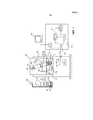
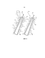
Маммографическое устройство МА содержит основание PD, на котором установлен источник XR рентгеновского излучения. Источник рентгеновского излучения может вращаться вокруг своей фокальной точки FSP. На основании PD установлена вращающаяся портальная рама с вращающейся полой рамой AR. Рама AR может вращаться вокруг фокальной точки FSP. Рама содержит две или больше интерференционные решетки (решетку G0 источника, и π-фазовую решетку G1 и/или решетку G2 анализатора), которые в совокупности позволяют формировать фазовое изображение, как будет пояснено ниже более подробно. G1 может также быть π/2-фазовой решеткой или другой соответствующей фазовой решеткой. Даже возможно, хотя и не предпочтительно, вместо фазовой решетки G1 использовать решетку поглотителя, что является предпочтительным вариантом осуществления при медицинских применениях, но версия с поглотителем для G1 может требоваться в немедицинских контекстах.The mammography device MA comprises a PD base on which an XR source of X-ray radiation is mounted. The x-ray source can rotate around its focal point FSP. A rotating gantry frame with a rotating hollow AR frame is mounted on the PD base. The AR frame can rotate around the focal point of the FSP. The frame contains two or more interference gratings (source grating G0, and π-phase grating G1 and / or analyzer grating G2), which together make it possible to form a phase image, as will be explained in more detail below. G1 may also be a π / 2 phase grating or other appropriate phase grating. It is even possible, although not preferable, to use an absorber array instead of the G1 phase grating, which is the preferred embodiment for medical applications, but an absorber version for G1 may be required in non-medical contexts.
На нижнем конце рамы AR устанавливается плата D детектора с чувствительной к излучению поверхностью для обнаружения излучения, излучаемого источником XR. Нижняя часть рамы также содержит крепление самих решеток GM, установленных сверху платы детектора. Крепление удерживает одну или две (предпочтительно, две) решетки G1, G2, с решеткой G1 над решеткой G2, и обе над платой детектора, в частности, обе решетки монтируются над чувствительной к излучению поверхностью платы D детектора. Решетка G0 источника располагается на верхнем конце рамы в выходном окне источника XR рентгеновского излучения. Также в одном из вариантов осуществления содержится и установлено на раме многоколлиматорное устройство, предпочтительно, предколлиматор PRC и постколлиматор PSC. Постколлиматор предназначен для удаления рассеяния, но этот компонент может не содержаться в конкретном варианте осуществления, поскольку решетка G2 действует аналогично для удаления рассеяния.At the lower end of the frame AR, a detector board D is mounted with a radiation-sensitive surface for detecting radiation emitted by the XR source. The lower part of the frame also contains the fastening of the GM gratings themselves, mounted on top of the detector board. The mount holds one or two (preferably two) gratings G1, G2, with grating G1 above grating G2, and both above the detector board, in particular, both gratings are mounted above the radiation-sensitive surface of the detector board D. The source grating G0 is located at the upper end of the frame in the output window of the XR source. Also, in one embodiment, a multi-collimator device is contained and mounted on the frame, preferably a PRC pre-collimator and a PSC post-collimator. The post-collimator is designed to remove scattering, but this component may not be contained in a particular embodiment, since the lattice G2 acts similarly to remove scattering.
Имеется область исследования, определяемая как углубление в корпусе маммографического устройства МА для помещения в него примерного изображаемого объекта, например, груди BR пациентки. Часть корпуса маммографического устройства MA определяет корпус детектора, верхняя поверхность которого служит опорой BS для груди, на которую помещается грудь BR пациентки во время сеанса визуализации, при этом опора груди таким образом ограничивает область исследования снизу. Имеется также пластина CP сжатия или лопатка, которая может совершить возвратно-поступательное движение вверх и вниз, чтобы сжимать грудь при ее размещении на опоре для груди.There is a research area, defined as a recess in the housing of the mammography device MA for placing an approximate imaged object, for example, the patient’s chest, in it. A part of the body of the mammography device MA defines a detector body, the upper surface of which serves as a BS support for the chest, on which the patient’s breast BR is placed during the imaging session, while the breast support thus limits the study area from below. There is also a compression plate CP or scapula, which can reciprocate up and down to compress the chest when it is placed on the chest support.
В дополнение к тому, что рама вращается, как описано выше, вся портальная рама также может вращаться вокруг центра вращения примерно на высоте опоры для груди. Вся портальная рама может, таким образом, наклоняться, чтобы изменять угол подхода для выборочной визуализации в различных проекциях, например, проекции CC (краниокаудальная) (вертикальное положение, на 12 часов) или проекции MLO (медио-латеральная наклонная), в положении приблизительно на 2 часа.In addition to rotating the frame as described above, the entire portal frame can also rotate around the center of rotation at about the height of the chest support. The entire portal frame can thus be tilted to change the angle of approach for selective visualization in various projections, for example, CC projection (craniocaudal) (vertical position, 12 hours) or MLO projection (medio-lateral inclined), in a position of approximately 2 hours.
Излучение от источника XR поступает на раму через выходное окно и затем проходит через раму к детектору. При ее прохождении волна излучения взаимодействует с первой решеткой G0, также называемый решеткой G0 источника, чтобы обеспечить когерентность.The radiation from the XR source enters the frame through the output window and then passes through the frame to the detector. As it travels, the radiation wave interacts with the first lattice G0, also called the source lattice G0, to ensure coherence.
Короче говоря, поток излучения проходит следующим образом: волна излучения коллимируется одним или двумя коллиматорами, затем взаимодействует с грудью BR, если она присутствует в области исследования, после этого взаимодействует с двумя решетками G1, G2 и затем падает на плату D детектора, где должна обнаруживаться.In short, the radiation flux proceeds as follows: the radiation wave is collimated by one or two collimators, then interacts with the breast BR, if it is present in the study area, then interacts with two gratings G1, G2 and then falls onto the detector board D, where it should be detected .
Маммографическое устройство МА выполнено с возможностью работы в двух основных режимах: в режиме контрольного сканирования или в режиме сканирования объекта. В режиме сканирования объекта, который является обычным режимом работы, грудь BR пациентки или другой образец размещается в области исследования. В режиме контрольного сканирования никакой объект или грудь не присутствует в области исследования. При сканировании объекта получают показания детектора, которые могут быть поданы на реконструктор RECON для вычисления фазоконтрастного проекционного изображения (и, при необходимости, (традиционного) изображения с контрастом по поглощению и/или изображения с контрастом по малому рассеиванию («темное поле»)) при операции получения фазы. Для работы по получению фазы необходим определенный параметр или данные калибровки, в частности, но не только, конкретные характеристики пикселей. Данные калибровки вычисляются модулем CAL калибровки модуля по показаниям детектора, полученным во время контрольного сканирования. Работа модуля CAL калибратора и модуля RECON реконструктора будет объяснена ниже более подробно со ссылкой на фиг. 6. Оба модуля предназначены для работы на рабочей станции WS.The mammography device MA is configured to operate in two main modes: in the control scan mode or in the object scan mode. In object scan mode, which is the normal mode of operation, the patient’s chest BR or other sample is placed in the study area. In the control scan mode, no object or chest is present in the study area. When scanning an object, detector readings are obtained, which can be fed to the RECON reconstructor to calculate a phase-contrast projection image (and, if necessary, a (traditional) image with absorption contrast and / or image with low dispersion contrast (“dark field”)) when phase acquisition operations. To work on obtaining the phase, a certain parameter or calibration data is required, in particular, but not only, the specific characteristics of the pixels. Calibration data is calculated by the CAL module of the module calibration according to the detector readings obtained during the control scan. The operation of the calibrator CAL module and the reconstructor RECON module will be explained in more detail below with reference to FIG. 6. Both modules are designed to work on the WS workstation.
Во время сканирования объекта или контрольного сканирования нижняя часть рамы (и с ней плата детектора и крепление решетки GM) механизирована, чтобы переместить детектор в корпусе под опору BS для груди. На левом краю фиг. 1 показана рама AR, наклоненная вбок, с ее компонентами, зависящими от ее положения и смонтированными в ней или на ней. В одном из режимов - сканирования объекта или контрольного сканирования - рама перемещается синхронно с вращением источника рентгеновского излучения вокруг ее фокальной точки FSP, так что плата детектора вместе с решетками G1 и G2 следуют по траектории SP сканера под грудью BR, если она присутствует. Обычно траектория сканирования представляет собой дугу, как показано на фиг. 1.During object scanning or control scanning, the lower part of the frame (and with it the detector board and the mount of the GM grating) are mechanized to move the detector in the housing under the BS support for the chest. On the left edge of FIG. 1 shows an AR frame tilted laterally, with its components depending on its position and mounted in or on it. In one of the modes - object scanning or control scanning - the frame moves synchronously with the rotation of the x-ray source around its focal point FSP, so that the detector board along with the gratings G1 and G2 follow the path of the scanner SP under the chest BR, if present. Typically, the scan path is an arc, as shown in FIG. one.
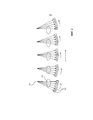
В одном из вариантов осуществления маммографическое устройство МА является устройством с одиночным или многочисленными срезами. Другими словами, чувствительная к излучению поверхность платы D детектора формируется одиночной или, вообще говоря, многочисленными (например, 8) строками полупроводникового детектора, осажденные на основание подложки, полученными посредством фотолитографии или другой подходящей технологии изготовления детектора. В центральной фронтальной вертикальной проекции, показанной на фиг. 1, эти строки DL детектора или дорожки уходят в плоскость бумаги, расположенную по бокам. Каждая строка детектора образуется линейной последовательностью пикселей детектора. Благодаря наличию устройства предколлиматора и постколлиматора, рентгеновский луч, по существу, расщепляется на множество минивеерных пучков, причем каждый веерный пучок излучается в какой-то один момент точно на одной из соответствующих строк детектора, а именно, той, которая оказывается проходящей через упомянутый веерный пучок во время движения детектора. Говоря иначе, строки детектора подвергаются облучению соответствующим минивеерным пучком, когда каждый минивверный пучок изменяет свое направление при сканировании. При прохождении вдоль траектории сканирования каждая строка детектора будет создавать соответствующие считывания в различных местах траектории. Другими словами, в отличие от двумерных сканеров, у которых все поле зрения получают в одном единственном снимке, в настоящей мультисрезной системе после завершения движения сканирования, последующие считывания детекторов во время сканирования могут использоваться для составления единого двумерного изображения поля зрения. На фиг. 2 схематично показана присущая избыточность (которая равна количеству строк детектора, имеющему порядок 20 строк в одном из вариантов осуществления) при подходе с мультисрезным сканированием. Строки детектора (пронумерованные как 1-5), проходят в плоскость бумаги, поперечную направлению сканирования. « считывания» в контексте настоящего документа означают данные, собранные пикселями вдоль заданной строки детектора, когда упомянутая строка детектора находится в заданном положении l на траектории сканирования. Говоря по-другому, считывания являются данными для каждого положения строки детектора.In one embodiment, the mammography device MA is a device with single or multiple slices. In other words, the radiation-sensitive surface of the detector board D is formed by a single or, generally speaking, by multiple (e.g. 8) rows of a semiconductor detector deposited on a substrate base obtained by photolithography or other suitable detector manufacturing technology. In the central front elevation shown in FIG. 1, these lines of the DL detector or track extend into a paper plane located on the sides. Each line of the detector is formed by a linear sequence of detector pixels. Due to the presence of a pre-collimator and post-collimator device, the x-ray beam is essentially split into many mini-fan beams, with each fan beam being radiated at one point exactly on one of the corresponding detector lines, namely, one that passes through the fan beam while the detector is moving. In other words, the detector lines are irradiated with a corresponding mini-fan beam when each mini-beam beam changes its direction during scanning. When passing along the scanning path, each line of the detector will create corresponding readings at different places on the path. In other words, unlike two-dimensional scanners, in which the entire field of view is obtained in one single image, in a real multislice system after the scanning movement is completed, subsequent readings of the detectors during scanning can be used to compose a single two-dimensional image of the field of view. In FIG. 2 schematically shows the inherent redundancy (which is equal to the number of detector lines having an order of 20 lines in one embodiment) in a multi-shear approach. Detector lines (numbered 1-5) extend into the paper plane transverse to the scanning direction. “Readings” in the context of this document means data collected by pixels along a given line of the detector when said line of the detector is in a predetermined position l on the scanning path. In other words, readings are data for each position of the detector line.
Локальное положение каждого пикселя или строки может указываться двумя «координатами», индексом столбца или строки и индексом пикселя. Поскольку ширина пикселя, расстояние между пикселями и расстояние между строками известны, то поэтому известно положение платы детектора в любой момент времени на его траектории SP, каждое считывание детектора (которое является пиксельной реакцией), может быть «пространственно отмечено» устройством слежения (не показано), поэтому каждое считывание детектора может быть связано с конкретным положением фиксированного геометрического луча, который может рассматриваться как проходящий от фокальной точки FSP через область исследования к плате D детектора. Существует множество таких геометрических лучей и к каждой точке в области исследования существует такой геометрический луч, который проходит через упомянутую точку, и множество лучей формируют конус с фокальной точкой FP в качестве вершины. Один такой геометрический луч показан на фиг. 2 полужирной линией. Пространственные отметки, связанные с показаниями, позволяют разрешить эту избыточность, как будет объяснено более подробно на фиг. 6 при объяснении работы реконструктора RECON.The local position of each pixel or row can be indicated by two “coordinates”, the column or row index and the pixel index. Since the width of the pixel, the distance between the pixels and the distance between the lines are known, the position of the detector board at any time on its path SP is known, each reading of the detector (which is a pixel response) can be “spatially marked” by a tracking device (not shown) Therefore, each reading of the detector can be associated with a specific position of a fixed geometric beam, which can be considered as passing from the focal point FSP through the study area to the e D detector. There are many such geometric rays, and for every point in the study area there is such a geometric ray that passes through the mentioned point, and many rays form a cone with the focal point FP as a vertex. One such geometric beam is shown in FIG. 2 bold line. The spatial elevations associated with the readings allow this redundancy to be resolved, as will be explained in more detail in FIG. 6 when explaining the operation of the RECON reconstructor.
Настоящее маммографическое устройство использует фазоконтрастную визуализацию, другими словами, контраст изображения, который создается упомянутым устройством визуализации, основан не исключительно на поглощении, как в случае традиционных рентгеновских систем, а основан также на контрасте, получаемом в результате фазовых сдвигов, которые испытывает фронт волны излучения, когда взаимодействует с веществом в груди. Фазовые сдвиги или искажения волны вызываются локально различным рефрактивным поведением отображаемого вещества.A real mammography device uses phase contrast imaging, in other words, the image contrast that is created by the imaging device mentioned above is not based solely on absorption, as is the case with traditional X-ray systems, but also based on the contrast resulting from phase shifts experienced by the radiation wave front, when interacting with a substance in the chest. Phase shifts or wave distortions are caused by locally different refractive behavior of the imaged substance.
Однако, фазовые сдвиги сами по себе не могут обнаруживаться детектором из-за отсутствию достаточной пространственной разрешающей способности. Вместо этого, фазовые сдвиги получают опосредованно, используя интерферометрические решетки для выборки пространственной картины, картины муарового изображения, то есть той, которая может обнаруживаться после соответствующей настройки вдоль строк детектора. Муаровые картины возникают, когда периодичность интерференционных полос немного и контролируемо отличается от периодичности структур решетки G2 анализатора. Этот подход предложен A. Momose и другими в "High-Speed X-ray phase imaging and X-ray phase tomography with Talbot interferometer and white synchrotron radiation" в Optics Express, том 17, № 15, стр. 12540, (2009). Во-первых, в зависимости от средней длины волны излучения источником XR и должным образом выбранных соответствующих периодичностей p0, p1, p2 решеток G0-G2, коллиматоры и решетки тщательно настраиваются относительно строк детектора на требуемое расстояние Тэлбота желаемого порядка, выравнивая ориентацию и расстояние. См., например, T. Donath и др. в "Inverse geometry for grating-based x-ray phase-contrast imaging", J. Appl. Phys. 106, 054703 (2009). В этот момент, внимательно перестраивая эту настройку Тэлбота, например, варьируя расстояние между решеткой G0 источника и π-фазной решеткой G1 (или π/2-фазной решеткой) эталонная муаровая картина возникает вдоль строк детектора во время контрольного сканирования. То, как обнаруживается эта эталонная муаровая картина, зависит от локальных характеристик различных пикселей детектора, как упомянуто ранее в связи с данными калибровки. Затем предложение состоит в том, чтобы введение объекта BR при сканировании объекта создавало возмущение этой муаровой картины. Возмущение представляется как фазовый сдвиг эталонной муаровой картины и этот фазовый сдвиг муаровой картины, как известно, связывается с локальным градиентом фазового сдвига, который испытывает волна, проходя через объект. Таким образом, необходимо знать фазу («эталонную фазу») муаровой картины, чтобы иметь возможность выполнить получение фазы. Определение упомянутого эталона муаровой фазы является частью задачи калибровки, в общем описанной выше.However, phase shifts alone cannot be detected by the detector due to the lack of sufficient spatial resolution. Instead, phase shifts are obtained indirectly, using interferometric gratings to sample a spatial picture, a moire pattern, that is, one that can be detected after appropriate adjustment along the lines of the detector. Moire patterns arise when the frequency of interference fringes is slightly and controllably different from the periodicity of lattice structures G2 of the analyzer. This approach was proposed by A. Momose and others in "High-Speed X-ray phase imaging and X-ray phase tomography with Talbot interferometer and white synchrotron radiation" in Optics Express, Volume 17, No. 15, p. 12540, (2009). Firstly, depending on the average wavelength of the radiation from the XR source and appropriately selected corresponding periodicities p0, p1, p2 of the G0-G2 gratings, the collimators and gratings are carefully tuned relative to the detector lines to the required Talbot distance of the desired order, aligning orientation and distance. See, for example, T. Donath et al. In "Inverse geometry for grating-based x-ray phase-contrast imaging", J. Appl. Phys. 106, 054703 (2009). At this point, carefully reconfiguring this Talbot setting, for example, by varying the distance between the source grating G0 and the π-phase grating G1 (or π / 2-phase grating), the reference moire pattern appears along the detector lines during the control scan. How this reference moire pattern is detected depends on the local characteristics of the various pixels of the detector, as mentioned earlier in connection with the calibration data. Then the proposal is that the introduction of the BR object when scanning the object creates a disturbance of this moire pattern. The perturbation is represented as a phase shift of the reference moire pattern and this phase shift of the moire pattern, as is known, is associated with the local gradient of the phase shift that the wave experiences as it passes through the object. Thus, it is necessary to know the phase ("reference phase") of the moire pattern in order to be able to obtain the phase. The determination of the moiré phase standard mentioned is part of the calibration task generally described above.
В предшествующих подходах к фазоконтрастной визуализации использовалась фиксированная интерферометрическая настройка, при которой для целей получения фазы одна из решеток двигалась относительно другой, чтобы сделать выборку интерференционной картины посредством «ступенчатого изменения фазы». См., например, T. Weitkamp и др. в "Optics Express", том 13, №16, стр. 6296-6304 (2005) Однако при настоящем подходе такое ступенчатое изменение фазы не требуется. Вместо этого операция получения фазы основана на сканирующем движении (вместе с движением решеток), которое используется здесь для анализа интерференционных полос муаровой картины, зарегистрированной детектором во время его движения для формирования желаемой фазоконтрастной информации (и попутно также быть полезна для визуализации на основе поглощения или визуализации в темном поле). Таким образом, движение детектора служит нескольким функциям: во-первых, оно позволяет получать полное поле зрения, что было первоначальной целью, и, во-вторых, движение используется для целей получения фазы.In previous approaches to phase contrast imaging, a fixed interferometric adjustment was used, in which, for the purpose of obtaining the phase, one of the gratings moved relative to the other in order to sample the interference pattern by means of a “stepwise phase change”. See, for example, T. Weitkamp et al. In Optics Express, Volume 13, No. 16, pp. 6296-6304 (2005) However, with the present approach, such a stepwise phase change is not required. Instead, the phase acquisition operation is based on the scanning movement (together with the movement of the gratings), which is used here to analyze the interference fringes of the moire pattern recorded by the detector during its movement to form the desired phase-contrast information (and also be useful in the process of visualization based on absorption or visualization in a dark field). Thus, the motion of the detector serves several functions: firstly, it allows you to get the full field of view, which was the original goal, and secondly, the motion is used for the purpose of obtaining the phase.
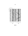
Однако избыточность в считываниях добавляет уровень сложности. Из-за сканирующего движения муаровая картина не только распределяется в пространстве вдоль строки детектора, но также распределяется во времени по различным считываниям детектора в различных положениях вдоль траектории. Прежде чем обратиться к модели CAL калибровки более подробно, теперь со ссылкой на фиг. 2 и фиг. 3 должны быть более подробно рассмотрены определенные характеристики считываний детектора при контрольном сканировании. Предположим на мгновение, что на фиг. 2 никакой объект не присутствует, что имеет место при контрольном сканировании. По мере того, как детектор движется вперед по своей траектории сканирования, определенная строка детектора, скажем, строка 5 на фиг. 2, будет принимать излучение от рентгеновского источника и эталонная муаровая картина будет возникать вдоль пикселей pxk упомянутой строки 5 детектора (строка детектора, показанная на фиг. 2, проходит в плоскость бумаги). Можно затем ожидать, что муаровые картины в каждый момент считывания могли бы быть одинаковыми. В конце концов, можно себе представить, что излучение проходит просто через воздух, который должен быть одинаковым для любой строки детектора, независимо от ее положения на трассе сканирования. Хотя, на самом деле, дело обстоит не так. Вместо этого, заявитель наблюдал, что муаровая картина, наблюдаемая одной и той же строкой детектора во время движения сканирования, не является одинаковой. Это показано на фиг. 3.However, redundancy in readings adds a level of complexity. Due to the scanning motion, the moiré pattern is not only distributed in space along the detector line, but also distributed in time over various readings of the detector at different positions along the path. Before turning to the CAL calibration model in more detail, now with reference to FIG. 2 and FIG. 3, certain characteristics of the readings of the detector during control scanning should be considered in more detail. Assume for a moment that in FIG. 2 no object is present, which is the case with control scanning. As the detector moves forward along its scanning path, a specific line of the detector, say
Левая часть на фиг. 3a показывает время 1 считывания относительно результатов измерений строки детектора, где k указывает положения пикселей на определенной одиночной строке. В различные моменты считывания существует дрейф, который можно видеть как темные и светлые полосы, проходящие на чертеже под наклоном, определяемым множеством считываний согласно фиг. 3. На правой стороне на фиг. 3b показан дрейф той же самой ширины во время сканирования объекта и замечательным является тот факт, что дрейф хорошо повторяется для контрольного сканирования и для сканирования объекта. Приблизительно на половине пути вдоль направления 1 считывания можно видеть «перегиб», который указывает момент, когда рама AR сканирования перешла через горизонтальное положение. Заявители заметили, что этот дрейф муара может быть обусловлен механическим несовершенством жесткости сканирующей рамы AR. Другими словами, рама AR и, следовательно, крепление GM решеток, расположенное на ней, слегка деформируются во время движения сканирующей рамы в связи с недостаточной жесткостью. Связанные с показаниями электроники широкие, темные полосы, проходящие вертикально, которые в одном из вариантов осуществления накладываются на строки детектора, так что там не может быть обнаружено никакое излучение. Например, задние полосы отмечают местоположение ASIC или другого электронного компонента. Однако, присутствие этих черных полос является только примером, поскольку в альтернативных вариантах осуществления компонент электроники считывания не накладывается на строки детектора.The left part in FIG. 3a shows the read time 1 with respect to the measurement results of the detector row, where k indicates the positions of the pixels on a particular single row. At various points in the reading, there is a drift that can be seen as dark and light stripes passing in the drawing at an angle determined by the plurality of readings according to FIG. 3. On the right side in FIG. 3b shows a drift of the same width during scanning of an object, and the remarkable fact is that the drift is well repeated for a reference scan and for scanning an object. About halfway along the read direction 1, a “bend” can be seen which indicates the moment when the scanning frame AR has moved through a horizontal position. Applicants have observed that this moire drift may be due to a mechanical imperfection in the rigidity of the AR scanning frame. In other words, the AR frame and, consequently, the fastening GM of the gratings located on it, are slightly deformed during the movement of the scanning frame due to insufficient rigidity. Associated with the readings of the electronics are wide, dark stripes extending vertically, which in one embodiment are superimposed on the lines of the detector, so that no radiation can be detected there. For example, back bars mark the location of an ASIC or other electronic component. However, the presence of these black bars is only an example, since in alternative embodiments, the readout electronics component does not overlap the detector lines.
Предлагается здесь сформулировать функцию модели сигнала, учитывающую упомянутый дрейф муаровой картины. Более конкретно, предлагается не только использовать конкретные количества детектора, которые обычно желательно определить при калибровке с контрольным сканированием, но также усилить эту модель введением в нее неизвестных дрейфа муаровой картины и, таким образом, увеличить объем переменной, чтобы достигнуть более стабильной оценки. Последующее моделирование является одним и тем же для каждой из строк детектора, поэтому мы далее в интересах компактности системы обозначений пропустим индекс строки. Обозначим измеренные интенсивности одной строки детектора во время сканирования как Ikl, где k является индексом столбца детектора и l - индекс считывания. Сначала опишем простую версию идеи, чтобы проиллюстрировать базовую концепцию. В этой упрощенной версии муаровая картина, измеренная посредством Ikl, моделируется, чтобы следовать функции сигнала:It is proposed here to formulate the function of the signal model, taking into account the mentioned drift of the moire pattern. More specifically, it is proposed not only to use specific quantities of the detector, which is usually desirable to determine during calibration with a control scan, but also to strengthen this model by introducing unknown moiré drifts into it and, thus, increase the volume of the variable in order to achieve a more stable estimate. The subsequent modeling is the same for each of the detector lines; therefore, in the interest of compact notation, we will skip the row index. We denote the measured intensities of one row of the detector during scanning as I kl , where k is the index of the detector column and l is the read index. First, we describe a simple version of the idea to illustrate the basic concept. In this simplified version, the moire pattern, measured by I kl , is modeled to follow the signal function:
Ikl=Ak(1+Vkcos(κk+ϕl)) (1)I kl = A k (1 + V k cos (κk + ϕ l )) (1)
Функция модели сигнала согласно (1) содержит два параметра, а именно, Ak и Vk, которые являются характеристикой детектора и локальными свойствами решеток. Параметр Ak относится к произведению входящей интенсивности и чувствительности пикселя k детектора, а параметр Vk относится к локальной видимости интерференционной полосы для пикселя k детектора. Поскольку эти два параметра являются конкретными параметрами детектора и решетки, они не меняются при изменении индекса l считывания, так как вместо этого они зависят только от положения k пикселя. Изменения картины интерференционной полосы во время считывания полностью зависят от простого фазового сдвига интерференционной картины, представленного специфичными для считывания фазами ϕ l. Наконец, модель содержит также глобальный параметр κ, связанный с пространственной частотой интерференционных муаровых полос, обнаруживаемых вдоль строк детектора. В системе без какого-либо дрейфа муаровой картины все фазы ϕ l должны быть одинаковы. Обеспечивая охватывание дрейфом нескольких периодов муаровой картины для каждого пикселя детектора во время сканирования, может быть получена стабильная оценка Ak и Vk.The signal model function according to (1) contains two parameters, namely, A k and V k , which are the characteristic of the detector and local properties of the gratings. The parameter A k refers to the product of the incoming intensity and sensitivity of the detector pixel k, and the parameter V k refers to the local visibility of the interference band for the detector pixel k. Since these two parameters are specific parameters of the detector and the grating, they do not change when the read index l changes, since instead they depend only on the position of the k pixel. Changes in the pattern of the interference band during reading are completely dependent on the simple phase shift of the interference pattern represented by readout-specific phases ϕ l . Finally, the model also contains the global parameter κ associated with the spatial frequency of the interference moire bands detected along the detector lines. In a system without any drift of the moire pattern, all phases ϕ l must be the same. By providing a drift coverage of several periods of the moire pattern for each detector pixel during scanning, a stable estimate of A k and V k can be obtained.
Однако, как можно видеть, величина дрейфа находится более или менее в зависимости от мгновенной конфигурации рамы AR устройства визуализации и определенной заданной жесткости, которая обычно не управляется разработчиком системы. Здесь предлагается это изменить и снабдить маммографическое устройство МА механическим средством, таким как элемент жесткости RGD, чтобы иметь возможность управлять жесткостью, в частности, рамы AR сканера и всех креплений GM решеток, посредством соответствующего механического действия.However, as you can see, the magnitude of the drift is more or less dependent on the instantaneous configuration of the AR frame of the imaging device and a certain predetermined stiffness, which is usually not controlled by the system designer. It is proposed here to change this and equip the mammography device MA with mechanical means, such as the stiffener RGD, in order to be able to control the stiffness of, in particular, the AR frame of the scanner and all the fastenings GM of the gratings, by means of an appropriate mechanical action.
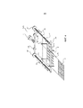
На фиг. 4 показано устройство для непосредственного управления жесткостью креплений GM решеток, расположенных в раме AR сканера. На фиг. 4 показан вид в перспективе крепления GM решеток, которое в этом варианте осуществления является рамой (в одном из вариантов осуществления изготовленной из стали), установленной на плате D детектора. В примерном варианте осуществления, показанном на фиг. 4, четыре строки DL детектора показаны как осажденные на плату D детектора. В общем плане, устройство элемента жесткости RGD может представляться как устройство с ходовым винтом. Имеется набор захватов JW, которые охватывают каркас креплений GM решеток с двух сторон. На одном из концов этих двух захватов резьбовой вал TS проходит через соответствующие отверстия в захватах и жестко соединяется с ними. Направляющая гайка NT устанавливается на соответствующих концах резьбовых валов и может продвигаться вперед вдоль вала в направлении соответствующих концов захватов JW под действием соответствующего зубчатого устройства GR, которое действует, чтобы сцеплять упомянутые гайки с колесом T с накаткой, которое вращается пользователем. В процессе работы пользователь вращает колесо T с накаткой и, таким образом, осуществляет продвижение вперед гаек NT зубчатого устройства вдоль их соответствующего резьбового вала, чтобы принудительно заставить каждую из них войти в зацепление с соответствующими захватами JW. Это позволяет пользователю прикладывать силу к каркасу GM и существенно его сжимать, изменяя, таким образом, жесткость крепления GM решеток. В соответствии с одним из вариантов осуществления, имеется храповый механизм, вставленный между зубчатым сцеплением и колесом T с накаткой для обеспечения того, чтобы сила прикладывалась к каркасу GM только дискретными ступенями и не могла изменяться непрерывно. Это обеспечивает более высокую повторяемость конкретной муаровой картины, которая связывается с определенным приложением силы. Также, как показано на фиг. 4, существуют устройства TR слежения сформированные в каркасе GM, в который решетки G1 или G2 (на фиг. 4 для простоты представления показана только одна решетка G1), устанавливаются с возможностью скольжения, мало чем отличающегося от скольжения в диапроекторе. Однако, следует понимать, что элемент жесткости, который непосредственно воздействует на каркас GM с креплением решеток, может принимать самые разные формы и на фиг. 4 показан только один из вариантов осуществления. Хотя вариант осуществления показанный на фиг. 4, предназначен для ручной работы, моторизованная версия также предусматривается и имеет контроллер, который воздействует или изменяет жесткость в ответ на входное воздействие. Также на фиг. 4 обе гайки NT двигаются синхронно под управлением винта Т с накаткой. Это всего лишь один вариант осуществления, однако, в качестве других вариантов осуществления предусматриваются варианты, в которых каждая гайка может приводиться в действие независимо от другой, которые применются как в ручной, так и в моторизованной версиях. Например, также предусмотрено микрометрическое устройство, в котором устройство типа микрометра выполнено таким образом, что каркас GM приходит в положение между двумя зажимами. Действие наконечника микрометра продвигает вперед шпиндель и каркас GM решеток входит в зацепление между зажимами, чтобы приложить к нему усилие. Опять, соответствующий механизм храпового типа может быть установлен так, чтобы обеспечивать, что приложение силы ограничивается дискретными ступенями с измеренной и градуированной силой.In FIG. 4 shows a device for directly controlling the rigidity of the mounts GM gratings located in the frame of the AR scanner. In FIG. 4 shows a perspective view of the fastening of GM gratings, which in this embodiment is a frame (in one embodiment made of steel) mounted on the detector board D. In the exemplary embodiment shown in FIG. 4, four lines of the DL detector are shown as being deposited on the detector board D. In General terms, the device of the stiffener RGD can be represented as a device with a lead screw. There is a set of JW grippers that cover the GM grid mount frame on both sides. At one end of these two grips, the threaded shaft TS passes through the corresponding holes in the grips and is rigidly connected to them. The guide nut NT is mounted on the respective ends of the threaded shafts and can advance along the shaft towards the respective ends of the jaws JW under the action of the corresponding gear device GR, which acts to engage the said nuts with the knurled wheel T, which is rotated by the user. In the process, the user rotates the knurled wheel T and thus advances the gear nuts NT of the gear along their corresponding threaded shaft in order to force each of them to engage with the respective jaws JW. This allows the user to apply force to the GM carcass and compress it substantially, thus changing the rigidity of the fastening of the GM gratings. According to one embodiment, there is a ratchet mechanism inserted between the gear clutch and the knurled wheel T to ensure that the force applied to the frame GM only in discrete steps and cannot change continuously. This provides a higher repeatability of a particular moire pattern, which is associated with a specific application of force. Also, as shown in FIG. 4, there are tracking devices TR formed in the frame GM, in which the gratings G1 or G2 (in Fig. 4, for simplicity of presentation, only one grating G1 is shown) are mounted with the possibility of sliding, not much different from sliding in a slide projector. However, it should be understood that the stiffening element, which directly affects the frame GM with the fastening of the gratings, can take many different forms and in FIG. 4 shows only one embodiment. Although the embodiment shown in FIG. 4 is intended for manual operation, a motorized version is also provided and has a controller that acts or changes stiffness in response to an input effect. Also in FIG. 4 both nuts NT move synchronously under the control of the thumb screw T. This is just one implementation option, however, as other embodiments, options are provided in which each nut can be actuated independently of the other, which are used in both manual and motorized versions. For example, a micrometric device is also provided in which a micrometer-type device is designed such that the frame GM comes into position between two clamps. The action of the tip of the micrometer propels the spindle forward and the frame of the gratings GM engages between the clamps to exert force on it. Again, an appropriate ratchet-type mechanism can be installed to ensure that the application of force is limited to discrete steps with measured and graduated force.
На фиг. 5 показан альтернативный вариант осуществления, который может использоваться вместо или в дополнение к варианту осуществления, показанному на фиг. 4. На фиг. 5 элемент жесткости RGD воздействует на каркас крепления решеток косвенно за счет приводов BA, расположенных с любой из сторон рамы AR. Другими словами, на фиг. 5 элемент жесткости воздействует непосредственно на раму, чтобы изменять жесткость рамы.In FIG. 5 shows an alternative embodiment that can be used instead of or in addition to the embodiment shown in FIG. 4. In FIG. 5, the stiffening element RGD acts on the lattice mounting frame indirectly due to BA drives located on either side of the AR frame. In other words, in FIG. 5, the stiffening element acts directly on the frame to change the stiffness of the frame.
На фиг. 5а показаны приводы BA, например, стержневые элементы, расположенные в соответствующем количестве (один или более, в данном случае, три элемента показаны в качестве примера, но не для создания ограничения) попарно вдоль рамы AR. Под воздействием приводов BA сила прикладывается к раме AR в соответствующих местах, чтобы, таким образом, изменять общую жесткость рамы AR. Другие наборы приводов могут работать синхронно или могут также действовать независимо, таким образом, предоставляя более высокую степень заказной возможности изменения жесткости.In FIG. 5a shows actuators BA, for example, rod elements arranged in an appropriate amount (one or more, in this case, three elements are shown as an example, but not to create a limitation) in pairs along the frame AR. Under the influence of the BA actuators, a force is applied to the frame AR in the corresponding places in order to thereby change the overall rigidity of the frame AR. Other sets of drives can operate synchronously or can also act independently, thus providing a higher degree of custom stiffness variation.
В другом варианте осуществления используется биметаллическая фольга. Одна сторона упомянутой фольги прикрепляется с помощью сварки или клея к раме AR, одной из сторон, внутренней или внешней. Рама по существу «заворачивается» или обертывается упомянутой фольгой. Затем биметаллический металл нагревается до различных температур (перед сканированием, чтобы учесть определенную тепловую инерционность), чтобы затем увеличивать или уменьшать чувствительность рамы к изгибу за счет изменения гравитационных вращающих моментов во время сканирования.In another embodiment, a bimetallic foil is used. One side of said foil is attached by welding or glue to an AR frame, one of the sides, internal or external. The frame is essentially “wrapped” or wrapped with said foil. Then the bimetallic metal is heated to various temperatures (before scanning to take into account a certain thermal inertia), to then increase or decrease the sensitivity of the frame to bending due to changes in gravitational torques during scanning.
В одном из вариантов осуществления работа элемента жесткости происходит во время фактического движения сканирования в отличие от предрегулировок или пострегулировок сканирования, которые также предусматриваются. В одном из вариантов осуществления контроллер RGDC элемента жесткости управляет элементом жесткости RGD автоматически. Например, что наблюдалось ранее в связи с фиг. 2, величина фазового сдвига муаровой картины является индикатором жесткости или ее отсутствия. Считывания согласно фиг. 2 для определенной строки детектора могут быть введены в контроллер RGDC. Контроллер RGDC затем управляет приводами BA, чтобы динамически увеличивать/уменьшать жесткость в зависимости от обнаруженной величины дрейфа фазы муара в соответствии с показаниями детектора. Большое изменение повлечет за собой приложение большей силы, чтобы сохранить жесткость, тогда как в другом случае приложение силы может быть ослаблено. Контролер может таким образом работать в замкнутом контуре, чтобы увеличивать или уменьшшать силу для поддержания желательного смещения муаровой картины или обеспечивать, чтобы этот фазовый сдвиг оставался ниже определяемого пользователем порога.In one embodiment, the operation of the stiffener occurs during the actual movement of the scan, in contrast to the pre-adjustments or post-adjustments of the scan, which are also contemplated. In one embodiment, the stiffener element controller RGDC controls the stiffener element RGD automatically. For example, what was previously observed in connection with FIG. 2, the magnitude of the phase shift of the moire pattern is an indicator of stiffness or its absence. The readings of FIG. 2 for a specific detector line can be entered into the RGDC controller. The RGDC controller then controls the BA drives to dynamically increase / decrease stiffness depending on the detected moire drift value according to the detector. A large change will entail the application of more force to maintain rigidity, while in another case, the application of force can be weakened. The controller may thus operate in a closed loop to increase or decrease the force to maintain the desired moire pattern bias, or to ensure that this phase shift remains below a user-defined threshold.
В альтернативном варианте осуществления или в дополнение к контролю считываний, чтобы определить велчину силы (или теплоты, в зависимости от обстоятельств, для варианта осуществления с биметаллом), которая должна прикладываться, работа элемента жесткости может быть связана с определенными положениями платы детектора на траектории SP. Например, как наблюдалось ранее, при прохождении рамы AR через вертикальное положение существует изменение фазы муара. Это может быть моментом тогда, когда требуется большая жесткость. Работа контроллера RGDC может поэтому программироваться так, чтобы сила прикладывалась в ответ на положение рамы AR вдоль ее траектории SP, в частности, сила прикладывается, когда рама принимает вертикальное положение.In an alternative embodiment, or in addition to reading control, to determine the magnitude of the force (or heat, as the case may be, for the bimetal embodiment) to be applied, the operation of the stiffener may be associated with certain positions of the detector board on the SP path. For example, as previously observed, when the AR frame passes through a vertical position, there is a change in the moire phase. This can be the moment when more rigidity is required. The operation of the RGDC controller can therefore be programmed so that a force is applied in response to the position of the frame AR along its path SP, in particular, the force is applied when the frame takes a vertical position.
Кроме того, может быть полезным немного изменять уровень общего фазового сдвига интерференционной полосы между проекцией MLO, когда портальная рама находится под средним углом приблизительно 40%-50% от вертикали, и проекцией CC, когда портальная рама находится под средним углом вблизи вертикального направления. Управление сдвигом посредством изменения жесткости будет смещать раму или каркас GM, так как в противном случае будут возникать нежелательные эффекты, вызванные воздействием силы тяжести на различные компоненты, которые будут различными для различных угловых положений для других проекций.In addition, it may be useful to slightly vary the level of the overall phase shift of the interference band between the MLO projection when the portal frame is at an average angle of approximately 40% -50% of the vertical and the CC projection when the portal frame is at an average angle near the vertical direction. Controlling the shear by changing the stiffness will shift the GM frame or frame, since otherwise undesirable effects will occur due to the action of gravity on different components, which will be different for different angular positions for other projections.
В соответствии с одним из вариантов осуществления предусматривается, что соответствующие считывания во время работы элемента жесткости формируются для просмотра на экране, что позволяет пользователю напрямую следить за тем, как изменяется муаровая картина при изменении приложения силы. В одном из вариантов осуществления графическое представление дрейфа муаровой картины показано на фиг. 3 и может формироваться для просмотра на экране.In accordance with one embodiment, it is contemplated that appropriate readings during operation of the stiffener are generated for viewing on the screen, which allows the user to directly monitor how the moiré pattern changes as the application of force changes. In one embodiment, a graphical representation of the moire pattern drift is shown in FIG. 3 and may be configured for viewing on a screen.
Обратимся к процессу считывания детектором. В более общем плане, как будет обяснено ниже более подробно, данные калибровки получают при наличии считывания детектором во время контрольного сканирования, обработанных блоком CAL калибровки. Калибровочные данные затем подаются на реконструктор RECON, который затем работает, чтобы выполнить этап получения фазы для формирования, помимо прочего, фазоконтрастного изображения и/или изображения на основе поглощения и/или изображения на основе рассеяния.Let us turn to the reading process by the detector. More generally, as will be explained in more detail below, calibration data is obtained by reading by the detector during a proof scan processed by the CAL calibration unit. Calibration data is then supplied to the RECON reconstructor, which then works to perform the phase acquisition step to form, among other things, a phase-contrast image and / or image based on absorption and / or image based on scattering.
Обращаясь теперь к работе модуля CAL калибровки, ссылка будет делаться на блок-схему последовательности выполнения операций, показанную на фиг. 6. На этапе 605 жесткость рамы AR и/или крепления GM решеток регулируется до желаемой степени жесткости.Turning now to the operation of the CAL calibration module, reference will be made to the flowchart shown in FIG. 6. At 605, the rigidity of the frame AR and / or the attachment of the GM grilles is adjusted to the desired degree of rigidity.
На этапе 610 контрольное сканирование теперь выполняется с рамой, имеющей желаемую жесткость. Каждый пиксель реагирует, выдавая электрический сигнал, зависящий от интенсивности излучения, получаемой соответствующим пикселем в данный момент и/или в данном положении вдоль траектории сканирования. Набор этих электрических сигналов затем преобразуется аналогово-цифровым (A/D) преобразователем посредством блока DAS сбора данных в цифровую форму и затем передается калибратору CAL в качестве соответствующих считываний детектора. Было замечено, что для формирования муаровой картины требуется определенное минимальное количество пикселей на строку детектора. Было обнаружено, что для хорошей работы количество пикселей должно составлять приблизительно 200 или 250 пикселей (в частности, 256).At step 610, a control scan is now performed with the frame having the desired stiffness. Each pixel responds by producing an electrical signal depending on the radiation intensity received by the corresponding pixel at the moment and / or in a given position along the scanning path. The set of these electrical signals is then converted by an analog-to-digital (A / D) converter through a DAS data acquisition unit into digital form and then transmitted to the CAL calibrator as corresponding detector readings. It was noted that a certain minimum number of pixels per detector line is required to form a moire pattern. It was found that for good performance the number of pixels should be approximately 200 or 250 pixels (in particular 256).
Соответствующие считывания Ikl детектора затем на этапе 615 аппроксимируются к модели, соответствующей приведенному выше уравнению (1). Аппроксимация может быть достигнута при использовании метода наименьших квадратов или метода взвешенных наименьших квадратов или любого другого соответствующего метода численной аппроксимации кривой. Например, при подходе по методу наименьших квадратов уравнение (1) может быть переформулировано как объективная функция ![]()
![]()
![]()
![]()
Это достаточно серьезная проблема нелинейной аппроксимации с тремя неизвестными Ak, Vk,![]()
![]()
Оптимизация может быть выполнена в одном из вариантов осуществления в несколько этапов нестрогого метода итерационных координат, который разбивает большую проблему на несколько более мелких подпроблем, которые решаются легче. В частности, при введении объективной функции ![]()
![]()
![]()
![]()
Эта операция нелинейной аппроксимации с тремя неизвестными Ak, Vk, ![]()
![]()
Выходным результатом этапа S615 аппроксимации является тройка параметров калибровки для каждого пикселя k соответствующей строки детектора. Калибровочная тройка для каждого пикселя на данной строке детектора содержит два зависящих от пикселя параметра: i) входная интенсивность Ak, и ii) видимость Vk. Существует также независимый от пикселя параметр, а именно, локальная фаза ![]()
![]()
В альтернативном варианте осуществления вместо этого используется другая, более подробная функция модели сигнала. Функция модели, используемая в уравнении 1, является просто чисто синусоидальным вариантом муаровой интерференционной полосы. Если решетки интерферометра не являются совершенно плоскими, могут существовать отклонения от этой идеальной модели. Более сложные модели, возможно с эвристическими параметрами, могут использоваться для моделирования результатов измерений в такой ситуации. Одним конкретным набором дополнительных параметров, который был реализован, являются средние значения положений пикселей для конкретных пикселей в пределах строки детектора в следующем виде:In an alternative embodiment, another, more detailed function of the signal model is used instead. The model function used in equation 1 is simply a purely sinusoidal version of the moire interference band. If the arrays of the interferometer are not completely flat, deviations from this ideal model may exist. More complex models, possibly with heuristic parameters, can be used to model the measurement results in such a situation. One specific set of additional parameters that has been implemented are the average values of pixel positions for specific pixels within the detector line in the following form:
![]()
![]()
В основном, модель является усовершенствованием модели, соответствующей уравнению 1, которое учитывает отклонения от чисто синусоидальной формы, предполагая, что пиксели детектора перемещаются вдоль их соответствующей строки детектора на фиксированное значение Δk от номинального интервала между пикселями (который в одном варианте осуществления составляет порядка 50 микрон, но это лишь пример, не предназначенный для ограничения). Конечно, это только "интерпретация" параметра Δk, который не обязательно представляет истинную причину отклонения. Фактически, несовершенство решетки может приводить к фазовому сдвигу муаровой картины, который также может быть хорошо представлен параметром Δk. При использовании функции модели сигнала в соответствии с уравнением 4 вместо уравнения 4, происходит аппроксимация переменных, а именно, трех переменных Ak, Vk, ![]()
![]()
![]()
![]()
Когда посредством операции оптимизации параметры Ak, Vk, ![]()
![]()
![]()
![]()
На этапе 620a выполняется сканирование объекта. Снова передаются считывания детектора, но на этот раз на реконструктор RECON через переключатель SW.At step 620a, an object scan is performed. The detector readings are again transmitted, but this time to the RECON reconstructor via the SW switch.
Чтобы лучше понять работу этапа получения фазы, который должен выполняться на этапе 625, стоит заметить, что работа модуля CAL калибровки не была обременена избыточностью в отношении той же самой геометрической матрицы, как наблюдалось ранее. Как следует понимать, предыдущие вычисления до этапа S620a продолжаются по строкам детектора, где каждая тройка параметров калибровки назначается для каждого из пикселей k при каждом из считываний l. Этот контекст «построчной обработки» более не применим к этапу получения фазы. Вместо этого контекстом обработки для получения фазы являются все данные, принадлежащие одному и тому же геометрическому лучу. Именно поэтому, чтобы получить пиксель в фазоконтрастном изображении, которое должно быть реконструировано, будет необходимо собрать все эти результаты измерений детектора, которые вносят свой вклад в пиксель изображении, которое должно представлять накопленные фазовые сдвиги вдоль упомянутой геометрической траектории. Накопленные фазовые сдвиги затем формируют проекционную точку, которая служит в качестве контраста изображения. Эта операция сбора данных для каждого геометрического луча может быть выполнена посредством действия устройства захвата данных, которое оценивает «пространственные отметки» для каждого считывания и собирает пиксельные считывания в группы для каждой геометрической матрицы.In order to better understand the operation of the phase acquisition phase, which should be performed at
Получение фазы выполняется независимо для каждого геометрического луча. Обозначим количество измерений для заданного луча как n. Дополнительно, пиксели, вносящие свой вклад в этот геометрический луч, имеют параметры калибровки Ai, Vi и βi=κ(i+Δi)+ϕl или βi=κi+ϕl (в зависимости от того, использовалась ли модель 1a или 1), как было ранее определено на этапе калибровки. Фактические результаты измерений пикселей, полученные во время сканирования объекта, обозначаются как gi. Влияние объекта BR на результаты измерений моделируется тремя параметрами изображения В (затухание рентгеновского пучка), S (потеря видимости интерференционной картины за счет малого углового рассеивания, это также называют темным полем) и ϕ (фазовый сдвиг пучка за счет рефракции, которая (после соответствующего масштабирования) соответствует фактическому фазоконтрастному изображению, которое должно быть реконструировано. Другие параметры изображения для изображения на основе поглощения и темного поля могут потребоваться или не потребоваться при дополнительной обработке или отображении.The phase acquisition is performed independently for each geometric ray. We denote the number of measurements for a given ray as n. Additionally, the pixels contributing to this geometric ray have calibration parameters A i , V i and β i = κ (i + Δi) + ϕ l or β i = κi + ϕ l (depending on whether the model was used 1a or 1) as previously determined in the calibration step. Actual pixel measurements obtained during scanning of an object are indicated as g i . The influence of the BR object on the measurement results is modeled by three image parameters B (X-ray attenuation), S (loss of visibility of the interference pattern due to small angular scattering, this is also called a dark field) and ϕ (phase shift of the beam due to refraction, which (after appropriate scaling ) corresponds to the actual phase-contrast image to be reconstructed. Other image parameters for the image based on absorption and dark field may or may not be required ovatsya during further processing or display.
Эти параметры изображения B, S, ϕ для каждого геометрического луча (то есть узла решетки изображения) оценивают, минимизируя функцию стоимости:These image parameters B, S, ϕ for each geometric ray (i.e. the image lattice node) are estimated by minimizing the cost function:
![]()
![]()
Это нелинейная аппроксимация с тремя неизвестными, которая снова может быть найдена посредством нисходящего симплексного алгоритма или другого соответствующего алгоритма оптимизации, как объяснялось ранее в связи с этапом аппроксимации модуля CAL калибровки. Выходным результатом на этапе S620 для каждого геометрического луча является соответствующая точка изображения, которые совместно (взятые для всех геометрических лучей) определяют результирующие изображения на основе затухания, потери видимости и дифференциальной фазы.This is a non-linear approximation with three unknowns, which can again be found using a top-down simplex algorithm or other appropriate optimization algorithm, as explained earlier in connection with the approximation step of the CAL calibration module. The output in step S620 for each geometric ray is the corresponding image point, which together (taken for all geometric rays) determine the resulting images based on attenuation, loss of visibility and differential phase.
Затем на этапе S630 результирующие изображения на основе затухания и/или потери видимости и/или дифференциальной фазы выводятся и могут быть сформированы для отображения на мониторе MT или изображение может обрабатываться как-либо иначе.Then, in step S630, the resulting images based on the attenuation and / or loss of visibility and / or the differential phase are output and may be generated for display on the MT monitor or the image may be processed in some other way.
Существует также необязательный этап 620b коррекции артефактов, осуществляемый модулем CORR коррекции. Заявители в некоторых случаях наблюдали в реконструированном изображении определенные артефакты. Более конкретно, основная структура артефактов продолжает следовать муаровой картине. Источником этих артефактов является тот факт, что даже при расширенной модели сигнала, соответствующей уравнению (4), контрольное сканирование не моделируется с достаточной точностью. Чтобы бороться с этими артефактами дрейфа, здесь предлагается концепция аннулирования артефакта, как описано здесь далее. Дополнительно наблюдалось, что артефакты, сами по себе присутствующие в дифференциальном фазовом изображении, полученном, в частности, для расширенной модели согласно уравнению (4), хорошо воспроизводятся, если мы используем контрольное сканирование в качестве сканирования объекта. Другими словами, сами параметры калибровки обрабатываются на этапе S20b, как если бы они получены из сканирования «объекта», выполняя операцию получения фазы, аналогичную этапу S625. Другими словами, тройка параметров калибровки группируется устройством захвата в группы для каждого геометрического луча, как было объяснено ранее для этапа S625 «реального» получения фазы на основании данных сканирования объекта. Соответствующие изображения на основе поглощения, темного поля и фазового сдвига могут считаться соответствующими изображениями с коррекцией; такими изображениями являются изображение на основе поглощения с коррекцией, изображение на основе темного поля с коррекцией и фазоконтрастное изображение с коррекцией. Опять же эта операция обращения с контрольным сканированием как со сканированием объекта, выполняя операцию получения фазы для данных калибровки контрольного сканирования, весьма парадоксальна, поскольку калибровочные данные сами по себе обычно не предназначены для отображения и операция получения фазы обычно выполняется точно, чтобы получить изображения для отображения. Теперь, увидев, что мы можем воспроизводить некоторые артефакты с помощью этого дополнительного контрольного сканирования для процесса сканирования объекта, здесь предлагается передавать это изображение с коррекцией обратно на реконструктор изображения и аннулировать эти артефакты, вычитая это «чистое» изображение после коррекции артефактов из истинного изображения объекта, полученного во время получения фазы. Другими словами, изображение с коррекцией используется при выполнении операции получения фазы для данных изображения объекта. В одном из вариантов осуществления применение изображения с коррекцией соответствует ![]()
![]()
![]()
![]()
![]()
![]()
Чтобы избежать введения дополнительного шума из-за этапа аннулирования артефактов, изображение с артефактами несколько фильтруется фильтром нижних частот в направлении сканирования.To avoid introducing additional noise due to the artifact cancellation step, the image with artifacts is somewhat filtered by a low-pass filter in the scanning direction.
Влияние различных этапов обработки, то есть улучшенное моделирование интерференционной картины согласно уравнениям 1 и 1a и аннулирование артефактов на этапе 620b здесь было объяснено, используя только дифференциальные фазоконтрастные изображения. Для изображения с контрастом на основе затухания и изображения на основе видимости могут быть получены аналогичные улучшения.The effect of the various processing steps, that is, the improved modeling of the interference pattern according to equations 1 and 1a and the cancellation of artifacts in step 620b, was explained here using only differential phase contrast images. For an image with contrast based on attenuation and an image based on visibility, similar improvements can be obtained.
В одном из вариантов осуществления компоненты системы IDP обработки данных изображения, соответствующей фиг. 1, все работают на единой компьютерной системе, такой как рабочая станция WS устройства МА визуализации. В альтернативном варианте осуществления предусмотрена по меньшей мере частично распределенная архитектура, аналогичная приведенной здесь, в которой один или более компонентов размещены удаленно и соединены друг с другом и/или с системой IDP обработки данных изображения в соответствующей системе связи.In one embodiment, the components of the image data processing system IDP corresponding to FIG. 1, all operate on a single computer system, such as the workstation WS of the visualization device MA. In an alternative embodiment, an at least partially distributed architecture is provided, similar to that provided herein, in which one or more components are located remotely and connected to each other and / or to an image data processing system IDP in an appropriate communication system.
В одном из вариантов осуществления система IPD обработки данных изображения (или по меньшей мере некоторые из ее компонентов) строится как специализированная FPGA или как жестко запрограммированный (автономный) чип.In one embodiment, the IPD image data processing system (or at least some of its components) is constructed as a specialized FPGA or as a hard-coded (stand-alone) chip.
Узлы системы обработки данных изображения могут программироваться на соответствующей платформе для научных вычислений, такой как Matlab® и могут быть преобразованы в программы на языке C++ или C, пригодные для работы на компьютерной системе (такой как рабочая станция WS устройства визуализации).The nodes of the image data processing system can be programmed on an appropriate platform for scientific computing, such as Matlab®, and can be converted into C ++ or C programs suitable for working on a computer system (such as a workstation WS of a visualization device).
В другом примерном варианте осуществления настоящего изобретения предложена компьютерная программа или компьютерный программный элемент, отличающиеся тем, что они выполнены с возможностью выполнения этапов способа в соответствии с одним из предшествующих вариантов осуществления на соответствующей системе.In another exemplary embodiment of the present invention, there is provided a computer program or computer program element, characterized in that they are configured to perform method steps in accordance with one of the preceding embodiments on an appropriate system.
Компьютерный программный элемент может храниться в вычислительном блоке, который также может быть частью варианта осуществления настоящего изобретения. Этот вычислительный блок может быть выполнен с возможностью выполнения или вызова выполнения этапов способа, описанного выше. Кроме того, он может быть выполнен с возможностью управления компонентами описанного выше устройства. Вычислительный блок может быть выполнен с возможностью автоматического управления и/или выполнения команд пользователя. Компьютерная программа может быть загружена в оперативную память процессора. Таким образом процессор может быть оборудован для выполнения способа согласно изобретению.The computer program element may be stored in a computing unit, which may also be part of an embodiment of the present invention. This computing unit may be configured to execute or invoke the execution of the steps of the method described above. In addition, it can be configured to control the components of the device described above. The computing unit may be configured to automatically control and / or execute user commands. A computer program may be loaded into the processor RAM. Thus, the processor can be equipped to perform the method according to the invention.
Этот примерный вариант осуществления изобретения охватывает как компьютерную программу, которая с самого начала использует изобретение, и компьютерную программу, которая посредством обновления превращает существующую программу в программу, использующую изобретение.This exemplary embodiment of the invention encompasses both a computer program that uses the invention from the very beginning and a computer program that, by updating, turns an existing program into a program using the invention.
Кроме того, компьютерный программный элемент может быть способен обеспечивать все необходимые этапы, чтобы выполнить процедуру примерного варианта осуществления способа, как описано выше.In addition, the computer program element may be able to provide all the necessary steps to perform the procedure of an exemplary embodiment of the method, as described above.
В соответствии с дополнительным примерным вариантом осуществления настоящего изобретения предложен машиночитаемый носитель, такой как CD-ROM, причем машиночитаемый носитель хранит компьютерный программный элемент, описанный в предыдущем абзаце.According to a further exemplary embodiment of the present invention, there is provided a computer-readable medium, such as a CD-ROM, wherein the computer-readable medium stores the computer program element described in the previous paragraph.
Компьютерная программа может храниться и/или распространяться на соответствующем носителе, таком как оптический носитель или твердотельный носитель, поставляемый вместе или как часть другого аппаратурного обеспечения, но который может также распространяться в других формах, таких как через Интернет или другие проводные или беспроводные системы связи.The computer program may be stored and / or distributed on appropriate media, such as optical media or solid state media, supplied together or as part of other hardware, but which may also be distributed in other forms, such as via the Internet or other wired or wireless communication systems.
Однако компьютерная программа может также обеспечиваться по сети, такой как сеть интернет, и может загружаться в оперативную память процессора из такой сети. В соответствии с дополнительным примерным вариантом осуществления настоящего изобретения, предложен носитель, обеспечивающий компьютерный программный элемент для загрузки, причем компьютерный программный элемент выполнен с возможностью выполнения способа, соответствующего одному из ранее описанных вариантов осуществления изобретения.However, the computer program may also be provided over a network, such as the Internet, and may be loaded into the processor’s RAM from such a network. According to a further exemplary embodiment of the present invention, there is provided a medium providing a computer program element for downloading, wherein the computer program element is configured to perform a method corresponding to one of the previously described embodiments of the invention.
Следует заметить, что варианты осуществления изобретения описаны со ссылкой на различные объекты изобретения. В частности, некоторые варианты осуществления описаны со ссылкой на пункты формулы изобретения на способ, тогда как другие варианты осуществления описаны со ссылкой на пункты формулы изобретения на устройство. Однако специалист в данной области техники поймет из приведенного выше и нижеследующего описания, что, если не указано иное, в дополнение к любому сочетанию признаков, относящихся к одному типу объекта изобретения, в настоящей заявке считается раскрытым любое сочетание признаков, относящихся к различным объектам изобретения. Однако все признаки могут объединяться, обеспечивая синергетические эффекты, которые являются большим, чем простая сумма признаков.It should be noted that embodiments of the invention are described with reference to various objects of the invention. In particular, some embodiments are described with reference to the claims on the method, while other embodiments are described with reference to the claims on the device. However, a person skilled in the art will understand from the above and the following description that, unless otherwise indicated, in addition to any combination of features related to one type of subject matter, any combination of features related to various subject matters is considered to be disclosed herein. However, all symptoms can be combined, providing synergistic effects that are greater than a simple sum of symptoms.
Хотя изобретение было подробно проиллюстрировано и описано на чертежах и в вышеприведенном описании, такую иллюстрацию и описание следует считать иллюстративными или примерными и не ограничивающими. Изобретение не ограничено раскрытыми вариантами осуществления. Другие вариации раскрытых вариантов осуществления могут быть предусмотрены и осуществлены специалистами в данной области техники при практическом осуществлении настоящего изобретения на основании изучения чертежей, описания и зависимых пунктов формулы изобретения.Although the invention has been illustrated and described in detail in the drawings and in the above description, such illustration and description should be considered illustrative or exemplary and not limiting. The invention is not limited to the disclosed embodiments. Other variations of the disclosed embodiments may be provided and practiced by those skilled in the art in the practice of the present invention based on an examination of the drawings, description, and dependent claims.
В формуле изобретения слово «содержащий» не исключает другие элементы или этапы и единственное число не исключает множественного числа. Один процессор или другой блок может выполнять функции нескольких элементов, приведенных в пунктах формулы изобретения. Сам по себе тот факт, что определенные средства приведены в различных зависимых пунктах формулы изобретения, не указывает на то, что сочетание этих средств не может использоваться с достижением преимущества. Любые ссылочные позиции в формуле изобретения не должны истолковываться как ограничивающие объем изобретения.In the claims, the word “comprising” does not exclude other elements or steps, and the singular does not exclude the plural. One processor or another unit may fulfill the functions of several elements set forth in the claims. The mere fact that certain agents are provided in various dependent claims does not indicate that a combination of these agents cannot be used to achieve an advantage. Any reference position in the claims should not be construed as limiting the scope of the invention.
Claims (28)
Applications Claiming Priority (3)
| Application Number | Priority Date | Filing Date | Title |
|---|---|---|---|
| EP13197763 | 2013-12-17 | ||
| EP13197763.9 | 2013-12-17 | ||
| PCT/EP2014/076325 WO2015090949A1 (en) | 2013-12-17 | 2014-12-03 | Phase retrieval for scanning differential phase contrast systems |
Publications (2)
| Publication Number | Publication Date |
|---|---|
| RU2016128740A RU2016128740A (en) | 2018-01-23 |
| RU2677763C1 true RU2677763C1 (en) | 2019-01-21 |
Family
ID=49911203
Family Applications (1)
| Application Number | Title | Priority Date | Filing Date |
|---|---|---|---|
| RU2016128740A RU2677763C1 (en) | 2013-12-17 | 2014-12-03 | Phase retrieval for scanning differential phase contrast systems |
Country Status (6)
| Country | Link |
|---|---|
| US (1) | US10172580B2 (en) |
| EP (1) | EP3082600B1 (en) |
| JP (1) | JP6396472B2 (en) |
| CN (1) | CN105828716B (en) |
| RU (1) | RU2677763C1 (en) |
| WO (1) | WO2015090949A1 (en) |
Families Citing this family (8)
| Publication number | Priority date | Publication date | Assignee | Title |
|---|---|---|---|---|
| WO2016110470A1 (en) * | 2015-01-06 | 2016-07-14 | Koninklijke Philips N.V. | Scanning mammography x-ray system with movement adaption mechanism |
| US10417761B2 (en) | 2015-05-07 | 2019-09-17 | Koninklijke Philips N.V. | Beam hardening correction for scanning dark field and phase contrast imaging |
| WO2017093055A1 (en) * | 2015-12-01 | 2017-06-08 | Koninklijke Philips N.V. | Apparatus for x-ray imaging an object |
| JP6613988B2 (en) * | 2016-03-30 | 2019-12-04 | コニカミノルタ株式会社 | Radiography system |
| EP3403581A1 (en) | 2017-05-15 | 2018-11-21 | Koninklijke Philips N.V. | Grid-mounting device for slit-scan differential phase contrast imaging |
| EP3446630A1 (en) * | 2017-08-23 | 2019-02-27 | Koninklijke Philips N.V. | Device and method for phase stepping in phase contrast image acquisition |
| EP3459461A1 (en) | 2017-09-25 | 2019-03-27 | Koninklijke Philips N.V. | X-ray imaging reference scan |
| JP7069670B2 (en) * | 2017-12-04 | 2022-05-18 | コニカミノルタ株式会社 | X-ray system |
Citations (4)
| Publication number | Priority date | Publication date | Assignee | Title |
|---|---|---|---|---|
| US20070183583A1 (en) * | 2006-02-01 | 2007-08-09 | Joachim Baumann | Focus-detector arrangement of an X-ray apparatus for generating projective or tomographic phase contrast recordings |
| US20120288056A1 (en) * | 2010-02-04 | 2012-11-15 | Dai Murakoshi | Radiation imaging system |
| RU2472137C1 (en) * | 2008-10-29 | 2013-01-10 | Кэнон Кабусики Кайся | Device and method of x-ray imaging |
| US20130201198A1 (en) * | 2010-09-29 | 2013-08-08 | Konica Minolta Medical & Graphic, Inc. | Method for displaying medical images and medical image display system |
Family Cites Families (12)
| Publication number | Priority date | Publication date | Assignee | Title |
|---|---|---|---|---|
| US5291539A (en) * | 1992-10-19 | 1994-03-01 | General Electric Company | Variable focussed X-ray grid |
| SE0201295L (en) | 2002-04-30 | 2003-07-22 | Arcoma Ab | Raster holder device, as well as X-ray diagnostic system including such |
| JP2004313546A (en) | 2003-04-17 | 2004-11-11 | Shimadzu Corp | X-ray photographing device |
| CN101011257B (en) | 2006-02-01 | 2011-07-06 | 西门子公司 | Focus-detector arrangement for generating projective or tomographic phase contrast recordings |
| WO2010050483A1 (en) | 2008-10-29 | 2010-05-06 | キヤノン株式会社 | X-ray imaging device and x-ray imaging method |
| JP5438649B2 (en) * | 2010-03-26 | 2014-03-12 | 富士フイルム株式会社 | Radiation imaging system and displacement determination method |
| EP2633813B1 (en) | 2010-10-29 | 2015-02-25 | FUJIFILM Corporation | Phase contrast radiation imaging device |
| JP2012125343A (en) | 2010-12-14 | 2012-07-05 | Fujifilm Corp | Radiographic system and image processing method |
| SE535571C2 (en) | 2011-03-17 | 2012-09-25 | Holder for cylindrical curvature of an X-ray grid | |
| WO2013004574A1 (en) * | 2011-07-04 | 2013-01-10 | Koninklijke Philips Electronics N.V | Phase contrast imaging apparatus |
| WO2014206841A1 (en) | 2013-06-28 | 2014-12-31 | Koninklijke Philips N.V. | Correction in phase contrast imaging |
| WO2015044238A1 (en) | 2013-09-27 | 2015-04-02 | Koninklijke Philips N.V. | Reference phase determination in scanning differential-phase-contrast-imaging |
-
2014
- 2014-12-03 CN CN201480069101.2A patent/CN105828716B/en not_active Expired - Fee Related
- 2014-12-03 US US15/104,816 patent/US10172580B2/en not_active Expired - Fee Related
- 2014-12-03 RU RU2016128740A patent/RU2677763C1/en active
- 2014-12-03 EP EP14806260.7A patent/EP3082600B1/en not_active Not-in-force
- 2014-12-03 WO PCT/EP2014/076325 patent/WO2015090949A1/en active Application Filing
- 2014-12-03 JP JP2016539315A patent/JP6396472B2/en not_active Expired - Fee Related
Patent Citations (4)
| Publication number | Priority date | Publication date | Assignee | Title |
|---|---|---|---|---|
| US20070183583A1 (en) * | 2006-02-01 | 2007-08-09 | Joachim Baumann | Focus-detector arrangement of an X-ray apparatus for generating projective or tomographic phase contrast recordings |
| RU2472137C1 (en) * | 2008-10-29 | 2013-01-10 | Кэнон Кабусики Кайся | Device and method of x-ray imaging |
| US20120288056A1 (en) * | 2010-02-04 | 2012-11-15 | Dai Murakoshi | Radiation imaging system |
| US20130201198A1 (en) * | 2010-09-29 | 2013-08-08 | Konica Minolta Medical & Graphic, Inc. | Method for displaying medical images and medical image display system |
Non-Patent Citations (2)
| Title |
|---|
| C. Kottler et al. Grating interferometer based scanning setup for hard x-ray phase contrast imaging, * |
| C. Kottler et al. Grating interferometer based scanning setup for hard x-ray phase contrast imaging, REVIEW OF SCIENTIFIC INSTRUMENTS 78, 2007, 043710-1 - 043710-4. * |
Also Published As
| Publication number | Publication date |
|---|---|
| WO2015090949A1 (en) | 2015-06-25 |
| US20160317112A1 (en) | 2016-11-03 |
| US10172580B2 (en) | 2019-01-08 |
| JP6396472B2 (en) | 2018-09-26 |
| RU2016128740A (en) | 2018-01-23 |
| JP2016540587A (en) | 2016-12-28 |
| CN105828716B (en) | 2019-05-10 |
| EP3082600A1 (en) | 2016-10-26 |
| EP3082600B1 (en) | 2018-03-28 |
| CN105828716A (en) | 2016-08-03 |
Similar Documents
| Publication | Publication Date | Title |
|---|---|---|
| RU2677763C1 (en) | Phase retrieval for scanning differential phase contrast systems | |
| JP5331940B2 (en) | Radiation imaging system and radiation image generation method | |
| JP5238786B2 (en) | Radiography apparatus and radiation imaging system | |
| CN107567640B (en) | Beam hardening correction for scanning dark field and phase contrast imaging | |
| CN104582573B (en) | Source grating is aligned in differential phase contrast is imaged to phase grating distance for multistage planet phasing | |
| JP5238787B2 (en) | Radiography apparatus and radiation imaging system | |
| JP5343065B2 (en) | Radiography system | |
| JP6413950B2 (en) | Radiation imaging system and image processing apparatus | |
| JP2012090944A (en) | Radiographic system and radiographic method | |
| RU2720292C2 (en) | Scanning x-ray device with full-size detector | |
| JP2008200359A (en) | Radiographic system | |
| JP2012090945A (en) | Radiation detection device, radiographic apparatus, and radiographic system | |
| WO2011070521A1 (en) | Calibration of differential phase-contrast imaging systems | |
| JP6816144B2 (en) | A device for X-ray imaging of a subject | |
| JP2012200567A (en) | Radiographic system and radiographic method | |
| WO2015044238A1 (en) | Reference phase determination in scanning differential-phase-contrast-imaging | |
| JP2012115577A (en) | Radiographic system | |
| JP2011206490A (en) | Radiographic system and radiographic method | |
| JP2014012030A (en) | Radiographic system | |
| WO2012169426A1 (en) | Radiography system | |
| WO2012147528A1 (en) | Radiation imaging device and method for controlling same | |
| JP2018202231A (en) | Radiographic system and image processing apparatus | |
| JP2011206489A (en) | Radiographic system and radiographic method | |
| JP2012110606A (en) | Radiographic apparatus and radiographic system | |
| WO2012133553A1 (en) | Radiography system and radiography method |