EP2340906A1 - Rotierendes schneidwerkzeug - Google Patents
Rotierendes schneidwerkzeug Download PDFInfo
- Publication number
- EP2340906A1 EP2340906A1 EP09815897A EP09815897A EP2340906A1 EP 2340906 A1 EP2340906 A1 EP 2340906A1 EP 09815897 A EP09815897 A EP 09815897A EP 09815897 A EP09815897 A EP 09815897A EP 2340906 A1 EP2340906 A1 EP 2340906A1
- Authority
- EP
- European Patent Office
- Prior art keywords
- recessed
- axis line
- insert
- attachment seat
- cutting insert
- Prior art date
- Legal status (The legal status is an assumption and is not a legal conclusion. Google has not performed a legal analysis and makes no representation as to the accuracy of the status listed.)
- Withdrawn
Links
Images









Classifications
-
- B—PERFORMING OPERATIONS; TRANSPORTING
- B23—MACHINE TOOLS; METAL-WORKING NOT OTHERWISE PROVIDED FOR
- B23B—TURNING; BORING
- B23B27/00—Tools for turning or boring machines; Tools of a similar kind in general; Accessories therefor
- B23B27/14—Cutting tools of which the bits or tips or cutting inserts are of special material
- B23B27/16—Cutting tools of which the bits or tips or cutting inserts are of special material with exchangeable cutting bits or cutting inserts, e.g. able to be clamped
- B23B27/1614—Cutting tools of which the bits or tips or cutting inserts are of special material with exchangeable cutting bits or cutting inserts, e.g. able to be clamped with plate-like cutting inserts of special shape clamped against the walls of the recess in the shank by a clamping member acting upon the wall of a hole in the insert
-
- B—PERFORMING OPERATIONS; TRANSPORTING
- B23—MACHINE TOOLS; METAL-WORKING NOT OTHERWISE PROVIDED FOR
- B23B—TURNING; BORING
- B23B27/00—Tools for turning or boring machines; Tools of a similar kind in general; Accessories therefor
- B23B27/10—Cutting tools with special provision for cooling
- B23B27/12—Cutting tools with special provision for cooling with a continuously-rotated circular cutting edge; Holders therefor
-
- B—PERFORMING OPERATIONS; TRANSPORTING
- B23—MACHINE TOOLS; METAL-WORKING NOT OTHERWISE PROVIDED FOR
- B23B—TURNING; BORING
- B23B2200/00—Details of cutting inserts
- B23B2200/04—Overall shape
- B23B2200/0461—Round
-
- B—PERFORMING OPERATIONS; TRANSPORTING
- B23—MACHINE TOOLS; METAL-WORKING NOT OTHERWISE PROVIDED FOR
- B23B—TURNING; BORING
- B23B2205/00—Fixation of cutting inserts in holders
- B23B2205/12—Seats for cutting inserts
- B23B2205/125—One or more walls of the seat being elastically deformable
-
- B—PERFORMING OPERATIONS; TRANSPORTING
- B23—MACHINE TOOLS; METAL-WORKING NOT OTHERWISE PROVIDED FOR
- B23B—TURNING; BORING
- B23B2231/00—Details of chucks, toolholder shanks or tool shanks
- B23B2231/02—Features of shanks of tools not relating to the operation performed by the tool
- B23B2231/0204—Connection of shanks to working elements of tools
-
- B—PERFORMING OPERATIONS; TRANSPORTING
- B23—MACHINE TOOLS; METAL-WORKING NOT OTHERWISE PROVIDED FOR
- B23B—TURNING; BORING
- B23B2250/00—Compensating adverse effects during turning, boring or drilling
- B23B2250/12—Cooling and lubrication
-
- Y—GENERAL TAGGING OF NEW TECHNOLOGICAL DEVELOPMENTS; GENERAL TAGGING OF CROSS-SECTIONAL TECHNOLOGIES SPANNING OVER SEVERAL SECTIONS OF THE IPC; TECHNICAL SUBJECTS COVERED BY FORMER USPC CROSS-REFERENCE ART COLLECTIONS [XRACs] AND DIGESTS
- Y10—TECHNICAL SUBJECTS COVERED BY FORMER USPC
- Y10T—TECHNICAL SUBJECTS COVERED BY FORMER US CLASSIFICATION
- Y10T407/00—Cutters, for shaping
- Y10T407/14—Cutters, for shaping with means to apply fluid to cutting tool
-
- Y—GENERAL TAGGING OF NEW TECHNOLOGICAL DEVELOPMENTS; GENERAL TAGGING OF CROSS-SECTIONAL TECHNOLOGIES SPANNING OVER SEVERAL SECTIONS OF THE IPC; TECHNICAL SUBJECTS COVERED BY FORMER USPC CROSS-REFERENCE ART COLLECTIONS [XRACs] AND DIGESTS
- Y10—TECHNICAL SUBJECTS COVERED BY FORMER USPC
- Y10T—TECHNICAL SUBJECTS COVERED BY FORMER US CLASSIFICATION
- Y10T407/00—Cutters, for shaping
- Y10T407/19—Rotary cutting tool
- Y10T407/1906—Rotary cutting tool including holder [i.e., head] having seat for inserted tool
-
- Y—GENERAL TAGGING OF NEW TECHNOLOGICAL DEVELOPMENTS; GENERAL TAGGING OF CROSS-SECTIONAL TECHNOLOGIES SPANNING OVER SEVERAL SECTIONS OF THE IPC; TECHNICAL SUBJECTS COVERED BY FORMER USPC CROSS-REFERENCE ART COLLECTIONS [XRACs] AND DIGESTS
- Y10—TECHNICAL SUBJECTS COVERED BY FORMER USPC
- Y10T—TECHNICAL SUBJECTS COVERED BY FORMER US CLASSIFICATION
- Y10T407/00—Cutters, for shaping
- Y10T407/19—Rotary cutting tool
- Y10T407/1906—Rotary cutting tool including holder [i.e., head] having seat for inserted tool
- Y10T407/1934—Rotary cutting tool including holder [i.e., head] having seat for inserted tool with separate means to fasten tool to holder
- Y10T407/1936—Apertured tool
-
- Y—GENERAL TAGGING OF NEW TECHNOLOGICAL DEVELOPMENTS; GENERAL TAGGING OF CROSS-SECTIONAL TECHNOLOGIES SPANNING OVER SEVERAL SECTIONS OF THE IPC; TECHNICAL SUBJECTS COVERED BY FORMER USPC CROSS-REFERENCE ART COLLECTIONS [XRACs] AND DIGESTS
- Y10—TECHNICAL SUBJECTS COVERED BY FORMER USPC
- Y10T—TECHNICAL SUBJECTS COVERED BY FORMER US CLASSIFICATION
- Y10T408/00—Cutting by use of rotating axially moving tool
- Y10T408/94—Tool-support
- Y10T408/95—Tool-support with tool-retaining means
-
- Y—GENERAL TAGGING OF NEW TECHNOLOGICAL DEVELOPMENTS; GENERAL TAGGING OF CROSS-SECTIONAL TECHNOLOGIES SPANNING OVER SEVERAL SECTIONS OF THE IPC; TECHNICAL SUBJECTS COVERED BY FORMER USPC CROSS-REFERENCE ART COLLECTIONS [XRACs] AND DIGESTS
- Y10—TECHNICAL SUBJECTS COVERED BY FORMER USPC
- Y10T—TECHNICAL SUBJECTS COVERED BY FORMER US CLASSIFICATION
- Y10T83/00—Cutting
- Y10T83/929—Tool or tool with support
- Y10T83/9372—Rotatable type
Definitions
- the present invention relates to a rotary cutting tool in which a circular plate-like cutting insert is detachably mounted on an insert attachment seat formed at a neck portion of a tool body.
- the conventional rotary cutting tool is known as a rotary cutting tool in which a circular plate-like cutting insert is mounted on a sheet member attached to a tool body so as to rotate freely, thus performing cutting by allowing the cutting insert to be driven rotationally with the sheet member by a cutting resistance which acts on the cutting insert.
- a rotary cutting tool in which the cutting insert does not rotate depending on the direction in which the cutting insert is fed to a work piece.
- Patent Document 1 has disclosed that which is described in Patent Document 2.
- a composite processing machine has been widely used in which a tool retaining portion of a lathe can be rotated to provide milling functions.
- a work piece can be turned, while the circular plate-like cutting insert is driven rotationally around the central axis line thereof at a desired rotating speed, irrespective of the direction in which the work piece is fed. Further, no bearing, etc., for rotating the cutting insert is required to be mounted on the tool body.
- Fig. 17 and Fig. 18 embody a rotary cutting tool which is attached to the above-described composite processing machine and driven rotationally.
- the rear end portion of a tool body 1 which is made of steel, etc., and formed approximately in a cylindrical shape at the center of the axis line O is provided as a shank portion 1A which is attached to the composite processing machine, and the leading end portion of the tool body 1 is provided as a neck portion 1B.
- a circular plate-like cutting insert 3 is mounted on a recessed insert attachment seat 2 formed on the tip surface (leading end surface) of the neck portion 1B so as to be coaxial therewith.
- This cutting insert 3 is made of a hard material such as cemented carbide, etc.
- the cutting insert 3 is a circular truncated cone-like positive insert which is formed so as to gradually decrease in the outer diameter of a peripheral surface as a flank 6 arranged between a rake face 4 and a seating surface 5 from a first circular side surface which serves as the rake face 4 to a second circular side surface which serves as the seating surface 5 opposite thereto.
- a circular cutting edge 7 is formed at a ridge line portion where the rake face 4 intersects the flank 6, and a mounting hole 9 into which a clamping screw 8 for mounting the cutting insert 3 on the tool body 1 is inserted is penetrated and installed from the rake face 4 to the seating surface 5 along the central axis C of the cutting insert 3 to coincide with the above-described axis line O.
- the neck portion 1B of the tool body 1 on which the above-described cutting insert 3 is mounted is formed in a tapered long circular truncated cone shape in such a manner that the rear end portion thereof is made smaller in diameter than the above-described shank portion 1A and slightly decreased in the outer diameter gradually as the rear end portion moves to the leading end side. Then, the above-described insert attachment seat 2 formed on the tip surface of the neck portion 1B is recessed so as to accommodate a part on the side of the seating surface 5 of the cutting insert 3.
- the insert attachment seat 2 is constituted with an externally circular bottom surface 2A perpendicular to the axis line O on which the seating surface 5 is seated, facing toward the leading end side so as to be further recessed from the above-described tip surface, and a recessed conical surface-like wall surface 2B at the center of the axis line O which extends in an inclined manner so as to gradually increase in diameter according to an angle of the flank 6 with respect to the seating surface 5 to the leading end side from a periphery of the bottom surface 2A. Further, a threaded hole 2C into which the above-described clamping screw 8 is screwed is formed at the center of the bottom surface 2A along the axis line O.
- the cutting insert 3 is seated on the thus formed insert attachment seat 2 in such a manner that the seating surface 5 is firmly attached to the bottom surface 2A and a part on the side of the seating surface 5 of the flank 6 is firmly attached to the wall surface 2B.
- the clamping screw 8 which has been inserted into the above-described mounting hole 9 is screwed into the threaded hole 2C, by which the cutting insert 3 is pressed by a flat countersunk screw head-like head portion 8A of the clamping screw 8 and mounted at the leading end of the tool body 1.
- the shank portion 1A is retained by a tool retaining portion of the above-described composite processing machine and driven rotationally around the axis line O at a predetermined rotating speed. And the above-described cutting edge 7 cuts into a work piece, thereby turning the work piece.
- the cutting insert 3 is not formed with a high degree of precision, as described above, it is difficult that in a state where the clamping screw 8 is screwed into and the cutting insert 3 is mounted on the tool body 1, the seating surface 5 is firmly attached to the bottom surface 2A, and the part on the side of the seating surface 5 of the flank 6 is also firmly attached to the wall surface 2B precisely at the same time. That is, where the outer diameter of the flank 6 of the cutting insert 3 is formed smaller than the inner diameter of the wall surface 2B, the cutting insert 3 rattles radially inside the insert attachment seat 2.
- the cutting insert 3 may be mounted in an inclined manner. In both cases, when the tool body is driven rotationally, the cutting edge 7 will rotate eccentrically.
- the cutting insert 3 is pressed by the flat countersunk screw head-like head portion 8A and mounted accordingly, as described in the clamping screw 8, even a smaller formation of the outer diameter of the flank 6 of the cutting insert 3 than the inner diameter of the wall surface 2B is able to prevent the cutting insert 3 from rattling radially and avoid the occurrence of extremely eccentric rotation.
- the cutting insert 3 is positioned in such a manner that the center of the mounting hole 9 to be pressed by the head portion 8A coincides with the axis line O.
- the cutting insert 3 is a peripheral surface non-polished product (M grade product), the peripheral surface of which is sintered as it is, and the mounting hole 9 is not secured for being concentric with the peripheral surface (flank 6), that is, concentric with the circular cutting edge 7, the cutting edge 7 will still rotate eccentrically when the tool body 1 is driven rotationally.
- M grade product peripheral surface non-polished product
- the mounting hole 9 is not secured for being concentric with the peripheral surface (flank 6), that is, concentric with the circular cutting edge 7, the cutting edge 7 will still rotate eccentrically when the tool body 1 is driven rotationally.
- a notch is formed on the side of the seating surface on a peripheral surface of the cutting insert.
- Patent Document 2 a plurality of cuts which penetrate through a space between a wall surface of the insert attachment seat and an outer peripheral surface of the neck portion are installed in the circumferential direction and thereby, when a clamping screw is screwed into a cutting insert on an insert attachment seat, a peripheral wall portion between the wall surface of the insert attachment seat and the outer peripheral surface of the neck portion is elastically deformed to coincide with the center of the peripheral surface of the cutting insert with the axis line.
- the variance can be absorbed by elastic deformation.
- the seating surface of the cutting insert and a part on the side of the seating surface of the flank can be constantly attached firmly to the attachment seat.
- a cutting edge can be prevented from rotating eccentrically.
- a flat countersunk screw is not needed, there will be no trouble resulting from the positioning action of the flat countersunk screw.
- an annular groove for preventing interference generated by a ridge line portion intersecting between the seating surface of the cutting insert and the peripheral surface is formed at a part where the bottom surface of the insert attachment seat intersects the wall surface.
- the above-described cut is made inside the annular groove or made up to a site beyond the annular groove depending on the circumstances, by which a spring segment can easily perform spring action, that is, the peripheral wall portion can be elastically deformed at a larger amount.
- annular groove is formed to process the cut
- an edge on the outer periphery of the seating surface which is positioned directly below the cutting edge of the cutting insert to undergo direct action of the cutting resistance is positioned above the annular groove extending over an entire circumference at a region equal in width to the annular groove and kept unsupported in any manner.
- the present invention has been made under the above circumstances, and an object of the present invention is to provide a rotary cutting tool which is capable of making the center of a circular cutting edge coincide with the axis line of a tool body, for example, even where a cutting insert is a peripheral surface non-polished product as described above and lower in the degree of forming precision of a flank, and also capable of reliably supporting the cutting insert directly below the cutting edge which undergoes cutting resistance, thereby securing the rigidity on mounting the insert and performing turning with a high degree of precision even where the cutting insert is a peripheral surface non-polished product lower in cost.
- a rotary cutting tool of the present invention is provided with a tool body having a shank portion and a neck portion protruding from the shank portion and formed externally in a circular truncated cone shape or a cylindrical shape, a recessed insert attachment seat formed at the tip of the neck portion of the tool body, and a circular plate-like cutting insert which is detachably mounted on the insert attachment seat so as to be coaxial with the axis line of the shank portion.
- the insert attachment seat is provided with a bottom surface on which a side surface serving as a seating surface of the cutting insert is seated and a wall surface in contact with a peripheral surface of the cutting insert, a plurality of recessed grooves which are Recessed from the bottom surface to extend in the circumferential direction of the neck portion, with the both ends being opened to the outer peripheral surface of the neck portion from the wall surface, are formed on the bottom surface so as to travel around the insert attachment seat around the axis line.
- Each of these recessed grooves extends in such a manner that at least the both ends thereof move radially to the outer peripheral side with respect to the axis line toward the both end sides from a circle which is centered on the axis line in contact with the center between these both ends, and the bottom surface extends between the mutually opposing ends of the recessed grooves adjacent in the circumferential direction.
- the plurality of recessed grooves is formed on the bottom surface of the insert attachment seat so as to be recessed from the bottom surface.
- Each of these recessed grooves extends in the circumferential direction of the neck portion and the both ends thereof are opened from the wall surface of the insert attachment seat to an outer peripheral surface of the neck portion, by which the plurality of recessed grooves are as a whole formed so as to travel around the insert attachment seat.
- a peripheral wall portion of the neck portion between the wall surface of the insert attachment seat and the outer peripheral surface of the neck portion can be elastically deformed at each part divided in plurality in the circumferential direction to a depth of the recessed groove.
- the peripheral wall portion is as described above elastically deformed, and the wall surface of the insert attachment seat is firmly attached to the peripheral surface of the cutting insert and in contact therewith.
- the center of the peripheral surface can be made coincident with the axis line of the shank portion.
- each of the plurality of recessed grooves is formed in such a manner that at least the both ends thereof opened to the outer peripheral surface of the neck portion extend radially to the outer peripheral side with respect to the axis line as the recessed groove moves to the both ends from a circle which is centered on the axis line in contact with the center between these both ends.
- a part between a pair of mutually opposing ends of the recessed grooves adjacent in the circumferential direction is formed so as to protrude to the outer peripheral side with respect to the circle. Therefore, between the thus protruded ends of the recessed groove, the bottom surface of the insert attachment seat can also be allowed to extend so as to protrude to the outer peripheral side with respect to the circle. It is, thus, possible to support the cutting insert by allowing an outer peripheral edge on the seating surface of the cutting insert to be in contact with the bottom surface of the insert attachment seat.
- the center of the cutting edge is made to precisely coincide with the axis line of the shank portion and also turning can be performed with a high degree of precision and stably. Further, the cutting insert can be mounted stably, thus making it possible to prevent damaging a tool such as chipping of the cutting edge.
- the outer peripheral edge of the seating surface can be supported in a state where the cutting insert is seated on the insert attachment seat so as to be firmly attached to the bottom surface and in contact therewith without running off from the bottom surface which extends between the mutually opposing ends of a recessed groove.
- the bottom surface extending to a part between the ends of the recessed groove will run off from the seating surface.
- peripheral wall portions divided in plurality as described above are provided at intervals, chips made when cutting will enter thereinto, deforming a bottom surface which has run off or a tool body portion continuing thereto, thereby posing a problem in seating the cutting insert stably.
- the run-off part of the bottom surface be chamfered, etc., and allowed to move inside, by which in a state where the cutting insert is mounted on the insert attachment seat, the seating surface of the cutting insert overhangs so as to run off from the bottom surface of the insert attachment seat extending between mutually opposing ends of the recessed groove, thereby protecting the tool body at this part.
- the seating surface thereof overhangs excessively, the cutting insert is still not seated stably.
- the seating surface overhang so as to run off from the bottom surface of the insert attachment seat in a range of 1.0 mm or less and preferably in a range of 0.5 mm or less.
- the peripheral wall portion which is formed between the groove bottom of the recessed groove from the wall surface of the insert attachment seat and the outer peripheral surface of the neck portion is elastically deformed as described above, by which the circular plate-like cutting insert can be retained so as to be coaxial with the axis line of the tool body.
- the thickness of the peripheral wall portion is excessively thin, strength and rigidity thereof are impaired, which may pose a problem in retaining the cutting insert reliably.
- the recessed groove is formed so as to extend in an inclined manner radially to the inner peripheral side with respect to the axis line toward the groove bottom side of the recessed groove from the bottom surface of the insert attachment seat.
- the recessed groove may be inclined at a fixed angle with respect to the axis line of the shank portion or at an angle gradually smaller to the groove bottom side so that a cross-section of the recessed groove along the axis line forms a convex curve line which is raised radially to the inner peripheral side with respect to the axis line.
- the recessed groove may be inclined at an angle gradually increasing to the groove bottom side in such a manner that a cross-section of the recessed groove along the axis line forms a convex curve line which is raised radially to the outer peripheral side with respect to the axis line.
- the peripheral wall portion formed between a recessed groove and an outer peripheral surface of the neck portion may be formed in such a manner that the circumferential width is increased along the groove bottom side of the recessed groove from the bottom surface of the insert attachment seat.
- the peripheral wall portion is increased in strength and rigidity to secure the force of retaining the insert on the groove bottom side of the recessed groove, and the wall surface of the insert attachment seat at the tip side is displaced at a larger amount due to elastic deformation, thus making it possible to reliably retain the cutting insert so as to be coaxial with the axis line of the tool body.
- a circumferential end edge of the peripheral wall portion be formed so as to increase in circumferential width at least on the groove bottom side of the recessed groove as the circumferential end edge moves to the groove bottom side while being recessed and curved.
- a peripheral wall portion formed between the recessed groove and the outer peripheral surface of the neck portion may be formed so as to increase in circumferential width at least on the groove bottom side of the recessed groove radially along the inner peripheral side with respect to the axis line.
- the peripheral wall portion on the groove bottom side of the recessed groove is similarly improved in strength and rigidity, thus making it possible to secure the high force of retaining an insert.
- the circumferential end edge of the peripheral wall portion is formed so as to increase in circumferential width at least on the groove bottom side of the recessed groove as the circumferential end edge moves radially to the inner periphery with respect to the axis line while being recessed and curved, by which the circumferential width is increased along the inner peripheral side at a larger ratio on the groove bottom side.
- higher strength and rigidity can be imparted to the peripheral wall portion.
- two or all of the first to the third means are provided, it is possible to retain the cutting insert stably and with a high degree of precision, with strength and rigidity secured at the peripheral wall portion more reliably.
- coolant cutting lubricant
- a nozzle, etc. is arranged outside these tools to supply coolant, it may be difficult to reliably supply the coolant to the cutting edge or the cut site of the work piece since the supply is prevented by a tool body or chips made when cutting,
- a supply hole for coolant is drilled on the tool body itself to supply the coolant, thereby making it possible to prevent the coolant from not being supplied by the tool body. Then, the supply hole drilled on the tool body is opened between the mutually opposing ends of recessed grooves adjacent in the circumferential direction on the groove bottom side of the recessed groove at the neck portion. Thereby, at this part, peripheral wall portions which have been divided in plurality as described above are provided at intervals. Thus, it is possible to reliably supply the coolant to the cutting insert through a clearance between the peripheral wall portions.
- the supply hole for coolant is drilled along the axis line at a shank portion side, by which the shank portion can be prevented from being partially varied in strength and rigidity. Further, in the above-described composite processing machine, a supply hole communicatively connected to the above supply hole is formed on the axis line of the shank portion which serves as the center of driving rotationally a rotary cutting tool, thus making it possible to simplify the mechanism. On the other hand, the supply hole is drilled at an opening side of the neck portion so as to incline radially to the outer peripheral side with respect to the axis line along the tip side of the neck portion. Thereby, it is possible to supply the coolant reliably and efficiently from the supply hole along the axis line at the shank portion side to a cutting edge of the cutting insert arranged in a circular manner at the center of the axis line.
- each of the plurality of recessed grooves is formed so as to extend in a tangential direction of the circle over the entire length, and the wall surface of the insert attachment seat is formed as a flat surface shape extending in the tangential direction at each part divided by the plurality of recessed grooves.
- Notched surfaces at least equal in number to the recessed grooves and extending in the tangential direction may be formed in the circumferential direction at least on the side of the seating surface on the peripheral surface of the cutting insert and allowed to be in contact with the wall surface,
- each of the recessed grooves extends in a straight line radially to the outer peripheral side in the tangential direction with respect to the circle over the entire length thereof toward the both end sides from the center in contact with the circle.
- the recessed groove can be formed easily.
- the pluralities of recessed grooves assume a polygon shape, when viewed from a direction opposite to the bottom surface. Therefore, an outer peripheral edge of a part between the notched surfaces in contact with the wall surface on the seating surface of the cutting insert is allowed to be in contact with the bottom surface of the insert attachment seat extending at a part between the ends of the recessed groove at corners of the polygon. Thereby, it is possible to support the cutting insert.
- notched surfaces are formed on the peripheral surface of the insert and the insert attachment seat wall surface is formed as a flat surface shape, they are firmly attached and allowed to be in contact, by which the cutting insert can be restrained by cutting resistance from rotating around the axis line inside the insert attachment seat.
- the clamping screw can be prevented from loosening or in contrast, difficultly in detaching the cutting insert because of the clamping screw which has been tightly screwed thereinto can be prevented.
- the wall surface of the insert attachment seat is also formed in a recessed circular-arc surface shape which is centered on the axis line at each part divided by the plurality of recessed grooves.
- the peripheral surface is in contact therewith.
- each of the plurality of recessed grooves may be formed so as to extend over the entire length in the tangential direction of the circle which is smaller in radius than a recessed circular arc formed by the wall surface.
- each of the recessed grooves extends in a straight line and can be therefore formed easily.
- the plurality of recessed grooves are formed so as to assume a polygon shape, by which the bottom surface of the insert attachment seat is allowed to extend at a part spaced between the ends of adjacent recessed grooves which serve as corners of the polygon.
- the seating surface of the cutting insert is given a circle and supported at a part where the circle is superimposed on the corners of the polygon by being in contact with a bottom surface to which the outer peripheral edge of the seating surface of the cutting insert extends.
- the bottom surface of the insert attachment seat is allowed to remain also between a recessed groove extending along a tangent of the circle smaller in radius and the insert attachment seat wall surface formed in a recessed circular-arc surface shape and larger in radius than this circle.
- the thus remaining bottom surface of the insert attachment seat is used to support the outer peripheral edge of the seating surface of the cutting insert, by which it is possible to receive cutting resistance acting from the cutting edge in a wider range and further improve rigidity on mounting the insert.
- each of the plurality of recessed grooves is not formed so as to extend in the tangential direction of the circle along the entire length but may be formed in such a manner that each center thereof extends in a circular-arc shape along the circle and the both ends are formed in a straight line so as to extend, for example, along a tangent of the circle which is centered on the axis line smaller in radius than the above circle, thus extending radially to the outer peripheral side with respect to the axis line toward the both ends from the center thereof.
- the outer peripheral edge of the seating surface of the cutting insert is seated by being supported by the bottom surface of the insert
- each of the recessed grooves is formed in a circular-arc shape, with the both ends extending radially to the outer peripheral side from the center thereof as described above, and where each of the recessed grooves extends as a whole in a straight line in the tangential direction.
- the plurality of recessed grooves be formed at a position of rotational symmetry at every constant angle at the center of the axis line.
- the plurality of recessed grooves is arranged on individual sides of a regular polygon which is centered on the axis line, in particular where the recessed grooves extend along the tangent.
- the groove bottom of the recessed groove be formed on a circular cross-section, the diameter of which is larger than a groove width opened on the bottom surface of the recessed groove.
- strength and rigidity of the peripheral wall portion are secured on the groove bottom side of the recessed groove.
- the peripheral surface of the insert is formed in a circular surface shape and the wall surface of the insert attachment seat is also formed in a circular-arc surface shape, it is impossible to restrain the rotation of the cutting insert by using the notched surfaces.
- a protruding portion which is accommodated into a recess formed on the seating surface of the cutting insert be formed on the bottom surface of the insert attachment seat and the protruding portion be used to restrain the rotation of the cutting insert.
- the peripheral surface continuing to the cutting edge is allowed to be in contact with the wall surface of the insert attachment seat, by which the center of the circular cutting edge can be made to coincide with the axis line of the shank portion of the tool body.
- the bottom surface of the insert attachment seat is allowed to extend between the ends of adjacent recessed grooves.
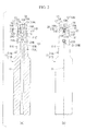
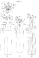
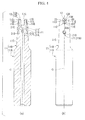
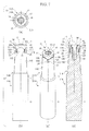
- Fig. 1 through Fig. 6 show the first embodiment of the rotary cutting tool of the present invention.
- the tool body 11 is made of steel, etc., the rear end thereof is provided as a shank portion 11A which is formed approximately in a cylindrical shape at the center of the axis line O, and the leading end is made smaller in diameter than the shank portion 11A and provided as a neck portion 11B formed in a tapered long circular truncated cone shape or cylindrical shape which gradually decreases in the outer diameter slightly toward the leading end side.
- a cutting insert 13 formed in a circular plate shape at the center of the central axis C is mounted on a recessed insert attachment seat 12 formed on the tip surface (leading end surface) of the neck portion 11B so as to be arranged coaxially.
- the neck portion 11B may be formed approximately in a circular truncated cone shape or a cylindrical shape and may be, for example, in a conical shape or a columnar shape having a polygonal cross-section such as a regular dodecagon.
- the insert attachment seat 12 may be formed on the leading end surface thereof.
- the cutting insert 13 is made of a hard material such as cemented carbide and, as shown in Fig. 1 and Fig. 2 , a first circular side surface is provided as a rake face 14 and a second circular side surface is provided as a seating surface 15. Still further, a peripheral surface thereof is provided as a flank 16, and the flank 16 is used as a positive insert having a circular surface formed in a convex conical surface shape so as to gradually decrease in the outer diameter toward the seating surface 15 side.
- a cutting edge 17 which is centered on the central axis C of the cutting insert 13 to assume a circular shape is formed at a ridge line portion where the flank 16 intersects the rake face 14.
- the rake face 14 and the seating surface 15 are formed as flat surfaces perpendicular to the central axis C.
- a mounting hole 19 into which a clamping screw 18 is inserted along the central axis C is formed from the rake face 14 to the seating surface 15.
- the clamping screw 18 is that in which the head portion 18A thereof is formed in a flat countersunk screw head shape as described in the clamping screw 8 of the rotary cutting tool shown in Fig. 17 and Fig. 18 . Therefore, a recessed conical surface portion 19C which is centered on the central axis C with which the back surface of the head portion 18A is in contact is formed also at the mounting hole 19 on the side of the rake face 14.
- a plurality of notched surfaces 16A extending in the tangential direction of a circle which is centered on the central axis C which is coincident with the axis line O of the shank portion 11A are formed in the circumferential direction on the seating surface 15 side of the flank 16 formed in a circular surface shape. That is, in the present embodiment, as described above, the cutting insert 13 is inclined to the seating surface 15 side approximately from the center in the direction of the central axis C of the convex conical surface-like flank 16 which gradually decreases in the outer diameter toward the seating surface 15 from the rake face 14 at an inclination angle larger than an inclination angle with respect to the central axis C of the convex conical surface.
- these eight flat surface-like notched surfaces 16A extending in the tangential direction of the circle which is centered on the central axis C are formed at equal intervals in the circumferential direction so as to provide a rotational symmetry every 45° around the central axis C and also in such a manner that ridge lines where the seating surface 15 intersects notched surfaces adjacent in the circumferential direction intersect each other. Therefore, ridge lines where the seating surface 15 intersects the flank 16 including the notched surfaces 16A assume a regular octagon which is centered on the central axis C.
- the insert attachment seat 12 on which the above-described cutting insert 13 is mounted is also provided with a bottom surface 12A perpendicular to the axis line O which is further recessed from the tip surface to the rear end side in the direction of the axis line O, facing toward the leading end side of the tool body 11, thus opposing to the seating surface 15 of the cutting insert 13, and wall surfaces 12B which extend to the leading end side with respect to the bottom surface 12A and also gradually increase in distance from the axis line O toward the leading end side.
- a threaded hole 12C into which the clamping screw 18 is screwed is formed along the axis line O at the center of the bottom surface 12A.
- the wall surfaces 12B are formed so as to be in contact with four notched surfaces 16A placed alternately in the circumferential direction, among the eight notched surfaces 16A on the flank 16 of the cutting insert 13. That is, to the leading end side in the direction of the axis line O, the wall surfaces 12B are formed so that the wall surfaces 12B is inclined to the axis line O, thereby moving to the outer peripheral side at an inclination angle smaller by 0.1 to 5° and desirably by about 2° than an inclination angle formed by the notched surface 16A with respect to the central axis C.
- the wall surfaces 12B are formed so as to assume an inclined flat surface shape extending in the tangential direction of a circle which is centered on the axis line O.
- the above-described four wall surfaces 12B are arranged so as to provide a rotational symmetry every 90° around the axis line O, corresponding to the four notched surfaces 16A. That is, they are arranged so that a cross-section orthogonal to the axis line O assumes a square.
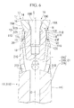
- a plurality of recessed grooves 20 are formed on the bottom surface 12A in such a manner as to extend individually in the circumferential direction of the neck portion 11B, while being recessed from the bottom surface 12A, and also in such a manner as to travel around the insert attachment seat 12 around the axis line O as a whole. Further, each of the recessed grooves 20 is formed in such a manner that the both ends in the circumferential direction are opened from the wall surface 12B of the insert attachment seat 12 to the outer peripheral surface 11C of the neck portion 11B.
- each of the recessed grooves 20 is formed in such a manner so as to extend radially to the outer peripheral side with respect to the axis line O from a circle E which is centered on the axis line O in contact with the recessed groove 20 at the center between the both ends (a circle internally in contact with a square formed by four straight lines passing through the center of the groove width of each recessed groove 20 at a position of the bottom surface 12A in the direction of the axis line O) toward the both ends of the recessed groove 20 which are opened on the outer peripheral surface 11C.
- each of these recessed grooves 20 is in a slit shape which is formed so as to move to the inner peripheral side with respect to the axis line O in the direction of the axis line O toward the groove bottom side (at the rear end side of the tool body 11) from ridge line portions where the four wall surfaces 12B individually intersect the bottom surface 12A of the insert attachment seat 12 and also so as to extend along the intersecting ridge line portions in the circumferential direction. That is, as shown in Fig.
- each of the recessed grooves 20 is formed in a straight line over the entire length so as to extend in the circumferential direction of the neck portion 11B along the tangential direction of the circle E which is centered on the axis line O, when viewed from a direction opposite to the bottom surface 12A.
- the recessed groove 20 extends in an inclined manner so as to move to the inner peripheral side at a constant inclination angle with respect to the axis line O toward the rear end side in the direction of the axis line O.
- this inclination angle is made slightly smaller than an inclination angle formed by the wall surface 12B of the insert attachment seat 12 with respect to the axis line O.
- four recessed grooves 20 are arranged so as to provide a rotational symmetry every 90° around the axis line O, as a whole, assuming approximately a square shape which is externally in contact with the circle E.
- the bottom surface 12A of the insert attachment seat 12 extends so as to run off to the outer peripheral side of the circle E.
- the square made by ridge lines where these recessed grooves 20 intersect the wall surfaces 12B of the insert attachment seat 12 is slightly smaller than a square made by extension lines of the ridge lines where the seating surface 15 intersects these four notched surfaces 16A in a state where the cutting insert 13 is not mounted on the insert attachment seat 12.
- a square made by extension lines of the ridge lines where the seating surface 15 intersects these four notched surfaces 16A in a state where the cutting insert 13 is not mounted on the insert attachment seat 12.
- four peripheral wall portions 11D formed by dividing a space between the recessed grooves 20 and the outer peripheral surface 11C of the neck portion 11B at equal intervals in the circumferential direction are, as will be described later, elastically deformed to the outer peripheral side.
- the wall surfaces 12B are in contact with the notched surfaces 16A.
- the ridge lines where these recessed grooves 20 intersect the wall surface 12B of the insert attachment seat 12 are made coincident with the ridge lines where the seating surface 15 of the cutting insert 13 intersects the above-described four
- the peripheral wall portion 11D formed between the recessed groove 20 and the outer peripheral surface 11C of the neck portion 11B is formed so as to increase in circumferential width toward the groove bottom side of the recessed groove 20 from the bottom surface 12A.
- a circumferential end edge 11E of the peripheral wall portion 11D is formed so as to increase in circumferential width at least on the groove bottom side of the recessed groove 20 as the circumferential end edge 11E moves to the groove bottom side while being recessed and curved.
- the peripheral wall portion 11 D is formed so as to increase in circumferential width at least on the groove bottom side of the recessed groove 20 also as the peripheral wall portion 11D moves radially to the inner peripheral side with respect to the axis line O.
- the circumferential end edge 11E of the peripheral wall portion 11 D is formed so as to increase in circumferential width at least on the groove bottom side of the recessed groove 20 as the circumferential end edge 11E moves radially to the inner peripheral side with respect to the axis line O while being recessed and curved.
- the end edge 11E of the peripheral wall portion 11D is formed so as to provide a recessed curved surface shape by being cut by a ball end mill, etc.
- the recessed curved surface formed by the end edge 11E is formed so as to extend approximately at a constant inclination with respect to the axis line O up to the middle of a recessed groove 20 passing from the wall surface 12B of the insert attachment seat 12 through the bottom surface 12A in the direction of the axis line O, with the peripheral wall portion 11D being increased in circumferential width at a constant ratio and thereafter so as to extend while being recessed and curved to be cut up in the circumferential direction on the groove bottom side of the recessed groove 20, thereby increasing the circumferential width of the peripheral wall portion 11D at a gradually increasing ratio.
- the recessed curved surface formed by the end edge 11E is formed in such a manner that the circumferential width of the peripheral wall portion 11D extends approximately constant radially with respect to the axis line O at a part of the wall surface 12B.
- the recessed curved surface is formed so as to be recessed and curved also at a cross-section perpendicular to the axis line O, with the peripheral wall portion 11D being gradually increased in circumferential width to the inner peripheral side in the radial direction with respect to the axis line O, from the bottom surface 12A of the insert attachment seat 12 to the groove bottom side of the recessed groove 20. Therefore, a ratio at which the peripheral wall portion 11D increases in circumferential width to the inner peripheral side in the radial direction is gradually increased toward the groove bottom side.
- the end edge 11E of the peripheral wall portion 11D is formed in such a manner that the circumferential width of the peripheral wall portion 11D increases to the groove bottom side of the recessed groove 20 and also to the inner peripheral side in the radial direction.
- a clearance is formed which decreases in circumferential width to the groove bottom side of the recessed groove 20 and also decreases in circumferential width at a part of recessed groove 20 to the inner peripheral side in the radial direction as well.
- a wall surface part extending so as to intersect the bottom surface 12A of the insert attachment seat 12 between recessed grooves 20 adjacent in the circumferential direction in the tool body 11 is exposed at this clearance to so as to face the outer peripheral side in the radial direction.
- the groove bottom side of the recessed groove 20 at the wall surface part is formed as a recessed wall portion 11F in which a cross-section orthogonal to the axis line O is formed in a recessed curved surface shape so as to be recessed to the inner peripheral side in the radial direction with respect to the axis line O in synchronization with the end edge 11E of the peripheral wall portion 11D formed in a recessed curved surface shape as described above.
- the recessed wall portion 11F is inclined at a constant inclination angle also in the direction of the axis line O with respect to the axis line O so as to be recessed to the inner peripheral side in the radial direction toward the rear end side from the leading end side of the tool body 11.
- the inclination angle is made approximately equal to a relief angle of the flank 16 of the cutting insert 13 mounted on the insert attachment seat 12.
- the flank 16 and the cutting edge 17 are positioned on an extension of the recessed wall portion 11F to the leading end side.
- a rear end side part of the recessed wall portion 11F in the direction of the axis line O extends beyond the groove bottom of the recessed groove 20 and a rear end edge of the end edge 11E of the peripheral wall portion 11D, thereby positioning slightly further to the rear end side from the end edge 11E.
- the rear end part intersects a bottom surface portion 11 G which is formed approximately in a U letter shape so as to be perpendicular to the recessed wall portion 11F at the rear end part.
- a leading end side part in the direction of the axis line O which intersects the bottom surface 12A of the insert attachment seat 12 is in the present embodiment provided as a chamfered wall portion 11H by being chamfered by a recessed curved surface which is recessed to the inner peripheral side in the radial direction at a curvature radius larger than that of the recessed wall portion 11F on a cross-section orthogonal to the axis line O or by a flat surface.
- the chamfered wall portion 11H intersects the leading end of the recessed wall portion 11F and inclines to the inner peripheral side in the radial direction at a constant inclination angle with respect to the axis line O toward the leading end side thereof.
- the chamfered wall portion 11H extends so as to move to the inner peripheral side in the radial direction with respect to the axis line O as the recessed grooves 20 move to the rear end side in the direction of the axis line O as described above, the chamfered wall portion 11H is formed so as to gradually increase in circumferential width along the leading end side and intersects the bottom surface 12A.
- the bottom surface 12A assumes approximately a lopsided octagonal shape where corners of the square formed with the recessed grooves 20 are chamfered so as to be a recessed curved line larger in curvature radius or a straight line by the chamfered wall portions 11H.
- the length of one side of the lopsided octagon formed with ridge lines where the chamfer wall portions 11H intersect the bottom surface 12A is made shorter than the length of one side of the lopsided octagon formed with ridge lines where the recessed grooves 20 intersect the bottom surface 12A.
- the ridge line where the chamfered wall portion 11H intersects the bottom surface 12A is positioned at the outer peripheral side of the circle E which is centered on the axis line O in contact with a recessed groove 20 at the center of the recessed groove 20 or runs off radially to the outer peripheral side of the circle E so as to be externally in contact with the circle E or intersect therewith.
- the bottom surface 12A of the insert attachment seat 12 which has run off from the circle E to the outer peripheral side extends to the outer peripheral side of the circle E in the radial direction along ridge lines intersecting the chamfered wall portion 11H.
- ridge lines are positioned where the seating surface 15 intersects the remaining four notched surfaces 16A between four notched surfaces 16A in contact with the wall surfaces 12B, among the notched surfaces 16A of the cutting insert 13.
- the corners of the square are chamfered by the chamfered wall portions 11H and allowed to move internally.
- the seating surface 15 of the cutting insert 13 overhangs so as to run off from the bottom surface 12A. Thereby, the tool body 11 is protected at the part concerned.
- each of the recessed grooves 20 is formed so as to extend at a constant width from the side of the bottom surface 12A to the groove bottom side. Then, the recess groove 20 is made slightly larger on the groove bottom than a groove width which is set to be constant and opened to the side of the bottom surface 12A, thereby formed on a circular cross-section larger in diameter than the width of the thus opened groove. Further, the recessed groove 20 is shallower in depth than the threaded hole 12C but made sufficiently larger than, for example, a height of the wall surface 12B from a ridge line where the recessed groove 20 intersects the wall surface 12B to the most tip end of the neck portion 11B.
- a supply hole 21 for coolant is drilled on the tool body 11.
- the supply hole 21 is opened on the groove bottom side of the recessed groove 20 at the neck portion 11B between mutually opposing ends of the recessed grooves 20 adjacent in the circumferential direction.
- a large diameter hole 21A extends to the leading end side along the axis line O from the rear end surface of the shank portion 11A, that is, the rear end surface of the tool body 11.
- the large diameter hole 21 A is thereafter diverged into four branching holes 21 B slightly moving to the leading end side in the direction of the axis line O to the outer peripheral side in the radial direction before reaching the threaded hole 12C of the neck portion 11B.
- an ejection hole 21C smaller in diameter than the branching hole 21B extends from the leading end of each of the branching holes 2 1 B in an inclined manner to the outer peripheral side in the radial direction with respect to the axis line O toward the leading end side, that is, toward the tip side of the neck portion 11 B at an inclination angle smaller than an inclination angle of the branching hole 21B with respect to the axis line O.
- the ejection hole 21C is opened at the bottom surface portion 11G perpendicularly intersecting the recessed wall portion 11F between the recessed grooves 20.
- an inclination angle formed by the ejection hole 21B with respect to the axis line O is approximately equal to an inclination angle formed by the recessed wall portion 11F with respect to the axis line O, that is, approximately equal to a relief angle of the flank 16 of the cutting insert 13.
- the flank 16 and the cutting edge 17 are to be positioned on an extension of the ejection hole 21B to the leading end side, and coolant ejected from an opening of the ejection hole 21B is supplied to the flank 16 of the cutting insert 13 and the cutting edge 17.
- the branching hole 21B is drilled so as to move slightly to the leading end side in the direction of the axis line O to the inner peripheral side in the radial direction with respect to the axis line O from the outer peripheral surface 11C of the neck portion 11B.
- the branching hole 21B is allowed to extend further, thereby extending so as to move slightly to the leading end side in the direction of the axis line O toward the outer peripheral side in the radial direction as described above and stopped before reaching the opposite side of the outer peripheral surface 11C, thereby communicatively connecting to the ejection hole 21C.
- an opening on the outer peripheral surface 11C of the branching hole 21B is sealed with a sealing member 21D such as a plug or a filling screw.
- the cutting insert 13 is seated on the insert attachment seat 12 formed at the tip of the thus constituted tool body 11, with the seating surface 15 facing toward the bottom surface 12A and also the four notched surfaces 16A arranged alternately in the circumferential direction facing toward the wall surface 12B, so as to make each of them seated opposing each other.
- the clamping screw 18 which has been inserted into the mounting hole 19 is screwed into the threaded hole 12C, thereby the head portion 18A of the clamping screw 18 presses the recessed conical surface 19C of the mounting hole 19, by which the cutting insert 13 is mounted on the neck portion 11B of the tool body 11.
- the shank portion 11A of the tool body 11 is retained at a tool retaining portion of a composite processing machine and driven rotationally around the axis line O of the shank portion 11A. And, a work piece is turned by the cutting edge 17 of the cutting insert 13.
- an inclination angle formed by the wall surface 12B of the insert attachment seat 12 with respect to the axis line O is slightly made smaller than an inclination angle formed by the notched surface 16A with respect to the central axis C of the cutting insert 13.
- a square formed by ridge lines where the wall surfaces 12B intersect the recessed grooves 20 is made slightly smaller than a square formed by ridge lines where the notched surfaces 16A intersect the seating surface 15.
- the clamping screw 18 is further screwed into to press the cutting insert 13.
- the seating surface 15 is in contact with the bottom surface 12A of the insert attachment seat 12 and the wall surface 12B is also firmly attached to the notched surface 16A and in contact therewith, the cutting insert 13 is fixed. Therefore, in a state where the cutting insert 13 is mounted on the insert attachment seat 12, as described above, the peripheral wall portion 11D is elastically deformed, by which the wall surface 12B of the insert attachment seat 12 is firmly attached to the notched surface 16A on the peripheral surface (flank 16) of the cutting insert 13 and in contact therewith.
- the center of the peripheral surface that is, the central axis C of the cutting insert 13 coincide with the axis line O of the shank portion 11A. Therefore, even if the cutting insert 13 is a peripheral surface non-polished product lower in cost as described previously, the circular cutting edge 17 continuing to the peripheral surface can be precisely arranged at the center of the axis line O of the shank portion 11A which serves as the rotating center of the tool body 11.
- the seating surface 15 of the cutting insert 13 which is mounted thereon is seated in contact with the bottom surface 12A of the insert attachment seat 12 in which outer peripheral edges on the sides of ridge lines which intersect the remaining four notched surfaces 16A between the four notched surfaces 16A in contact with the wall surface 12B extend so as to run off to the outer peripheral side from the circle E between the mutually opposing ends of adjacent recessed grooves 20. Therefore, even if recessed grooves 20 are formed on the bottom surface 12A so as to travel around the insert attachment seat 12, cutting resistance acting on the cutting edge 17 can be received directly by the thus extended bottom surface 12A to secure rigidity on mounting the cutting insert 13 at a part where the ends of the recessed grooves 20 are provided at intervals.
- the cutting resistance acting on the cutting edge 17 which is positioned directly above the recessed groove 20 can be dispersed and received by a pair of bottom surfaces 12A extending between the both ends of the recessed groove 20 and the respective ends of the recessed grooves 20 adjacent in the circumferential direction. Therefore, according to the above-constituted rotary cutting tool, it is possible to secure high rigidity against the cutting resistance on mounting the insert extending over the entire length of the circular cutting edge 17 and stably perform turning with a high degree of precision. Thus, the cutting insert 13 is mounted stably, making it possible to prevent damaging a tool such as chipping a cutting edge 17.
- the outer peripheral edges on the sides of ridge lines which intersect the remaining four notched surfaces 16A on the seating surface 15 of the cutting insert 13 overhang so as to run off from the bottom surface 12A of the insert attachment seat 12 extending between the mutually opposing ends of recessed grooves 20, as described above. Therefore, the flank 16 (notched surface 16A) of the cutting insert 13 which is made of hard cemented carbide, etc., can be used to protect a ridge line portion where the bottom surface 12A of the tool body 11 made of steel, etc., softer than the cemented carbide intersects a chamfered wall portion 11H.
- the chamfered wall portion 11H, etc. which are exposed between the mutually opposing ends of the recessed grooves 20 spaced in the circumferential direction from a clearance between the mutually opposing end edges 11E of the peripheral wall portion 11D can be prevented from being damaged or deformed by chips made when cutting. And, the cutting insert 13 can be seated and mounted more stably.
- an excessively large overhung amount H from the overhung bottom surface 12A of the seating surface 15 will, as described above, loosen the support of the cutting insert 13 by the bottom surface 12A of the insert attachment seat 12 extending between the mutually opposing ends of the recessed grooves 20, which may affect stable seating of the cutting insert. Therefore, where the cutting insert 13 is overhung and mounted, it is desirable that the seating surface 15 overhang so as to run off from the bottom surface 12A of the insert attachment seat 12 in an overhung amount H in a range of 1.0 mm or less and preferably 0.5 mm or less, as described in the present embodiment.
- each of the recessed grooves 20 is formed in an inclined manner so as to extend to the inner peripheral side in the radial direction with respect to the axis line O of the tool body 11 toward the groove bottom side of the recessed groove 20 from the bottom surface 12A of the insert attachment seat 12.
- the peripheral wall portion 11D is made relatively small in thickness in the radial direction at the tip side of the peripheral wall portion 11D where the wall surfaces 12B of the insert attachment seat 12 in contact with the notched surfaces 16A of the cutting insert 13 are formed, thereby making it possible to cause elastic deformation easily.
- the peripheral wall portion 11D is increased in radial thickness to secure strength and rigidity sufficiently at the peripheral wall portion 11D.
- an inclination angle formed by the inclined recessed groove 20 with respect to the axis line O is made smaller than an inclination angle formed by the wall surface 12B of the insert attachment seat 12. Therefore, elastic deformation is not prevented more than necessary on the groove bottom side of the peripheral wall portion 11D which is increased in radial thickness.
- the recessed groove 30 is inclined at a constant inclination angle with respect to the axis line O to the inner peripheral side in the radial direction toward the groove bottom side.
- the inclination angle is gradually decreased along the groove bottom side and a cross-section of the recessed groove 30 along the axis line O may be formed so as to provide a convex curve line which is raised to the inner peripheral side in the radial direction with respect to the axis line O.
- the inclination angle is gradually increased to the groove bottom side, and a cross-section of the recessed groove 30 along the axis line O may be formed so as to provide a convex curve line which is raised to the outer peripheral side in the radial direction with respect to the axis line O.
- the wall surface 12B of the insert attachment seat 12 be formed in an inclined flat surface shape, the inclination angle of which is kept constant as described above.
- the peripheral wall portion 11D formed between each of the recessed grooves 20 and the outer peripheral surface 11C of the neck portion 11B is formed so as to increase in circumferential width toward the groove bottom side of the recessed groove 20 from the bottom surface 12A of the insert attachment seat 12.
- the peripheral wall portion 11D is formed in such a manner that the end edge 11E thereof is recessed and curved on the groove bottom side of the recessed groove 20 and cut out in the circumferential direction to increase in width.
- the peripheral wall portion 11D is formed so as to be approximately constant in circumferential width to the axis line O in the radial direction, on the wall surface 12 part of the insert attachment seat 12, while formed on the groove bottom side of the recessed groove 20 so as to increase in circumferential width along the inner peripheral side in the radial direction.
- the end edge 11E is formed so as to be recessed and curved at a cross-section orthogonal to the axis line O, by which a ratio at which the circumferential width is increased to the inner peripheral side in the radial direction can be made larger on the groove bottom side.
- the recessed groove 20 is inclined and the circumferential width of the peripheral wall portion 11D is increased to the groove bottom side, it is possible to secure strength and rigidity of the peripheral wall portion 11D more reliably and mount the cutting insert 13 precisely by keeping the displacement amount of elastic deformation on the insert attachment seat 12 side.
- the groove bottom of the recessed groove 20 is formed in a circular shape, the cross-section of which has a larger diameter than a groove width opened on the bottom surface 12A of the recessed groove 20. Therefore, it is possible to prevent the concentration of stress on deformation at a groove bottom part thereof which serves as a supporting point on elastic deformation of the peripheral wall portion 11D. And, it is also possible to prevent the peripheral wall portion 11D from being broken due to the concentration of stress.
- the groove bottom is formed in a circular shape, the cross-section of which is larger in diameter. Thereby, the groove bottom and the outer peripheral surface 11C of the neck portion 11B can be decreased in thickness. It is thus possible to secure a larger amount of elastic deformation of the peripheral wall portion 11D and cope with a greater dimensional change in the cutting insert 13.
- the recessed grooves 20 having the above-described shape of the groove bottom in a single cutting process for one recessed groove 20, for example, by using a ball end mill-like tool in which a spherical cutting edge portion equal in diameter to a circle formed by the cross-section of the groove bottom part is formed at the leading end of an axial cutting edge portion having a diameter equal to the groove width opened on the bottom surface 12A of the recessed groove 20 and delivering the tool from the outer peripheral surface 11C of the neck portion 11B along a tangent of the circle E, with the tool kept parallel with the axis line O.
- the supply hole 21 for coolant is drilled on the tool body 11 to supply the coolant via the supply hole 21 from the tool body 11.
- the coolant can be supplied reliably to the cutting edge 17 and a cut site of a work piece without being prevented by chips, etc.
- the ejection hole 21C is opened between the mutually opposing ends of recessed grooves 20 adjacent in the circumferential direction to eject the coolant on the groove bottom side of the recessed groove 20 at the neck portion 11B of the tool body 11. Therefore, it is possible to supply the coolant more reliably through the clearance between the end edges 11E of adjacent peripheral wall portions 11D between the mutually opposing ends of the recessed grooves 20.
- the supply hole 21 is that in which the large diameter hole 21A is drilled along the axis line O. Therefore, the shank portion 11A can be kept constant in radial thickness to prevent the strength and rigidity thereof from being partially different.
- a grip portion which holds the shank portion 11A may be provided with a coolant supplying hole communicatively connecting to the supply hole 21A on the axis line O which serves as the rotating center of a rotary cutting tool.
- the supply hole 21 for coolant is drilled at the neck portion 11 B of the tool body 11 so as to incline to the outer peripheral side in the radial direction with respect to the axis line O as the ejection hole 21C moves to the tip side of the neck portion 11B, that is, to the leading end side of the tool body 11 on which the cutting insert 13 is mounted.
- the cutting insert 13 is a positive insert.
- the ejection hole 21C and the recessed wall portion 11F extending from the opening thereof to the leading end side are inclined at an inclination angle approximately equal to a relief angle of the flank 16 of the cutting insert 13, thereby the flank 16 and the cutting edge 17 are positioned on the extension thereof.
- each of the above-described plurality of recessed grooves 20 is formed in a straight line so as to extend in the tangential direction of the circle E at the center of the axis line O of the shank portion 11A. Therefore, the process by the above-described ball end mill-like tool in the tangential direction is able to form each of the recessed grooves 20 relatively easily and with a high degree of precision. Thus, as described above, it is possible to arrange the cutting edge 17 at the center of the axis line O at a higher degree of precision and perform turning at a higher degree of precision.
- a plurality of inclined flat surface-like notched surfaces 16A which extend in the tangential direction of the circle at the center of the central axis C are formed in the circumferential direction on the seating surface 15 side of a peripheral surface which serves as the flank 16.
- the wall surface 12B of the insert attachment seat 12 is also formed in an inclined flat surface shape extending in the tangential direction of the circle at the center of the axis line O.
- the plurality of recessed grooves 20 are arranged at a position of rotational symmetry at a constant angle of every 90° at the center of the axis line O, thereby assuming a square shape. Therefore, a plurality of peripheral wall portions 11D formed between these recessed grooves 20 and the outer peripheral surface 11C of the neck portion 11B are formed in such a manner that a cross-section orthogonal to the axis line O is equal in dimensions and shape. It is thus possible to elastically deform the plurality of peripheral wall portions 11D formed as described above more evenly to the outer peripheral side in the radial direction and position the cutting insert 13 more reliably at the center of the axis line O.
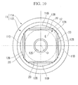
- Fig. 7 to Fig. 10 show the second embodiment of the rotary cutting tool in the present invention.
- Constituents commonly used in the first embodiment will be denoted the same reference numerals to simplify the explanation.
- a head portion 18A thereof is not like a flat countersunk screw head shape as shown in the clamping screw 18 of the first embodiment or in the clamping screw 8 of the rotary cutting tool in Fig. 17 and Fig. 18 but that which has a flat annular back surface. Therefore, an annular flat surface 19A perpendicular to the central axis C with which the back surface is in contact is formed on the side of a rake face 14 also at a mounting hole 19 of a cutting insert 13.
- notched surfaces 16A extending in the tangential direction of a circle which is centered on the central axis C coincident with the axis line O of a shank portion 11A are formed at equal intervals on a seating surface 15 side of a circular surface-like flank 16 in the circumferential direction so as to provide a rotational symmetry every 90° around the central axis C. Therefore, in the present embodiment, ridge lines where the notched surfaces 16A intersect the flank 16 including the seating surface 15 and notched surfaces 16A assume a shape in which four corners of a square notched by the notched surfaces 16A are chamfered by circular arcs which are centered on the central axis C.
- recessed grooves 20 formed on the insert attachment seat 12 are formed so as to be recessed to the rear end side of a tool body 11 parallel with the axis line O from the respective ridge line portions where the bottom surfaces 12A of the insert attachment seat 12 intersect the four wall surfaces 12B.
- end edge 11E which is recessed and curved as described in the first embodiment at a peripheral wall portion 11D formed between each of the recessed grooves 20 and a neck portion 11B is not formed.
- the peripheral wall portion 11D of the second embodiment is approximately constant in width in the direction of the axis line O except a part at which the wall surface 12B of the insert attachment seat 12 is formed.
- the supply hole 21 of coolant on the tool body 11 is not formed.
- the mutually opposing ends of the recessed grooves 20 adjacent in the circumferential direction are formed so as to be spaced slightly also at an outer peripheral surface 11C of a neck portion 11B. Therefore, the outer peripheral surface 11C of the neck portion 11B approximately in a cylindrical shape or a conical surface shape remains between these ends.
- the bottom surface 12A of the insert attachment seat 12 between the mutually opposing ends of the recessed grooves 20 also extends to the outer peripheral surface 11C remaining between the mutually opposing ends of the recessed grooves 20 so as to intersect.
- the bottom surface 12A is formed in such a manner that corners of a square formed by ridge lines intersecting the recessed grooves 20 are formed in an s shape so as to be chamfered in a circular arc shape at the center of the axis line O along the outer peripheral surface 11C of the neck portion 11B.
- a radius of a circular-arc part of the bottom surface 12A extending to the outer peripheral side in the radial direction from the axis line O is made equal to or slightly larger than a radius of the circular arc formed by a ridge line intersecting the flank 16 between the seating surface 15 of the cutting insert 13 and the notched surface 16A from the central axis C.
- the circular arc-like part is chamfered and moved inside, thereby the seating surface 15 of the cutting insert 13 overhangs so as to run off from the bottom surface 12A, for example, in a range of 1.0 mm or less, preferably in a range of about 0.5 mm or less to an extent that will not affect rigidity on mounting the insert, by which the tool body 11 may be protected at the part concerned.
- the back surface of the head portion 18A of the clamping screw 18 and the flat surface 19A of the mounting hole 19 of the cutting insert 13 are perpendicular to the axis line O. Therefore, the cutting insert 13 can be adjusted finely for a radial position with respect to the axis line O.
- the cutting insert 13 seated on the insert attachment seat 12 is pressed to the bottom surface 12A by screwing the clamping screw 18, the cutting insert 13 is finely adjusted for the position in such a manner that counter force of the elastically deformed peripheral wall portion 11D is balanced in the radial direction behind the axis line O.
- the peripheral wall portion 11D is kept equal in the amount of elastic deformation and the four wall surfaces 12B are firmly attached to the four notched surfaces 16A evenly and in contact therewith.
- the centers of the squares formed at cross-sections where the wall surface 12B and the notched surface 12A are orthogonal respectively to the axis line O and the central axis C, that is, the axis line O and the central axis C, are positioned so as to be coaxial.
- the flank peripheral surface
- the notched surface 16A of the cutting insert 13 made of cemented carbide, etc. is a peripheral surface non-polished product which is sintered as it is and, for example, the center of the mounting hole 19 is not strictly coincident with the central axis C of the cutting insert 13 which is the center of the circular cutting edge 17, it is possible to precisely dispose the cutting edge 17 at the center of the axis line O of the shank portion 11A of the tool body 11.
- a ridge line where the seating surface 15 intersects a notched surface 16A of the cutting insert 13 is made coincident with a ridge line where a wall surface 12B of the insert attachment seat 12 intersects a recessed groove 20.
- the recessed groove 20 extends so as to move to the outer peripheral side in the radial direction at the both ends with respect to the circle E in contact with the center thereof, for example, as shown in the first modified example of the second embodiment in Fig.
- a ridge line where the notched surface 16A of the cutting insert 13 intersects the seating surface 15 may be coincident with a ridge line where the bottom surface 12A of the insert attachment seat 12 intersects the recessed groove 20. That is, a whole part of the seating surface 15 may be firmly attached on the bottom surface 12A and in contact therewith.
- each of the recessed grooves 20 may be formed so as to be recessed from the bottom surface 12A more internally than a ridge line where the bottom surface 12A of the insert attachment seat 12 intersects the wall surface 12B.
- the bottom surface 12A remains also on the peripheral wall portion 11D between the recessed groove 20 and the outer peripheral surface 11C of the neck portion 11B. Therefore, the seating surface 15 directly below the cutting edge 17 of the cutting insert 13 is allowed to be in contact with the bottom surface 12A at the peripheral wall portion 11D, thus making it possible to receive cutting resistance acting on the cutting edge 17.
- a ridge line where the notched surface 16A of the cutting insert 13 intersects the seating surface 15 may be positioned between parts opened on the bottom surface 12A of the recessed groove 20.
- openings between the mutually opposing ends of adjacent recessed grooves 20 on the outer peripheral surface 11C of the neck portion 11B are provided at intervals in the circumferential direction and the outer peripheral surface 11C remains therebetween.
- the openings between the mutually opposing ends of these adjacent recessed grooves 20 may be provided so as to be superimposed on each other.
- these mutually opposing ends may intersect with each other to provide openings on alternately different sides in the circumferential direction.
- notched surfaces 16A formed on the cutting insert 13 may be at least equal in number to the wall surfaces 12B.
- the cutting insert 13 in which eight notched surfaces 16A are formed at equal intervals in the circumferential direction to assume a regular octagon on a cross-section orthogonal to the central axis C may be used so that four notched surfaces 16A arranged alternately are in contact with the wall surfaces 12B.
- a plurality of notched surfaces 16A are formed on the seating surface 15 side of a peripheral surface which serves as the flank 16 of the cutting insert 13 as described above.
- a cutting insert 13 that is free of these notched surfaces 16A in which the peripheral surface serving as the flank 16 is formed in a circular surface shape extending over the circumference is mounted detachably on the insert attachment seat 12 to provide a rotary cutting tool.
- This rotary cutting tool may be applied to the present invention.
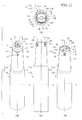
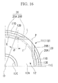
- Fig. 12 to Fig. 16 show the third and the fourth embodiments of the rotary cutting tool of the present invention on which the above-described cutting insert 13 is mounted. Constituents commonly used in the first and the second embodiments will be denoted the same reference numerals to simplify the explanation.
- the cutting insert 13 mounted on the rotary cutting tool described in the third and the fourth embodiments is a positive insert in which, as with the first and the second embodiments, a peripheral surface which serves as the flank 16 is formed in a convex conical surface shape so as to gradually decrease in the outer diameter toward the seating surface 15 side from the rake face 14.
- no notched surface 16A is formed on the seating surface 15 side thereof, and a cross-section orthogonal to the central axis C of the peripheral surface is formed so as to provide a circular shape extending over the entire length in the direction of the central axis C.
- a pair of recessed portions 19B extending in an oval shape in the diametrical direction with respect to the central axis C are formed at an opening on the seating surface 15 side of the mounting hole 19 so as to be opened on the seating surface 15, while communicatively connecting to the mounting hole 19.
- the flank 16 (peripheral surface) of the cutting insert 13 is formed in a convex conical surface shape as a whole.
- the wall surface 12B of the insert attachment seat 12 is formed in a recessed conical surface shape at the center of the axis line O in which the flank 16 is made smaller in inclination angle with respect to the axis line O in a range of 0.1° ° to 5° and preferably at about 2° than an inclination angle with respect to the central axis C, that is, a relief angle formed by the cutting edge 17, and gradually decreased in the inner diameter toward the bottom surface 12A side.
- a cross-section orthogonal to the axis line O is formed so as to be arranged on a circumference at the center of the axis line O extending in the direction of the axis line O.
- a pair of key-type protruding portions 12D accommodated respectively at the recessed portions 19B of the cutting insert 13 are formed around an opening of the threaded hole 12C of the bottom surface 12A.
- a plurality (4) of recessed grooves 20 which are in a slit shape and recessed to the rear end side in the direction of the axis line O from the bottom surface 12A are formed also on the bottom surface 12A of the insert attachment seat 12 so as to extend in the circumferential direction of the neck portion 11B along the tangential direction of a circle E which is centered on the axis line O over the respective entire lengths as shown in Fig. 12 when viewed from the leading end side in the direction of the axis line O and opened on the outer peripheral surface 11C. And, as a whole, these recessed grooves 20 are formed so as to assume a square shape externally in contact with the circle E and travel around the insert attachment seat 12.
- these recessed grooves 20 also extend to the outer peripheral side in the radial direction with respect to the circle E toward the both end sides thereof from the center in contact with the circle E.
- the bottom surface 12A of the insert attachment seat 12 which is also formed so as to assume a square shape extends at the corners of the square extending to the outer peripheral side.
- the wall surface 12B is divided in the circumferential direction by the recessed grooves 20 and can be slightly increased or decreased in the inner diameter in association with elastic deformation of the peripheral wall portion 11D formed between the recessed groove 20 and the outer peripheral surface 11C of the neck portion 11B.
- a circular ridge line where the wall surface 12B of the insert attachment seat 12 formed in a recessed conical surface shape which is centered on the axis line O intersects the bottom surface 12A perpendicular to the axis line O is made larger in diameter than the circle E with which each of the recessed grooves 20 is in contact. Therefore, also in the present embodiment, as described in the second modified example of the second embodiment shown in Fig. 11 (b) , an outer peripheral part of the bottom surface 12A remains so as to continue to the wall surface 12B between a recessed groove 20 and the wall surface 12B at each peripheral wall portion 11D divided circumferentially by this recessed groove 20.
- the cutting insert 13 is accommodated and seated on the thus constituted insert attachment seat 12 in such a manner that the seating surface 15 is opposed to the bottom surface 12A and the protruding portion 12D is loosely fitted into the recess 19B. Further, the clamping screw 18 which has been inserted into the mounting hole 19 is screwed into the threaded hole 12C. Thereby, as with the first and the second embodiments, the seating surface 15 is firmly attached to the bottom surface 12A and in contact therewith, and the flank 16 is in contact with the wall surface 12B. Then, the peripheral wall portion 11D is elastically deformed so as to press and expand the wall surface 12B, by which the cutting insert 13 is mounted on the insert attachment seat 12.
- the cutting insert 13 is a peripheral surface non-polished product lower in cost, the peripheral surface (flank 15) of which is sintered as it is, it is possible to precisely dispose the cutting edge 17 which is positioned on a circular surface formed by the flank 16 at the center of the axis line O of the shank portion 11 A of the tool body 11 and also to perform turning with a high degree of precision.
- the seating surface 15 of the cutting insert 13 is in contact with the bottom surface 12A of the insert attachment seat 12 extending between the ends of the recessed grooves 20. Therefore, cutting resistance acting on the cutting edge 17 can be directly received or dispersed by the thus extended bottom surface 12A to secure rigidity on mounting the insert.
- an outer peripheral part of the bottom surface 12A is formed also at each of the peripheral wall portions 11D divided by a recessed groove 20 in the circumferential direction so as to remain between the recessed groove 20 and the wall surface 12B. Therefore, if the seating surface 15 of the cutting insert 13 is allowed to be in contact with an outer peripheral part of the bottom surface 12A between the recessed groove 20 and the wall surface 12B in a state where the cutting insert 13 is mounted on the insert attachment seat 12, it is possible to support the seating surface 15 directly below the cutting edge 17 by the bottom surface 12A extending over a wider range. As a result, it is possible to further improve rigidity on mounting the insert and perform turning more stably.
- the peripheral surface (flank 16) of the cutting insert 13 is formed so as to be circular at the center of central axis C extending over the circumference and each of the wall surfaces 12B of the insert attachment seat 12 is also formed in a circular-arc surface (recessed circular conical surface) shape in such a manner that a cross-section orthogonal to the axis line O assumes a circular arc positioning on the circumference at the center of the axis line O.
- large loads act on the circular plate-like cutting insert 13 in the circumferential direction when cutting.
- the clamping screw 18 may be loosened or in contrast, the clamping screw 18 may be excessively screwed into the threaded hole 12C, thus resulting in difficulty in detaching the cutting insert 13.
- a protruding portion 12D is formed on the bottom surface 12A of the insert attachment seat 12 and accommodated so as to be loosely fitted into a recess 19B formed on the seating surface 15 of the cutting insert 13, by which the cutting insert 13 is seated on the insert attachment seat 12. For this reason, if the cutting insert 13 is attempted to be rotated in the circumferential direction, the recess 19B is caught at the protruding portion 12D to restrain the rotation of the cutting insert 13. Therefore, it is possible to prevent the clamping screw 18 from being loosened or screwed into excessively.
- each of the recessed grooves 20 does not extend in a straight line over the entire length in the tangential direction of the circle E, as with the first to the third embodiments.
- the recessed groove 20 is formed in such a manner that a center 20A thereof assumes a circular arc shape along the circle E which is centered on the axis line O, when viewed from the leading end side in the direction of the axis line O.
- both ends 20B of the recessed groove 20 extend to the outer peripheral side in the radial direction with respect to the axis line O from the circle E so as to extend along a tangent L of a circle smaller in radius than the circle E toward the both end sides of the recessed groove 20 from the center of the circular arc shape.
- a bottom surface 12A extends between mutually opposing ends 20B adjacent to the recessed grooves 20 which move to the outer peripheral side.
- a part between the circular arc-like center 20A along the circle E of a recessed groove 20 and the ends 20B along the tangent L is formed in a circular arc shape curved in a direction opposite to the center 20A, smoothly continuing to the center 20A and the ends 20B.
- a central angle ⁇ of the circular arc at this part is to be 15° or more.
- the tangent L along which the end 20B extends may be formed in a straight line so as to be common at both ends 20B of one recessed groove 20 or may be formed to be different at the both ends 20B so that extension lines to the center 20A side intersect each other.
- a circular ridge line where the flank 16 of the cutting insert 13 intersects the seating surface 15 is coincident with a circular arc-like ridge line where the wall surface 12B of the insert attachment seat 12 intersects the center 20A of the recessed groove 20.
- an intersection point P of extension lines to the outer peripheral side in the radial direction on the respective ridge lines where the mutually opposing ends 20B of adjacent recessed grooves 20 intersect the bottom surfaces 12A of the insert attachment seat 12 extending between these ends 20B is positioned on a circle F formed by connecting the circular-arc ridge line where the center 20A of each recessed groove 20 intersects the wall surface 12B or positioned outside the circle.
- the wall surface 12B formed at the peripheral wall portion 11D which undergoes elastic deformation is in contact with the flank 16, by which the cutting insert 13 is precisely positioned so that the cutting edge 17 is arranged at the center of the axis line O.
- the intersection point P is positioned outside the circle F, the outer peripheral edge on the seating surface 15 of the cutting insert 13 which is coincident with the circle F is reliably allowed to be in contact with the bottom surface 12A extending between the mutually opposing ends 20B of the adjacent recessed grooves 20. It is, thereby, possible to receive cutting loads sufficiently, acting on the cutting edge 17 and improve rigidity on mounting the insert.
- the center 20A of a recessed groove 20 is formed in a circular arc shape along the circle E at the center of the axis line O. Therefore, the peripheral wall portion 11D formed between the recessed groove 20 and the outer peripheral surface 11C of the neck portion 11B can be decreased in radial thickness at the center 20A. Thus, it is possible to elastically deform the peripheral wall portion 11D at a lower amount and cope with a greater dimensional change in the cutting insert 13.
- the cutting insert 13 described in the first to the fourth embodiments is formed in such a manner that, except the notched surfaces 16A of the cutting insert 13 in the first and the second embodiments, a peripheral surface which serves as the flank 16 is in a convex conical surface shape and extends at a constant inclination angle (relief angle) from the rake face 14 to the seating surface 15.
- a multiple-stage flank may be provided in which the inclination angle is changed in progress to the seating surface 15.
- an inclination angle of the wall surface 12B in the second and the third embodiments may be only made slightly smaller than an inclination angle of the flank 16 on the seating surface 15 side.
- the cutting insert 13 is a positive insert in which the flank 16 is inclined, and the wall surface 12B is firmly attached to the seating surface 15 side of the flank 16 and in contact therewith.
- the present invention is applicable to a negative insert in which the peripheral surface which serves as the flank is provided as a circular peripheral surface (cylindrical surface) parallel with the central axis of the cutting insert.
- the wall surface 12B of the insert attachment seat 12 may be tapered reversely, unlike the above-described embodiments, and formed in a recessed conical surface shape which is centered on the axis line O so as to gradually decrease in the inner diameter away from the bottom surface 12A side.
- the present invention relates to a rotary cutting tool which is provided with a tool body having a shank portion and a neck portion protruding from the shank portion and formed externally in a circular truncated cone shape or a cylindrical shape, a recessed insert attachment seat formed at the tip of the neck portion of the tool body, and a circular plate-like cutting insert which is detachably mounted on the insert attachment seat so as to be coaxial with the axis line of the shank portion, and the rotary cutting tool in which the insert attachment seat is provided with a bottom surface on which a side surface serving as a seating surface of the cutting insert is seated and a wall surface in contact with a peripheral surface of the cutting insert, a plurality of recessed grooves which are recessed from the bottom surface to extend in the circumferential direction of the neck portion, with the both ends being opened to the outer peripheral surface of the neck portion from the wall surface, are formed on the bottom surface so as to travel around the insert attachment seat around the axis line, each of these recessed grooves
- a peripheral surface continuing to the cutting edge is allowed to be in contact with the wall surface of the insert attachment seat, by which the center of the circular cutting edge can be made coincident with the axis line of the shank portion of the tool body.
- the bottom surface of the insert attachment seat is allowed to extend between the mutually opposing ends of the adjacent recessed grooves and an outer peripheral edge of the seating surface directly below the cutting edge is allowed to be in contact with the bottom surface.
Landscapes
- Engineering & Computer Science (AREA)
- Mechanical Engineering (AREA)
- Milling Processes (AREA)
- Cutting Tools, Boring Holders, And Turrets (AREA)
Applications Claiming Priority (2)
| Application Number | Priority Date | Filing Date | Title |
|---|---|---|---|
| JP2008246257 | 2008-09-25 | ||
| PCT/JP2009/004864 WO2010035475A1 (ja) | 2008-09-25 | 2009-09-25 | ロータリバイト |
Publications (2)
| Publication Number | Publication Date |
|---|---|
| EP2340906A1 true EP2340906A1 (de) | 2011-07-06 |
| EP2340906A4 EP2340906A4 (de) | 2013-05-22 |
Family
ID=42059488
Family Applications (1)
| Application Number | Title | Priority Date | Filing Date |
|---|---|---|---|
| EP09815897.5A Withdrawn EP2340906A4 (de) | 2008-09-25 | 2009-09-25 | Rotierendes schneidwerkzeug |
Country Status (4)
| Country | Link |
|---|---|
| US (1) | US8734069B2 (de) |
| EP (1) | EP2340906A4 (de) |
| JP (1) | JP5062329B2 (de) |
| WO (1) | WO2010035475A1 (de) |
Families Citing this family (13)
| Publication number | Priority date | Publication date | Assignee | Title |
|---|---|---|---|---|
| US8459904B2 (en) * | 2010-06-23 | 2013-06-11 | Kennametal Inc. | Cutting insert and holder for rotating applications |
| DE102011110044B4 (de) * | 2011-08-11 | 2013-11-28 | Ferroll Gmbh | Verfahren zum Herstellen einer Zylindereinheit, Schälwerkzeug und Drehmaschine |
| CN103826783B (zh) * | 2011-10-17 | 2016-03-30 | 三菱综合材料株式会社 | 头部交换式切削工具用刀座及头部交换式切削工具 |
| US9776251B2 (en) | 2012-08-10 | 2017-10-03 | Sumitomo Electric Hardmetal Corp. | Lathe turning tool |
| JP6006588B2 (ja) * | 2012-09-04 | 2016-10-12 | 日本特殊陶業株式会社 | 切削工具用ホルダ及び切削工具 |
| EP2818268B1 (de) * | 2013-06-26 | 2017-05-10 | VARGUS Ltd. | Schneideinsatz und Werkzeughalter mit Sitz für Schneideinsatz |
| US9895755B2 (en) * | 2014-12-09 | 2018-02-20 | Kennametal Inc. | Cutting insert with internal coolant passages and method of making same |
| DE102017122054A1 (de) * | 2017-09-22 | 2019-03-28 | Kennametal Inc. | Schneidwerkzeug sowie Verfahren zur Herstellung eines Schneidwerkzeugs |
| JP6432704B1 (ja) * | 2018-04-03 | 2018-12-05 | 株式会社タンガロイ | 切削インサート及び回転切削工具 |
| EP3722710B1 (de) * | 2019-04-12 | 2024-10-02 | Carrier Corporation | Kühleinheit mit atmosphärensteuersystem |
| DE102019127027A1 (de) | 2019-10-08 | 2021-04-08 | Kennametal Inc. | Schneidwerkzeug |
| US20240066604A1 (en) * | 2021-01-07 | 2024-02-29 | Mitsubishi Materials Corporation | Clamping work tool, blade-tip-replaceable cutting tool with clamping work tool, and cutting insert |
| JP7556293B2 (ja) * | 2021-01-07 | 2024-09-26 | 三菱マテリアル株式会社 | 切削インサート、ホルダおよび刃先交換式切削工具 |
Family Cites Families (11)
| Publication number | Priority date | Publication date | Assignee | Title |
|---|---|---|---|---|
| US2153236A (en) * | 1937-04-19 | 1939-04-04 | Packard Motor Car Co | Tool |
| DE3823907A1 (de) * | 1988-07-14 | 1990-01-18 | Feldmuehle Ag | Klemmhalter fuer rundschneidplatten |
| DE10009721A1 (de) * | 2000-03-01 | 2001-09-06 | Komet Stahlhalter Werkzeuge | Maschinenreibahle und Reibkopf für eine Maschinenreibahle |
| JP2002144112A (ja) | 2000-11-01 | 2002-05-21 | Mitsubishi Materials Corp | 円板状のスローアウェイチップのクランプ機構 |
| SE524557C2 (sv) * | 2002-03-21 | 2004-08-24 | Sandvik Ab | Roterande verktyg samt skärdel med flexibla organ fasthållningsorgan samt medbringare |
| US7156006B2 (en) * | 2003-09-02 | 2007-01-02 | Kennametal Inc. | Method and assembly for rotating a cutting insert during a turning operation and inserts used therein |
| US8573901B2 (en) * | 2003-09-02 | 2013-11-05 | Kennametal Inc. | Assembly for rotating a cutting insert during a turning operation and inserts used therein |
| SE0400556D0 (sv) | 2004-03-05 | 2004-03-05 | Pricer Ab | Electronic shelf labelling system, electronic label, handheld device and method in an electronic labelling system |
| SE526990C2 (sv) | 2004-04-20 | 2005-11-29 | Sandvik Intellectual Property | Roterbart skärverktyg för spånavskiljande bearbetning med självcentrerande funktion |
| DE102004023710B4 (de) * | 2004-05-11 | 2014-07-10 | Komet Group Gmbh | Maschinenwerkzeug mit Wechselschneidplatte sowie Wechselschneidplatte für ein Maschinenwerkzeug |
| US7325471B2 (en) * | 2004-09-07 | 2008-02-05 | Kennametal Inc. | Toolholder and cutting insert for a toolholder assembly |
-
2009
- 2009-09-25 WO PCT/JP2009/004864 patent/WO2010035475A1/ja not_active Ceased
- 2009-09-25 US US12/998,171 patent/US8734069B2/en active Active
- 2009-09-25 EP EP09815897.5A patent/EP2340906A4/de not_active Withdrawn
- 2009-09-25 JP JP2010530732A patent/JP5062329B2/ja not_active Expired - Fee Related
Also Published As
| Publication number | Publication date |
|---|---|
| EP2340906A4 (de) | 2013-05-22 |
| US8734069B2 (en) | 2014-05-27 |
| US20110214552A1 (en) | 2011-09-08 |
| JPWO2010035475A1 (ja) | 2012-02-16 |
| WO2010035475A1 (ja) | 2010-04-01 |
| JP5062329B2 (ja) | 2012-10-31 |
Similar Documents
| Publication | Publication Date | Title |
|---|---|---|
| US8734069B2 (en) | Rotary cutting tool | |
| US5951213A (en) | Milling cutter, particularly for copying, and cutting insert therefor | |
| US6616387B2 (en) | Metal cutting tool with direct cutting plate arrangement | |
| US6102630A (en) | Ball nose end mill insert | |
| EP2347841B1 (de) | Schneidewerkzeug mit montier- und abnehmbarem einsatz | |
| EP2764940A1 (de) | Schneideinsatz und schneidwerkzeug mit austauschbarer klinge | |
| US11135657B2 (en) | Interface between a collet holder and a tool adapter | |
| EP3308889A1 (de) | Konischer schaftfräser und schneidkopf | |
| EP2359965A1 (de) | Dreheinsatz, Werkzeugteil, Verfahren sowie ein Maschinenwerkzeug zur spanabhebenden Metallbearbeitung | |
| CN1739897B (zh) | 可转位的切削刀片 | |
| US11801562B2 (en) | Tool for machining a workpiece | |
| JP5310191B2 (ja) | インサート着脱式切削工具 | |
| US8388272B2 (en) | High speed milling cutter with tapered pin | |
| US20100008735A1 (en) | Milling cutter with cam pin and cutting insert therefor | |
| US10286459B2 (en) | Machining tool | |
| JP2014083667A (ja) | 切削インサートおよび刃先交換式切削工具 | |
| WO2012131896A1 (ja) | 刃先交換式切削工具 | |
| US20180178300A1 (en) | Tool for fine machining of bores | |
| JP2006150535A (ja) | 切削工具 | |
| US8702351B2 (en) | Cutter body and locking screw therefor | |
| JP4285527B2 (ja) | 切削ヘッド交換式工具およびそのアーバと切削ヘッドとの締結方法 | |
| JP4640275B2 (ja) | 穴加工工具 | |
| JP7311822B2 (ja) | 刃先交換式切削工具ホルダおよび刃先交換式切削工具 | |
| JP4775065B2 (ja) | 穴加工工具 | |
| EP3199274B1 (de) | Schneidwerkzeug |
Legal Events
| Date | Code | Title | Description |
|---|---|---|---|
| PUAI | Public reference made under article 153(3) epc to a published international application that has entered the european phase |
Free format text: ORIGINAL CODE: 0009012 |
|
| 17P | Request for examination filed |
Effective date: 20110330 |
|
| AK | Designated contracting states |
Kind code of ref document: A1 Designated state(s): AT BE BG CH CY CZ DE DK EE ES FI FR GB GR HR HU IE IS IT LI LT LU LV MC MK MT NL NO PL PT RO SE SI SK SM TR |
|
| AX | Request for extension of the european patent |
Extension state: AL BA RS |
|
| DAX | Request for extension of the european patent (deleted) | ||
| A4 | Supplementary search report drawn up and despatched |
Effective date: 20130423 |
|
| RIC1 | Information provided on ipc code assigned before grant |
Ipc: B23B 27/12 20060101AFI20130417BHEP Ipc: B23B 31/00 20060101ALI20130417BHEP Ipc: B23B 27/16 20060101ALI20130417BHEP |
|
| RIC1 | Information provided on ipc code assigned before grant |
Ipc: B23B 31/00 20060101ALI20160921BHEP Ipc: B23B 27/16 20060101ALI20160921BHEP Ipc: B23B 27/12 20060101AFI20160921BHEP |
|
| GRAP | Despatch of communication of intention to grant a patent |
Free format text: ORIGINAL CODE: EPIDOSNIGR1 |
|
| INTG | Intention to grant announced |
Effective date: 20161028 |
|
| STAA | Information on the status of an ep patent application or granted ep patent |
Free format text: STATUS: THE APPLICATION IS DEEMED TO BE WITHDRAWN |
|
| 18D | Application deemed to be withdrawn |
Effective date: 20170308 |