EP2340902A1 - Guss von internen Funktionen in einem Produkt - Google Patents
Guss von internen Funktionen in einem Produkt Download PDFInfo
- Publication number
- EP2340902A1 EP2340902A1 EP10192345A EP10192345A EP2340902A1 EP 2340902 A1 EP2340902 A1 EP 2340902A1 EP 10192345 A EP10192345 A EP 10192345A EP 10192345 A EP10192345 A EP 10192345A EP 2340902 A1 EP2340902 A1 EP 2340902A1
- Authority
- EP
- European Patent Office
- Prior art keywords
- core
- sections
- insert member
- cast
- product
- Prior art date
- Legal status (The legal status is an assumption and is not a legal conclusion. Google has not performed a legal analysis and makes no representation as to the accuracy of the status listed.)
- Granted
Links
Images


Classifications
-
- B—PERFORMING OPERATIONS; TRANSPORTING
- B22—CASTING; POWDER METALLURGY
- B22C—FOUNDRY MOULDING
- B22C9/00—Moulds or cores; Moulding processes
- B22C9/10—Cores; Manufacture or installation of cores
- B22C9/103—Multipart cores
-
- Y—GENERAL TAGGING OF NEW TECHNOLOGICAL DEVELOPMENTS; GENERAL TAGGING OF CROSS-SECTIONAL TECHNOLOGIES SPANNING OVER SEVERAL SECTIONS OF THE IPC; TECHNICAL SUBJECTS COVERED BY FORMER USPC CROSS-REFERENCE ART COLLECTIONS [XRACs] AND DIGESTS
- Y10—TECHNICAL SUBJECTS COVERED BY FORMER USPC
- Y10T—TECHNICAL SUBJECTS COVERED BY FORMER US CLASSIFICATION
- Y10T428/00—Stock material or miscellaneous articles
- Y10T428/24—Structurally defined web or sheet [e.g., overall dimension, etc.]
- Y10T428/24273—Structurally defined web or sheet [e.g., overall dimension, etc.] including aperture
- Y10T428/24322—Composite web or sheet
- Y10T428/24331—Composite web or sheet including nonapertured component
Definitions
- the present invention relates to cast products having internal features and more particularly, although not exclusively, a casting process for producing products having cooling passages therein.
- cooling passages for components which operate in use within high temperature environments is one example in which such complex internal passages are required. Cooling of components is of particular importance for high temperature gas turbine engines in order to ensure that components within the engine are maintained at a suitable operational temperature without deterioration to performance. It is widely acknowledged that the use of internal cooling channels can allow components to operate effectively in hot environments which exceed the melting temperature of the component material.
- Cooling in this manner typically requires a plurality of successive cooling chambers to be defined by internal wall formations in the component. Flow between those chambers is permitted by the provision of openings in the walls such that flow entering a first chamber passes into a second chamber via said openings and then into a further chamber from the second chamber by virtue of further openings.
- the openings are arranged such that the flow impinges on the surfaces to be cooled in the relevant chambers prior to passing into another chamber.
- cooling passages are preferable from an operational point of view
- the formation of such chambers and openings by way of casting or moulding is a complex process.
- a core is required which defines the shape of the interior of the component. The core is removed to leave the negative internal space within the component once formed.
- exit apertures must be provided in the component in order to allow removal of the core.
- the spine is a manufacturing feature and, once removed, leaves unwanted apertures in the final component.
- Exit apertures due to removal of a spine and/or the core itself are undesirable in the final component and can cause short circuits or otherwise prevent correct operation of the internal cooling network. Accordingly these passages need to be closed in the final component.
- Conventional methods of closing the exit apertures involve brazing or welding of closures, which methods are time consuming and can cause detrimental thermal stresses in the final component. Repeated thermal loading of the component can lead to problems on account of thermal stresses, such as cracking or component failure.
- a method of forming a cast product comprising: providing a core having a plurality of sections and one or more gaps there-between, wherein the core comprises an insert member spanning the gap between adjacent sections of the core; locating the core within a mould; introducing a liquid phase material into the gap between the core bodies in the mould; allowing the liquid phase material to solidify in the gap so as to form a feature of a resulting solid product; and removing the core sections from the solid product such that the insert member remains securely held within the feature.
- the feature comprises an internal feature in the resulting product.
- the cast features are internal walls within the resulting product.
- the feature may comprise a wall, which may be provided between internal cavities or chambers of the product.
- the insert member may comprise a material which is different to the material of the remainder of the core.
- the insert member may be formed of a first material and the core sections are formed of a second material, wherein the first and second materials are different.
- the insert member may comprise or consist of a metal or ceramic material.
- the core sections may be formed of a ceramic material.
- the core sections define internal cavities within the resulting product.
- the plurality of sections may comprise a plurality of first sections and the core may comprises a plurality of further sections.
- the further sections may depend from the first sections and may be connected thereto by one or more pedestals.
- the first sections, the further sections and the pedestals may be formed of the same material.
- the further sections may be of smaller volume than the first sections.
- the core may define a network of internal cooling cavities in the resulting product.
- the insert member may comprise opposing retaining features, shaped to retain the insert member in the feature of the solid product once cast.
- the insert member may comprise a neck region and opposing retaining formations depending therefrom.
- the insert member may comprise a tapered portion and may comprise a pair of opposingly tapered portions.
- the core comprises one or more retaining formations for positioning the core within the mould.
- the retaining formations may comprise arm members depending outwardly there-from and the arm members may be received within corresponding locating formations in the mould.
- the retaining members may be arranged so as to suspend the core within the mould.
- the resulting product is a gas turbine engine component.
- a mould core for use in an investment casting process, the core comprising: a plurality of sections spaced by a gap there-between and an insert member having a first portion located in a first section and an opposing portion located in a second core section so as to span the gap there-between; wherein the insert member is formed of a material which is different to the material of the core sections.
- a cast product comprising a plurality of internal cavities and one or more internal walls there-between, said cavities in combination defining an internal cooling passage within the product, the one or more internal walls comprising an aperture having an insert member therein, said insert member comprising a neck portion seated within the aperture and opposing retaining portions depending outwardly from said neck portion so as to retain the insert member within the wall.
- the insert member may be formed of a single solid body.
- a gas turbine engine comprising a product according to the third aspect.
- an insert member for use in the creation of cast product according to the first aspect.
- a ducted fan gas turbine engine generally indicated at 10 has a principal and rotational axis 11.
- the engine 10 comprises, in axial flow series, an air intake 12, a propulsive fan 13, an intermediate pressure compressor 14, a high-pressure compressor 15, combustion equipment 16, a high-pressure turbine 17, and intermediate pressure turbine 18, a low-pressure turbine 19 and a core engine exhaust nozzle 20.
- a nacelle 21 generally surrounds the engine 10 and defines the intake 12, a bypass duct 22 and a bypass exhaust nozzle 23.
- the gas turbine engine 10 works in a conventional manner so that air entering the intake 12 is accelerated by the fan 13 to produce two air flows: a first air flow into the intermediate pressure compressor 14 and a second air flow which passes through a bypass duct 22 to provide propulsive thrust.
- the intermediate pressure compressor 14 compresses the air flow directed into it before delivering that air to the high pressure compressor 15 where further compression takes place.
- the compressed air exhausted from the high-pressure compressor 15 is directed into the combustion equipment 16 where it is mixed with fuel and the mixture combusted.
- the resultant hot combustion products then expand through, and thereby drive the high, intermediate and low-pressure turbines 17, 18, 19 before being exhausted through the nozzle 20 to provide additional propulsive thrust.
- the high, intermediate and low-pressure turbines 17, 18, 19 respectively drive the high and intermediate pressure compressors 15, 14 and the fan 13 by suitable interconnecting shafts.
- Alternative gas turbine engine arrangements may comprise a two, as opposed to three, shaft arrangement and/or may provide for different bypass ratios.
- Other configurations known to the skilled person include open rotor designs, such as turboprop engines, or else turbojets, in which the bypass duct is removed such that all air flow passes through the core engine.
- the various available gas turbine engine configurations are typically adapted to suit an intended operation which may include aerospace, marine, power generation amongst other propulsion or industrial pumping applications.
- the present invention is particularly suited to components which may be manufactured using investment casting techniques, which may be otherwise referred to a 'lost wax' castings.
- Such components may be mounted in the vicinity of the turbines 17 to 19 - particularly the high pressure turbine 17 - and may comprise seal segments which form a closely-fitting rim or ring about the turbine or else vanes, such as nozzle guide vanes immediately downstream of the turbine.
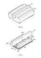
- Figure 2 shows an example of a component which may be formed according to the present invention in the form of a turbine seal segment 30.
- the component 30 has a cast body 32 in which are defined a plurality of internal features or structures in the form of walls 34 and 35.
- a first set of internal walls 34 depend inwardly from outer wall 36 so as to define a series of larger internal cavities or chambers 38.
- a second set of internal walls 35 depend inwardly from external wall 40 so as to define a second series of relatively smaller internal chambers 42.
- the first 38 and second 42 sets of internal chambers are separated by internal wall 44.
- Internal wall 44 extends generally laterally across the component 30 between opposing side walls, whereas the internal walls 34 and 35 are generally perpendicular thereto, so as to define generally right-angled internal chambers 38 and 42. Additional formations in the form of turbulators are cast into the walls of the smaller internal chambers 42 to promote heat transfer between the chamber walls and a coolant flowing there-through.
- a plurality of apertures 46 and 48 are provided in the internal wall 44.
- the apertures 46 provide inlets into the second chambers 42 from the relevant first chamber 38, whereas the apertures 48 provide an outlet from the second chambers 42 to the relevant first chamber 38.
- coolant can thus flow from the left-most chamber 38A via apertures 46A into the chamber 42A there-beneath.
- the coolant exits chamber 42A into the central chamber 38B via apertures 48B.
- Coolant enters chamber 42B from central chamber 38B via apertures 46B and passes there-along prior to exiting into chamber 38C via apertures 48C. From chamber 38C, coolant can enter chamber 42C via apertures 46C.
- cascade cooling Internal cooling of component in this manner by passage of coolant into and from successive chambers may be referred to herein as cascade cooling or cascade impingement cooling.
- coolant undergoes multiple passes to and from a surface to be cooled (in this case external wall 40) prior to exiting the component. This has a beneficial impact on cooling efficiency.
- investment casting is used to form body 30 within a mould (not shown).
- the material 50 from which the body 30 is formed is cast about a core member 52 as shown in figure 3 .
- the core member 52 is substantially formed of a ceramic material although other known core materials may be used.
- the core member 52 is removed from the material 50 once cast using conventional techniques as would be known to the person skilled in the art. The remaining material 50 is then machined and/or otherwise processed and/or treated in order to result in the component 30.
- the core member 52 is shown in isolation in figure 4 .
- the core member 52 comprises a plurality of sections which form the corresponding internal cavities in the final component.
- the sections 54A, 54B and 54C respectively form the chambers 46A, 46B and 46C in the final component.
- the sections 54A, 54B and 54C are spaced by gaps 55 which form walls 34 in the final component.
- the gaps 55 are continuous such that walls 34 have no apertures therein, which would serve to short-circuit the cascade cooling gas path in the final component.
- the series of sections 56A, 56B and 56C respectively form the individual cooling passageways 42A, 42B and 42C as shown in figure 2B .
- the sections 56 are suspended from sections 54 by ties or pedestals 58 formed of the same core material, which, when removed, form the apertures 46 and 48 in the final component.
- the intricate and delicate nature of the core 52 results in a need to support the core sections throughout at least some stages of the component manufacturing process.
- core insert members 60 as shown in figures 5 and 6 , which span the gaps between core sections and serve to hold the core sections in a fixed relative position.
- FIG. 5 An exemplary cross section of a core 62 which comprises two adjacent core sections 64, separated by a gap 66, is shown in figure 5 .
- This embodiment would produce a component having two main internal chambers, rather than the three chambers 38 shown in figure 2 .
- the invention may be applied to a core having two or more core sections and a corresponding component produced thereby to have two or more internal chambers.
- the core 62 is shown held within a mould, which is depicted schematically at 68.
- the core 62 has support features in the form of arms 70 and 72 depending outwardly there-from and which are received in corresponding location formations in the mould 68.
- the core insert members 60 also help to maintain tolerances to the cast surface in conjunction with the arms 70, 72 which project out of the casting.
- the core insert member 60 is formed of a different material to the core 62 and associated arms 70, 72.
- the insert member 60 is formed of a Zirconia or Alumina material although any material which is capable of withstanding the casting process/melt temperatures may be used provided it meets the functional requirements of the component in which it is to be inserted.
- the core insert member 60 is doubly tapered in shape so as to form a neck region 61 at its centre which is smaller in dimension than its opposing sides.
- the insert member is generally circular in plan such that its shape may be likened to a unison of two opposing frusto-conical halves.
- the insert member may otherwise be described as being generally hourglass shaped.
- molten material can be allowed to enter the mould 68 to thereby form the component body about the core 62.
- various optional methods for casting are available which may include casting within a vacuum, single crystal casting or directionally solidified castings, any of which may be use din conjunction with the present invention.
- the component is removed from the mould 68 and the core removed there-from using conventional techniques.
- the core insert member 60 being formed of a different material to that of the core, is maintained within the internal wall of the core body.
- the cast component can be machined and otherwise treated as required for use.
- the insert member 60 remains in the core throughout the casting process and is then ultimately retained by the metal cast around it.
- FIG. 6 An example of such a component is shown in section in figure 6 , in which the core insert members 60 are held fast within the cast internal walls 74.
- the shape of the members 60 ensure that they cannot slide out from the walls in which they are cast.
- the dual taper of the members ensure that the insert members are resilient to operational fluid pressures which may be applied to the component in use.
- the thermal expansion properties of the members 60 are typically closely matched to that of the component material. Any slight discrepancy therein may be accommodated for by the dual taper of the member, such that the member cannot come loose. Whilst it is acknowledged that a portion of the member 60 will protrude form the wall 74 into the internal cavity, such protrusion is not considered to cause undue detriment to the efficiency of the cascade cooling circuit.
- the taper and dimensions of the core insert member may be tailored to suit the operational requirements for the end component. For example the taper may be increased for components which will undergo relatively high coolant pressure loading in use.
- the insert member described above provides a solution to the problems associated with removable/soluble core investment casting, which is effective in terms of cost and function. Further specific advantages of the invention are considered to include:
- the location of the insert member in the wall is not critical since it is a free, cast-in feature.
- the invention may be applied to nozzle guide vanes or other cast components for which internal features require the use of delicate and/or complex cores.
Landscapes
- Engineering & Computer Science (AREA)
- Mechanical Engineering (AREA)
- Molds, Cores, And Manufacturing Methods Thereof (AREA)
- Turbine Rotor Nozzle Sealing (AREA)
Applications Claiming Priority (1)
| Application Number | Priority Date | Filing Date | Title |
|---|---|---|---|
| GBGB0921818.1A GB0921818D0 (en) | 2009-12-15 | 2009-12-15 | Casting of internal features within a product ( |
Publications (2)
| Publication Number | Publication Date |
|---|---|
| EP2340902A1 true EP2340902A1 (de) | 2011-07-06 |
| EP2340902B1 EP2340902B1 (de) | 2014-01-22 |
Family
ID=41667057
Family Applications (1)
| Application Number | Title | Priority Date | Filing Date |
|---|---|---|---|
| EP10192345.6A Active EP2340902B1 (de) | 2009-12-15 | 2010-11-24 | Guss von internen Funktionen in einem Produkt |
Country Status (3)
| Country | Link |
|---|---|
| US (1) | US9038706B2 (de) |
| EP (1) | EP2340902B1 (de) |
| GB (1) | GB0921818D0 (de) |
Cited By (1)
| Publication number | Priority date | Publication date | Assignee | Title |
|---|---|---|---|---|
| JP2014223674A (ja) * | 2013-05-14 | 2014-12-04 | ゼネラル・エレクトリック・カンパニイ | 固定コアタイロッド |
Families Citing this family (14)
| Publication number | Priority date | Publication date | Assignee | Title |
|---|---|---|---|---|
| SG11201600235TA (en) | 2013-07-31 | 2016-02-26 | United Technologies Corp | Castings and manufacture methods |
| GB201411332D0 (en) | 2014-06-26 | 2014-08-13 | Rolls Royce Plc | Core positioning |
| US10099276B2 (en) | 2015-12-17 | 2018-10-16 | General Electric Company | Method and assembly for forming components having an internal passage defined therein |
| US10046389B2 (en) | 2015-12-17 | 2018-08-14 | General Electric Company | Method and assembly for forming components having internal passages using a jacketed core |
| US9968991B2 (en) | 2015-12-17 | 2018-05-15 | General Electric Company | Method and assembly for forming components having internal passages using a lattice structure |
| US9987677B2 (en) | 2015-12-17 | 2018-06-05 | General Electric Company | Method and assembly for forming components having internal passages using a jacketed core |
| US10099283B2 (en) | 2015-12-17 | 2018-10-16 | General Electric Company | Method and assembly for forming components having an internal passage defined therein |
| US9579714B1 (en) | 2015-12-17 | 2017-02-28 | General Electric Company | Method and assembly for forming components having internal passages using a lattice structure |
| US10099284B2 (en) | 2015-12-17 | 2018-10-16 | General Electric Company | Method and assembly for forming components having a catalyzed internal passage defined therein |
| US10137499B2 (en) | 2015-12-17 | 2018-11-27 | General Electric Company | Method and assembly for forming components having an internal passage defined therein |
| US10150158B2 (en) | 2015-12-17 | 2018-12-11 | General Electric Company | Method and assembly for forming components having internal passages using a jacketed core |
| US10118217B2 (en) | 2015-12-17 | 2018-11-06 | General Electric Company | Method and assembly for forming components having internal passages using a jacketed core |
| US10286450B2 (en) | 2016-04-27 | 2019-05-14 | General Electric Company | Method and assembly for forming components using a jacketed core |
| US10335853B2 (en) | 2016-04-27 | 2019-07-02 | General Electric Company | Method and assembly for forming components using a jacketed core |
Citations (8)
| Publication number | Priority date | Publication date | Assignee | Title |
|---|---|---|---|---|
| US1586321A (en) * | 1922-12-28 | 1926-05-25 | Charles F Newport | Sectional core |
| EP0715913A1 (de) * | 1992-02-05 | 1996-06-12 | Howmet Corporation | Mehrteilige Kerne für Feingussverfahren |
| EP0904872A1 (de) * | 1997-09-25 | 1999-03-31 | Hottinger Maschinenbau GmbH | Verbindung von Kernen |
| US6068806A (en) * | 1996-10-28 | 2000-05-30 | United Technologies Corporation | Method of configuring a ceramic core for casting a turbine blade |
| US20020051706A1 (en) * | 2000-10-27 | 2002-05-02 | Hartmut Haehnle | Cooled component, casting core for manufacturing such a component, as well as method for manufacturing such a component |
| EP1543896A2 (de) * | 2003-12-19 | 2005-06-22 | United Technologies Corporation | Giesskernen zum Präzisionsgiessen |
| EP1604753A1 (de) * | 2004-05-06 | 2005-12-14 | United Technologies Corporation | Genauguss |
| EP1923152A1 (de) * | 2006-11-14 | 2008-05-21 | United Technologies Corporation | Verfahren zum Gießen von Tragflächen |
Family Cites Families (16)
| Publication number | Priority date | Publication date | Assignee | Title |
|---|---|---|---|---|
| JPS5257021A (en) | 1975-11-07 | 1977-05-11 | Nippon Musical Instruments Mfg | Method of manufacturing cylinder |
| JPS5568168A (en) | 1978-11-16 | 1980-05-22 | Keiichiro Miyazaki | Insert casting method of pipe body of holed casting |
| US4691754A (en) * | 1985-12-31 | 1987-09-08 | Deere & Company | Method for forming castings having inserts |
| GB8800686D0 (en) | 1988-01-13 | 1988-02-10 | Rolls Royce Plc | Method of supporting core in mould |
| JP2764071B2 (ja) | 1988-10-31 | 1998-06-11 | イズミ工業株式会社 | 内燃機関用ピストンの製造方法 |
| US5810552A (en) | 1992-02-18 | 1998-09-22 | Allison Engine Company, Inc. | Single-cast, high-temperature, thin wall structures having a high thermal conductivity member connecting the walls and methods of making the same |
| JPH0760402A (ja) | 1993-08-30 | 1995-03-07 | Aisin Takaoka Ltd | カムシャフト用中子および中空カムシャフトの鋳造方法 |
| US5853044A (en) * | 1996-04-24 | 1998-12-29 | Pcc Airfoils, Inc. | Method of casting an article |
| JP3417331B2 (ja) | 1998-05-14 | 2003-06-16 | トヨタ自動車株式会社 | シリンダヘッド及びその製造方法 |
| EP1122456B1 (de) | 2000-03-09 | 2001-08-16 | Freni Brembo S.p.A. | Belüftete Scheibe für Scheibenbremse |
| US6637500B2 (en) * | 2001-10-24 | 2003-10-28 | United Technologies Corporation | Cores for use in precision investment casting |
| US6883700B2 (en) | 2002-09-26 | 2005-04-26 | Siemens Westinghouse Power Corporation | Turbine blade closure system |
| JP4222030B2 (ja) | 2003-01-10 | 2009-02-12 | いすゞ自動車株式会社 | 鋳物製作時の中子合わせ部のシール構造および金属製シールマット |
| US20050087319A1 (en) * | 2003-10-16 | 2005-04-28 | Beals James T. | Refractory metal core wall thickness control |
| US7144220B2 (en) * | 2004-07-30 | 2006-12-05 | United Technologies Corporation | Investment casting |
| JP2007061891A (ja) | 2005-09-02 | 2007-03-15 | Yanmar Co Ltd | 鋳鉄の鋳造方法及びその方法を使用した内燃機関用シリンダヘッドの製造方法 |
-
2009
- 2009-12-15 GB GBGB0921818.1A patent/GB0921818D0/en not_active Ceased
-
2010
- 2010-11-24 EP EP10192345.6A patent/EP2340902B1/de active Active
- 2010-11-24 US US12/953,963 patent/US9038706B2/en active Active
Patent Citations (8)
| Publication number | Priority date | Publication date | Assignee | Title |
|---|---|---|---|---|
| US1586321A (en) * | 1922-12-28 | 1926-05-25 | Charles F Newport | Sectional core |
| EP0715913A1 (de) * | 1992-02-05 | 1996-06-12 | Howmet Corporation | Mehrteilige Kerne für Feingussverfahren |
| US6068806A (en) * | 1996-10-28 | 2000-05-30 | United Technologies Corporation | Method of configuring a ceramic core for casting a turbine blade |
| EP0904872A1 (de) * | 1997-09-25 | 1999-03-31 | Hottinger Maschinenbau GmbH | Verbindung von Kernen |
| US20020051706A1 (en) * | 2000-10-27 | 2002-05-02 | Hartmut Haehnle | Cooled component, casting core for manufacturing such a component, as well as method for manufacturing such a component |
| EP1543896A2 (de) * | 2003-12-19 | 2005-06-22 | United Technologies Corporation | Giesskernen zum Präzisionsgiessen |
| EP1604753A1 (de) * | 2004-05-06 | 2005-12-14 | United Technologies Corporation | Genauguss |
| EP1923152A1 (de) * | 2006-11-14 | 2008-05-21 | United Technologies Corporation | Verfahren zum Gießen von Tragflächen |
Cited By (1)
| Publication number | Priority date | Publication date | Assignee | Title |
|---|---|---|---|---|
| JP2014223674A (ja) * | 2013-05-14 | 2014-12-04 | ゼネラル・エレクトリック・カンパニイ | 固定コアタイロッド |
Also Published As
| Publication number | Publication date |
|---|---|
| US20110143090A1 (en) | 2011-06-16 |
| US9038706B2 (en) | 2015-05-26 |
| GB0921818D0 (en) | 2010-01-27 |
| EP2340902B1 (de) | 2014-01-22 |
Similar Documents
| Publication | Publication Date | Title |
|---|---|---|
| EP2340902B1 (de) | Guss von internen Funktionen in einem Produkt | |
| US20150202683A1 (en) | Method of making surface cooling channels on a component using lithographic molding techniques | |
| EP1010859B1 (de) | Kühlsystem für eine Turbinenschaufel mit einem Dreiwegekühlkanal | |
| US10040115B2 (en) | Additively manufactured casting articles for manufacturing gas turbine engine parts | |
| US10415403B2 (en) | Cooled blisk for gas turbine engine | |
| KR20090127913A (ko) | 가스 터빈 엔진의 안내 날개 어셈블리에 대한 안내 날개 덕트 요소 | |
| EP3214274B1 (de) | Eingekapselte kühlung für turbinenummantelungen | |
| EP3273005B1 (de) | Luftgekühlte komponente für einen gasturbinenmotor | |
| US10844732B2 (en) | Aerofoil and method of manufacture | |
| EP3090145A1 (de) | Gasturbinenmotorkomponente kühlkanalturbulator | |
| EP3898026B1 (de) | Verfahren zur herstellung eines kerns zum giessen einer gasturbinenkomponente | |
| US20150322815A1 (en) | Cast steel frame for gas turbine engine | |
| US8277193B1 (en) | Thin walled turbine blade and process for making the blade | |
| US8511977B2 (en) | Heat transfer passage | |
| EP3269929B1 (de) | Gasturbinenmotorkomponente mit kühlkanälen in der wand und verfahren zur herstellung davon | |
| EP1541809B1 (de) | Gasturbinenleitschaufel und entsprechendes Bildungsverfahren | |
| EP3011140B1 (de) | Gasturbinenmotorkomponente mit stützrippen | |
| US7681623B2 (en) | Casting process and cast component | |
| WO2019046036A1 (en) | METHOD FOR REALIZING A TURBINE AERODYNAMIC PROFILE | |
| EP3433036B1 (de) | Verfahren zur herstellung eines hybridisierten kerns mit hervorstehendem guss in kühlelementen für feinguss | |
| EP3533532A1 (de) | Kern für ein feingussverfahren | |
| US20200208530A1 (en) | Method for making a turbine airfoil |
Legal Events
| Date | Code | Title | Description |
|---|---|---|---|
| PUAI | Public reference made under article 153(3) epc to a published international application that has entered the european phase |
Free format text: ORIGINAL CODE: 0009012 |
|
| AK | Designated contracting states |
Kind code of ref document: A1 Designated state(s): AL AT BE BG CH CY CZ DE DK EE ES FI FR GB GR HR HU IE IS IT LI LT LU LV MC MK MT NL NO PL PT RO RS SE SI SK SM TR |
|
| AX | Request for extension of the european patent |
Extension state: BA ME |
|
| 17P | Request for examination filed |
Effective date: 20111208 |
|
| RIC1 | Information provided on ipc code assigned before grant |
Ipc: B22C 9/10 20060101AFI20130808BHEP |
|
| GRAP | Despatch of communication of intention to grant a patent |
Free format text: ORIGINAL CODE: EPIDOSNIGR1 |
|
| INTG | Intention to grant announced |
Effective date: 20131031 |
|
| GRAS | Grant fee paid |
Free format text: ORIGINAL CODE: EPIDOSNIGR3 |
|
| GRAA | (expected) grant |
Free format text: ORIGINAL CODE: 0009210 |
|
| AK | Designated contracting states |
Kind code of ref document: B1 Designated state(s): AL AT BE BG CH CY CZ DE DK EE ES FI FR GB GR HR HU IE IS IT LI LT LU LV MC MK MT NL NO PL PT RO RS SE SI SK SM TR |
|
| REG | Reference to a national code |
Ref country code: GB Ref legal event code: FG4D |
|
| REG | Reference to a national code |
Ref country code: CH Ref legal event code: EP |
|
| REG | Reference to a national code |
Ref country code: AT Ref legal event code: REF Ref document number: 650530 Country of ref document: AT Kind code of ref document: T Effective date: 20140215 |
|
| REG | Reference to a national code |
Ref country code: IE Ref legal event code: FG4D |
|
| REG | Reference to a national code |
Ref country code: DE Ref legal event code: R096 Ref document number: 602010013255 Country of ref document: DE Effective date: 20140306 |
|
| REG | Reference to a national code |
Ref country code: NL Ref legal event code: VDEP Effective date: 20140122 |
|
| REG | Reference to a national code |
Ref country code: AT Ref legal event code: MK05 Ref document number: 650530 Country of ref document: AT Kind code of ref document: T Effective date: 20140122 |
|
| REG | Reference to a national code |
Ref country code: LT Ref legal event code: MG4D |
|
| PG25 | Lapsed in a contracting state [announced via postgrant information from national office to epo] |
Ref country code: NO Free format text: LAPSE BECAUSE OF FAILURE TO SUBMIT A TRANSLATION OF THE DESCRIPTION OR TO PAY THE FEE WITHIN THE PRESCRIBED TIME-LIMIT Effective date: 20140422 Ref country code: LT Free format text: LAPSE BECAUSE OF FAILURE TO SUBMIT A TRANSLATION OF THE DESCRIPTION OR TO PAY THE FEE WITHIN THE PRESCRIBED TIME-LIMIT Effective date: 20140122 Ref country code: IS Free format text: LAPSE BECAUSE OF FAILURE TO SUBMIT A TRANSLATION OF THE DESCRIPTION OR TO PAY THE FEE WITHIN THE PRESCRIBED TIME-LIMIT Effective date: 20140522 |
|
| PG25 | Lapsed in a contracting state [announced via postgrant information from national office to epo] |
Ref country code: CY Free format text: LAPSE BECAUSE OF FAILURE TO SUBMIT A TRANSLATION OF THE DESCRIPTION OR TO PAY THE FEE WITHIN THE PRESCRIBED TIME-LIMIT Effective date: 20140122 Ref country code: AT Free format text: LAPSE BECAUSE OF FAILURE TO SUBMIT A TRANSLATION OF THE DESCRIPTION OR TO PAY THE FEE WITHIN THE PRESCRIBED TIME-LIMIT Effective date: 20140122 Ref country code: ES Free format text: LAPSE BECAUSE OF FAILURE TO SUBMIT A TRANSLATION OF THE DESCRIPTION OR TO PAY THE FEE WITHIN THE PRESCRIBED TIME-LIMIT Effective date: 20140122 Ref country code: FI Free format text: LAPSE BECAUSE OF FAILURE TO SUBMIT A TRANSLATION OF THE DESCRIPTION OR TO PAY THE FEE WITHIN THE PRESCRIBED TIME-LIMIT Effective date: 20140122 Ref country code: PT Free format text: LAPSE BECAUSE OF FAILURE TO SUBMIT A TRANSLATION OF THE DESCRIPTION OR TO PAY THE FEE WITHIN THE PRESCRIBED TIME-LIMIT Effective date: 20140522 Ref country code: SE Free format text: LAPSE BECAUSE OF FAILURE TO SUBMIT A TRANSLATION OF THE DESCRIPTION OR TO PAY THE FEE WITHIN THE PRESCRIBED TIME-LIMIT Effective date: 20140122 Ref country code: NL Free format text: LAPSE BECAUSE OF FAILURE TO SUBMIT A TRANSLATION OF THE DESCRIPTION OR TO PAY THE FEE WITHIN THE PRESCRIBED TIME-LIMIT Effective date: 20140122 |
|
| PG25 | Lapsed in a contracting state [announced via postgrant information from national office to epo] |
Ref country code: HR Free format text: LAPSE BECAUSE OF FAILURE TO SUBMIT A TRANSLATION OF THE DESCRIPTION OR TO PAY THE FEE WITHIN THE PRESCRIBED TIME-LIMIT Effective date: 20140122 Ref country code: RS Free format text: LAPSE BECAUSE OF FAILURE TO SUBMIT A TRANSLATION OF THE DESCRIPTION OR TO PAY THE FEE WITHIN THE PRESCRIBED TIME-LIMIT Effective date: 20140122 Ref country code: LV Free format text: LAPSE BECAUSE OF FAILURE TO SUBMIT A TRANSLATION OF THE DESCRIPTION OR TO PAY THE FEE WITHIN THE PRESCRIBED TIME-LIMIT Effective date: 20140122 Ref country code: BE Free format text: LAPSE BECAUSE OF FAILURE TO SUBMIT A TRANSLATION OF THE DESCRIPTION OR TO PAY THE FEE WITHIN THE PRESCRIBED TIME-LIMIT Effective date: 20140122 |
|
| REG | Reference to a national code |
Ref country code: DE Ref legal event code: R097 Ref document number: 602010013255 Country of ref document: DE |
|
| PG25 | Lapsed in a contracting state [announced via postgrant information from national office to epo] |
Ref country code: RO Free format text: LAPSE BECAUSE OF FAILURE TO SUBMIT A TRANSLATION OF THE DESCRIPTION OR TO PAY THE FEE WITHIN THE PRESCRIBED TIME-LIMIT Effective date: 20140122 Ref country code: CZ Free format text: LAPSE BECAUSE OF FAILURE TO SUBMIT A TRANSLATION OF THE DESCRIPTION OR TO PAY THE FEE WITHIN THE PRESCRIBED TIME-LIMIT Effective date: 20140122 Ref country code: EE Free format text: LAPSE BECAUSE OF FAILURE TO SUBMIT A TRANSLATION OF THE DESCRIPTION OR TO PAY THE FEE WITHIN THE PRESCRIBED TIME-LIMIT Effective date: 20140122 Ref country code: DK Free format text: LAPSE BECAUSE OF FAILURE TO SUBMIT A TRANSLATION OF THE DESCRIPTION OR TO PAY THE FEE WITHIN THE PRESCRIBED TIME-LIMIT Effective date: 20140122 |
|
| PG25 | Lapsed in a contracting state [announced via postgrant information from national office to epo] |
Ref country code: SK Free format text: LAPSE BECAUSE OF FAILURE TO SUBMIT A TRANSLATION OF THE DESCRIPTION OR TO PAY THE FEE WITHIN THE PRESCRIBED TIME-LIMIT Effective date: 20140122 Ref country code: PL Free format text: LAPSE BECAUSE OF FAILURE TO SUBMIT A TRANSLATION OF THE DESCRIPTION OR TO PAY THE FEE WITHIN THE PRESCRIBED TIME-LIMIT Effective date: 20140122 |
|
| PLBE | No opposition filed within time limit |
Free format text: ORIGINAL CODE: 0009261 |
|
| STAA | Information on the status of an ep patent application or granted ep patent |
Free format text: STATUS: NO OPPOSITION FILED WITHIN TIME LIMIT |
|
| 26N | No opposition filed |
Effective date: 20141023 |
|
| REG | Reference to a national code |
Ref country code: DE Ref legal event code: R097 Ref document number: 602010013255 Country of ref document: DE Effective date: 20141023 |
|
| PG25 | Lapsed in a contracting state [announced via postgrant information from national office to epo] |
Ref country code: SI Free format text: LAPSE BECAUSE OF FAILURE TO SUBMIT A TRANSLATION OF THE DESCRIPTION OR TO PAY THE FEE WITHIN THE PRESCRIBED TIME-LIMIT Effective date: 20140122 |
|
| PG25 | Lapsed in a contracting state [announced via postgrant information from national office to epo] |
Ref country code: LU Free format text: LAPSE BECAUSE OF FAILURE TO SUBMIT A TRANSLATION OF THE DESCRIPTION OR TO PAY THE FEE WITHIN THE PRESCRIBED TIME-LIMIT Effective date: 20141124 Ref country code: MC Free format text: LAPSE BECAUSE OF FAILURE TO SUBMIT A TRANSLATION OF THE DESCRIPTION OR TO PAY THE FEE WITHIN THE PRESCRIBED TIME-LIMIT Effective date: 20140122 |
|
| REG | Reference to a national code |
Ref country code: CH Ref legal event code: PL |
|
| PG25 | Lapsed in a contracting state [announced via postgrant information from national office to epo] |
Ref country code: LI Free format text: LAPSE BECAUSE OF NON-PAYMENT OF DUE FEES Effective date: 20141130 Ref country code: CH Free format text: LAPSE BECAUSE OF NON-PAYMENT OF DUE FEES Effective date: 20141130 |
|
| REG | Reference to a national code |
Ref country code: IE Ref legal event code: MM4A |
|
| PG25 | Lapsed in a contracting state [announced via postgrant information from national office to epo] |
Ref country code: IE Free format text: LAPSE BECAUSE OF NON-PAYMENT OF DUE FEES Effective date: 20141124 |
|
| REG | Reference to a national code |
Ref country code: FR Ref legal event code: PLFP Year of fee payment: 6 |
|
| PG25 | Lapsed in a contracting state [announced via postgrant information from national office to epo] |
Ref country code: SM Free format text: LAPSE BECAUSE OF FAILURE TO SUBMIT A TRANSLATION OF THE DESCRIPTION OR TO PAY THE FEE WITHIN THE PRESCRIBED TIME-LIMIT Effective date: 20140122 |
|
| PG25 | Lapsed in a contracting state [announced via postgrant information from national office to epo] |
Ref country code: BG Free format text: LAPSE BECAUSE OF FAILURE TO SUBMIT A TRANSLATION OF THE DESCRIPTION OR TO PAY THE FEE WITHIN THE PRESCRIBED TIME-LIMIT Effective date: 20140122 Ref country code: IT Free format text: LAPSE BECAUSE OF FAILURE TO SUBMIT A TRANSLATION OF THE DESCRIPTION OR TO PAY THE FEE WITHIN THE PRESCRIBED TIME-LIMIT Effective date: 20140122 Ref country code: GR Free format text: LAPSE BECAUSE OF FAILURE TO SUBMIT A TRANSLATION OF THE DESCRIPTION OR TO PAY THE FEE WITHIN THE PRESCRIBED TIME-LIMIT Effective date: 20140423 |
|
| PG25 | Lapsed in a contracting state [announced via postgrant information from national office to epo] |
Ref country code: MT Free format text: LAPSE BECAUSE OF FAILURE TO SUBMIT A TRANSLATION OF THE DESCRIPTION OR TO PAY THE FEE WITHIN THE PRESCRIBED TIME-LIMIT Effective date: 20140122 Ref country code: HU Free format text: LAPSE BECAUSE OF FAILURE TO SUBMIT A TRANSLATION OF THE DESCRIPTION OR TO PAY THE FEE WITHIN THE PRESCRIBED TIME-LIMIT; INVALID AB INITIO Effective date: 20101124 Ref country code: TR Free format text: LAPSE BECAUSE OF FAILURE TO SUBMIT A TRANSLATION OF THE DESCRIPTION OR TO PAY THE FEE WITHIN THE PRESCRIBED TIME-LIMIT Effective date: 20140122 |
|
| REG | Reference to a national code |
Ref country code: FR Ref legal event code: PLFP Year of fee payment: 7 |
|
| REG | Reference to a national code |
Ref country code: FR Ref legal event code: PLFP Year of fee payment: 8 |
|
| PGFP | Annual fee paid to national office [announced via postgrant information from national office to epo] |
Ref country code: DE Payment date: 20171129 Year of fee payment: 8 |
|
| PGFP | Annual fee paid to national office [announced via postgrant information from national office to epo] |
Ref country code: GB Payment date: 20171127 Year of fee payment: 8 |
|
| PG25 | Lapsed in a contracting state [announced via postgrant information from national office to epo] |
Ref country code: MK Free format text: LAPSE BECAUSE OF FAILURE TO SUBMIT A TRANSLATION OF THE DESCRIPTION OR TO PAY THE FEE WITHIN THE PRESCRIBED TIME-LIMIT Effective date: 20140122 |
|
| PG25 | Lapsed in a contracting state [announced via postgrant information from national office to epo] |
Ref country code: AL Free format text: LAPSE BECAUSE OF FAILURE TO SUBMIT A TRANSLATION OF THE DESCRIPTION OR TO PAY THE FEE WITHIN THE PRESCRIBED TIME-LIMIT Effective date: 20140122 |
|
| REG | Reference to a national code |
Ref country code: DE Ref legal event code: R119 Ref document number: 602010013255 Country of ref document: DE |
|
| GBPC | Gb: european patent ceased through non-payment of renewal fee |
Effective date: 20181124 |
|
| PG25 | Lapsed in a contracting state [announced via postgrant information from national office to epo] |
Ref country code: DE Free format text: LAPSE BECAUSE OF NON-PAYMENT OF DUE FEES Effective date: 20190601 |
|
| PG25 | Lapsed in a contracting state [announced via postgrant information from national office to epo] |
Ref country code: GB Free format text: LAPSE BECAUSE OF NON-PAYMENT OF DUE FEES Effective date: 20181124 |
|
| P01 | Opt-out of the competence of the unified patent court (upc) registered |
Effective date: 20230528 |
|
| PGFP | Annual fee paid to national office [announced via postgrant information from national office to epo] |
Ref country code: FR Payment date: 20251124 Year of fee payment: 16 |