EP2340375B1 - Integriertes abgedichtetes und schmierungsfreies schwenksystem - Google Patents
Integriertes abgedichtetes und schmierungsfreies schwenksystem Download PDFInfo
- Publication number
- EP2340375B1 EP2340375B1 EP09767209.1A EP09767209A EP2340375B1 EP 2340375 B1 EP2340375 B1 EP 2340375B1 EP 09767209 A EP09767209 A EP 09767209A EP 2340375 B1 EP2340375 B1 EP 2340375B1
- Authority
- EP
- European Patent Office
- Prior art keywords
- pair
- pivot assembly
- axis
- accordance
- members
- Prior art date
- Legal status (The legal status is an assumption and is not a legal conclusion. Google has not performed a legal analysis and makes no representation as to the accuracy of the status listed.)
- Active
Links
Images
Classifications
-
- F—MECHANICAL ENGINEERING; LIGHTING; HEATING; WEAPONS; BLASTING
- F16—ENGINEERING ELEMENTS AND UNITS; GENERAL MEASURES FOR PRODUCING AND MAINTAINING EFFECTIVE FUNCTIONING OF MACHINES OR INSTALLATIONS; THERMAL INSULATION IN GENERAL
- F16C—SHAFTS; FLEXIBLE SHAFTS; ELEMENTS OR CRANKSHAFT MECHANISMS; ROTARY BODIES OTHER THAN GEARING ELEMENTS; BEARINGS
- F16C11/00—Pivots; Pivotal connections
- F16C11/02—Trunnions; Crank-pins
-
- F—MECHANICAL ENGINEERING; LIGHTING; HEATING; WEAPONS; BLASTING
- F16—ENGINEERING ELEMENTS AND UNITS; GENERAL MEASURES FOR PRODUCING AND MAINTAINING EFFECTIVE FUNCTIONING OF MACHINES OR INSTALLATIONS; THERMAL INSULATION IN GENERAL
- F16C—SHAFTS; FLEXIBLE SHAFTS; ELEMENTS OR CRANKSHAFT MECHANISMS; ROTARY BODIES OTHER THAN GEARING ELEMENTS; BEARINGS
- F16C33/00—Parts of bearings; Special methods for making bearings or parts thereof
- F16C33/02—Parts of sliding-contact bearings
- F16C33/04—Brasses; Bushes; Linings
- F16C33/06—Sliding surface mainly made of metal
- F16C33/10—Construction relative to lubrication
-
- F—MECHANICAL ENGINEERING; LIGHTING; HEATING; WEAPONS; BLASTING
- F16—ENGINEERING ELEMENTS AND UNITS; GENERAL MEASURES FOR PRODUCING AND MAINTAINING EFFECTIVE FUNCTIONING OF MACHINES OR INSTALLATIONS; THERMAL INSULATION IN GENERAL
- F16C—SHAFTS; FLEXIBLE SHAFTS; ELEMENTS OR CRANKSHAFT MECHANISMS; ROTARY BODIES OTHER THAN GEARING ELEMENTS; BEARINGS
- F16C33/00—Parts of bearings; Special methods for making bearings or parts thereof
- F16C33/72—Sealings
- F16C33/74—Sealings of sliding-contact bearings
Definitions
- This invention relates generally to a pivot system that allows two machine element members to pivot around a fixed axis, and more specifically, to an extended life integrated, sealed and lube free machine pivot system which controls, integrates, seals and allows two machine element members to pivot around a fixed axis.
- a hinge journalled in bearings have one or more bearings arranged inside one machine member and a cylindrical pin hinging through the bearing and a pair of mounting lugs without mounting hole locking capabilities, attached by various methods to the outside of one mounting lug, to prevent the pin from falling out when linkage wear appears.
- the surface between the cylindrical part of the pin and the inner diameter of the bearing is greased through a grease channel, either through the pin or through the connecting machine member and the bushing.
- DE10309792 discloses a bearing bolt with tapered end pieces and slotted clamping rings according to the preamble of claim 1 that are cylindrical on the outside and tapered on the inside for detachable mounting of both end pieces in bores of a machine part.
- US2003/0150140 discloses a coupling device which has such a structure that a metal based contact material capable of storing a lubricating oil and/or lubricant is interposed between an implement bushing made from steel and implement pin of an implement for construction equipment.
- US3600015 discloses a pivot pin structure that includes a pivot pin having a central journal portion opposite and integral tapered ends; split sleeves having internal frustoconical shaped surfaces that engage the tapered ends; and a pair of plates threadedly attached to opposite ends of the sleeves for moving the sleeves axially inwardly relative to the tapered ends of the pin.
- the present invention is a pivot system that will allows two machine element members to pivot around a fixed axis.
- the pivot system is an extremely wear resistant integrated, sealed and lube free machine pivot system comprising a range of functionalities.
- the pivot system will allow two machine element members to pivot around a fixed axis with reduced wear thereby reducing the breakdown of the linkage.
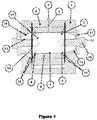
- the pivot system provides an integrated system for a machine pivot where an integrated pivot system axis member 13, mechanically locked into a pair of mounting lug members 1 by means of a pair of expansion sleeve members 15, and one or more lube free, sealed pivoting lubricant chamber members 7 positioned in the housing 2 in the machine member, rotating around the axis member 13 of the extended life, integrated machine pivot system, thereby preventing the disadvantages described above.
- the pivot system has an axis member 13.
- a channel is formed in the axis member 13.
- the channel may run only a portion of the length of the axis member 13 so that an opening/partial channel is formed in each end of the axis member.
- the channel may run an entire length of the axis member 13.
- end sections of the channel are threaded.
- the end sections of the axis member 13 may be provided with external threading.
- a pair of end members 14 is formed on each end of the axis member 13.
- the end members 14 are tapered so that the distal end of the end members 14 is narrower than the proximal end.
- the end members 14 may be cylindrical in shape as well.
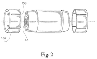
- the pivot system has a pair of expansion sleeve members 15.
- Each expansion sleeve member 15 interacts with one formed end member 14 of the axis member 13 and a corresponding hole formed in one of the mounting lug members 1.
- each expansion sleeve 15 has a housing 15A.
- the housing 15A is cylindrical in shape while the end member 14 of the axis member 13 is conical.
- the housing 15A is conical in shape while the end member 14 is cylindrical.
- Each housing 15A is hollow and has a pair of open ends.
- a plurality of slots 15B is formed in the housing 15A and goes through the housing 15A into the hollow section of the housing 15A.
- the slots 15B generally run along a length of the housing 15A. At least one of the pluralities of slots 15B will run an entire length of the housing 15A.
- the slots 15B act as annular wedges, with the apex pointing towards the central section of the axis member 13.
- the number of slots 15B formed in the housing 15A is based on the diameter of the housing 15A. The larger the diameter of the housing 15A the more slots 15B are generally needed. In general, four to six slots 15B are formed in each housing 15A.
- the slots 15B will run vertically down the side of the housing 15A.
- One slot 15B may run the length of the housing 14.
- the housing 15A is generally made of a sturdy metallic material.
- the expansion sleeve members 15 are used for anchoring the axis member 13 in the holes of the respective mounting lug members 1.
- the expansion sleeve members 15 provide a metallic locking mechanism between itself and the holes formed in the mounting lug member 1.
- the expansion sleeve members 15 eliminates any wear in the holes of the pivot mounting lug members 1 as well as creating a perfect stability of the surface of the axis member 13 for one or more non metallic high wear resistant cylindrical or split pivoting lubricant chamber members 7 to integrate and rotate around the axis member 13. This is accomplished by the expansion sleeve members 15 expanding and pressing against the interior walls of the holes.
- the respective expansion sleeve member 15 expands over the end members 14 of the axis member 13 by means of a locking device.
- the locking device applies pressure on the expansion sleeve members 15.
- the slots 15B in the expansion sleeve members 15 allow the expansion sleeve members 15 to expand and press against the interior walls of the openings in the mounting
- the pivot system uses a pair of locking devices.
- Each locking device is used to secure a respective expansion sleeve members 15 in the proper hole formed in the mounting lug members 1.
- the locking devices are a pair of tension washers 17 and a pair of locking members 18.
- the locking member 18 has a threaded end member 16 and a head member 22. When inserted into the channel, the threaded end member 16 will extend coaxially into the channel of the axis member 13. The thread end member 16 will engage threads formed in the channel. The head member 22 of the locking member 18 engages the expansion sleeve 15 so as to apply pressure to the corresponding expansion sleeve member 15. The pressure causes the expansion sleeve member 15 to expand and press against the interior walls of the hole 1A formed in the mounting lug members 1.
- a tension washer member 17 may also be provided.
- the tension washer member 17 has an opening formed through a central area thereof through which the locking member 18 is inserted.
- the tension washer member 17 is positioned so that a smooth side of the tension washer member 17 faces the expansion sleeve member 15.
- the tension washer member 17 is used to apply pressure to one of the pair of expansion sleeve member 15 in order to cause the expansion sleeve member 15 to expand and press against the interior walls of the hole formed in the mounting lug members 1.
- the tension washer member 17 is designed in a strong metal with properties allowing a static tension to be built up, and kept, between the head member 22 and the threaded end member 16 of the locking member 18.
- the axis member 13 has two or more friction seal grooves 6 formed on the exterior cylindrical surface thereof.
- the friction seal grooves 6 are generally formed at each end of the axis member 13 in front of the end members 14.
- the friction seal grooves 6 are integrate with an equal number of lube free rotating friction seals 5.
- An axis chamber member 3 formed around the central area of the axis member 13. In other words, the axis chamber member 3 is formed and positioned between the two end members 14.
- a gap is formed between the axis chamber member 3 and the axis member 13 to form one or more metallic or non-metallic high wear resistant, cylindrical or split, pivoting lubricant chamber member 7.
- the pivoting lubricant chamber member 7 is used to store lubrication around the axis member 13.
- a friction seal groove 4 is formed in the axis chamber member 3. The friction seal grooves 4 formed in the axis chamber member 3 and the corresponding friction seal groove 6 in the axis member 13 are used to secure the friction seals 5 in place to prevent the shifting of the friction seals 5.
- the friction seals 5 form an annular sealing around the axis member 13 and the axis chamber member 3 thereby preventing the lubricant applied to the axis member 13 and stored in the pivoting lubricant chamber member 7 from leaking out.
- the axis member 13 can integrate one or more metallic or non-metallic high wear resistant, cylindrical or split, pivoting lubricant chamber members 7. If the pivoting lubricant chamber member 7 is split, the surfaces facing each other when integrated have a number of indentations and knobs fitting into each other to ensure the integrity of the pivoting lubricant chamber member 7 when integrated.
- a lubrication channel 8 is in fluid communication with the pivoting lubricant chamber member 7.
- the lubrication channel 8 provides a pathway to inject a lubricant into the pivoting lubricant chamber member 7.
- the lubrication channel 8 runs through a machine member housing 2 and the axis chamber member 3 to the pivoting lubricant chamber member 7.
- a nipple member 9 is attached to an end of the lubrication channel 8.
- the nipple member 9 is generally attached to an end opposite to the pivoting lubricant chamber member 7.
- the nipple member 9 allows the lubricant to be injected into the lubrication channel 8 while prevent the lubricant from exiting out of the nipple member 9.
- a lubrication channel can be added to the axis member 13.
- the extended life, sealed and lube free machine pivot system also includes one or more pairs of sealed friction spacers 10 engineered to integrate within the machine pivot system by being seated between the system pivoting lubricant chamber member 7 and the mounting lug member on the respective side of the pivot system.
- the sealed system friction spacer member 10 has a groove 11 directly opposite the groove in the cylindrical surface on both sides of the cylindrical or split pivoting lubricant chamber member 7, as well as on the opposite side, facing the respective pivot mounting lug members 1.
- a pair of lube free rotating friction seals 12 is integrated, one on each side.
- the friction spacer members 10 ensure against axial movement in pivot system and provide additional sealing of the lube free machine pivots.
Landscapes
- Engineering & Computer Science (AREA)
- General Engineering & Computer Science (AREA)
- Mechanical Engineering (AREA)
- Pivots And Pivotal Connections (AREA)
- Component Parts Of Construction Machinery (AREA)
Claims (11)
- Schwenkanordnung zum Sichern eines Paars von Befestigungslaschen (1) und Stabilisieren eines Maschinenelements mit:einem axialen Element (13), das ein erstes Endelement und ein zweites Endelement (14) hat, wobei eine Öffnung sowohl in dem ersten als auch in dem zweiten Endelement (14) gebildet ist;einem Paar von Dehnhülsen (15), wobei je eine Dehnhülse das Paars von Dehnhülsen (15) über dem ersten Ende und dem zweiten Ende (14) des axialen Elements (13) positioniert ist;einem Paar von Verriegelungseinrichtungen (18), wobei eine Verriegelungseinrichtung (18) in die Öffnung eingefügt ist, die in dem jeweiligen Ende des axialen Elements (13) gebildet ist, wobei die Verriegelungseinrichtungen (18) in das Paar von Dehnhülsen (15) eingreifen, wobei sie verursachen, dass sich die Dehnhülsen ausdehnen, um das axiale Element (13) in den Befestigungslaschen (1) zu sichern;dadurch gekennzeichnet, dass
ein Kammerelement (3) um einen zentralen Bereich des axialen Elements (13) gebildet ist;
mindestens ein Schmiermittelkammerelement (7) zwischen dem zentralen Bereich des axialen Elements (13) und dem Kammerelement (7) gebildet ist; wobei die Schwenkanordnung zudem aufweist:ein Paar von Reibdichtungselementen (5), wobei je ein Reibdichtungselement an dem jeweiligen Ende des axialen Elements (13) und an dem Kammerelement (3) angebracht ist, um eine Ringdichtung um das axiale Element (13) und das Kammerelement (3) zu bilden, um zu verhindern, dass ein Schmiermittel in dem Schmiermittelkammerelement (7) austritt, wobei die Schwenkanordnung ferner ein Paar von Achsdichtungsnuten (6) aufweist, wobei je eine Achsdichtungsnut (6) in dem jeweiligen Ende des axialen Elements (13) gebildet ist; und ein Paar von Dichtungsnuten (4), die um einen Innenumfang des Kammerelements (3) gebildet sind, wobei je eine Dichtungsnut (4) in dem jeweiligen Ende des Kammerelements (3) gebildet ist;wobei jede Achsdichtungsnut des Paars von Achsdichtungsnuten (6) mit einer entsprechenden in dem Kammerelement (3) gebildeten Dichtungsnut (4) ausgerichtet ist und ein entsprechendes Reibdichtungselement (5) hält. - Schwenkanordnung nach Anspruch 1, die zudem aufweist:einen Schmierkanal (8), der sich in Fluidaustausch mit dem mindestens einen Schmiermittelkammerelement (7) befindet; undeinen Schmiernippel (9), der an einem Ende des Schmiermittelkanals (8) angebracht ist.
- Schwenkanordnung nach einem der vorherigen Ansprüche,
die zudem ein Paar von abgedichteten Reibdistanzstücken (10) aufweist, wobei das Paar von Reibdistanzstücken zwischen dem Kammerelement (3) und dem Befestigungslaschenelement (1) positionierbar ist. - Schwenkanordnung nach Anspruch 3, die zudem aufweist:eine Vielzahl von Distanzstückdichtungsnuten (11); undein Paar von Distanzstückdichtungen, die auf jedem Ende von jedem abgedichteten Reibdistanzstück (10) gebildet sind, wobei jede Distanzstückdichtung in eine entsprechende Distanzstückdichtungsnut (11) eingreift.
- Schwenkanordnung nach einem der vorherigen Ansprüche,
wobei das erste Ende und das zweite Ende (14) des axialen Elements (13) konisch sind, so dass ein distales Ende von sowohl dem ersten als auch dem zweiten Endelement schmaler ist als ein proximales Ende des ersten und zweiten Endelements. - Schwenkanordnung nach Anspruch 5,
wobei jede Dehnhülse des Paars von Dehnhülsen (15) eine zylindrische Form aufweist. - Schwenkanordnung nach Anspruch 6,
wobei jede Dehnhülse des Paars von Dehnhülsen (15) aufweist:eine Einhausung (15A), die ein hohles Inneres und ein Paar von offenen Enden hat; undeine Vielzahl von Schlitzen (15B), die entlang einer Länge der Einhausung verlaufen. - Schwenkanordnung nach Anspruch 7,
wobei die Vielzahl von Schlitzen (15B) sich durch die Einhausung (15A) in das hohle Innere erstreckt. - Schwenkanordnung nach Anspruch 8,
wobei mindestens ein Schlitz der Vielzahl von Schlitzen (15B) über eine gesamte Länge der Einhausung (15A) und in das hohle Innere verläuft. - Schwenkanordnung nach einem der vorherigen Ansprüche,
wobei jede Verriegelungseinrichtung (18) aufweist:ein Gewindestiftelement (16); undein Kopfelement (22), das mit einem Ende des Stiftelements gekoppelt ist. - Schwenkanordnung nach Anspruch 10,
die zudem ein Spannscheibenelement (17) aufweist, das eine Öffnung hat, die durch einen zentralen Bereich desselben gebildet ist, durch die das Gewindestiftelement (16) eingefügt ist.
Applications Claiming Priority (2)
| Application Number | Priority Date | Filing Date | Title |
|---|---|---|---|
| US12/141,262 US7784152B2 (en) | 2008-06-18 | 2008-06-18 | Integrated sealed and lube free pivot system |
| PCT/US2009/043466 WO2009154897A1 (en) | 2008-06-18 | 2009-05-11 | Integrated sealed and lube free pivot system |
Publications (3)
| Publication Number | Publication Date |
|---|---|
| EP2340375A1 EP2340375A1 (de) | 2011-07-06 |
| EP2340375A4 EP2340375A4 (de) | 2013-03-20 |
| EP2340375B1 true EP2340375B1 (de) | 2016-08-17 |
Family
ID=41429748
Family Applications (1)
| Application Number | Title | Priority Date | Filing Date |
|---|---|---|---|
| EP09767209.1A Active EP2340375B1 (de) | 2008-06-18 | 2009-05-11 | Integriertes abgedichtetes und schmierungsfreies schwenksystem |
Country Status (3)
| Country | Link |
|---|---|
| US (1) | US7784152B2 (de) |
| EP (1) | EP2340375B1 (de) |
| WO (1) | WO2009154897A1 (de) |
Families Citing this family (5)
| Publication number | Priority date | Publication date | Assignee | Title |
|---|---|---|---|---|
| US8783796B2 (en) * | 2010-06-18 | 2014-07-22 | Caterpillar Inc. | Pin for use in track rollers and bogie assemblies |
| NO344877B1 (no) * | 2017-10-30 | 2020-06-15 | Bondura Tech As | Leddbolt forsynt med utstyr for registrering av belastning |
| GB202003133D0 (en) * | 2020-03-04 | 2020-04-15 | Stanley David William | Improvements in and relating to pin joints |
| CN113775636A (zh) * | 2021-08-27 | 2021-12-10 | 中国煤炭科工集团太原研究院有限公司 | 间隙补偿式销轴装置和锚杆钻机 |
| SE2351423A1 (en) * | 2023-12-13 | 2025-06-14 | Expander System Sweden Ab | A connection device and a machine comprising such connection device |
Family Cites Families (23)
| Publication number | Priority date | Publication date | Assignee | Title |
|---|---|---|---|---|
| US445332A (en) * | 1891-01-27 | C o r x k li | ||
| US2241506A (en) * | 1940-01-31 | 1941-05-13 | United Shoe Machinery Corp | Pivotal joint |
| US2324688A (en) * | 1941-03-08 | 1943-07-20 | Vickers Inc | Power transmission |
| US3143387A (en) * | 1962-12-17 | 1964-08-04 | Dale Electronics | Antenna mast for airplanes |
| US3600015A (en) * | 1968-08-26 | 1971-08-17 | Deere & Co | Pivot pin structure |
| US3855896A (en) * | 1971-10-26 | 1974-12-24 | Itt | Wedge anchor |
| US4210405A (en) * | 1978-11-20 | 1980-07-01 | Clark Equipment Company | Pivot joint |
| US4251182A (en) * | 1979-08-06 | 1981-02-17 | International Harvester Company | Pivot pin assembly |
| US4507005A (en) * | 1983-11-21 | 1985-03-26 | Clark Equipment Company | Pivot joint |
| US4575898A (en) * | 1984-09-19 | 1986-03-18 | J. I. Case Company | Sealed bushing assembly for pivotal members |
| US4961667A (en) * | 1989-09-05 | 1990-10-09 | Caterpillar Inc. | Pivot joint for loader linkages and the like |
| US5044812A (en) * | 1990-01-23 | 1991-09-03 | Dresser Industries, Inc. | Sealed and lubricated pivot pin assembly and method |
| FR2674905B1 (fr) * | 1991-04-05 | 1993-06-11 | Renault | Procede de lubrification pour un vilebrequin de moteur a combustion interne et moyens pour la mise en óoeuvre de ce procede. |
| NO175017C (no) * | 1992-04-03 | 1994-08-17 | Arne Aarre | Dreieledd |
| JP3008305U (ja) * | 1994-08-27 | 1995-03-14 | 加藤電機株式会社 | 洋式便器の便蓋や便座等の開閉装置 |
| US5626345A (en) * | 1995-06-26 | 1997-05-06 | Rineer Hydraulics, Inc. | Dual groove seal |
| US6249426B1 (en) * | 1999-08-30 | 2001-06-19 | Dell Usa Corp | Portable computer having a sealed hinge clutch |
| KR100993158B1 (ko) * | 2001-09-26 | 2010-11-09 | 가부시키가이샤 고마쓰 세이사쿠쇼 | 작업기 연결장치 |
| AT413398B (de) * | 2001-11-22 | 2006-02-15 | Voest Alpine Bergtechnik | Gelenksbolzenbaueinheit |
| DE10309792B4 (de) * | 2003-03-05 | 2007-04-26 | Georg Kampka | Maschinenelement |
| KR101021995B1 (ko) * | 2004-10-29 | 2011-03-16 | 히다치 겡키 가부시키 가이샤 | 슬라이딩 베어링용 그리스 |
| US7441308B1 (en) * | 2005-06-23 | 2008-10-28 | The United States Of America As Represented By The Secretary Of The Navy | Watertight door hinge support |
| US8038351B2 (en) * | 2007-03-30 | 2011-10-18 | Roller Bearing Company Of America, Inc. | Self-lubricated bearing assembly |
-
2008
- 2008-06-18 US US12/141,262 patent/US7784152B2/en active Active
-
2009
- 2009-05-11 WO PCT/US2009/043466 patent/WO2009154897A1/en not_active Ceased
- 2009-05-11 EP EP09767209.1A patent/EP2340375B1/de active Active
Also Published As
| Publication number | Publication date |
|---|---|
| EP2340375A4 (de) | 2013-03-20 |
| WO2009154897A1 (en) | 2009-12-23 |
| US7784152B2 (en) | 2010-08-31 |
| EP2340375A1 (de) | 2011-07-06 |
| US20090313788A1 (en) | 2009-12-24 |
Similar Documents
| Publication | Publication Date | Title |
|---|---|---|
| EP2340375B1 (de) | Integriertes abgedichtetes und schmierungsfreies schwenksystem | |
| DE102010018255A1 (de) | Dichtungsanordnung für Wälzlager | |
| EP0330993B1 (de) | Lagerungsanordnung für ein Zapfenkreuz eines Kreuzgelenkes | |
| DE3446495C2 (de) | Kreuzgelenk für eine Gelenkwelle | |
| US6322280B1 (en) | Oil sealed collet pin joint | |
| EP2177777B1 (de) | Rollenlager | |
| DE102018006945B3 (de) | Radialwellendichtung | |
| DE602004000830T2 (de) | Kreuzgelenk mit Axiallager zur Halterung der Lagerbuchse | |
| US8459894B2 (en) | Expandable sealed pivot system with component lock/unlock function | |
| EP0566549B1 (de) | Vorrichtung zur Montage und Demontage von Lagern | |
| WO2017005797A1 (de) | Leckreduzierte drehdurchführung | |
| DE3644204C2 (de) | ||
| KR102364209B1 (ko) | 체인 조인트 어셈블리 | |
| US5718518A (en) | Axis joint and slide bearing with integral seal | |
| JP6299404B2 (ja) | シャーバルブおよびトルクリミッタ | |
| EP4055282B1 (de) | Kolbeneinheit für einen arbeitszylinder | |
| DE4033753C1 (de) | ||
| CN120402540B (zh) | 一种膨胀型自锁万向节及自锁万向传动组件 | |
| EP1783384A2 (de) | Kreuzgelenkanordnung | |
| KR20210014867A (ko) | 피니언축용 캡 | |
| DE102020118645B4 (de) | Lagerring mit Dichtscheibe | |
| JPH0337463A (ja) | ラックピニオン型アクチュエータ装置 | |
| DE102015216475B4 (de) | Lageranordnung | |
| CN120739876A (zh) | 一种大型机组油泵密封装置及其使用方法 | |
| DE102005031558A1 (de) | Spannsystem für einen Zugmitteltrieb |
Legal Events
| Date | Code | Title | Description |
|---|---|---|---|
| PUAI | Public reference made under article 153(3) epc to a published international application that has entered the european phase |
Free format text: ORIGINAL CODE: 0009012 |
|
| 17P | Request for examination filed |
Effective date: 20110421 |
|
| AK | Designated contracting states |
Kind code of ref document: A1 Designated state(s): AT BE BG CH CY CZ DE DK EE ES FI FR GB GR HR HU IE IS IT LI LT LU LV MC MK MT NL NO PL PT RO SE SI SK TR |
|
| AX | Request for extension of the european patent |
Extension state: AL BA RS |
|
| DAX | Request for extension of the european patent (deleted) | ||
| A4 | Supplementary search report drawn up and despatched |
Effective date: 20130215 |
|
| RIC1 | Information provided on ipc code assigned before grant |
Ipc: F16C 33/10 20060101AFI20130211BHEP |
|
| REG | Reference to a national code |
Ref country code: DE Ref legal event code: R079 Ref document number: 602009040472 Country of ref document: DE Free format text: PREVIOUS MAIN CLASS: F16C0033100000 Ipc: F16C0011020000 |
|
| GRAP | Despatch of communication of intention to grant a patent |
Free format text: ORIGINAL CODE: EPIDOSNIGR1 |
|
| RIC1 | Information provided on ipc code assigned before grant |
Ipc: F16C 11/02 20060101AFI20160128BHEP Ipc: F16C 33/74 20060101ALI20160128BHEP |
|
| INTG | Intention to grant announced |
Effective date: 20160226 |
|
| GRAS | Grant fee paid |
Free format text: ORIGINAL CODE: EPIDOSNIGR3 |
|
| GRAA | (expected) grant |
Free format text: ORIGINAL CODE: 0009210 |
|
| AK | Designated contracting states |
Kind code of ref document: B1 Designated state(s): AT BE BG CH CY CZ DE DK EE ES FI FR GB GR HR HU IE IS IT LI LT LU LV MC MK MT NL NO PL PT RO SE SI SK TR |
|
| REG | Reference to a national code |
Ref country code: GB Ref legal event code: FG4D |
|
| REG | Reference to a national code |
Ref country code: CH Ref legal event code: EP |
|
| REG | Reference to a national code |
Ref country code: IE Ref legal event code: FG4D |
|
| REG | Reference to a national code |
Ref country code: AT Ref legal event code: REF Ref document number: 821413 Country of ref document: AT Kind code of ref document: T Effective date: 20160915 |
|
| RAP2 | Party data changed (patent owner data changed or rights of a patent transferred) |
Owner name: EXPANDER SYSTEM SWEDEN AB |
|
| RIN2 | Information on inventor provided after grant (corrected) |
Inventor name: EXPANDER SYSTEM SWEDEN AB |
|
| REG | Reference to a national code |
Ref country code: DE Ref legal event code: R096 Ref document number: 602009040472 Country of ref document: DE |
|
| REG | Reference to a national code |
Ref country code: DE Ref legal event code: R081 Ref document number: 602009040472 Country of ref document: DE Owner name: EXPANDER SYSTEM SWEDEN AB, SE Free format text: FORMER OWNER: SVENSSON, ROGER, SEDONA, ARIZ., US Ref country code: DE Ref legal event code: R082 Ref document number: 602009040472 Country of ref document: DE Representative=s name: WUNDERLICH & HEIM PATENTANWAELTE PARTNERSCHAFT, DE Ref country code: DE Ref legal event code: R082 Ref document number: 602009040472 Country of ref document: DE Representative=s name: WEBER & HEIM PATENTANWAELTE PARTNERSCHAFTSGESE, DE |
|
| REG | Reference to a national code |
Ref country code: NL Ref legal event code: MP Effective date: 20160817 |
|
| REG | Reference to a national code |
Ref country code: LT Ref legal event code: MG4D |
|
| REG | Reference to a national code |
Ref country code: AT Ref legal event code: MK05 Ref document number: 821413 Country of ref document: AT Kind code of ref document: T Effective date: 20160817 |
|
| REG | Reference to a national code |
Ref country code: GB Ref legal event code: 732E Free format text: REGISTERED BETWEEN 20161229 AND 20170104 |
|
| PG25 | Lapsed in a contracting state [announced via postgrant information from national office to epo] |
Ref country code: NL Free format text: LAPSE BECAUSE OF FAILURE TO SUBMIT A TRANSLATION OF THE DESCRIPTION OR TO PAY THE FEE WITHIN THE PRESCRIBED TIME-LIMIT Effective date: 20160817 Ref country code: LT Free format text: LAPSE BECAUSE OF FAILURE TO SUBMIT A TRANSLATION OF THE DESCRIPTION OR TO PAY THE FEE WITHIN THE PRESCRIBED TIME-LIMIT Effective date: 20160817 Ref country code: HR Free format text: LAPSE BECAUSE OF FAILURE TO SUBMIT A TRANSLATION OF THE DESCRIPTION OR TO PAY THE FEE WITHIN THE PRESCRIBED TIME-LIMIT Effective date: 20160817 Ref country code: IT Free format text: LAPSE BECAUSE OF FAILURE TO SUBMIT A TRANSLATION OF THE DESCRIPTION OR TO PAY THE FEE WITHIN THE PRESCRIBED TIME-LIMIT Effective date: 20160817 Ref country code: NO Free format text: LAPSE BECAUSE OF FAILURE TO SUBMIT A TRANSLATION OF THE DESCRIPTION OR TO PAY THE FEE WITHIN THE PRESCRIBED TIME-LIMIT Effective date: 20161117 Ref country code: FI Free format text: LAPSE BECAUSE OF FAILURE TO SUBMIT A TRANSLATION OF THE DESCRIPTION OR TO PAY THE FEE WITHIN THE PRESCRIBED TIME-LIMIT Effective date: 20160817 |
|
| PG25 | Lapsed in a contracting state [announced via postgrant information from national office to epo] |
Ref country code: AT Free format text: LAPSE BECAUSE OF FAILURE TO SUBMIT A TRANSLATION OF THE DESCRIPTION OR TO PAY THE FEE WITHIN THE PRESCRIBED TIME-LIMIT Effective date: 20160817 Ref country code: SE Free format text: LAPSE BECAUSE OF FAILURE TO SUBMIT A TRANSLATION OF THE DESCRIPTION OR TO PAY THE FEE WITHIN THE PRESCRIBED TIME-LIMIT Effective date: 20160817 Ref country code: ES Free format text: LAPSE BECAUSE OF FAILURE TO SUBMIT A TRANSLATION OF THE DESCRIPTION OR TO PAY THE FEE WITHIN THE PRESCRIBED TIME-LIMIT Effective date: 20160817 Ref country code: PT Free format text: LAPSE BECAUSE OF FAILURE TO SUBMIT A TRANSLATION OF THE DESCRIPTION OR TO PAY THE FEE WITHIN THE PRESCRIBED TIME-LIMIT Effective date: 20161219 Ref country code: LV Free format text: LAPSE BECAUSE OF FAILURE TO SUBMIT A TRANSLATION OF THE DESCRIPTION OR TO PAY THE FEE WITHIN THE PRESCRIBED TIME-LIMIT Effective date: 20160817 Ref country code: GR Free format text: LAPSE BECAUSE OF FAILURE TO SUBMIT A TRANSLATION OF THE DESCRIPTION OR TO PAY THE FEE WITHIN THE PRESCRIBED TIME-LIMIT Effective date: 20161118 Ref country code: PL Free format text: LAPSE BECAUSE OF FAILURE TO SUBMIT A TRANSLATION OF THE DESCRIPTION OR TO PAY THE FEE WITHIN THE PRESCRIBED TIME-LIMIT Effective date: 20160817 |
|
| PG25 | Lapsed in a contracting state [announced via postgrant information from national office to epo] |
Ref country code: RO Free format text: LAPSE BECAUSE OF FAILURE TO SUBMIT A TRANSLATION OF THE DESCRIPTION OR TO PAY THE FEE WITHIN THE PRESCRIBED TIME-LIMIT Effective date: 20160817 Ref country code: EE Free format text: LAPSE BECAUSE OF FAILURE TO SUBMIT A TRANSLATION OF THE DESCRIPTION OR TO PAY THE FEE WITHIN THE PRESCRIBED TIME-LIMIT Effective date: 20160817 |
|
| REG | Reference to a national code |
Ref country code: FR Ref legal event code: PLFP Year of fee payment: 9 |
|
| REG | Reference to a national code |
Ref country code: DE Ref legal event code: R097 Ref document number: 602009040472 Country of ref document: DE |
|
| PG25 | Lapsed in a contracting state [announced via postgrant information from national office to epo] |
Ref country code: SK Free format text: LAPSE BECAUSE OF FAILURE TO SUBMIT A TRANSLATION OF THE DESCRIPTION OR TO PAY THE FEE WITHIN THE PRESCRIBED TIME-LIMIT Effective date: 20160817 Ref country code: CZ Free format text: LAPSE BECAUSE OF FAILURE TO SUBMIT A TRANSLATION OF THE DESCRIPTION OR TO PAY THE FEE WITHIN THE PRESCRIBED TIME-LIMIT Effective date: 20160817 Ref country code: BG Free format text: LAPSE BECAUSE OF FAILURE TO SUBMIT A TRANSLATION OF THE DESCRIPTION OR TO PAY THE FEE WITHIN THE PRESCRIBED TIME-LIMIT Effective date: 20161117 Ref country code: BE Free format text: LAPSE BECAUSE OF FAILURE TO SUBMIT A TRANSLATION OF THE DESCRIPTION OR TO PAY THE FEE WITHIN THE PRESCRIBED TIME-LIMIT Effective date: 20160817 Ref country code: DK Free format text: LAPSE BECAUSE OF FAILURE TO SUBMIT A TRANSLATION OF THE DESCRIPTION OR TO PAY THE FEE WITHIN THE PRESCRIBED TIME-LIMIT Effective date: 20160817 |
|
| PLBE | No opposition filed within time limit |
Free format text: ORIGINAL CODE: 0009261 |
|
| STAA | Information on the status of an ep patent application or granted ep patent |
Free format text: STATUS: NO OPPOSITION FILED WITHIN TIME LIMIT |
|
| 26N | No opposition filed |
Effective date: 20170518 |
|
| PG25 | Lapsed in a contracting state [announced via postgrant information from national office to epo] |
Ref country code: SI Free format text: LAPSE BECAUSE OF FAILURE TO SUBMIT A TRANSLATION OF THE DESCRIPTION OR TO PAY THE FEE WITHIN THE PRESCRIBED TIME-LIMIT Effective date: 20160817 Ref country code: LU Free format text: LAPSE BECAUSE OF NON-PAYMENT OF DUE FEES Effective date: 20170531 |
|
| REG | Reference to a national code |
Ref country code: CH Ref legal event code: PL |
|
| PG25 | Lapsed in a contracting state [announced via postgrant information from national office to epo] |
Ref country code: MC Free format text: LAPSE BECAUSE OF FAILURE TO SUBMIT A TRANSLATION OF THE DESCRIPTION OR TO PAY THE FEE WITHIN THE PRESCRIBED TIME-LIMIT Effective date: 20160817 |
|
| REG | Reference to a national code |
Ref country code: IE Ref legal event code: MM4A |
|
| PG25 | Lapsed in a contracting state [announced via postgrant information from national office to epo] |
Ref country code: CH Free format text: LAPSE BECAUSE OF NON-PAYMENT OF DUE FEES Effective date: 20170531 Ref country code: LI Free format text: LAPSE BECAUSE OF NON-PAYMENT OF DUE FEES Effective date: 20170531 |
|
| PG25 | Lapsed in a contracting state [announced via postgrant information from national office to epo] |
Ref country code: LU Free format text: LAPSE BECAUSE OF NON-PAYMENT OF DUE FEES Effective date: 20170511 |
|
| PG25 | Lapsed in a contracting state [announced via postgrant information from national office to epo] |
Ref country code: IE Free format text: LAPSE BECAUSE OF NON-PAYMENT OF DUE FEES Effective date: 20170511 |
|
| REG | Reference to a national code |
Ref country code: FR Ref legal event code: PLFP Year of fee payment: 10 |
|
| PG25 | Lapsed in a contracting state [announced via postgrant information from national office to epo] |
Ref country code: MT Free format text: LAPSE BECAUSE OF NON-PAYMENT OF DUE FEES Effective date: 20170511 |
|
| PG25 | Lapsed in a contracting state [announced via postgrant information from national office to epo] |
Ref country code: HU Free format text: LAPSE BECAUSE OF FAILURE TO SUBMIT A TRANSLATION OF THE DESCRIPTION OR TO PAY THE FEE WITHIN THE PRESCRIBED TIME-LIMIT; INVALID AB INITIO Effective date: 20090511 |
|
| PG25 | Lapsed in a contracting state [announced via postgrant information from national office to epo] |
Ref country code: CY Free format text: LAPSE BECAUSE OF NON-PAYMENT OF DUE FEES Effective date: 20160817 |
|
| PG25 | Lapsed in a contracting state [announced via postgrant information from national office to epo] |
Ref country code: MK Free format text: LAPSE BECAUSE OF FAILURE TO SUBMIT A TRANSLATION OF THE DESCRIPTION OR TO PAY THE FEE WITHIN THE PRESCRIBED TIME-LIMIT Effective date: 20160817 |
|
| PG25 | Lapsed in a contracting state [announced via postgrant information from national office to epo] |
Ref country code: TR Free format text: LAPSE BECAUSE OF FAILURE TO SUBMIT A TRANSLATION OF THE DESCRIPTION OR TO PAY THE FEE WITHIN THE PRESCRIBED TIME-LIMIT Effective date: 20160817 |
|
| REG | Reference to a national code |
Ref country code: DE Ref legal event code: R082 Ref document number: 602009040472 Country of ref document: DE Representative=s name: WUNDERLICH & HEIM PATENTANWAELTE PARTNERSCHAFT, DE |
|
| PG25 | Lapsed in a contracting state [announced via postgrant information from national office to epo] |
Ref country code: IS Free format text: LAPSE BECAUSE OF FAILURE TO SUBMIT A TRANSLATION OF THE DESCRIPTION OR TO PAY THE FEE WITHIN THE PRESCRIBED TIME-LIMIT Effective date: 20161217 |
|
| P01 | Opt-out of the competence of the unified patent court (upc) registered |
Free format text: CASE NUMBER: UPC_APP_427048/2023 Effective date: 20230525 |
|
| PGFP | Annual fee paid to national office [announced via postgrant information from national office to epo] |
Ref country code: DE Payment date: 20250414 Year of fee payment: 17 |
|
| PGFP | Annual fee paid to national office [announced via postgrant information from national office to epo] |
Ref country code: GB Payment date: 20260316 Year of fee payment: 18 |
|
| PGFP | Annual fee paid to national office [announced via postgrant information from national office to epo] |
Ref country code: FR Payment date: 20260316 Year of fee payment: 18 |