EP2339255A1 - Verfahren zur optimierten Steuerung eines Temperaturreglers - Google Patents
Verfahren zur optimierten Steuerung eines Temperaturreglers Download PDFInfo
- Publication number
- EP2339255A1 EP2339255A1 EP10194857A EP10194857A EP2339255A1 EP 2339255 A1 EP2339255 A1 EP 2339255A1 EP 10194857 A EP10194857 A EP 10194857A EP 10194857 A EP10194857 A EP 10194857A EP 2339255 A1 EP2339255 A1 EP 2339255A1
- Authority
- EP
- European Patent Office
- Prior art keywords
- heat pump
- temperature
- period
- during
- activation
- Prior art date
- Legal status (The legal status is an assumption and is not a legal conclusion. Google has not performed a legal analysis and makes no representation as to the accuracy of the status listed.)
- Granted
Links
- 238000000034 method Methods 0.000 title claims abstract description 74
- 230000004913 activation Effects 0.000 claims abstract description 78
- 230000009849 deactivation Effects 0.000 claims abstract description 61
- 238000004590 computer program Methods 0.000 claims abstract description 5
- 230000003213 activating effect Effects 0.000 claims abstract description 4
- XLYOFNOQVPJJNP-UHFFFAOYSA-N water Substances O XLYOFNOQVPJJNP-UHFFFAOYSA-N 0.000 claims description 69
- 239000003570 air Substances 0.000 claims description 37
- 239000012080 ambient air Substances 0.000 claims description 22
- 238000010438 heat treatment Methods 0.000 claims description 20
- 238000001816 cooling Methods 0.000 claims description 18
- 230000001105 regulatory effect Effects 0.000 claims description 11
- 238000005265 energy consumption Methods 0.000 claims description 10
- 238000005259 measurement Methods 0.000 claims description 6
- 230000005540 biological transmission Effects 0.000 claims description 4
- 230000008859 change Effects 0.000 claims description 3
- 238000011084 recovery Methods 0.000 claims 2
- 238000007664 blowing Methods 0.000 claims 1
- 238000013021 overheating Methods 0.000 description 29
- 230000033228 biological regulation Effects 0.000 description 26
- 230000003111 delayed effect Effects 0.000 description 11
- 238000009434 installation Methods 0.000 description 9
- 230000008569 process Effects 0.000 description 9
- 230000003466 anti-cipated effect Effects 0.000 description 8
- 230000006870 function Effects 0.000 description 6
- 239000003507 refrigerant Substances 0.000 description 6
- 230000002441 reversible effect Effects 0.000 description 6
- 238000005457 optimization Methods 0.000 description 5
- 238000012795 verification Methods 0.000 description 5
- 230000008901 benefit Effects 0.000 description 3
- 238000004422 calculation algorithm Methods 0.000 description 3
- 238000004364 calculation method Methods 0.000 description 3
- 230000007423 decrease Effects 0.000 description 3
- 239000007788 liquid Substances 0.000 description 3
- 238000004378 air conditioning Methods 0.000 description 2
- 230000001276 controlling effect Effects 0.000 description 2
- YBGRCYCEEDOTDH-JYNQXTMKSA-N evap protocol Chemical compound O=C1C=C[C@]2(C)[C@H]3[C@@H](O)C[C@](C)([C@@](CC4)(O)C(=O)CO)[C@@H]4[C@@H]3CCC2=C1.O([C@H]1C[C@@](O)(CC=2C(O)=C3C(=O)C=4C=CC=C(C=4C(=O)C3=C(O)C=21)OC)C(=O)CO)[C@H]1C[C@H](N)[C@H](O)[C@H](C)O1.COC1=C(O)C(OC)=CC([C@@H]2C3=CC=4OCOC=4C=C3C(O[C@H]3[C@@H]([C@@H](O)[C@@H]4O[C@H](C)OC[C@H]4O3)O)[C@@H]3[C@@H]2C(OC3)=O)=C1.C([C@H](C[C@]1(C(=O)OC)C=2C(=C3C([C@]45[C@H]([C@@]([C@H](OC(C)=O)[C@]6(CC)C=CCN([C@H]56)CC4)(O)C(=O)OC)N3C)=CC=2)OC)C[C@@](C2)(O)CC)N2CCC2=C1NC1=CC=CC=C21 YBGRCYCEEDOTDH-JYNQXTMKSA-N 0.000 description 2
- 230000000737 periodic effect Effects 0.000 description 2
- 230000002123 temporal effect Effects 0.000 description 2
- 230000001960 triggered effect Effects 0.000 description 2
- 230000009471 action Effects 0.000 description 1
- 230000003321 amplification Effects 0.000 description 1
- 239000003990 capacitor Substances 0.000 description 1
- 230000006835 compression Effects 0.000 description 1
- 238000007906 compression Methods 0.000 description 1
- 238000013461 design Methods 0.000 description 1
- 238000010586 diagram Methods 0.000 description 1
- 238000009792 diffusion process Methods 0.000 description 1
- 230000000694 effects Effects 0.000 description 1
- 230000005611 electricity Effects 0.000 description 1
- 239000000446 fuel Substances 0.000 description 1
- 230000008570 general process Effects 0.000 description 1
- 238000003199 nucleic acid amplification method Methods 0.000 description 1
- 210000000056 organ Anatomy 0.000 description 1
- 230000000750 progressive effect Effects 0.000 description 1
- 230000009467 reduction Effects 0.000 description 1
- 238000009418 renovation Methods 0.000 description 1
- 230000007704 transition Effects 0.000 description 1
- 230000008016 vaporization Effects 0.000 description 1
- 238000009834 vaporization Methods 0.000 description 1
Images


Classifications
-
- F—MECHANICAL ENGINEERING; LIGHTING; HEATING; WEAPONS; BLASTING
- F24—HEATING; RANGES; VENTILATING
- F24F—AIR-CONDITIONING; AIR-HUMIDIFICATION; VENTILATION; USE OF AIR CURRENTS FOR SCREENING
- F24F11/00—Control or safety arrangements
- F24F11/62—Control or safety arrangements characterised by the type of control or by internal processing, e.g. using fuzzy logic, adaptive control or estimation of values
-
- G—PHYSICS
- G05—CONTROLLING; REGULATING
- G05D—SYSTEMS FOR CONTROLLING OR REGULATING NON-ELECTRIC VARIABLES
- G05D23/00—Control of temperature
- G05D23/19—Control of temperature characterised by the use of electric means
- G05D23/1919—Control of temperature characterised by the use of electric means characterised by the type of controller
- G05D23/1923—Control of temperature characterised by the use of electric means characterised by the type of controller using thermal energy, the cost of which varies in function of time
-
- F—MECHANICAL ENGINEERING; LIGHTING; HEATING; WEAPONS; BLASTING
- F24—HEATING; RANGES; VENTILATING
- F24D—DOMESTIC- OR SPACE-HEATING SYSTEMS, e.g. CENTRAL HEATING SYSTEMS; DOMESTIC HOT-WATER SUPPLY SYSTEMS; ELEMENTS OR COMPONENTS THEREFOR
- F24D19/00—Details
- F24D19/10—Arrangement or mounting of control or safety devices
- F24D19/1006—Arrangement or mounting of control or safety devices for water heating systems
- F24D19/1009—Arrangement or mounting of control or safety devices for water heating systems for central heating
- F24D19/1039—Arrangement or mounting of control or safety devices for water heating systems for central heating the system uses a heat pump
-
- F—MECHANICAL ENGINEERING; LIGHTING; HEATING; WEAPONS; BLASTING
- F24—HEATING; RANGES; VENTILATING
- F24F—AIR-CONDITIONING; AIR-HUMIDIFICATION; VENTILATION; USE OF AIR CURRENTS FOR SCREENING
- F24F11/00—Control or safety arrangements
- F24F11/30—Control or safety arrangements for purposes related to the operation of the system, e.g. for safety or monitoring
-
- F—MECHANICAL ENGINEERING; LIGHTING; HEATING; WEAPONS; BLASTING
- F24—HEATING; RANGES; VENTILATING
- F24H—FLUID HEATERS, e.g. WATER OR AIR HEATERS, HAVING HEAT-GENERATING MEANS, e.g. HEAT PUMPS, IN GENERAL
- F24H15/00—Control of fluid heaters
- F24H15/10—Control of fluid heaters characterised by the purpose of the control
- F24H15/156—Reducing the quantity of energy consumed; Increasing efficiency
-
- F—MECHANICAL ENGINEERING; LIGHTING; HEATING; WEAPONS; BLASTING
- F24—HEATING; RANGES; VENTILATING
- F24H—FLUID HEATERS, e.g. WATER OR AIR HEATERS, HAVING HEAT-GENERATING MEANS, e.g. HEAT PUMPS, IN GENERAL
- F24H15/00—Control of fluid heaters
- F24H15/10—Control of fluid heaters characterised by the purpose of the control
- F24H15/176—Improving or maintaining comfort of users
-
- F—MECHANICAL ENGINEERING; LIGHTING; HEATING; WEAPONS; BLASTING
- F24—HEATING; RANGES; VENTILATING
- F24H—FLUID HEATERS, e.g. WATER OR AIR HEATERS, HAVING HEAT-GENERATING MEANS, e.g. HEAT PUMPS, IN GENERAL
- F24H15/00—Control of fluid heaters
- F24H15/20—Control of fluid heaters characterised by control inputs
- F24H15/258—Outdoor temperature
-
- F—MECHANICAL ENGINEERING; LIGHTING; HEATING; WEAPONS; BLASTING
- F24—HEATING; RANGES; VENTILATING
- F24H—FLUID HEATERS, e.g. WATER OR AIR HEATERS, HAVING HEAT-GENERATING MEANS, e.g. HEAT PUMPS, IN GENERAL
- F24H15/00—Control of fluid heaters
- F24H15/30—Control of fluid heaters characterised by control outputs; characterised by the components to be controlled
- F24H15/375—Control of heat pumps
-
- F—MECHANICAL ENGINEERING; LIGHTING; HEATING; WEAPONS; BLASTING
- F25—REFRIGERATION OR COOLING; COMBINED HEATING AND REFRIGERATION SYSTEMS; HEAT PUMP SYSTEMS; MANUFACTURE OR STORAGE OF ICE; LIQUEFACTION SOLIDIFICATION OF GASES
- F25B—REFRIGERATION MACHINES, PLANTS OR SYSTEMS; COMBINED HEATING AND REFRIGERATION SYSTEMS; HEAT PUMP SYSTEMS
- F25B49/00—Arrangement or mounting of control or safety devices
- F25B49/02—Arrangement or mounting of control or safety devices for compression type machines, plants or systems
-
- F—MECHANICAL ENGINEERING; LIGHTING; HEATING; WEAPONS; BLASTING
- F24—HEATING; RANGES; VENTILATING
- F24F—AIR-CONDITIONING; AIR-HUMIDIFICATION; VENTILATION; USE OF AIR CURRENTS FOR SCREENING
- F24F11/00—Control or safety arrangements
- F24F11/30—Control or safety arrangements for purposes related to the operation of the system, e.g. for safety or monitoring
- F24F11/46—Improving electric energy efficiency or saving
-
- F—MECHANICAL ENGINEERING; LIGHTING; HEATING; WEAPONS; BLASTING
- F24—HEATING; RANGES; VENTILATING
- F24F—AIR-CONDITIONING; AIR-HUMIDIFICATION; VENTILATION; USE OF AIR CURRENTS FOR SCREENING
- F24F11/00—Control or safety arrangements
- F24F11/50—Control or safety arrangements characterised by user interfaces or communication
- F24F11/61—Control or safety arrangements characterised by user interfaces or communication using timers
-
- F—MECHANICAL ENGINEERING; LIGHTING; HEATING; WEAPONS; BLASTING
- F24—HEATING; RANGES; VENTILATING
- F24F—AIR-CONDITIONING; AIR-HUMIDIFICATION; VENTILATION; USE OF AIR CURRENTS FOR SCREENING
- F24F11/00—Control or safety arrangements
- F24F11/62—Control or safety arrangements characterised by the type of control or by internal processing, e.g. using fuzzy logic, adaptive control or estimation of values
- F24F11/63—Electronic processing
- F24F11/64—Electronic processing using pre-stored data
-
- F—MECHANICAL ENGINEERING; LIGHTING; HEATING; WEAPONS; BLASTING
- F24—HEATING; RANGES; VENTILATING
- F24F—AIR-CONDITIONING; AIR-HUMIDIFICATION; VENTILATION; USE OF AIR CURRENTS FOR SCREENING
- F24F2130/00—Control inputs relating to environmental factors not covered by group F24F2110/00
-
- F—MECHANICAL ENGINEERING; LIGHTING; HEATING; WEAPONS; BLASTING
- F24—HEATING; RANGES; VENTILATING
- F24F—AIR-CONDITIONING; AIR-HUMIDIFICATION; VENTILATION; USE OF AIR CURRENTS FOR SCREENING
- F24F2130/00—Control inputs relating to environmental factors not covered by group F24F2110/00
- F24F2130/10—Weather information or forecasts
-
- F—MECHANICAL ENGINEERING; LIGHTING; HEATING; WEAPONS; BLASTING
- F24—HEATING; RANGES; VENTILATING
- F24F—AIR-CONDITIONING; AIR-HUMIDIFICATION; VENTILATION; USE OF AIR CURRENTS FOR SCREENING
- F24F2140/00—Control inputs relating to system states
- F24F2140/60—Energy consumption
-
- F—MECHANICAL ENGINEERING; LIGHTING; HEATING; WEAPONS; BLASTING
- F24—HEATING; RANGES; VENTILATING
- F24H—FLUID HEATERS, e.g. WATER OR AIR HEATERS, HAVING HEAT-GENERATING MEANS, e.g. HEAT PUMPS, IN GENERAL
- F24H15/00—Control of fluid heaters
- F24H15/40—Control of fluid heaters characterised by the type of controllers
- F24H15/414—Control of fluid heaters characterised by the type of controllers using electronic processing, e.g. computer-based
- F24H15/45—Control of fluid heaters characterised by the type of controllers using electronic processing, e.g. computer-based remotely accessible
-
- F—MECHANICAL ENGINEERING; LIGHTING; HEATING; WEAPONS; BLASTING
- F25—REFRIGERATION OR COOLING; COMBINED HEATING AND REFRIGERATION SYSTEMS; HEAT PUMP SYSTEMS; MANUFACTURE OR STORAGE OF ICE; LIQUEFACTION SOLIDIFICATION OF GASES
- F25B—REFRIGERATION MACHINES, PLANTS OR SYSTEMS; COMBINED HEATING AND REFRIGERATION SYSTEMS; HEAT PUMP SYSTEMS
- F25B2500/00—Problems to be solved
- F25B2500/05—Cost reduction
-
- F—MECHANICAL ENGINEERING; LIGHTING; HEATING; WEAPONS; BLASTING
- F25—REFRIGERATION OR COOLING; COMBINED HEATING AND REFRIGERATION SYSTEMS; HEAT PUMP SYSTEMS; MANUFACTURE OR STORAGE OF ICE; LIQUEFACTION SOLIDIFICATION OF GASES
- F25B—REFRIGERATION MACHINES, PLANTS OR SYSTEMS; COMBINED HEATING AND REFRIGERATION SYSTEMS; HEAT PUMP SYSTEMS
- F25B2600/00—Control issues
- F25B2600/02—Compressor control
- F25B2600/025—Compressor control by controlling speed
- F25B2600/0251—Compressor control by controlling speed with on-off operation
Definitions
- the invention relates to the control of temperature control devices, and in particular the optimized control of control devices comprising heat pumps in order to allow the consumption erasure of these heat pumps.
- the figure 1 illustrates this principle of consumption erasure, which reduces the energy consumption of certain equipment at specific times.
- FIG. 1 is illustrated an example of energy consumption time curve of a set of equipment oscillating between a minimum power P min and a maximum power P max . It can be seen from this curve that consumption peaks occur at certain periods, for example between 7 am and 12 pm, or between 4 pm and 8 pm, which may coincide with billing periods in peak hours where the billing level is higher.
- a first erasure format may consist in reducing the power consumed over two distinct periods ⁇ eff , 1 and ⁇ eff , 2 corresponding to periods of peak consumption.
- Another erasure format may consist, more crudely, of reducing the power consumed over a single period ⁇ eff, 3 during which the power consumed exceeds a certain threshold.
- control logic In order to carry out the erasure itself, most of the existing control logic, with regard to the temperature control devices, seek to minimize the customer's energy bill, in particular by reducing the operating time in peak hours. ie during times when energy consumption is billed at a higher level.
- control algorithms are content to operate by maximizing and minimizing the operation of the temperature control devices during respectively the hours of peak hours and peak hours, but without changing the temperature setpoint of the temperature control system.
- the present invention aims to overcome the aforementioned drawbacks.
- one of the objects of the invention is to improve the regulation of one or more temperature control devices comprising a heat pump, in order to be able to perform an appropriate erasure and reduce the impact on the load curve.
- Another object of the invention is to achieve this regulation while ensuring an acceptable level of comfort in the heated housing by means of the regulated device.
- Another object of the invention is to allow the user to reduce the cost of his power consumption, while maintaining an acceptable level of comfort.
- an optimized control method of at least one temperature control device comprising a heat pump, the method comprising the activation of the heat pump during at least one activation period and the deactivation of the heat pump.
- heat pump during a deactivation period as well as the prior determination of the duration of the first of said periods from a chronological point of view as a function of the estimated value, for a reference time selected between said periods, of a parameter reference circuit used to regulate the heat pump, said duration being calculated so that an operating parameter, measured to evaluate the operation of the heat pump, changes during said first period to reach, at said reference time, an optimized value s deviating from the estimated value of the reference parameter by at least a predetermined distance.
- T opt denotes the optimized value of the operating parameter
- T cons (t 1 ) denotes the estimated value of the reference parameter at the reference time
- var T denotes a variation rate derived from the measurement of said operating parameter.
- the variation speed above is deduced from the speed of variation of the operating parameter. between the maximum value and one of the minimum values in at least one of said cycles.
- the rate of change can thus be easily obtained by observing the previous operating cycle (s) and by extrapolating the behavior of the operating parameter of the temperature control device during these.
- the value of the reference parameter is estimated according to the estimate of the temperature outside said building at the instant reference. This makes it possible to optimize the regulation on the basis of simple weather forecasts.
- the heat pump returns to a conventional control mode with respect to the reference parameter if, during the activation and / or deactivation period, the difference in absolute value between said ambient temperature and the ambient air reference temperature is greater than a predetermined difference of comfort. This ensures that the comfort of the user of the place is not degraded by the control method.
- an activation period precedes the deactivation period. Due to the thermal inertia of the temperature control device and the associated building, such an embodiment allows a longer erasure, and is particularly advantageous for an erasure whose start coincides with the start of a period of full hours. .
- an activation period follows the deactivation period. This embodiment is more particularly advantageous for an erasure whose end coincides with the end of a period of peak hours, in order to optimize the consumption in peak hours.
- the activation of the heat pump during an activation period consists of positioning the heat pump in one of said modes.
- the at least one activation period and the deactivation period are substantially temporally adjacent.
- the direct sequence of the activation and deactivation phases makes it possible to optimize the process to provide a longer erasure time range.
- the reference parameter then depends on the water return and / or water flow setpoint temperature. from the pump to heat and the operating parameter depends on the return water temperature and / or water flow of the heat pump.
- This embodiment is simple to implement insofar as the return water temperature or water flow is particularly easy to measure.
- the reference parameter depends on the air temperature of the supply air and / or heat pump return and the operating parameter depends on the supply air temperature and / or heat pump return.
- the deactivation period is at least partly in a period during which a first billing level applies and the at least one activation period is at least partly included in a period during which a second level of billing lower than the first billing level, which allows a reduction of the energy bill of the user.
- the present invention also aims at an optimized control module of at least one temperature control device comprising a heat pump, this module comprising transmission means, able to send to said at least one temperature control device a signal of activation for activating the heat pump for at least one activation period and a deactivation signal for deactivating the heat pump during a deactivation period, and determining means for determining, for each temperature control device to be regulated at least the duration of the first of said periods from a chronological point of view by means of the optimized control method above.
- the present invention also aims at a temperature control system optimized for energy consumption, comprising a plurality of temperature control devices, each comprising a heat pump, and a control module optimized above, said optimized control module being suitable controlling each of said temperature control devices by the control method optimized above.
- the present invention finally relates to a computer program product recorded on a storage medium for execution by a computer allowing, when executed by a computer, to implement the control method optimized above at the level of at least one temperature control device comprising a heat pump.
- the term temperature control device used here covers any device able to act on the temperature of a place, a room of a building or equipment, whether by a heating or cooling mode.
- Such a device may be either specialized in one of these modes, such as for example a boiler in the case of heating or an air conditioning system in the case of cooling, or capable of operating in these two modes as is the case. when it includes a reversible heat pump for example.
- the temperature control device to be controlled is in conventional control mode, initiated during a regulation step 101.
- an operating parameter of the temperature control device such as its operating temperature
- the heat pump of the temperature control device is enabled or disabled to substantially match this operating parameter with the reference parameter.
- the operating parameter may be the operating temperature of the heat pump of the temperature control device, regulated according to a set operating temperature, which may itself vary and depend on the ambient air setpoint temperature T cons , A of a room heated by the temperature control device, as well as variations of the outside temperature T ext at this housing.
- the method comprises two consecutive steps 107 and 111 for operating the heat pump of the device respectively in a first operating mode MF 1 during a first period ⁇ 1 , then in a second operating mode MF 2 different from the first operating mode.
- MF 1 operation during a second period ⁇ 2 .
- These two modes of operation MF 1 , MF 2 correspond either to the deactivation or to the activation of the heat pump of the temperature control device.
- the deactivation corresponds to the stop of the heat pump and the activation corresponds to the start of the heat pump. If, however, the temperature control device has several modes of operation at different power levels, that is to say different energy consumption, the activation then corresponds to the choice of a high power operating mode, and the deactivation corresponds to the choice of a mode of operation of weak power relative to the mode of activation.
- the alternation of a deactivation mode with an activation mode makes it possible to deactivate the heat pump for a certain period, and thus to carry out a consumption erasure during this period, while compensating for this deactivation by activating the heat pump to another period. This amounts to staggering the activation of the temperature control device over time in order to allow the erasure of consumption, in particular during the peak hours of consumption.
- the duration of the first of the above periods from a chronological point of view that is to say the duration ⁇ 1 of the period ⁇ 1 , as a function of parameters related to the regulation of the temperature control device.
- the parameter used mainly to make this determination is the reference parameter defined above. Its value is estimated for a reference time t 1 chosen between said periods ⁇ 1 and ⁇ 2 , and it is possible to deduce from this estimate the duration ⁇ 1 necessary for the device to balance the activation and deactivation phases.
- This difference is positive if the first period ⁇ 1 is an activation period in heating mode or negative if the first period ⁇ 1 is an activation period in cooling mode, which allows to balance the activation phases. and deactivation from a thermal point of view.
- this difference is negative if the first period ⁇ 1 is a deactivation period followed by a second activation period ⁇ 2 in heating mode or positive if the first period ⁇ 1 is a deactivation period followed by a second period ⁇ 2 activation in cooling mode, this always to balance the activation and deactivation phases from a thermal point of view.
- the estimate of the value of the operating setpoint temperature, at time t 1 can for example be done by estimating the outside temperature T ext at the place heated by the temperature control device, for example by means of weather forecasts.
- this difference ⁇ T opt can be chosen as a function of the installations concerned, for example the inertia of the housing intended to be heated and the temperature control network to be supplied, of the climatic zone where this dwelling is located, or of the thermal power delivered by the temperature control device.
- the temperature difference ⁇ T opt is determined so as to compensate for this erasure in terms of comfort for the user.
- the difference ⁇ T opt is a parameter that can vary, in absolute value, between 0 ° C (no real superheat) and some degrees Celsius (2 ° C to 4 ° C, for example) depending on the type installation and housing concerned.
- This duration ⁇ 1 thus depends on the desired deviation ⁇ T opt between the optimized value of the operating parameter at time t 1 and the estimated value of the reference parameter for the same instant t 1 .
- ⁇ ⁇ ⁇ 1 ⁇ ⁇ T Opt var T
- variable speed parameter var T may be a known parameter in advance, for example statistically established according to the time slot considered during previous measurements.
- the heat pump has a plurality of operating cycles during which the operating temperature varies between a minimum value and a maximum value.
- the duration ⁇ 1 of the first period can be determined according to the cycle (s) previous (s), as the behavior of the heat pump in temperature evolves in a progressive and continuous way.
- the temperature variation rate var T used for a given cycle can be chosen to correspond to the rate of change measured during the previous operating cycle.
- T func (t f ) corresponds to the value of the operating parameter of the heat pump at the final time t f corresponding to the end of the placing in position of the heat pump in the same first mode of operation.
- MF 1 operation during the previous cycle and T func (t i ) corresponds to the value of the operating parameter of the heat pump at the initial time t i corresponding to the beginning of the setting of the heat pump position in the same first operating mode MF 1 in the previous cycle.
- the parameter var T of variation rate, applicable to the cycle for which the duration ⁇ 1 must be calculated, can thus be obtained by means of formula (3).
- the duration ⁇ 1 can be found by means of formula (2). Graphically, on the figure 3 , This translates into the fact to draw a line from the point (opt T; t 1) and T var identical slope in the previous cycle, and to find the intersection of this straight line with the curve of the operating temperature T Func , which gives a duration ⁇ 1 of about one hour on the figure 3 . The period ⁇ 1 therefore starts at 5 pm and ends at 6 pm in the case of the figure 3 .
- the heat pump is placed in a first operating mode MF 1 corresponding to this first period ⁇ 1 , during a first operating position setting step 107.
- Such an operating mode MF 1 can be considered to be a blocked operation, in the sense that it is no longer the conventional regulation that applies (during which the operating temperature oscillates around a set temperature, by successive phases of stopping and running of the heat pump).
- the heat pump is either started during all this first time interval ⁇ 1 , or stopped during all this first time interval ⁇ 1 , and this according to the optimized temperature to achieve.
- the positioning of the heat pump in this first operating mode MF 1 is maintained during the period ⁇ 1 by means of a control loop comprising a verification step 109, for example periodic, verifying that it is always temporally in the period ⁇ 1 .
- the heat pump is switched into a second operating mode MF 2 , different from the first operating mode MF 1 above, during a second period ⁇ 2 , during a second step of setting the operating position 111.
- this second period ⁇ 2 directly follows the first period ⁇ 1 , in order to optimize the principle of the method.
- these intervals can also be separated by a time difference ⁇ t ⁇ .
- the heat pump is locked in activated mode during the period ⁇ 1 , it is positioned in deactivated mode during the period ⁇ 2 , and vice versa.
- the positioning of the heat pump in this second operating mode MF 2 is maintained for the duration of the period ⁇ 2 by means of a control loop comprising a verification step 113, for example periodic, verifying that one always, for a moment t, in this period ⁇ 2 .
- T A the ambient temperature of the air heated by the temperature control device, noted T A , does not move too far from a predetermined ambient air setpoint temperature T cons, A , set by the user, for example, by means of a thermostat.
- the absolute value of the difference between the ambient temperature T A and the ambient air setpoint temperature T cons , A is compared with a predetermined comfort difference ⁇ T A , for example 0.5 ° C., or even 1 ° C.
- An ambient temperature verification step 115 similar to the verification step 113 may also be inserted into the position holding loop in the first mode of operation of the temperature control device, to return to a conventional control mode. if ever the first MF 1 operating mode induces a too large deviation of the ambient temperature from the ambient air temperature setpoint, in order to maintain this time the comfort of the user during this first period ⁇ 1 .
- the thermal inertia of both the heated building and the temperature control device will make it possible to compensate for the deactivation period, in the extent that the Ambient temperature achieved at the end of the activation period will evolve during the deactivation period in a manner comfortable for the user.
- the ambient temperature obtained at the end of this first period is raised in proportions acceptable for the user and will fall again, always in proportions acceptable to the user thanks to the thermal inertia, during the period of deactivation because of the external cold.
- This particular example applies for example to a heat pump used in heating mode.
- the ambient temperature obtained at the end of this first period is undervalued in proportions acceptable to the user and will increase, always in proportions acceptable to the user thanks to the thermal inertia, during the period of deactivation, because of the external heat.
- This other particular example applies for example for a heat pump used in air conditioning mode, connected to a floor heating-cooling or fan coil units.
- the thermal inertia of both the heated building and the temperature control device will make it possible to compensate for the deactivation period, in the extent to which the ambient temperature obtained at the end of the deactivation period remains within a comfort limit for the user.
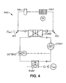
- the heat pump of the temperature control device used is an air / water type heat pump.
- the heat pump PAC illustrated on this figure 4 consists of a sealed and sealed circuit in which circulates a refrigerant in the liquid or gaseous state according to the organs through which it passes.
- a typical heat pump is a device consisting of four components: the evaporator EVAP, the compressor COMP, the condenser COND and the expander DETEND.
- the air / water type heat pump is associated, via the condenser COND, with a closed temperature control circuit in which hot water circulates for heating various elements such as a radiator RAD or a balloon. BAL hot water.
- the operating principle is as follows: the heat pump PAC takes heat from the surrounding air outside, which is at a temperature T ext , and this heat taken from the outside is transferred, through the Evaporator EVAP, to the refrigerant which vaporizes.
- the compressor COMP then sucks the vaporized refrigerant to operate a compression raising its temperature.
- the heated refrigerant gives up its heat, condensing and returning to the liquid state, the water of a temperature control circuit or directly to the air from the place to heat.
- the ambient air of the place to be heated thus has a temperature T A.
- the refrigerant then passes through the expander DETEND, which lowers the pressure of the refrigerant to thereby initiate its vaporization.
- the regulation of the heat pump device described in figure 4 is preferably made according to the temperature measured at a specific point of the device, which must be set as close as possible to a set temperature.
- T ret return water temperature
- the operating parameter defined above corresponds to the water return temperature T ret of the heat pump and the reference parameter defined above corresponds to the water return setpoint temperature T cons , ret .
- the ambient temperature T A defined above corresponds to the ambient air temperature of the room in which the radiator RAD is installed and the predetermined ambient air setpoint temperature T cons, A defined. previously corresponds to the ambient air temperature set point, for example set by the user by means of a thermostat.
- the heat pump is regulated by comparing the water return temperature T ret with respect to the water return reference temperature T consret .
- this regulation is done by ensuring that the ambient temperature T A does not deviate too much from the predetermined ambient air temperature T cons, A , by example by ensuring that the difference, in absolute value, between the ambient temperature T A and the ambient air set point temperature T cons, A does not exceed a determined comfort difference ⁇ T A.
- control method 100 it is possible to implement the control method 100 according to the present invention according to two main embodiments, a first main embodiment in which an activation period precedes a period and a second main mode in which a deactivation period precedes an activation period.
- the Figure 5A illustrates the steps of a method 100 'of optimization according to the first of these main embodiments where the activation of the heat pump of the control device precedes the deactivation of the heat pump of this device.
- the principle of such an overheating method is to increase the temperature of the temperature control circuit relative to the set point before a full hours range, to allow erasure during this last range.
- the formula (1) describes a water law setpoint modified for overheating, and the difference ⁇ T opt has a positive value.
- the steps 101'-115 'of such an overheating regulation process 100' correspond to the steps 101-115 of the general process 100 illustrated in FIG. figure 2 .
- the method 100 'of regulation by overheating is however particularly characterized in that the first mode of operation, triggered during the activation step 107', corresponds to the activation of the heat pump during a period ⁇ act , determined during the determination step 103 ', so that the temperature T ret of return of water reaches an optimum value T opt greater than a deviation ⁇ T opt with respect to the value of the water return setpoint temperature T cons , ret (t 1 ) provided at time t 1 .
- the optimum value of the water return set point temperature at time t 1 can be calculated, for example, by virtue of the return water law for the outside temperature T ext (t 1 ) estimated at the instant t 1 , which can be determined by weather forecast, for example.
- such a parameter can vary between 0 ° C (no real superheat) and a few degrees Celsius, depending on the type of installation and housing to be heated.
- the flows in the heat pump and in the heating circuit are identical. Therefore, overheating will have a significant influence on the indoor air temperature T A. In such a case, it is preferable to choose the difference ⁇ T opt taking into account the aforementioned comfort constraints, within a relatively narrow range.
- the difference ⁇ T opt can be chosen within a wider range (2.4 ° C or more), which makes it possible to lengthen by the same the available erasure time and therefore the potentially associated gain. .
- the outside temperature at 18h is often colder than the outside temperature during overheating, and if this increase is not taken into account, the temperature reached by the device may not to be quite high. It is therefore advantageous to use forecasts weather to determine the outside air temperature at 18h, and thus have a more accurate estimate of the return water temperature to reach at 18h.
- This operation overheating anticipated takes place during a period ⁇ act , then is followed by the deactivation of the heat pump, initiated during a deactivation step 111 ', for a period ⁇ dice .
- the return water temperature T ret then regularly decreases from the optimum value T opt .
- An algorithm can be used to determine the duration ⁇ act of the first period ⁇ act of overheating, and therefore the start time of the heat pump for overheating. As indicated above, this duration ⁇ act can be determined by calculating the return water temperature rise slope of the network from the starting and stopping points of the heat pump, possibly by means of a linear approximation, for example for previous cycles of temperature control.
- an automaton evaluates the time required to increase said temperature up to the value given by the modified modified return water law at time t 1 .
- the interruption of the heat pump, during a second period ⁇ dice generates a particularly effective erasure if this second period ⁇ dd covers at least partially a period during which the consumption is usually high (full hours). To ensure this, it is particularly advantageous to substantially coincide the beginning of this second period ⁇ dice with the beginning of a period of full hours.
- the forced start of the heat pump, during a first Tact period is energetically advantageous if this Tact period covers at least partially a period during which the consumption is usually low (off-peak hours). To guarantee this, it is particularly advantageous to substantially coincide the end of this period ⁇ act with the end of a period of off-peak hours.
- the Figure 5B illustrates the evolution of the return water temperature T ret with respect to the water return set point temperature T cons , ret with such a method 100 'optimization by overheating anticipated.
- the water return setpoint temperature T cons, ret depends on the indoor air setpoint temperature T cons, A set by the user of the heat pump. It is clearly seen that this water return setpoint temperature T cons, ret varies in the time during the day, depending inter alia on the surrounding outside air temperature T ext . Thus, the cooling of the outside air after 19 hours logically causes an increase in the water return setpoint temperature T cons, ret to maintain as much as possible the temperature T A of the ambient air inside the vicinity of the set room air temperature T cons, A.
- the water return temperature T ret of the heat pump is regulated around this water return setpoint temperature T cons , ret to best stall these two temperatures. This regulation is translated, in conventional mode, by a succession of cycles alternating the activation and the deactivation of the heat pump (on the Figure 5B , cycles from 11 am to 12:30 pm, from 12:30 pm to 2 pm, or from 2 pm to 3:30 pm).
- the control process 100 When it is desired to erase the consumption on a dice ⁇ time interval ranging from 17 h 45-19 h 15, which is a normal period of peak times, there may be used the control process 100 'introduced below before. In doing so, the duration of the first interval ⁇ act is calculated to be 45 minutes and this dice ⁇ interval setting overheating of the heat pump therefore ranges from 17 h to 17 h 45.
- the heat pump is activated in heating mode according to the activation step 107 ', and then deactivated from 17 h 45 to 19 h 15 according to the deactivation step 111'. After 19 h 15, the heat pump returns to a conventional control mode cycles.
- the Figure 5C illustrates, it, the evolution of the indoor air temperature T A relative to the temperature of the ambient air setpoint T cons, A set by the user of the heat pump regulated by such a method 100 anticipated overheating.
- the ambient air setpoint temperature T cons, A is set at 20.3 ° C.
- the ambient air temperature T A first oscillates around this value when the heat pump is in a conventional control mode corresponding to step 101 '.
- the heat pump When, following the activation step 107 'of the heat pump during a first period ⁇ act of approximately 17h to 17h45, the heat pump is turned on so that the return water temperature T ret reaches the optimum value T opt , the ambient air temperature T A will increase continuously.
- disabling 111 'of the heat pump then takes place during a second period during ⁇ dice longer, from approximately 17:45 to 19:30.
- the ambient temperature T A then decreases continuously, while remaining within a range ⁇ T A of acceptable temperature comfort of 1 ° C around the set temperature T cons, A.
- the principle of this first main embodiment can also be applied to another particular embodiment where the activation of the heat pump, when it is reversible, is a cooling mode in which case the value of optimum temperature T opt , to reach is less than the estimate of the water return setpoint temperature T cons, ret (t 1 ), that is to say that the difference ⁇ T opt should take a value negative, in order to compensate in anticipation the heating corresponding to the deactivation of the cooling device during the second period ⁇ dice .
- the anticipated overheating mode is particularly suitable in winter, when it is necessary to erase the consumption of the heating devices during periods of peak hours
- the anticipated cooling mode is particularly appropriate in summer, when it is necessary to erase the consumption of cooling devices at some very hot times of the day.
- the figure 6 illustrates the steps of a control method 100 "according to a second main embodiment in which the deactivation of the heat pump of the device precedes its activation, the method 100" can therefore be qualified as a delayed activation control method.
- the delayed activation control method 100 is in a sense the time symmetric of the early activation control method 100.
- the steps of such a delayed temperature activation control method 100 correspond to the steps of the general control method. optimized 100 illustrated at the figure 2 .
- the method 100 "of delayed activation control is characterized in particular in that the first operating mode MF 1 , triggered during a deactivation step 107", corresponds to the deactivation of the heat pump of the control device during a deactivation period ⁇ dd determined during the determination step 103 ", so that the operating parameter used to evaluate the regulating device reaches a value separated by a certain deviation from the estimate of a value of the reference parameter used to regulate this device.
- this difference is negative since the first heating deactivation period causes an additional lowering of temperature at time t 1 , while in the particular mode of delayed cooling control, this difference is positive. insofar as the first cooling off period causes an additional increase in temperature at time t 1 ,
- the deactivation of the heat pump of the regulating device during the period ⁇ dice is followed by the activation of the heat pump of this device during an activation step 111 "performed during a period Tact.
- the deactivation of the heat pump of the temperature control device during a first period preferably at least partially covering a period of full hours, thus allows the forced operation of the pump. to heat the device during a second period preferably at least partially covering a period of off-peak hours.
- an algorithm can be used here to determine the duration of the deactivation period ⁇ dice and therefore the start time of application of this deactivation, for example by calculation of the previous evolution slope of the operating parameter.
- this second main embodiment it is always a particular embodiment corresponding to the case where the activation of the heat pump corresponds to a heating mode.
- This particular embodiment is therefore a delayed overheating mode, to compensate for erasure during a period of peak hours, especially in winter.
- the aim is that the temperature T ret return water reaches an optimum value T opt separated from a difference .DELTA.T opt negative of the desired temperature value of return water T rec (t 1 ) planned for the moment t 1 .
- the deactivation time can then be determined by calculating the return water temperature drop slope of the network from the start and stop points of the heat pump, for example by linear approximation.
- the parameter var T then corresponds, for example, to the downward slope of the operating temperature calculated from the initial and final instants of one or more preceding cycle (s) of decrease in temperature.
- the first deactivation period ⁇ dd at least partially covers a period during which the consumption is usually high (peak hours) and the second activation period ⁇ 1 at least partially covers a period during which the consumption is usually low (off-peak hours)
- stopping the heat pump during the period ⁇ dice ie deleting in full hours, then reactivating it forcibly during the second period ⁇ act makes it possible to maintain an adequate ambient temperature while reducing consumption during peak hours.
- Such a strategy is particularly advantageous for short hours of short hours, such as for example the hollow hours meridian range from 14h to 16h. Indeed, the shorter the off-peak time range compared to the heat-up time of the heat pump of the temperature control device, the more the cooling regulation is interesting from an energy and economic point of view.
- this second main embodiment can also be applied to another particular embodiment where the activation of the heat pump, when it is reversible, is a cooling mode in which case the deviation from the optimum temperature T opt , to reach is greater than the estimate of the water return setpoint temperature T cons, ret (t 1 ), that is to say that the difference ⁇ T opt takes a value positive, in order to compensate for delayed additional heating corresponding to the deactivation of the heat pump of the device during the first period ⁇ dice .
- the optimized control method described above can be implemented by means of a regulation module.
- This module comprises, on the one hand, transmission means capable of indicating, to one or more temperature control device (s) comprising a heat pump to which it is connected, a start or end activation signal. and / or deactivation.
- Such transmission means may be wired or wireless, for example.
- This regulation module comprises, on the other hand, determination means capable of determining, for each temperature control device to be regulated, the duration of the first period ⁇ 1 defined above as a function of the operating parameters of this device. according to what has been described previously.
- determination means may comprise calculation means, such as a processor, capable of calculating the duration of the period ⁇ 1 with the formulas described above.
- such a regulation module can be integrated with the temperature control device itself. It is advantageous, in this case, for the regulation module also to comprise means for measuring the evolution of the operating parameter, in particular in order to deduce therefrom the variation parameter var T described above.
- the regulation module may comprise means for receiving measurement signals of the evolution of the operating parameter, again in order to deduce therefrom the parameter of variation. var T described previously.
- Such a remote control module can be connected to a plurality of temperature control devices, each comprising a heat pump, in order to regulate these as well independently, according to the characteristics that are specific to them, as a function of a global instruction, which is particularly advantageous for an energy operator wishing to perform a global erasure on a pool of temperature control devices with heat pumps.
- the invention also relates to a global system comprising the preceding remote control module, and a plurality of temperature control devices, each comprising a heat pump, managed by it.
- the invention also relates to a computer program comprising program code instructions for executing the steps of the above action method when said program is executed on a computer.
- the various steps of the method according to the invention are implemented by a software or computer program, this software comprising software instructions intended to be executed by a data processor of a regulation module adapted to be connected to one or more temperature control device (s) each comprising a heat pump, and being designed to control the execution of the different steps of this process.
- this software comprising software instructions intended to be executed by a data processor of a regulation module adapted to be connected to one or more temperature control device (s) each comprising a heat pump, and being designed to control the execution of the different steps of this process.
- the invention is also directed to a program that can be executed by a computer or a data processor, which program includes instructions for controlling the execution of the steps of a method as mentioned above.
- a program can use any programming language, and be in the form of source code, object code, or intermediate code between source code and object code, such as in a partially compiled form, or in n ' any other desirable form.
- the invention also relates to a data carrier readable by a computer or data processor, and comprising instructions of a program as mentioned above.
- control method described above for a single temperature control device can also be used for a set of devices of a park, to allow proper erasure and reduce the impact on the load curve on a wider scale.
- Such global regulation can be managed remotely by the operator in charge of the park.
- the different parameters ⁇ 1 , ⁇ 2 , or the time t i may be chosen differently for each device, depending on the characteristics of the associated installation such as the inertia of the building and the temperature control network. , the climatic zone, thermal power supplied by the temperature control device, etc., to allow global management of the erasure and avoid a simple shift of the peak and trough ranges on the overall load curve.
- the periods of activation and deactivation are implemented, preferably, during time intervals coinciding with the beginning of a range of full hours and off-peak hours, respectively.
- Such strict temporal coincidence is however not necessary, and there may be a time lag between the activation period and the deactivation period, knowing that the larger the offset, the less efficient the erasure will be. where the effect of inertia will lose efficiency.
- the reference time t 1 is particularly advantageous to determine the reference time t 1 as close as possible to the peak load range.
- the instant t 1 can be advanced relative to the peak load range and the erasure will be maintained longer. This principle is valid for both overheating and cooling operation.
- the above method also relates to the case where the same deactivation period would be preceded by a first activation period and followed by a second activation period, in which case it would then be necessary to determine the duration.
- the first activation period and the deactivation period on the basis of what is described above.
- the return water temperature or the water flow temperature can be used as an operating parameter, since they present the advantage of being easily measurable.
- the operating parameter may depend on a formula involving these water return and water flow temperatures (for example the weighted average of these two parameters), which makes it possible to smooth the behavior of the device.
- the invention can also be applied to an air / air type heat pump.
- the operating parameter can be either the temperature of the supply air (coming out of the pump), or the temperature of the return air (entering the pump), or depend on a formula involving these two temperatures (for example the weighted average of these two temperatures), which smooths the behavior of the pump.
Landscapes
- Engineering & Computer Science (AREA)
- Mechanical Engineering (AREA)
- Physics & Mathematics (AREA)
- General Engineering & Computer Science (AREA)
- Chemical & Material Sciences (AREA)
- Combustion & Propulsion (AREA)
- Thermal Sciences (AREA)
- Mathematical Physics (AREA)
- Signal Processing (AREA)
- Fuzzy Systems (AREA)
- General Physics & Mathematics (AREA)
- Automation & Control Theory (AREA)
- Air Conditioning Control Device (AREA)
Applications Claiming Priority (1)
| Application Number | Priority Date | Filing Date | Title |
|---|---|---|---|
| FR0959079A FR2953947B1 (fr) | 2009-12-16 | 2009-12-16 | Procede de controle optimise d'un dispositif de regulation en temperature |
Publications (2)
| Publication Number | Publication Date |
|---|---|
| EP2339255A1 true EP2339255A1 (de) | 2011-06-29 |
| EP2339255B1 EP2339255B1 (de) | 2016-08-10 |
Family
ID=42299193
Family Applications (1)
| Application Number | Title | Priority Date | Filing Date |
|---|---|---|---|
| EP10194857.8A Not-in-force EP2339255B1 (de) | 2009-12-16 | 2010-12-14 | Verfahren zur optimierten Steuerung eines Temperaturreglers |
Country Status (2)
| Country | Link |
|---|---|
| EP (1) | EP2339255B1 (de) |
| FR (1) | FR2953947B1 (de) |
Cited By (3)
| Publication number | Priority date | Publication date | Assignee | Title |
|---|---|---|---|---|
| CN105674481A (zh) * | 2015-01-06 | 2016-06-15 | 海信科龙电器股份有限公司 | 一种空气调节系统 |
| CN110736243A (zh) * | 2019-10-29 | 2020-01-31 | 珠海格力电器股份有限公司 | 空调及温度调节器的控制方法和装置 |
| CN114484935A (zh) * | 2021-12-31 | 2022-05-13 | 青岛海尔空调电子有限公司 | 热泵机组及其控制方法和控制装置 |
Families Citing this family (3)
| Publication number | Priority date | Publication date | Assignee | Title |
|---|---|---|---|---|
| FR3025871B1 (fr) | 2014-09-16 | 2019-10-04 | Better Watt | Equipement de controle d'au moins un appareil de regulation thermique, et ensemble de regulation et systeme de pilotage associes |
| CN108386979B (zh) * | 2018-02-28 | 2020-07-24 | 海信(山东)空调有限公司 | 一种空调器的控制方法及装置 |
| CN113557393B (zh) * | 2019-03-05 | 2022-08-02 | 亿可能源科技(上海)有限公司 | 空调系统的管理方法、控制方法及系统、存储介质 |
Citations (5)
| Publication number | Priority date | Publication date | Assignee | Title |
|---|---|---|---|---|
| GB2278207A (en) * | 1993-05-17 | 1994-11-23 | Ea Tech Ltd | Heating control apparatus |
| EP0688085A1 (de) * | 1994-06-17 | 1995-12-20 | Schlumberger Industries S.A. | System zur Temperaturregelung mit Optimierung bei Tarif-Umschaltung |
| FR2793643A1 (fr) * | 1999-05-12 | 2000-11-17 | Delta Dore | Appareil de commande d'une installation electrique de chauffage d'une habitation particuliere |
| US20050005621A1 (en) * | 2003-07-10 | 2005-01-13 | Jayadev Tumkur S. | Strategic-response control system for regulating air conditioners for economic operation |
| FR2866944A1 (fr) * | 2004-03-01 | 2005-09-02 | Florence Tantot | Systeme de commande d'equipements de conditionnement d'ambiance avec optimisation energetique |
-
2009
- 2009-12-16 FR FR0959079A patent/FR2953947B1/fr not_active Expired - Fee Related
-
2010
- 2010-12-14 EP EP10194857.8A patent/EP2339255B1/de not_active Not-in-force
Patent Citations (5)
| Publication number | Priority date | Publication date | Assignee | Title |
|---|---|---|---|---|
| GB2278207A (en) * | 1993-05-17 | 1994-11-23 | Ea Tech Ltd | Heating control apparatus |
| EP0688085A1 (de) * | 1994-06-17 | 1995-12-20 | Schlumberger Industries S.A. | System zur Temperaturregelung mit Optimierung bei Tarif-Umschaltung |
| FR2793643A1 (fr) * | 1999-05-12 | 2000-11-17 | Delta Dore | Appareil de commande d'une installation electrique de chauffage d'une habitation particuliere |
| US20050005621A1 (en) * | 2003-07-10 | 2005-01-13 | Jayadev Tumkur S. | Strategic-response control system for regulating air conditioners for economic operation |
| FR2866944A1 (fr) * | 2004-03-01 | 2005-09-02 | Florence Tantot | Systeme de commande d'equipements de conditionnement d'ambiance avec optimisation energetique |
Cited By (4)
| Publication number | Priority date | Publication date | Assignee | Title |
|---|---|---|---|---|
| CN105674481A (zh) * | 2015-01-06 | 2016-06-15 | 海信科龙电器股份有限公司 | 一种空气调节系统 |
| CN110736243A (zh) * | 2019-10-29 | 2020-01-31 | 珠海格力电器股份有限公司 | 空调及温度调节器的控制方法和装置 |
| CN114484935A (zh) * | 2021-12-31 | 2022-05-13 | 青岛海尔空调电子有限公司 | 热泵机组及其控制方法和控制装置 |
| CN114484935B (zh) * | 2021-12-31 | 2023-09-26 | 青岛海尔空调电子有限公司 | 热泵机组及其控制方法和控制装置 |
Also Published As
| Publication number | Publication date |
|---|---|
| FR2953947B1 (fr) | 2012-08-31 |
| EP2339255B1 (de) | 2016-08-10 |
| FR2953947A1 (fr) | 2011-06-17 |
Similar Documents
| Publication | Publication Date | Title |
|---|---|---|
| EP2339255B1 (de) | Verfahren zur optimierten Steuerung eines Temperaturreglers | |
| WO2007063119A1 (fr) | Unite solaire de production frigorifique pour installation de climatisation, unite solaire de production calorifique, dispositifs et procede de controle correspondants | |
| FR2954462A1 (fr) | Optimisation d'une capacite de chauffage globale d'un systeme de climatisation | |
| FR2964727A1 (fr) | Systeme thermique a faible puissance pour l'habitat | |
| EP3428858B1 (de) | Optimierungsvorrichtung für die benutzung einer verfügbaren erneuerbaren energie | |
| FR2983354A1 (fr) | Procede de regulation de la temperature d'une batterie de traction d'un vehicule electrique en charge, en particulier lors d'une charge rapide de la batterie | |
| WO2015158782A1 (fr) | Système de chauffe-eau à consommation énergétique modulable | |
| FR2466713A1 (fr) | Commande par microprocesseur de chauffage supplementaire avec reduction de la valeur de reglage de nuit | |
| EP3172499B1 (de) | Kälteerzeugungsvorrichtung mit mittel zur gleichzeitigen kondensation durch luft und verfahren zur implementierung dieser einrichtung | |
| FR3039462A1 (fr) | Dispositif de chauffage et procede de gestion associe | |
| FR2997233A1 (fr) | Gestion de batterie d'un vehicule non branche a une source d'energie externe | |
| CN113834219B (zh) | 热水器的加热控制方法、控制装置及热水器 | |
| EP4308861A1 (de) | Verfahren zur steuerung einer an eine geothermische quelle angeschlossenen anlage zur versorgung mindestens eines gebäudes sowie regelsystem und anlage hierzu | |
| EP3258187B1 (de) | Verfahren zur änderung des energieverbrauchs eines geräts | |
| FR2966565A1 (fr) | Installation de production d’eau chaude sanitaire pour habitation collective et procede de mise en oeuvre d’une telle installation | |
| FR3104239A1 (fr) | système pilotant un dispositif de renouvellement d’air d’une zone et un dispositif de chauffage de la zone | |
| EP3581853B1 (de) | Wärmeübertragungsmodul für die erzeugung von warmwasser | |
| FR2674010A1 (fr) | Procede pour enclencher le degivrage d'un echangeur thermique. | |
| FR3028929B1 (fr) | Machine a absorption a coefficient de performance optimise | |
| EP4124803A1 (de) | Steuerverfahren eines thermodynamischen speicher- und heizsystems | |
| JP4515282B2 (ja) | 氷蓄熱槽の水量調整方法 | |
| FR3132564A1 (fr) | Procédé de commande du fonctionnement d’une thermofrigopompe | |
| WO2014053988A1 (fr) | Procede predictif de commande par exemple du chauffage et dispositif pour la mise en œuvre du procede | |
| FR3015653A1 (fr) | Systeme de pompe a chaleur regulable en puissance | |
| FR3034178A1 (fr) | Dispositif de chauffage de l'eau dans une cuve d'un chauffe-eau |
Legal Events
| Date | Code | Title | Description |
|---|---|---|---|
| PUAI | Public reference made under article 153(3) epc to a published international application that has entered the european phase |
Free format text: ORIGINAL CODE: 0009012 |
|
| AK | Designated contracting states |
Kind code of ref document: A1 Designated state(s): AL AT BE BG CH CY CZ DE DK EE ES FI FR GB GR HR HU IE IS IT LI LT LU LV MC MK MT NL NO PL PT RO RS SE SI SK SM TR |
|
| AX | Request for extension of the european patent |
Extension state: BA ME |
|
| 17P | Request for examination filed |
Effective date: 20110808 |
|
| 17Q | First examination report despatched |
Effective date: 20120921 |
|
| GRAP | Despatch of communication of intention to grant a patent |
Free format text: ORIGINAL CODE: EPIDOSNIGR1 |
|
| INTG | Intention to grant announced |
Effective date: 20160226 |
|
| GRAS | Grant fee paid |
Free format text: ORIGINAL CODE: EPIDOSNIGR3 |
|
| GRAA | (expected) grant |
Free format text: ORIGINAL CODE: 0009210 |
|
| AK | Designated contracting states |
Kind code of ref document: B1 Designated state(s): AL AT BE BG CH CY CZ DE DK EE ES FI FR GB GR HR HU IE IS IT LI LT LU LV MC MK MT NL NO PL PT RO RS SE SI SK SM TR |
|
| REG | Reference to a national code |
Ref country code: GB Ref legal event code: FG4D Free format text: NOT ENGLISH |
|
| REG | Reference to a national code |
Ref country code: CH Ref legal event code: EP Ref country code: AT Ref legal event code: REF Ref document number: 819419 Country of ref document: AT Kind code of ref document: T Effective date: 20160815 |
|
| REG | Reference to a national code |
Ref country code: IE Ref legal event code: FG4D Free format text: LANGUAGE OF EP DOCUMENT: FRENCH |
|
| REG | Reference to a national code |
Ref country code: DE Ref legal event code: R096 Ref document number: 602010035308 Country of ref document: DE |
|
| REG | Reference to a national code |
Ref country code: LT Ref legal event code: MG4D |
|
| REG | Reference to a national code |
Ref country code: NL Ref legal event code: MP Effective date: 20160810 |
|
| REG | Reference to a national code |
Ref country code: FR Ref legal event code: PLFP Year of fee payment: 7 |
|
| REG | Reference to a national code |
Ref country code: AT Ref legal event code: MK05 Ref document number: 819419 Country of ref document: AT Kind code of ref document: T Effective date: 20160810 |
|
| PG25 | Lapsed in a contracting state [announced via postgrant information from national office to epo] |
Ref country code: NO Free format text: LAPSE BECAUSE OF FAILURE TO SUBMIT A TRANSLATION OF THE DESCRIPTION OR TO PAY THE FEE WITHIN THE PRESCRIBED TIME-LIMIT Effective date: 20161110 Ref country code: NL Free format text: LAPSE BECAUSE OF FAILURE TO SUBMIT A TRANSLATION OF THE DESCRIPTION OR TO PAY THE FEE WITHIN THE PRESCRIBED TIME-LIMIT Effective date: 20160810 Ref country code: LT Free format text: LAPSE BECAUSE OF FAILURE TO SUBMIT A TRANSLATION OF THE DESCRIPTION OR TO PAY THE FEE WITHIN THE PRESCRIBED TIME-LIMIT Effective date: 20160810 Ref country code: FI Free format text: LAPSE BECAUSE OF FAILURE TO SUBMIT A TRANSLATION OF THE DESCRIPTION OR TO PAY THE FEE WITHIN THE PRESCRIBED TIME-LIMIT Effective date: 20160810 Ref country code: IS Free format text: LAPSE BECAUSE OF FAILURE TO SUBMIT A TRANSLATION OF THE DESCRIPTION OR TO PAY THE FEE WITHIN THE PRESCRIBED TIME-LIMIT Effective date: 20161210 Ref country code: IT Free format text: LAPSE BECAUSE OF FAILURE TO SUBMIT A TRANSLATION OF THE DESCRIPTION OR TO PAY THE FEE WITHIN THE PRESCRIBED TIME-LIMIT Effective date: 20160810 Ref country code: HR Free format text: LAPSE BECAUSE OF FAILURE TO SUBMIT A TRANSLATION OF THE DESCRIPTION OR TO PAY THE FEE WITHIN THE PRESCRIBED TIME-LIMIT Effective date: 20160810 Ref country code: RS Free format text: LAPSE BECAUSE OF FAILURE TO SUBMIT A TRANSLATION OF THE DESCRIPTION OR TO PAY THE FEE WITHIN THE PRESCRIBED TIME-LIMIT Effective date: 20160810 |
|
| PG25 | Lapsed in a contracting state [announced via postgrant information from national office to epo] |
Ref country code: SE Free format text: LAPSE BECAUSE OF FAILURE TO SUBMIT A TRANSLATION OF THE DESCRIPTION OR TO PAY THE FEE WITHIN THE PRESCRIBED TIME-LIMIT Effective date: 20160810 Ref country code: AT Free format text: LAPSE BECAUSE OF FAILURE TO SUBMIT A TRANSLATION OF THE DESCRIPTION OR TO PAY THE FEE WITHIN THE PRESCRIBED TIME-LIMIT Effective date: 20160810 Ref country code: LV Free format text: LAPSE BECAUSE OF FAILURE TO SUBMIT A TRANSLATION OF THE DESCRIPTION OR TO PAY THE FEE WITHIN THE PRESCRIBED TIME-LIMIT Effective date: 20160810 Ref country code: PL Free format text: LAPSE BECAUSE OF FAILURE TO SUBMIT A TRANSLATION OF THE DESCRIPTION OR TO PAY THE FEE WITHIN THE PRESCRIBED TIME-LIMIT Effective date: 20160810 Ref country code: ES Free format text: LAPSE BECAUSE OF FAILURE TO SUBMIT A TRANSLATION OF THE DESCRIPTION OR TO PAY THE FEE WITHIN THE PRESCRIBED TIME-LIMIT Effective date: 20160810 Ref country code: PT Free format text: LAPSE BECAUSE OF FAILURE TO SUBMIT A TRANSLATION OF THE DESCRIPTION OR TO PAY THE FEE WITHIN THE PRESCRIBED TIME-LIMIT Effective date: 20161212 Ref country code: GR Free format text: LAPSE BECAUSE OF FAILURE TO SUBMIT A TRANSLATION OF THE DESCRIPTION OR TO PAY THE FEE WITHIN THE PRESCRIBED TIME-LIMIT Effective date: 20161111 |
|
| PG25 | Lapsed in a contracting state [announced via postgrant information from national office to epo] |
Ref country code: EE Free format text: LAPSE BECAUSE OF FAILURE TO SUBMIT A TRANSLATION OF THE DESCRIPTION OR TO PAY THE FEE WITHIN THE PRESCRIBED TIME-LIMIT Effective date: 20160810 Ref country code: RO Free format text: LAPSE BECAUSE OF FAILURE TO SUBMIT A TRANSLATION OF THE DESCRIPTION OR TO PAY THE FEE WITHIN THE PRESCRIBED TIME-LIMIT Effective date: 20160810 |
|
| REG | Reference to a national code |
Ref country code: DE Ref legal event code: R097 Ref document number: 602010035308 Country of ref document: DE |
|
| PG25 | Lapsed in a contracting state [announced via postgrant information from national office to epo] |
Ref country code: CZ Free format text: LAPSE BECAUSE OF FAILURE TO SUBMIT A TRANSLATION OF THE DESCRIPTION OR TO PAY THE FEE WITHIN THE PRESCRIBED TIME-LIMIT Effective date: 20160810 Ref country code: SM Free format text: LAPSE BECAUSE OF FAILURE TO SUBMIT A TRANSLATION OF THE DESCRIPTION OR TO PAY THE FEE WITHIN THE PRESCRIBED TIME-LIMIT Effective date: 20160810 Ref country code: SK Free format text: LAPSE BECAUSE OF FAILURE TO SUBMIT A TRANSLATION OF THE DESCRIPTION OR TO PAY THE FEE WITHIN THE PRESCRIBED TIME-LIMIT Effective date: 20160810 Ref country code: DK Free format text: LAPSE BECAUSE OF FAILURE TO SUBMIT A TRANSLATION OF THE DESCRIPTION OR TO PAY THE FEE WITHIN THE PRESCRIBED TIME-LIMIT Effective date: 20160810 Ref country code: BE Free format text: LAPSE BECAUSE OF NON-PAYMENT OF DUE FEES Effective date: 20161231 Ref country code: BG Free format text: LAPSE BECAUSE OF FAILURE TO SUBMIT A TRANSLATION OF THE DESCRIPTION OR TO PAY THE FEE WITHIN THE PRESCRIBED TIME-LIMIT Effective date: 20161110 |
|
| PLBE | No opposition filed within time limit |
Free format text: ORIGINAL CODE: 0009261 |
|
| STAA | Information on the status of an ep patent application or granted ep patent |
Free format text: STATUS: NO OPPOSITION FILED WITHIN TIME LIMIT |
|
| REG | Reference to a national code |
Ref country code: DE Ref legal event code: R119 Ref document number: 602010035308 Country of ref document: DE |
|
| 26N | No opposition filed |
Effective date: 20170511 |
|
| REG | Reference to a national code |
Ref country code: CH Ref legal event code: PL |
|
| GBPC | Gb: european patent ceased through non-payment of renewal fee |
Effective date: 20161214 |
|
| PG25 | Lapsed in a contracting state [announced via postgrant information from national office to epo] |
Ref country code: SI Free format text: LAPSE BECAUSE OF FAILURE TO SUBMIT A TRANSLATION OF THE DESCRIPTION OR TO PAY THE FEE WITHIN THE PRESCRIBED TIME-LIMIT Effective date: 20160810 |
|
| PG25 | Lapsed in a contracting state [announced via postgrant information from national office to epo] |
Ref country code: MC Free format text: LAPSE BECAUSE OF FAILURE TO SUBMIT A TRANSLATION OF THE DESCRIPTION OR TO PAY THE FEE WITHIN THE PRESCRIBED TIME-LIMIT Effective date: 20160810 |
|
| REG | Reference to a national code |
Ref country code: IE Ref legal event code: MM4A |
|
| PG25 | Lapsed in a contracting state [announced via postgrant information from national office to epo] |
Ref country code: LI Free format text: LAPSE BECAUSE OF NON-PAYMENT OF DUE FEES Effective date: 20161231 Ref country code: CH Free format text: LAPSE BECAUSE OF NON-PAYMENT OF DUE FEES Effective date: 20161231 Ref country code: LU Free format text: LAPSE BECAUSE OF NON-PAYMENT OF DUE FEES Effective date: 20161214 |
|
| PG25 | Lapsed in a contracting state [announced via postgrant information from national office to epo] |
Ref country code: GB Free format text: LAPSE BECAUSE OF NON-PAYMENT OF DUE FEES Effective date: 20161214 Ref country code: DE Free format text: LAPSE BECAUSE OF NON-PAYMENT OF DUE FEES Effective date: 20170701 Ref country code: IE Free format text: LAPSE BECAUSE OF NON-PAYMENT OF DUE FEES Effective date: 20161214 |
|
| REG | Reference to a national code |
Ref country code: FR Ref legal event code: PLFP Year of fee payment: 8 |
|
| REG | Reference to a national code |
Ref country code: BE Ref legal event code: MM Effective date: 20161231 |
|
| PG25 | Lapsed in a contracting state [announced via postgrant information from national office to epo] |
Ref country code: CY Free format text: LAPSE BECAUSE OF FAILURE TO SUBMIT A TRANSLATION OF THE DESCRIPTION OR TO PAY THE FEE WITHIN THE PRESCRIBED TIME-LIMIT Effective date: 20160810 Ref country code: HU Free format text: LAPSE BECAUSE OF FAILURE TO SUBMIT A TRANSLATION OF THE DESCRIPTION OR TO PAY THE FEE WITHIN THE PRESCRIBED TIME-LIMIT; INVALID AB INITIO Effective date: 20101214 |
|
| PG25 | Lapsed in a contracting state [announced via postgrant information from national office to epo] |
Ref country code: TR Free format text: LAPSE BECAUSE OF FAILURE TO SUBMIT A TRANSLATION OF THE DESCRIPTION OR TO PAY THE FEE WITHIN THE PRESCRIBED TIME-LIMIT Effective date: 20160810 Ref country code: MK Free format text: LAPSE BECAUSE OF FAILURE TO SUBMIT A TRANSLATION OF THE DESCRIPTION OR TO PAY THE FEE WITHIN THE PRESCRIBED TIME-LIMIT Effective date: 20160810 |
|
| PG25 | Lapsed in a contracting state [announced via postgrant information from national office to epo] |
Ref country code: MT Free format text: LAPSE BECAUSE OF FAILURE TO SUBMIT A TRANSLATION OF THE DESCRIPTION OR TO PAY THE FEE WITHIN THE PRESCRIBED TIME-LIMIT Effective date: 20160810 |
|
| PG25 | Lapsed in a contracting state [announced via postgrant information from national office to epo] |
Ref country code: AL Free format text: LAPSE BECAUSE OF FAILURE TO SUBMIT A TRANSLATION OF THE DESCRIPTION OR TO PAY THE FEE WITHIN THE PRESCRIBED TIME-LIMIT Effective date: 20160810 |
|
| PGFP | Annual fee paid to national office [announced via postgrant information from national office to epo] |
Ref country code: FR Payment date: 20211130 Year of fee payment: 12 |
|
| PG25 | Lapsed in a contracting state [announced via postgrant information from national office to epo] |
Ref country code: FR Free format text: LAPSE BECAUSE OF NON-PAYMENT OF DUE FEES Effective date: 20221231 |