EP2338213B1 - Pose de câbles de réseau dans des canalisations d adduction d eau - Google Patents
Pose de câbles de réseau dans des canalisations d adduction d eau Download PDFInfo
- Publication number
- EP2338213B1 EP2338213B1 EP09785627.2A EP09785627A EP2338213B1 EP 2338213 B1 EP2338213 B1 EP 2338213B1 EP 09785627 A EP09785627 A EP 09785627A EP 2338213 B1 EP2338213 B1 EP 2338213B1
- Authority
- EP
- European Patent Office
- Prior art keywords
- cable
- sewer
- existing pipe
- arm
- junction
- Prior art date
- Legal status (The legal status is an assumption and is not a legal conclusion. Google has not performed a legal analysis and makes no representation as to the accuracy of the status listed.)
- Not-in-force
Links
- XLYOFNOQVPJJNP-UHFFFAOYSA-N water Substances O XLYOFNOQVPJJNP-UHFFFAOYSA-N 0.000 title claims description 39
- 238000000034 method Methods 0.000 claims description 46
- 238000007789 sealing Methods 0.000 claims description 19
- 239000007789 gas Substances 0.000 claims description 7
- 230000001473 noxious effect Effects 0.000 claims description 3
- 239000010865 sewage Substances 0.000 claims description 3
- 239000002351 wastewater Substances 0.000 claims description 3
- 239000000835 fiber Substances 0.000 description 14
- 239000000853 adhesive Substances 0.000 description 7
- 230000001070 adhesive effect Effects 0.000 description 7
- 230000000052 comparative effect Effects 0.000 description 7
- 238000005188 flotation Methods 0.000 description 5
- 239000000463 material Substances 0.000 description 5
- 239000013307 optical fiber Substances 0.000 description 5
- 230000006835 compression Effects 0.000 description 4
- 238000007906 compression Methods 0.000 description 4
- 239000010410 layer Substances 0.000 description 4
- 239000011248 coating agent Substances 0.000 description 3
- 238000000576 coating method Methods 0.000 description 3
- 230000008878 coupling Effects 0.000 description 3
- 238000010168 coupling process Methods 0.000 description 3
- 238000005859 coupling reaction Methods 0.000 description 3
- 239000003822 epoxy resin Substances 0.000 description 3
- 239000002184 metal Substances 0.000 description 3
- 230000003287 optical effect Effects 0.000 description 3
- 229920000647 polyepoxide Polymers 0.000 description 3
- 239000012858 resilient material Substances 0.000 description 3
- 230000000717 retained effect Effects 0.000 description 3
- 239000004576 sand Substances 0.000 description 3
- 239000010426 asphalt Substances 0.000 description 2
- 229920001903 high density polyethylene Polymers 0.000 description 2
- 239000004700 high-density polyethylene Substances 0.000 description 2
- 230000006978 adaptation Effects 0.000 description 1
- 238000009412 basement excavation Methods 0.000 description 1
- 230000005540 biological transmission Effects 0.000 description 1
- 230000015572 biosynthetic process Effects 0.000 description 1
- 239000000919 ceramic Substances 0.000 description 1
- 239000003086 colorant Substances 0.000 description 1
- 238000004891 communication Methods 0.000 description 1
- 238000010276 construction Methods 0.000 description 1
- 239000012792 core layer Substances 0.000 description 1
- 230000000694 effects Effects 0.000 description 1
- 239000012530 fluid Substances 0.000 description 1
- 230000001939 inductive effect Effects 0.000 description 1
- 230000004048 modification Effects 0.000 description 1
- 238000012986 modification Methods 0.000 description 1
- 210000002445 nipple Anatomy 0.000 description 1
- 239000004033 plastic Substances 0.000 description 1
- 229920003023 plastic Polymers 0.000 description 1
- 238000009428 plumbing Methods 0.000 description 1
- 230000000135 prohibitive effect Effects 0.000 description 1
- 239000000126 substance Substances 0.000 description 1
- 230000007704 transition Effects 0.000 description 1
Images


Classifications
-
- G—PHYSICS
- G02—OPTICS
- G02B—OPTICAL ELEMENTS, SYSTEMS OR APPARATUS
- G02B6/00—Light guides; Structural details of arrangements comprising light guides and other optical elements, e.g. couplings
- G02B6/46—Processes or apparatus adapted for installing or repairing optical fibres or optical cables
- G02B6/47—Installation in buildings
- G02B6/475—Mechanical aspects of installing cables in ducts or the like for buildings
-
- H—ELECTRICITY
- H02—GENERATION; CONVERSION OR DISTRIBUTION OF ELECTRIC POWER
- H02G—INSTALLATION OF ELECTRIC CABLES OR LINES, OR OF COMBINED OPTICAL AND ELECTRIC CABLES OR LINES
- H02G1/00—Methods or apparatus specially adapted for installing, maintaining, repairing or dismantling electric cables or lines
- H02G1/06—Methods or apparatus specially adapted for installing, maintaining, repairing or dismantling electric cables or lines for laying cables, e.g. laying apparatus on vehicle
- H02G1/08—Methods or apparatus specially adapted for installing, maintaining, repairing or dismantling electric cables or lines for laying cables, e.g. laying apparatus on vehicle through tubing or conduit, e.g. rod or draw wire for pushing or pulling
- H02G1/086—Methods or apparatus specially adapted for installing, maintaining, repairing or dismantling electric cables or lines for laying cables, e.g. laying apparatus on vehicle through tubing or conduit, e.g. rod or draw wire for pushing or pulling using fluid as pulling means, e.g. liquid, pressurised gas or suction means
-
- G—PHYSICS
- G02—OPTICS
- G02B—OPTICAL ELEMENTS, SYSTEMS OR APPARATUS
- G02B6/00—Light guides; Structural details of arrangements comprising light guides and other optical elements, e.g. couplings
- G02B6/46—Processes or apparatus adapted for installing or repairing optical fibres or optical cables
- G02B6/50—Underground or underwater installation; Installation through tubing, conduits or ducts
-
- H—ELECTRICITY
- H02—GENERATION; CONVERSION OR DISTRIBUTION OF ELECTRIC POWER
- H02G—INSTALLATION OF ELECTRIC CABLES OR LINES, OR OF COMBINED OPTICAL AND ELECTRIC CABLES OR LINES
- H02G1/00—Methods or apparatus specially adapted for installing, maintaining, repairing or dismantling electric cables or lines
- H02G1/06—Methods or apparatus specially adapted for installing, maintaining, repairing or dismantling electric cables or lines for laying cables, e.g. laying apparatus on vehicle
- H02G1/08—Methods or apparatus specially adapted for installing, maintaining, repairing or dismantling electric cables or lines for laying cables, e.g. laying apparatus on vehicle through tubing or conduit, e.g. rod or draw wire for pushing or pulling
-
- H—ELECTRICITY
- H02—GENERATION; CONVERSION OR DISTRIBUTION OF ELECTRIC POWER
- H02G—INSTALLATION OF ELECTRIC CABLES OR LINES, OR OF COMBINED OPTICAL AND ELECTRIC CABLES OR LINES
- H02G9/00—Installations of electric cables or lines in or on the ground or water
- H02G9/06—Installations of electric cables or lines in or on the ground or water in underground tubes or conduits; Tubes or conduits therefor
-
- Y—GENERAL TAGGING OF NEW TECHNOLOGICAL DEVELOPMENTS; GENERAL TAGGING OF CROSS-SECTIONAL TECHNOLOGIES SPANNING OVER SEVERAL SECTIONS OF THE IPC; TECHNICAL SUBJECTS COVERED BY FORMER USPC CROSS-REFERENCE ART COLLECTIONS [XRACs] AND DIGESTS
- Y10—TECHNICAL SUBJECTS COVERED BY FORMER USPC
- Y10T—TECHNICAL SUBJECTS COVERED BY FORMER US CLASSIFICATION
- Y10T29/00—Metal working
- Y10T29/49—Method of mechanical manufacture
- Y10T29/49002—Electrical device making
- Y10T29/49117—Conductor or circuit manufacturing
- Y10T29/49169—Assembling electrical component directly to terminal or elongated conductor
-
- Y—GENERAL TAGGING OF NEW TECHNOLOGICAL DEVELOPMENTS; GENERAL TAGGING OF CROSS-SECTIONAL TECHNOLOGIES SPANNING OVER SEVERAL SECTIONS OF THE IPC; TECHNICAL SUBJECTS COVERED BY FORMER USPC CROSS-REFERENCE ART COLLECTIONS [XRACs] AND DIGESTS
- Y10—TECHNICAL SUBJECTS COVERED BY FORMER USPC
- Y10T—TECHNICAL SUBJECTS COVERED BY FORMER US CLASSIFICATION
- Y10T29/00—Metal working
- Y10T29/53—Means to assemble or disassemble
- Y10T29/5367—Coupling to conduit
Definitions
- the present invention relates to the laying of cables in water supply pipes.
- a dedicated conduit may be required. In some locations this distance may be relatively short, for instance in city centres and thus fitting a dedicated conduit is relatively low in cost and low in disruption. In other locations this distance may be longer or may cross private property. In such locations, the cost of providing a conduit and/or the disruption caused by digging up the private property to lay the conduit may be prohibitive. For instance in many suburban locations connection to a cable television network requires a cable conduit to be laid across a homeowner's front garden from a trunk cable running along or alongside the public roadway. This can require the digging of a trench through the garden which may be sufficiently expensive and/or unsightly to dissuade the homeowner from ordering a connection to the network.
- DE19734274 (A1 ) discloses a network having optical waveguides between subscribers and communication centres in existing supply lines for fluid media e.g water, sewage gas or heat.
- the waveguides are fed into the supply lines via conduits.
- the waveguides have a coating to protect against the effect of the medium used in the supply lines.
- Individual waveguides may be inserted into the supply lines and several individual waveguides may be combined into a connecting waveguide.
- the conduit unit may have a removable stopper with openings for the waveguides. The openings have gas and water tight seals.
- US6584252 (B1 ) discloses a method for providing fibre optic cable to an end user including disposing the fibre optic cable having first and second ends within a sewer line coupled to a premises of the end user, and coupling the first end of the fibre optic cable to a network interface device inside the premises.
- the method may further include disposing an optical splitter within a main sewer line coupled to the sewer line and coupling the second end of the fibre optic cable to the optical splitter.
- WO0192921 A1 discloses deploying a fiber optic network through a water distribution system by creating an access point in a water pipe and positioning a cable spool in close proximity to the entry point before a capture device is then inserted into the exit point in the water pipeline, a flotation device is attached to the front end of the cable to be deployed and the flotation device is inserted into the water pipeline through the entry point.
- this document relies on the water current in the water pipeline to unspool the cable and carry the flotation device and fiber cable toward the exit point, at which the capture device captures the flotation device or the cable itself. The flotation device, along with the attached fiber cable, is then pulled through the exit point of the water pipeline.
- US2002114595 (A1 ) describes a method of laying fibre optic cables that involves modifying two segments of a pipe to provide entry and exit points for a data conduit. Modification of the pipe entails bisecting the pipe and inserting a wye-fitting between the resulting two sections.
- the wye-fitting may be the type commonly used in plumbing to attach a branch pipe to a main pipe. After the addition of the wye-fitting, the data conduit is introduced into the pipe, through a coupling inserted into the third leg of the wye-fitting.
- DE 31 40 928 A1 discloses a method for pulling telecommunications cables into supply lines, in which the free end of the cable is inserted into the tube through a connecting piece, is drawn through the tube as far as the outlet point by means of a driving body, using the flow pressure of the water, and is passed out through a further connecting piece.
- a tubular piece of the supply line is removed and replaced with a piece provided with a connecting piece which encloses an oblique angle of approximately 120 DEG to 160 DEG with the tube axis in the direction in which the cable is inserted and pulled through, and in that the special tubular piece is connected on both sides to the ends of the supply line.
- US 2003 068143A1 discloses a method and apparatus for providing fiber optic cables through gas service pipes wherein a flexible tube is disposed inside a gas
- a fiber optic cable is disposed through the inside of the tube, with each end of the cable outside the service pipe.
- a first nipple is joined to the service pipe at a first location convenient for connecting fiber optic cable to the building and provides a pass way between the inside and the outside of the pipe.
- a branch cable can pass from a trunk cable to a node location without providing a dedicated conduit.
- the method may further comprise the steps of connecting the branch cable to the trunk cable and/or connecting the branch cable to the node.
- the branch cable may be connected directly to the trunk cable or may be connected via suitable junction box.
- the branch cable may enter the water supply pipe adjacent to the junction box.
- the branch cable may travel along a suitable conduit such as a microtrench or other conventional conduit between the junction box and the pre-existing pipe.
- the branch cable may be connected directly to suitable equipment at the node or may be connected to a junction box or socket allowing one or more devices to be connected to the network.
- the cable may be removed from the pre-existing pipe adjacent to a building within which the node is provided. In such embodiments, the cable may then be passed through a suitable entry passageway to be connected to the node within the building. Additionally or alternatively, the cable may be removed from the pre-existing pipe within a building within which the node is provided. The cable may enter and leave the pre-existing pipe between a mains side stopcock and a dedicated building stopcock.
- the method includes the steps of providing a cable transfer means enabling a cable to be introduced to or removed from said pre-existing pipe.
- the cable transfer means comprise a Y-junction inserted into a gap provided in the pre-existing pipe.
- the leg and one arm of the Y-junction are open and have an open end adapted to be connected to the pre-existing pipe thereby providing a water flow path through the Y-junction.
- the open arm and the leg of the Y-junction may be provided in along a common linear axis.
- the other arm has a cable passage provided therethrough, wherein the cable is threaded along a microduct tube, wherein the other arm is of considerably narrower diameter than the open arm and the leg such that it tightly encloses the cable passage in the form of a duct adapted to fit around the microduct tube.
- the diameter of the passage may be matched to the expected microduct tube diameter. In such cases the diameter of the passage may be selected to be equal to or less than the expected diameter of the microduct tube, such that when deformed a watertight seal is maintained.
- the cable passage may be adapted to allow the passage of a bundle of microduct tubes.
- the open leg and arm of the Y-junction may be connected to the pre-existing pipe via suitable fittings.
- the fitting is preferably adapted to seal the Y-junction to the pre-existing pipe.
- the fitting may be a push fitting or a compression fitting and in particular may be a BSP or metric compression fitting.
- the method may incorporate the steps of forming a suitable gap in the pre-existing pipe.
- the gap may be formed by use of suitable cutting equipment.
- the method may incorporate the step of prior to forming the gap, turning off the water supply to the pre-existing pipe. This can make fitting the Y-junction simpler and minimise the water leakage and disruption caused by fitting the Y-junction.
- the Y-junction may be formed from any suitable material. Typically it may be formed from a suitable metal, plastic or ceramic substance.
- the cable may be any suitable form of cable.
- the cable is preferably provided with a suitable insulating coating.
- the cable may be an optical fibre.
- the fibre may have a single core or multiple cores. In one preferred embodiment the fibre may have 2-4 cores.
- the trunk cable may be laid in a dedicated conduit or may be laid along a sewer.
- the trunk cable may be laid according to the disclosure of our copending application WO2008/009969 .
- a method of laying a cable between two points comprising the steps of: laying a cable through one or more lengths of sewer between the two points; and where there is no convenient length of sewer or a gap between convenient lengths of sewer, providing a length of dedicated cable conduit between said lengths of sewer and laying said cable through said dedicated cable conduit.
- cables may be laid along water supply pipes, roadside drains, storm drains or similar.
- the cable may be laid through the sewer using any suitable technique.
- the techniques may include, but are not limited to: laying the cable loose in the flow channel of the sewer; pinning the cable to the walls of the sewer; or passing the cable through a duct provided in the sewer.
- the method may include the step of installing a suitable cable guide at points wherein the cable is desired or required to enter or leave the flow channel.
- the cable guide is preferably adapted to enable the cable to enter/exit the flow channel without significantly impeding the flow.
- the cable guide may comprise a body section and an arm section, the body section adapted to lie substantially flush with the wall of the flow channel and the arm section providing a passage for the cable between the flow channel and a point outside the flow channel.
- Such cable guides may be installed at points wherein the cable is required to enter or leave the sewer and on either side of points such as junctions or bends in the sewer wherein a cable in the flow channel is likely to lie across the direction of flow. In such areas, the cable may be laid outside the flow channel using any suitable other technique such as pinning the cable to the walls of the sewer; or passing the cable through a duct provided in the sewer.
- the method may involve the additional step of installing a suitable duct.
- the duct may be pre-installed in the sewer at the time of constructing the sewer.
- the duct may be pinned or otherwise affixed to the walls or ceiling of the sewer.
- the duct may be substantially continuous between the cable entry point and the cable exit point or may be comprised of a plurality of separate sections having gaps therebetween.
- the cable conduit may be provided by any suitable technique. Typically, this might involve digging a trench, laying the cable in the trench and filling the trench.
- the cable may be laid in ducting provided at the bottom of the trench.
- the trench may be filled in layers.
- the trench may be filled with a sand layer directly over the cable and a layer of hard core over the sand.
- a layer of concrete, tarmac, asphalt, bitumen or other suitable sealing/paving surface may be provided over the hardcore if required or desired.
- the method may further include laying a warning tape between the sand and the hard core layers. The warning tape is adapted to be detectable by the provision of a metal strip inlay and/or being printed with a visible warning.
- the provision of a metal strip allows the tape to be detected by the a scan of the area using an inductive detector. This may be routinely carried out prior to road excavation.
- the visible warning may comprise bright colours and/or distinctive patterns and/or a written warning message such as "Warning Fibre Cable ", or similar.
- the cable may exit the sewer by any suitable means.
- the cable will exit the sewer via a duct into the space below an access hatch or 'manhole'.
- sealing means may be provided at points wherein the cable exits a sewer, to prevent the escape of noxious gases from the sewer.
- sealing means may be provided at both ends of a duct carrying the cable between the sewer and the dedicated conduit.
- the sealing means may be of the type comprising: a body having an exterior adapted to fit the aperture through which the cable exits the sewer; and a passage through the body allowing the passage of said cable wherein the body is formed from a resiliently deformable material such that it forms a substantially air tight seal around the cable and a substantially airtight seal between the exterior of the body and the aperture.
- One or both ends of the sealing means may be adapted to make it easier to insert a cable. This may be achieved by adapting one or both ends to provide a recessed stepped end portion, a projecting stepped end portion or any other suitable adaptation.
- the sealing means may be adapted to fit a duct leading the cable away from the sewer.
- the sealing means may be retained in the duct with the aid of a suitable adhesive, such as an epoxy resin or similar.
- the cable may be retained in the sealing means with the aid of a suitable adhesive, such as an epoxy resin or similar.
- the adhesive is adapted to cure rapidly, even in the presence of water.
- the adhesive may also aid the formation of a substantially airtight seal.
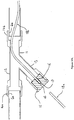
- a building 1 is situated in the vicinity of a public roadway 2.
- a water main (not shown) and a trunk cable 4.
- An individual property water supply pipe 6 branches off the water main to enter the building 1.
- the pipe 6 thus provides a supply of water for use within building 1.
- the flow of water within the pipe 6 is controlled by pavement stopcock 3 provided within a covered hole 3a and building stopcock 5 provided within building 1.
- a branch cable branches off trunk cable 4 and continues to enter building 1.
- the branch cable thus provides a connection between one or more nodes in building 1 and external nodes connected directly or indirectly to trunk cable 4.
- the trunk cable 4 may be laid along a dedicated conduit or a convenient length of sewer, water supply pipe or storm drain as appropriate.
- the trunk cable 4 is typically part of a network comprising one or more trunk cables 4 wherein the or each trunk cable 4 is laid along dedicated conduit and/or convenient lengths of sewer, water supply pipe or storm drain as required.
- Figure 5 illustrates schematically, how a trunk cable 4 may pass between a sewer branch 101 (for example) and a trench 104.
- the Trench 104 may enable the cable 4 to exit the sewer 101 and travel to the junction box 7.
- the cable 4 is shown fixed to the side of the sewer 101, however it need not be fixed there and may in alternative solutions be fixed or laid freely in another position within the sewer 101.
- the cable 4 exits the sewer branch 101 along an access shaft 109 and then along a duct 111 into trench 104.
- the access shaft 109 is provided with a cover 110 and is situated in roadway 2.
- suitable sealing means 113 may be provided.
- the sealing means 113 is adapted to form a substantially airtight seal between its exterior surface and the interior surface of duct 111, as is shown in figures 4a and 4b .
- the sealing means 113 is also provided with a central passageway through which trunk cable 4 may pass.
- the passageway is adapted to form a substantially airtight seal around the trunk cable 4.
- the sealing means 113 is formed from a resiliently deformable material, such that it can compensate for small irregularities on its exterior, on the interior of the duct 111, on the passageway or on the trunk cable 4, to maintain a seal.
- a suitable adhesive such as an epoxy resin
- the adhesive may be applied in the passageway around cable 105 to help retain the trunk cable 4 in place.
- the adhesive may also help maintain a substantially airtight seal where it is applied.
- the water supply pipe 6 is provided at the time of construction of the building 1 and is an underground pipe (as is the main).
- the cable may however be provided much later.
- it is conventional to provide a dedicated (and usually underground) conduit for cable. This can however be expensive and disruptive. This may be a particular problem if the cable has to cross a garden 1a that the owner of building 1 is loathe to see disturbed.
- the cable is laid along water supply pipe 6. This allows the cable to cross between the trunk cable 4 and the building 1 with minimal disturbance of the ground therebetween. This is achieved by introducing cable to pipe 6 by use of a suitable Y-junction 10 at location 10a and removing the cable from the pipe 6 by use of a second such Y-junction 10 at location 10b, It is of course alternatively possible to lay the cable in any other convenient length of pre-existing pipe such as a waste water pipe or a sewer.
- a microtrench 8 may be provided to carry the cable from junction box 7.
- the microtrench 8 may comprise a filled trench with the cable at its base.
- the filled trench may have a depth of say 150mm or so and a width of say 20-30mm or so.
- the Y-junction 10 comprises a leg 11 and two arms 12 and 13.
- Leg 11 and arm 12 are aligned along a common axis.
- Arm 13 projects from the Y-junction at a small angle to the common axis.
- the ends of leg 11 and are 12 are open and provided with compression fittings 14a, 14b. These allow the Y-junction to be fitted to open ends 6a, 6b facing a gap 6g in water supply pipe 6. When connected thus, a water flow path is provided between 6a and 6b along leg 11 and arm 12.
- the arm 13 is capped with an end cap 15.
- the end cap 15 additionally incorporates a cable passage 16 which allows a cable to pass therethrough.
- the cable is provided within a microduct tube 18.
- the microduct tube has separate sections (here labelled 18a and 18b) on either side of the end cap 15.
- a narrow neck 17 is provided with a small hole through which the cable rather than the microduct tube 18 can pass.
- the end cap 15 and the cable passage 16 may be formed of or lined with a resilient material such that it forms a seal with the walls of arm 13 and a seal around the microduct tubes 18a, 18b, thus preventing the escape of water.
- the diameter of the cable passage 16 may be matched to the expected diameter of the microduct tubes 18a, 18b.
- the end closure 25 is a simple bung having a cable passage 26 therethrough, which allows a cable within a microduct tube 18 to pass therethrough.
- the bung 25 and the cable passage 26 may be formed of or lined with a resilient material such that it forms a seal with the walls of arm 13 and a seal around the microduct tube 18 thus preventing the escape of water.
- the diameter of the cable passage 26 may be matched to the expected diameter of the microduct tube 18.
- the example bung 25 illustrated is provided with a threaded outer surface 25a adapted to interconnect with a thread 13a provided on projecting arm 13. It is of course possible that a bung 25 without such a thread may be substituted if desired.
- FIG 3c a more complex closure arrangement 35 is shown.
- an end cap 38 is retained in position by a sleeve 34.
- the sleeve 34 is provided with a thread 33b which engages with a thread 13b provided on the outside of the projecting arm 13.
- the end cap 38 has a passage 36 which allows a cable to pass therethrough.
- the cable is provided within a microduct tube 18.
- the microduct tube has separate sections (here labelled 18a and 18b) on either side of the end cap 38.
- a narrow neck 37 is provided with a small hole through which the cable rather than the microduct tube 18 can pass.
- the end cap 38 and the cable passage 16 may be formed of or lined with a resilient material such that it forms a seal with the walls of arm 13 and a seal around the microduct tubes 18a, 18b, thus preventing the escape of water.
- the diameter of the cable passage 36 may be matched to the expected diameter of the microduct tubes 18a, 18b.
- barbs or wedge projections 38a, 38b may be provided to engage the microduct tubes 18a, 18b and help maintain them in position.
- an O-ring 39 may be provided to improve the seal.
- FIG. 3d An embodiment of the invention is shown in figure 3d .
- the arm 13 is of considerably narrower diameter than arms 11, 12, such that it tightly encloses a cable passage 46 in the form of a duct adapted to fit around microduct 18.
- the microduct 18 enters and leaves the cable passage 46 via ends 45.
- the ends 45 are provided with barbed or wedged projections to improve the sealing and help retain the microduct 18 securely in position.
- the cable passage 16, 26, 36, 46 may be adapted to receive a bundle of microduct tubes 18 or a plurality of cable passages 16, 26, 36, 46 can be provided each operable to receive a single microduct tube 18 from a bundle of microduct tubes 18.
- the microduct tube 18 is typically of around say 4mm in diameter and is formed of an inert material such as HDPE (high density polyethylene) or similar. This prevents the water in pipe 6 being contaminated by the microduct tube 18 and prevents the water affecting the transmission of data along cable.
- the cable within the microduct tube 18 is typically an optical fibre and may be a multicore optical fibre. Such a cable having say 2-4 cores might have an external diameter in the range 2-3mm
- a cable provided with a suitable inert insulating coating may be directly inserted through a suitable cable passage 16 and the microduct tubes 18 omitted.
- the cable is typically an optical fibre and may be a multicore optical fibre.
- Such an insulated cable having say 2-4 cores might have an external diameter in the range 2-5mm.
- a method according to the present invention may be used.
- the method comprises the steps of turning off the water supply to pipe 6 using stopcocks 3 and 5.
- the next step is exposing a section of pipe 6 at location 10a and making a pair of cuts in pipe 6. Once the cuts are made, the section of pipe 6 lying between said cuts is removed leaving a gap 6g. This process is repeated adjacent to the building 1 at location 10b to leave a second gap 6g.
- the building 1 has a suitable form such as a cellar wherein the pipe 6 is exposed this location may be within the building 1.
- a cable is then laid along the section of pipe 6 between 10a and 10b, either directly or through a microduct tube 18b.
- Y-junctions 10 are inserted in the gaps 6g in pipe 6.
- the cable is threaded through the cable passages 16 provided in the end caps 15.
- the Y-junctions 10 are then sealed on to the ends of the pipe 6a, 6b facing the gaps using compression fixtures 14a, 14b. At this point the water supply to the pipe 6 can be switched back on.
- One end of the cable may then be connected to cable junction box 7 provided adjacent to or in the path of trunk cable 4.
- the other end of the cable may then be connected to suitable equipment within the building 1.
- the cable may be removed from the pipe 6 outside but adjacent to the building 1 and enter the building 1 through a suitable hole provided in an external wall.
Claims (19)
- Procédé de pose d'un câble de dérivation entre un câble (4) de jonction et un emplacement souhaité de noeud, comprenant les stades de
localisation d'un tuyau (6) préexistant d'adduction d'eau, de drain, d'eau usée ou d'égout pour l'emplacement du noeud voisin du câble (4) de jonction ; introduction du câble de dérivation dans le tuyau (6) préexistant ; passage du câble de dérivation dans le tuyau (6) préexistant et retrait du câble de dérivation du tuyau (6) préexistant au voisinage de l'emplacement du noeud ; l'introduction ou le retrait du câble du tuyau (6) préexistant étant rendu possible en prévoyant un moyen de transfert de câble, le moyen de transfert de câble comprenant une jonction (10) en Y, insérée dans un intervalle prévu dans le tuyau (6) préexistant, la jonction (10) en Y comprenant une jambe (11) et un bras (12) ayant des extrémités ouvertes propres à être reliées au tuyau (6) préexistant et un autre bras (13) ;
le câble étant fileté le long d'un tube (18) de micro canalisation et dans lequel l'autre bras (13) est d'un diamètre considérablement plus étroit que le bras (12) ouvert et que la branche (11), de manière à enfermer étroitement un passage (46) de câble, sous la forme d'une canalisation propre à s'adapter autour du tube (18) de micro canalisation, pour empêcher le passage d'eau le long du tube (18) de micro canalisation et dans lequel la micro canalisation (18) entre dans le passage (46) de câble et le quitte par des extrémités (45), les extrémités (45) étant pourvues de saillies à barbes ou à picots pour améliorer l'étanchéité et faciliter la retenue du tube (18) de micro canalisation fixement en position. - Procédé suivant la revendication 1, dans lequel le procédé comprend le stade de liaison du câble de dérivation au câble (4) de jonction, soit directement, soit par l'intermédiaire d'une boîte (7) de jonction appropriée et/ou le stade de liaison du câble de dérivation au noeud.
- Procédé suivant la revendication 2, dans lequel le câble de dérivation entre dans le tuyau (6) préexistant au voisinage de la boîte (7) de jonction, dans lequel le câble de dérivation se déplace dans un conduit approprié, tel qu'une microtranchée (8) ou un autre conduit classique entre la boîte (7) de jonction et le tuyau (6) préexistant.
- Procédé suivant la revendication 2 ou la revendication 3, dans lequel on relie câble de dérivation directement à un équipement approprié au noeud ou on le relie à une boîte (7) de jonction ou à un raccord permettant de relier un ou plusieurs dispositifs à un réseau.
- Procédé suivant l'une quelconque des revendications 2 à 4, dans lequel on retire le câble du tuyau (6) préexistant au voisinage d'un bâtiment dans lequel le noeud est prévu et on fait passer le câble dans un passage d'entrée propre à être relié au noeud au sein du bâtiment.
- Procédé suivant l'une quelconque des revendications 2 à 4, dans lequel on retire le câble du tuyau (6) préexistant au sein d'un bâtiment où le noeud est prévu.
- Procédé suivant la revendication 6, dans lequel le câble entre dans le tuyau (6) préexistant et/ou le quitte entre un robinet d'arrêt principal et un robinet d'arrêt de bâtiment dédié.
- Procédé suivant l'une quelconque des revendications précédentes, dans lequel on relie la branche (11) ouverte et le bras (12) de la jonction en Y au tuyau (6) préexistant par des raccords (14a, 14b) appropriés propres à sceller la jonction (10) Y au tuyau préexistant.
- Procédé suivant l'une quelconque des revendications précédentes, dans lequel le procédé incorpore le stade de formation d'un intervalle (6g) approprié dans le tuyau (6) préexistant.
- Procédé suivant la revendication 9, dans lequel on forme l'intervalle (6g) en utilisant un équipement de coupe.
- Procédé suivant l'une quelconque des revendications précédentes, dans lequel on pose le câble de jonction suivant un procédé comprenant les stades de : pose d'un câble dans un ou plusieurs tronçons d'un égout entre les deux points ; et là où il n'y a pas de tronçon convenable d'égout à un intervalle entre des longueurs convenables d'égout, on prévoit un tronçon de conduit de câble dédié entre lesdits tronçons d'égout et on pose le câble dans le conduit de câble dédié.
- Procédé suivant la revendication 11, dans lequel on pose le câble de jonction dans l'égout, en utilisant des techniques comprenant, mais sans limitation : pose du câble de manière lâche dans le canal d'écoulement de l'égout ; goupillage du câble aux parois de l'égout ou passage du câble dans une canalisation prévue dans l'égout.
- Procédé suivant la revendication 12, dans lequel, si le procédé implique la pose du câble de manière lâche dans le canal d'écoulement d'un égout, le procédé comprend les stades de montage d'un guide-câble approprié en des points où l'on souhaite ou il faut que le câble entre dans le canal d'écoulement ou le quitte et/ou le stade de montage de guides-câble de ce genre en des points où il faut que le câble entre ou quitte l'égout et sur chaque côté de points, tels que des jonctions ou des coudes de l'égout, où un câble dans le canal d'écoulement est susceptible de se mettre en travers du sens d'écoulement.
- Procédé suivant l'une quelconque des revendications 11 à 13, dans lequel on met le conduit de câble par une technique impliquant : creuser une tranchée, poser le câble dans la tranchée et remplir la tranchée.
- Procédé suivant l'une quelconque des revendications 11 à 14, dans lequel on prévoit des moyens (113) de scellement, en des points où le câble sort d'un égout, pour empêcher que des gaz nocifs s'échappent de l'égout, ou on les prévoit aux deux extrémités d'une canalisation portant le câble entre l'égout et le conduit dédié.
- Moyen de transfert de câble propre à introduire un câble ou à le retirer d'un tuyau (6) préexistant d'adduction d'eau, de drain, d'eau usée ou d'égout, comprenant une jonction (10) en Y, ayant une branche (11) ayant une extrémité ouverte propre à être reliée au tuyau (6) préexistant, un bras (12) ayant une extrémité ouverte propre à être reliée au tuyau (6) préexistant et un autre bras (13), le câble étant fileté le long d'un tube (18) de microcanalisation,
le moyen de transfert de câble comprenant, en outre, un passage (46) de câble, sous la forme d'une canalisation, dans lequel l'autre bras (13) est d'un diamètre considérablement plus petit que celui du bras (12) ouvert et de la branche (11),
caractérisé en ce que l'autre bras (13) enferme étroitement le passage (46) de câble, sous la forme d'une canalisation propre à s'adapter autour du tube (18) de micro canalisation, pour empêcher le passage de l'eau le long du tube (18) de microcanalisation, et dans lequel le tube (18) de microcanalisation entre dans le passage (46) de câble et le quitte par des extrémités (45), les extrémités (45) étant pourvues de saillies à barbes ou en picots, pour améliorer l'étanchéité et faciliter la retenue du tube (18) de microcanalisation fixé en position. - Moyen de transfert de câble suivant la revendication 7, dans lequel le bras (12) ouvert et la branche (11) de la jonction (10) en Y sont prévus suivant un axe linéaire commun.
- Moyen de transfert de câble suivant l'une quelconque des revendications 16 à 17, dans lequel le passage (46) de câble est conçu pour permettre le passage d'un faisceau de tubes (18) de microcanalisation.
- Moyen de transfert de câble suivant l'une quelconque des revendications 16 à 18, dans lequel la branche (11) ouverte et le bras (12) de la jonction (10) en Y sont reliés au tuyau (6) préexistant par l'intermédiaire de raccords (14a, 14b) propres à sceller la jonction (10) en Y au tuyau (6) préexistant.
Applications Claiming Priority (2)
| Application Number | Priority Date | Filing Date | Title |
|---|---|---|---|
| GBGB0816616.7A GB0816616D0 (en) | 2008-09-11 | 2008-09-11 | Laying network cables in water supply pipes |
| PCT/GB2009/051172 WO2010029365A2 (fr) | 2008-09-11 | 2009-09-11 | Pose de câbles de réseau dans des canalisations d’adduction d’eau |
Publications (2)
| Publication Number | Publication Date |
|---|---|
| EP2338213A2 EP2338213A2 (fr) | 2011-06-29 |
| EP2338213B1 true EP2338213B1 (fr) | 2019-08-21 |
Family
ID=39929986
Family Applications (1)
| Application Number | Title | Priority Date | Filing Date |
|---|---|---|---|
| EP09785627.2A Not-in-force EP2338213B1 (fr) | 2008-09-11 | 2009-09-11 | Pose de câbles de réseau dans des canalisations d adduction d eau |
Country Status (7)
| Country | Link |
|---|---|
| US (1) | US8695214B2 (fr) |
| EP (1) | EP2338213B1 (fr) |
| AU (1) | AU2009290647B2 (fr) |
| GB (2) | GB0816616D0 (fr) |
| NZ (1) | NZ592205A (fr) |
| WO (1) | WO2010029365A2 (fr) |
| ZA (1) | ZA201102664B (fr) |
Families Citing this family (7)
| Publication number | Priority date | Publication date | Assignee | Title |
|---|---|---|---|---|
| DE102010031978A1 (de) * | 2010-07-22 | 2012-01-26 | Ewe Netz Gmbh | Leitungssystem |
| CN103379163B (zh) * | 2012-04-25 | 2016-04-06 | 阿里巴巴集团控股有限公司 | 一种业务对象的确定方法以及确定装置 |
| GB2522230A (en) * | 2014-01-17 | 2015-07-22 | Deflux Holdings Ltd | Method and apparatus for removing a cable core from a cable sheath |
| GB2547405A (en) * | 2015-11-16 | 2017-08-23 | Craley Group Ltd | A pipe connector fitting |
| CN109737271A (zh) * | 2019-02-28 | 2019-05-10 | 西安石油大学 | 一种用于管道内防腐的柔性阳极安装结构 |
| IT202000021091A1 (it) * | 2020-09-07 | 2022-03-07 | Orazio Fiume | Metodo e sistema di alimentazione elettrica di un ventilconvettore |
| US11621502B2 (en) * | 2020-09-10 | 2023-04-04 | Baker Hughes Oilfield Operations Llc | Hybrid cable crimp |
Citations (1)
| Publication number | Priority date | Publication date | Assignee | Title |
|---|---|---|---|---|
| US20030068143A1 (en) * | 2001-10-10 | 2003-04-10 | Eric Martinez | Method and apparatus providing fiber optic cables through gas service pipes |
Family Cites Families (10)
| Publication number | Priority date | Publication date | Assignee | Title |
|---|---|---|---|---|
| DE3140928C2 (de) * | 1981-10-15 | 1989-12-14 | Otto Niedung KG, 3000 Hannover | Vorrichtung für das nachträgliche Einziehen von Fernmeldekabeln |
| GB2267005A (en) | 1992-05-15 | 1993-11-17 | Delta Technical Services Ltd | Data transmission |
| NL1001961C2 (nl) | 1995-12-21 | 1997-06-24 | Nederland Ptt | Werkwijze voor het installeren van een buizenstelsel met aftakkingen voor telecommunicatiekabels, alsmede een aftakelement voor toepassing bij die werkwijze. |
| DE19734274B4 (de) * | 1997-08-07 | 2010-04-08 | Norddeutsche Seekabelwerke Gmbh & Co. Kg | Kommunikationsnetz mit Lichtwellenleitern zwischen Teilnehmern und Kommunikationzentralen in bestehenden Versorgungsleitungen |
| US6019351A (en) * | 1998-01-15 | 2000-02-01 | Vikimatic Sales, Inc. | Method and apparatus for introducing a cable into a conduit |
| JP3574895B2 (ja) | 2000-01-26 | 2004-10-06 | 智美 中村 | 雨水管通信線 |
| WO2001092921A2 (fr) * | 2000-06-01 | 2001-12-06 | Bbnt Solutions Llc | Systeme et procede de deploiement de reseaux a fibres optiques par des systemes de distribution d'eau |
| US6584252B1 (en) * | 2000-12-14 | 2003-06-24 | Cisco Technology, Inc. | Method and system for providing fiber optic cable to end users |
| US20020114595A1 (en) * | 2001-02-16 | 2002-08-22 | Hanan Potash | Efficient method and system for the installation of data conduit in pre-existing structures |
| GB0614416D0 (en) * | 2006-07-20 | 2006-08-30 | Thomas Elfed | Laying network cables in sewers |
-
2008
- 2008-09-11 GB GBGB0816616.7A patent/GB0816616D0/en not_active Ceased
-
2009
- 2009-09-11 NZ NZ592205592205A patent/NZ592205A/xx not_active IP Right Cessation
- 2009-09-11 US US13/063,493 patent/US8695214B2/en active Active
- 2009-09-11 AU AU2009290647A patent/AU2009290647B2/en not_active Ceased
- 2009-09-11 GB GB0915955.9A patent/GB2463372B/en active Active
- 2009-09-11 EP EP09785627.2A patent/EP2338213B1/fr not_active Not-in-force
- 2009-09-11 WO PCT/GB2009/051172 patent/WO2010029365A2/fr active Application Filing
-
2011
- 2011-04-11 ZA ZA2011/02664A patent/ZA201102664B/en unknown
Patent Citations (1)
| Publication number | Priority date | Publication date | Assignee | Title |
|---|---|---|---|---|
| US20030068143A1 (en) * | 2001-10-10 | 2003-04-10 | Eric Martinez | Method and apparatus providing fiber optic cables through gas service pipes |
Also Published As
| Publication number | Publication date |
|---|---|
| WO2010029365A3 (fr) | 2010-05-06 |
| EP2338213A2 (fr) | 2011-06-29 |
| NZ592205A (en) | 2013-06-28 |
| WO2010029365A2 (fr) | 2010-03-18 |
| GB0915955D0 (en) | 2009-10-28 |
| ZA201102664B (en) | 2012-01-25 |
| US8695214B2 (en) | 2014-04-15 |
| US20120012386A1 (en) | 2012-01-19 |
| AU2009290647B2 (en) | 2015-05-21 |
| GB2463372B (en) | 2013-02-13 |
| GB0816616D0 (en) | 2008-10-22 |
| AU2009290647A1 (en) | 2010-03-18 |
| GB2463372A (en) | 2010-03-17 |
Similar Documents
| Publication | Publication Date | Title |
|---|---|---|
| EP2338213B1 (fr) | Pose de câbles de réseau dans des canalisations d adduction d eau | |
| CA2372678C (fr) | Procede pour poser des cables de donnees et dispositif de transmission de donnees pour une installation communale de conduites de gaz, de pression ou d'eaux usees, comportant au moins une conduite d'eaux usees et une gaine technique | |
| JP3833267B2 (ja) | 光ファイバケーブルネットワーク | |
| US20030068143A1 (en) | Method and apparatus providing fiber optic cables through gas service pipes | |
| US20010010781A1 (en) | Method of laying data cables and the like in underground pipes and pipe-cable combinations | |
| AU2007274866B2 (en) | Laying network cables in sewers | |
| EP2064789B1 (fr) | Pose de cables de reseau dans des egouts | |
| EP2594000B1 (fr) | Raccords de câble étanches | |
| US8864107B2 (en) | Laying network cables in sewers | |
| JPH03270613A (ja) | 流体輸送管を利用した通信線の地下配線方法 | |
| AU2006200987B2 (en) | Subsurface fibre optic cable network installation | |
| MX2012009653A (es) | Sistema de ducto para componentes de fibra optica. | |
| Anderson | CIPP Process: Installation of Fiber Optic Cables in Sewers | |
| JPH10290517A (ja) | 通信ケーブル用マンホール | |
| WO2015001332A1 (fr) | Système de transfert de câble amélioré | |
| EP2166394B1 (fr) | Protection pour chambre souterraine | |
| KR20020084866A (ko) | 관로구 지수 공법 | |
| MXPA00012824A (es) | Metodo para tender cables de datos y dispositivo de transmision de datos para un sistema municipal de tuberia de gas, presion o agua de desecho que comprende al menos un desague de agua de desecho y un registro de acceso | |
| JP2000347078A (ja) | 下水管路内敷設光ファイバーケーブル分岐部の構造 | |
| JPH08338061A (ja) | 既設埋設管渠を利用した情報通信ネットワークの構築方法 |
Legal Events
| Date | Code | Title | Description |
|---|---|---|---|
| PUAI | Public reference made under article 153(3) epc to a published international application that has entered the european phase |
Free format text: ORIGINAL CODE: 0009012 |
|
| 17P | Request for examination filed |
Effective date: 20110411 |
|
| AK | Designated contracting states |
Kind code of ref document: A2 Designated state(s): AT BE BG CH CY CZ DE DK EE ES FI FR GB GR HR HU IE IS IT LI LT LU LV MC MK MT NL NO PL PT RO SE SI SK SM TR |
|
| AX | Request for extension of the european patent |
Extension state: AL BA RS |
|
| DAX | Request for extension of the european patent (deleted) | ||
| RAP1 | Party data changed (applicant data changed or rights of an application transferred) |
Owner name: CMS (CABLE MANAGEMENT SUPPLIES) PLC |
|
| 17Q | First examination report despatched |
Effective date: 20140311 |
|
| RAP1 | Party data changed (applicant data changed or rights of an application transferred) |
Owner name: CRALEY GROUP LIMITED |
|
| STAA | Information on the status of an ep patent application or granted ep patent |
Free format text: STATUS: EXAMINATION IS IN PROGRESS |
|
| GRAP | Despatch of communication of intention to grant a patent |
Free format text: ORIGINAL CODE: EPIDOSNIGR1 |
|
| STAA | Information on the status of an ep patent application or granted ep patent |
Free format text: STATUS: GRANT OF PATENT IS INTENDED |
|
| RIC1 | Information provided on ipc code assigned before grant |
Ipc: G02B 6/44 20060101ALI20181207BHEP Ipc: H02G 9/06 20060101ALI20181207BHEP Ipc: G02B 6/50 20060101ALI20181207BHEP Ipc: H02G 1/08 20060101AFI20181207BHEP |
|
| INTG | Intention to grant announced |
Effective date: 20190109 |
|
| RBV | Designated contracting states (corrected) |
Designated state(s): AT BE BG CH CY CZ DE DK EE ES FI FR GR HR HU IE IS IT LI LT LU LV MC MK MT NL NO PL PT RO SE SI SK SM TR |
|
| GRAS | Grant fee paid |
Free format text: ORIGINAL CODE: EPIDOSNIGR3 |
|
| GRAA | (expected) grant |
Free format text: ORIGINAL CODE: 0009210 |
|
| STAA | Information on the status of an ep patent application or granted ep patent |
Free format text: STATUS: THE PATENT HAS BEEN GRANTED |
|
| AK | Designated contracting states |
Kind code of ref document: B1 Designated state(s): AT BE BG CH CY CZ DE DK EE ES FI FR GR HR HU IE IS IT LI LT LU LV MC MK MT NL NO PL PT RO SE SI SK SM TR |
|
| REG | Reference to a national code |
Ref country code: CH Ref legal event code: EP |
|
| REG | Reference to a national code |
Ref country code: DE Ref legal event code: R096 Ref document number: 602009059556 Country of ref document: DE |
|
| REG | Reference to a national code |
Ref country code: AT Ref legal event code: REF Ref document number: 1170828 Country of ref document: AT Kind code of ref document: T Effective date: 20190915 |
|
| REG | Reference to a national code |
Ref country code: IE Ref legal event code: FG4D |
|
| REG | Reference to a national code |
Ref country code: LT Ref legal event code: MG4D |
|
| REG | Reference to a national code |
Ref country code: NL Ref legal event code: MP Effective date: 20190821 |
|
| PG25 | Lapsed in a contracting state [announced via postgrant information from national office to epo] |
Ref country code: FI Free format text: LAPSE BECAUSE OF FAILURE TO SUBMIT A TRANSLATION OF THE DESCRIPTION OR TO PAY THE FEE WITHIN THE PRESCRIBED TIME-LIMIT Effective date: 20190821 Ref country code: PT Free format text: LAPSE BECAUSE OF FAILURE TO SUBMIT A TRANSLATION OF THE DESCRIPTION OR TO PAY THE FEE WITHIN THE PRESCRIBED TIME-LIMIT Effective date: 20191223 Ref country code: HR Free format text: LAPSE BECAUSE OF FAILURE TO SUBMIT A TRANSLATION OF THE DESCRIPTION OR TO PAY THE FEE WITHIN THE PRESCRIBED TIME-LIMIT Effective date: 20190821 Ref country code: SE Free format text: LAPSE BECAUSE OF FAILURE TO SUBMIT A TRANSLATION OF THE DESCRIPTION OR TO PAY THE FEE WITHIN THE PRESCRIBED TIME-LIMIT Effective date: 20190821 Ref country code: BG Free format text: LAPSE BECAUSE OF FAILURE TO SUBMIT A TRANSLATION OF THE DESCRIPTION OR TO PAY THE FEE WITHIN THE PRESCRIBED TIME-LIMIT Effective date: 20191121 Ref country code: NL Free format text: LAPSE BECAUSE OF FAILURE TO SUBMIT A TRANSLATION OF THE DESCRIPTION OR TO PAY THE FEE WITHIN THE PRESCRIBED TIME-LIMIT Effective date: 20190821 Ref country code: LT Free format text: LAPSE BECAUSE OF FAILURE TO SUBMIT A TRANSLATION OF THE DESCRIPTION OR TO PAY THE FEE WITHIN THE PRESCRIBED TIME-LIMIT Effective date: 20190821 Ref country code: NO Free format text: LAPSE BECAUSE OF FAILURE TO SUBMIT A TRANSLATION OF THE DESCRIPTION OR TO PAY THE FEE WITHIN THE PRESCRIBED TIME-LIMIT Effective date: 20191121 |
|
| PGFP | Annual fee paid to national office [announced via postgrant information from national office to epo] |
Ref country code: DE Payment date: 20191118 Year of fee payment: 11 |
|
| PG25 | Lapsed in a contracting state [announced via postgrant information from national office to epo] |
Ref country code: ES Free format text: LAPSE BECAUSE OF FAILURE TO SUBMIT A TRANSLATION OF THE DESCRIPTION OR TO PAY THE FEE WITHIN THE PRESCRIBED TIME-LIMIT Effective date: 20190821 Ref country code: LV Free format text: LAPSE BECAUSE OF FAILURE TO SUBMIT A TRANSLATION OF THE DESCRIPTION OR TO PAY THE FEE WITHIN THE PRESCRIBED TIME-LIMIT Effective date: 20190821 Ref country code: IS Free format text: LAPSE BECAUSE OF FAILURE TO SUBMIT A TRANSLATION OF THE DESCRIPTION OR TO PAY THE FEE WITHIN THE PRESCRIBED TIME-LIMIT Effective date: 20191221 Ref country code: GR Free format text: LAPSE BECAUSE OF FAILURE TO SUBMIT A TRANSLATION OF THE DESCRIPTION OR TO PAY THE FEE WITHIN THE PRESCRIBED TIME-LIMIT Effective date: 20191122 |
|
| PGFP | Annual fee paid to national office [announced via postgrant information from national office to epo] |
Ref country code: FR Payment date: 20191128 Year of fee payment: 11 |
|
| REG | Reference to a national code |
Ref country code: AT Ref legal event code: MK05 Ref document number: 1170828 Country of ref document: AT Kind code of ref document: T Effective date: 20190821 |
|
| PG25 | Lapsed in a contracting state [announced via postgrant information from national office to epo] |
Ref country code: TR Free format text: LAPSE BECAUSE OF FAILURE TO SUBMIT A TRANSLATION OF THE DESCRIPTION OR TO PAY THE FEE WITHIN THE PRESCRIBED TIME-LIMIT Effective date: 20190821 |
|
| PG25 | Lapsed in a contracting state [announced via postgrant information from national office to epo] |
Ref country code: IT Free format text: LAPSE BECAUSE OF FAILURE TO SUBMIT A TRANSLATION OF THE DESCRIPTION OR TO PAY THE FEE WITHIN THE PRESCRIBED TIME-LIMIT Effective date: 20190821 Ref country code: EE Free format text: LAPSE BECAUSE OF FAILURE TO SUBMIT A TRANSLATION OF THE DESCRIPTION OR TO PAY THE FEE WITHIN THE PRESCRIBED TIME-LIMIT Effective date: 20190821 Ref country code: PL Free format text: LAPSE BECAUSE OF FAILURE TO SUBMIT A TRANSLATION OF THE DESCRIPTION OR TO PAY THE FEE WITHIN THE PRESCRIBED TIME-LIMIT Effective date: 20190821 Ref country code: RO Free format text: LAPSE BECAUSE OF FAILURE TO SUBMIT A TRANSLATION OF THE DESCRIPTION OR TO PAY THE FEE WITHIN THE PRESCRIBED TIME-LIMIT Effective date: 20190821 Ref country code: AT Free format text: LAPSE BECAUSE OF FAILURE TO SUBMIT A TRANSLATION OF THE DESCRIPTION OR TO PAY THE FEE WITHIN THE PRESCRIBED TIME-LIMIT Effective date: 20190821 Ref country code: DK Free format text: LAPSE BECAUSE OF FAILURE TO SUBMIT A TRANSLATION OF THE DESCRIPTION OR TO PAY THE FEE WITHIN THE PRESCRIBED TIME-LIMIT Effective date: 20190821 |
|
| PG25 | Lapsed in a contracting state [announced via postgrant information from national office to epo] |
Ref country code: CZ Free format text: LAPSE BECAUSE OF FAILURE TO SUBMIT A TRANSLATION OF THE DESCRIPTION OR TO PAY THE FEE WITHIN THE PRESCRIBED TIME-LIMIT Effective date: 20190821 Ref country code: SK Free format text: LAPSE BECAUSE OF FAILURE TO SUBMIT A TRANSLATION OF THE DESCRIPTION OR TO PAY THE FEE WITHIN THE PRESCRIBED TIME-LIMIT Effective date: 20190821 Ref country code: SM Free format text: LAPSE BECAUSE OF FAILURE TO SUBMIT A TRANSLATION OF THE DESCRIPTION OR TO PAY THE FEE WITHIN THE PRESCRIBED TIME-LIMIT Effective date: 20190821 Ref country code: MC Free format text: LAPSE BECAUSE OF FAILURE TO SUBMIT A TRANSLATION OF THE DESCRIPTION OR TO PAY THE FEE WITHIN THE PRESCRIBED TIME-LIMIT Effective date: 20190821 Ref country code: IS Free format text: LAPSE BECAUSE OF FAILURE TO SUBMIT A TRANSLATION OF THE DESCRIPTION OR TO PAY THE FEE WITHIN THE PRESCRIBED TIME-LIMIT Effective date: 20200224 |
|
| REG | Reference to a national code |
Ref country code: CH Ref legal event code: PL |
|
| REG | Reference to a national code |
Ref country code: DE Ref legal event code: R097 Ref document number: 602009059556 Country of ref document: DE |
|
| PLBE | No opposition filed within time limit |
Free format text: ORIGINAL CODE: 0009261 |
|
| STAA | Information on the status of an ep patent application or granted ep patent |
Free format text: STATUS: NO OPPOSITION FILED WITHIN TIME LIMIT |
|
| PG2D | Information on lapse in contracting state deleted |
Ref country code: IS |
|
| PG25 | Lapsed in a contracting state [announced via postgrant information from national office to epo] |
Ref country code: LI Free format text: LAPSE BECAUSE OF NON-PAYMENT OF DUE FEES Effective date: 20190930 Ref country code: CH Free format text: LAPSE BECAUSE OF NON-PAYMENT OF DUE FEES Effective date: 20190930 Ref country code: IE Free format text: LAPSE BECAUSE OF NON-PAYMENT OF DUE FEES Effective date: 20190911 Ref country code: LU Free format text: LAPSE BECAUSE OF NON-PAYMENT OF DUE FEES Effective date: 20190911 |
|
| REG | Reference to a national code |
Ref country code: BE Ref legal event code: MM Effective date: 20190930 |
|
| 26N | No opposition filed |
Effective date: 20200603 |
|
| PG25 | Lapsed in a contracting state [announced via postgrant information from national office to epo] |
Ref country code: BE Free format text: LAPSE BECAUSE OF NON-PAYMENT OF DUE FEES Effective date: 20190930 Ref country code: SI Free format text: LAPSE BECAUSE OF FAILURE TO SUBMIT A TRANSLATION OF THE DESCRIPTION OR TO PAY THE FEE WITHIN THE PRESCRIBED TIME-LIMIT Effective date: 20190821 |
|
| REG | Reference to a national code |
Ref country code: DE Ref legal event code: R119 Ref document number: 602009059556 Country of ref document: DE |
|
| PG25 | Lapsed in a contracting state [announced via postgrant information from national office to epo] |
Ref country code: CY Free format text: LAPSE BECAUSE OF FAILURE TO SUBMIT A TRANSLATION OF THE DESCRIPTION OR TO PAY THE FEE WITHIN THE PRESCRIBED TIME-LIMIT Effective date: 20190821 |
|
| PG25 | Lapsed in a contracting state [announced via postgrant information from national office to epo] |
Ref country code: FR Free format text: LAPSE BECAUSE OF NON-PAYMENT OF DUE FEES Effective date: 20200930 Ref country code: HU Free format text: LAPSE BECAUSE OF FAILURE TO SUBMIT A TRANSLATION OF THE DESCRIPTION OR TO PAY THE FEE WITHIN THE PRESCRIBED TIME-LIMIT; INVALID AB INITIO Effective date: 20090911 Ref country code: MT Free format text: LAPSE BECAUSE OF FAILURE TO SUBMIT A TRANSLATION OF THE DESCRIPTION OR TO PAY THE FEE WITHIN THE PRESCRIBED TIME-LIMIT Effective date: 20190821 Ref country code: DE Free format text: LAPSE BECAUSE OF NON-PAYMENT OF DUE FEES Effective date: 20210401 |
|
| PG25 | Lapsed in a contracting state [announced via postgrant information from national office to epo] |
Ref country code: MK Free format text: LAPSE BECAUSE OF FAILURE TO SUBMIT A TRANSLATION OF THE DESCRIPTION OR TO PAY THE FEE WITHIN THE PRESCRIBED TIME-LIMIT Effective date: 20190821 |