EP2338213B1 - Laying network cables in water supply pipes - Google Patents
Laying network cables in water supply pipes Download PDFInfo
- Publication number
- EP2338213B1 EP2338213B1 EP09785627.2A EP09785627A EP2338213B1 EP 2338213 B1 EP2338213 B1 EP 2338213B1 EP 09785627 A EP09785627 A EP 09785627A EP 2338213 B1 EP2338213 B1 EP 2338213B1
- Authority
- EP
- European Patent Office
- Prior art keywords
- cable
- sewer
- existing pipe
- arm
- junction
- Prior art date
- Legal status (The legal status is an assumption and is not a legal conclusion. Google has not performed a legal analysis and makes no representation as to the accuracy of the status listed.)
- Not-in-force
Links
- XLYOFNOQVPJJNP-UHFFFAOYSA-N water Substances O XLYOFNOQVPJJNP-UHFFFAOYSA-N 0.000 title claims description 39
- 238000000034 method Methods 0.000 claims description 46
- 238000007789 sealing Methods 0.000 claims description 19
- 239000007789 gas Substances 0.000 claims description 7
- 230000001473 noxious effect Effects 0.000 claims description 3
- 239000010865 sewage Substances 0.000 claims description 3
- 239000002351 wastewater Substances 0.000 claims description 3
- 239000000835 fiber Substances 0.000 description 14
- 239000000853 adhesive Substances 0.000 description 7
- 230000001070 adhesive effect Effects 0.000 description 7
- 230000000052 comparative effect Effects 0.000 description 7
- 238000005188 flotation Methods 0.000 description 5
- 239000000463 material Substances 0.000 description 5
- 239000013307 optical fiber Substances 0.000 description 5
- 230000006835 compression Effects 0.000 description 4
- 238000007906 compression Methods 0.000 description 4
- 239000010410 layer Substances 0.000 description 4
- 239000011248 coating agent Substances 0.000 description 3
- 238000000576 coating method Methods 0.000 description 3
- 230000008878 coupling Effects 0.000 description 3
- 238000010168 coupling process Methods 0.000 description 3
- 238000005859 coupling reaction Methods 0.000 description 3
- 239000003822 epoxy resin Substances 0.000 description 3
- 239000002184 metal Substances 0.000 description 3
- 230000003287 optical effect Effects 0.000 description 3
- 229920000647 polyepoxide Polymers 0.000 description 3
- 239000012858 resilient material Substances 0.000 description 3
- 230000000717 retained effect Effects 0.000 description 3
- 239000004576 sand Substances 0.000 description 3
- 239000010426 asphalt Substances 0.000 description 2
- 229920001903 high density polyethylene Polymers 0.000 description 2
- 239000004700 high-density polyethylene Substances 0.000 description 2
- 230000006978 adaptation Effects 0.000 description 1
- 238000009412 basement excavation Methods 0.000 description 1
- 230000005540 biological transmission Effects 0.000 description 1
- 230000015572 biosynthetic process Effects 0.000 description 1
- 239000000919 ceramic Substances 0.000 description 1
- 239000003086 colorant Substances 0.000 description 1
- 238000004891 communication Methods 0.000 description 1
- 238000010276 construction Methods 0.000 description 1
- 239000012792 core layer Substances 0.000 description 1
- 230000000694 effects Effects 0.000 description 1
- 239000012530 fluid Substances 0.000 description 1
- 230000001939 inductive effect Effects 0.000 description 1
- 230000004048 modification Effects 0.000 description 1
- 238000012986 modification Methods 0.000 description 1
- 210000002445 nipple Anatomy 0.000 description 1
- 239000004033 plastic Substances 0.000 description 1
- 229920003023 plastic Polymers 0.000 description 1
- 238000009428 plumbing Methods 0.000 description 1
- 230000000135 prohibitive effect Effects 0.000 description 1
- 239000000126 substance Substances 0.000 description 1
- 230000007704 transition Effects 0.000 description 1
Images


Classifications
-
- G—PHYSICS
- G02—OPTICS
- G02B—OPTICAL ELEMENTS, SYSTEMS OR APPARATUS
- G02B6/00—Light guides; Structural details of arrangements comprising light guides and other optical elements, e.g. couplings
- G02B6/46—Processes or apparatus adapted for installing or repairing optical fibres or optical cables
- G02B6/47—Installation in buildings
- G02B6/475—Mechanical aspects of installing cables in ducts or the like for buildings
-
- H—ELECTRICITY
- H02—GENERATION; CONVERSION OR DISTRIBUTION OF ELECTRIC POWER
- H02G—INSTALLATION OF ELECTRIC CABLES OR LINES, OR OF COMBINED OPTICAL AND ELECTRIC CABLES OR LINES
- H02G1/00—Methods or apparatus specially adapted for installing, maintaining, repairing or dismantling electric cables or lines
- H02G1/06—Methods or apparatus specially adapted for installing, maintaining, repairing or dismantling electric cables or lines for laying cables, e.g. laying apparatus on vehicle
- H02G1/08—Methods or apparatus specially adapted for installing, maintaining, repairing or dismantling electric cables or lines for laying cables, e.g. laying apparatus on vehicle through tubing or conduit, e.g. rod or draw wire for pushing or pulling
- H02G1/086—Methods or apparatus specially adapted for installing, maintaining, repairing or dismantling electric cables or lines for laying cables, e.g. laying apparatus on vehicle through tubing or conduit, e.g. rod or draw wire for pushing or pulling using fluid as pulling means, e.g. liquid, pressurised gas or suction means
-
- G—PHYSICS
- G02—OPTICS
- G02B—OPTICAL ELEMENTS, SYSTEMS OR APPARATUS
- G02B6/00—Light guides; Structural details of arrangements comprising light guides and other optical elements, e.g. couplings
- G02B6/46—Processes or apparatus adapted for installing or repairing optical fibres or optical cables
- G02B6/50—Underground or underwater installation; Installation through tubing, conduits or ducts
-
- H—ELECTRICITY
- H02—GENERATION; CONVERSION OR DISTRIBUTION OF ELECTRIC POWER
- H02G—INSTALLATION OF ELECTRIC CABLES OR LINES, OR OF COMBINED OPTICAL AND ELECTRIC CABLES OR LINES
- H02G1/00—Methods or apparatus specially adapted for installing, maintaining, repairing or dismantling electric cables or lines
- H02G1/06—Methods or apparatus specially adapted for installing, maintaining, repairing or dismantling electric cables or lines for laying cables, e.g. laying apparatus on vehicle
- H02G1/08—Methods or apparatus specially adapted for installing, maintaining, repairing or dismantling electric cables or lines for laying cables, e.g. laying apparatus on vehicle through tubing or conduit, e.g. rod or draw wire for pushing or pulling
-
- H—ELECTRICITY
- H02—GENERATION; CONVERSION OR DISTRIBUTION OF ELECTRIC POWER
- H02G—INSTALLATION OF ELECTRIC CABLES OR LINES, OR OF COMBINED OPTICAL AND ELECTRIC CABLES OR LINES
- H02G9/00—Installations of electric cables or lines in or on the ground or water
- H02G9/06—Installations of electric cables or lines in or on the ground or water in underground tubes or conduits; Tubes or conduits therefor
-
- Y—GENERAL TAGGING OF NEW TECHNOLOGICAL DEVELOPMENTS; GENERAL TAGGING OF CROSS-SECTIONAL TECHNOLOGIES SPANNING OVER SEVERAL SECTIONS OF THE IPC; TECHNICAL SUBJECTS COVERED BY FORMER USPC CROSS-REFERENCE ART COLLECTIONS [XRACs] AND DIGESTS
- Y10—TECHNICAL SUBJECTS COVERED BY FORMER USPC
- Y10T—TECHNICAL SUBJECTS COVERED BY FORMER US CLASSIFICATION
- Y10T29/00—Metal working
- Y10T29/49—Method of mechanical manufacture
- Y10T29/49002—Electrical device making
- Y10T29/49117—Conductor or circuit manufacturing
- Y10T29/49169—Assembling electrical component directly to terminal or elongated conductor
-
- Y—GENERAL TAGGING OF NEW TECHNOLOGICAL DEVELOPMENTS; GENERAL TAGGING OF CROSS-SECTIONAL TECHNOLOGIES SPANNING OVER SEVERAL SECTIONS OF THE IPC; TECHNICAL SUBJECTS COVERED BY FORMER USPC CROSS-REFERENCE ART COLLECTIONS [XRACs] AND DIGESTS
- Y10—TECHNICAL SUBJECTS COVERED BY FORMER USPC
- Y10T—TECHNICAL SUBJECTS COVERED BY FORMER US CLASSIFICATION
- Y10T29/00—Metal working
- Y10T29/53—Means to assemble or disassemble
- Y10T29/5367—Coupling to conduit
Definitions
- the present invention relates to the laying of cables in water supply pipes.
- a dedicated conduit may be required. In some locations this distance may be relatively short, for instance in city centres and thus fitting a dedicated conduit is relatively low in cost and low in disruption. In other locations this distance may be longer or may cross private property. In such locations, the cost of providing a conduit and/or the disruption caused by digging up the private property to lay the conduit may be prohibitive. For instance in many suburban locations connection to a cable television network requires a cable conduit to be laid across a homeowner's front garden from a trunk cable running along or alongside the public roadway. This can require the digging of a trench through the garden which may be sufficiently expensive and/or unsightly to dissuade the homeowner from ordering a connection to the network.
- DE19734274 (A1 ) discloses a network having optical waveguides between subscribers and communication centres in existing supply lines for fluid media e.g water, sewage gas or heat.
- the waveguides are fed into the supply lines via conduits.
- the waveguides have a coating to protect against the effect of the medium used in the supply lines.
- Individual waveguides may be inserted into the supply lines and several individual waveguides may be combined into a connecting waveguide.
- the conduit unit may have a removable stopper with openings for the waveguides. The openings have gas and water tight seals.
- US6584252 (B1 ) discloses a method for providing fibre optic cable to an end user including disposing the fibre optic cable having first and second ends within a sewer line coupled to a premises of the end user, and coupling the first end of the fibre optic cable to a network interface device inside the premises.
- the method may further include disposing an optical splitter within a main sewer line coupled to the sewer line and coupling the second end of the fibre optic cable to the optical splitter.
- WO0192921 A1 discloses deploying a fiber optic network through a water distribution system by creating an access point in a water pipe and positioning a cable spool in close proximity to the entry point before a capture device is then inserted into the exit point in the water pipeline, a flotation device is attached to the front end of the cable to be deployed and the flotation device is inserted into the water pipeline through the entry point.
- this document relies on the water current in the water pipeline to unspool the cable and carry the flotation device and fiber cable toward the exit point, at which the capture device captures the flotation device or the cable itself. The flotation device, along with the attached fiber cable, is then pulled through the exit point of the water pipeline.
- US2002114595 (A1 ) describes a method of laying fibre optic cables that involves modifying two segments of a pipe to provide entry and exit points for a data conduit. Modification of the pipe entails bisecting the pipe and inserting a wye-fitting between the resulting two sections.
- the wye-fitting may be the type commonly used in plumbing to attach a branch pipe to a main pipe. After the addition of the wye-fitting, the data conduit is introduced into the pipe, through a coupling inserted into the third leg of the wye-fitting.
- DE 31 40 928 A1 discloses a method for pulling telecommunications cables into supply lines, in which the free end of the cable is inserted into the tube through a connecting piece, is drawn through the tube as far as the outlet point by means of a driving body, using the flow pressure of the water, and is passed out through a further connecting piece.
- a tubular piece of the supply line is removed and replaced with a piece provided with a connecting piece which encloses an oblique angle of approximately 120 DEG to 160 DEG with the tube axis in the direction in which the cable is inserted and pulled through, and in that the special tubular piece is connected on both sides to the ends of the supply line.
- US 2003 068143A1 discloses a method and apparatus for providing fiber optic cables through gas service pipes wherein a flexible tube is disposed inside a gas
- a fiber optic cable is disposed through the inside of the tube, with each end of the cable outside the service pipe.
- a first nipple is joined to the service pipe at a first location convenient for connecting fiber optic cable to the building and provides a pass way between the inside and the outside of the pipe.
- a branch cable can pass from a trunk cable to a node location without providing a dedicated conduit.
- the method may further comprise the steps of connecting the branch cable to the trunk cable and/or connecting the branch cable to the node.
- the branch cable may be connected directly to the trunk cable or may be connected via suitable junction box.
- the branch cable may enter the water supply pipe adjacent to the junction box.
- the branch cable may travel along a suitable conduit such as a microtrench or other conventional conduit between the junction box and the pre-existing pipe.
- the branch cable may be connected directly to suitable equipment at the node or may be connected to a junction box or socket allowing one or more devices to be connected to the network.
- the cable may be removed from the pre-existing pipe adjacent to a building within which the node is provided. In such embodiments, the cable may then be passed through a suitable entry passageway to be connected to the node within the building. Additionally or alternatively, the cable may be removed from the pre-existing pipe within a building within which the node is provided. The cable may enter and leave the pre-existing pipe between a mains side stopcock and a dedicated building stopcock.
- the method includes the steps of providing a cable transfer means enabling a cable to be introduced to or removed from said pre-existing pipe.
- the cable transfer means comprise a Y-junction inserted into a gap provided in the pre-existing pipe.
- the leg and one arm of the Y-junction are open and have an open end adapted to be connected to the pre-existing pipe thereby providing a water flow path through the Y-junction.
- the open arm and the leg of the Y-junction may be provided in along a common linear axis.
- the other arm has a cable passage provided therethrough, wherein the cable is threaded along a microduct tube, wherein the other arm is of considerably narrower diameter than the open arm and the leg such that it tightly encloses the cable passage in the form of a duct adapted to fit around the microduct tube.
- the diameter of the passage may be matched to the expected microduct tube diameter. In such cases the diameter of the passage may be selected to be equal to or less than the expected diameter of the microduct tube, such that when deformed a watertight seal is maintained.
- the cable passage may be adapted to allow the passage of a bundle of microduct tubes.
- the open leg and arm of the Y-junction may be connected to the pre-existing pipe via suitable fittings.
- the fitting is preferably adapted to seal the Y-junction to the pre-existing pipe.
- the fitting may be a push fitting or a compression fitting and in particular may be a BSP or metric compression fitting.
- the method may incorporate the steps of forming a suitable gap in the pre-existing pipe.
- the gap may be formed by use of suitable cutting equipment.
- the method may incorporate the step of prior to forming the gap, turning off the water supply to the pre-existing pipe. This can make fitting the Y-junction simpler and minimise the water leakage and disruption caused by fitting the Y-junction.
- the Y-junction may be formed from any suitable material. Typically it may be formed from a suitable metal, plastic or ceramic substance.
- the cable may be any suitable form of cable.
- the cable is preferably provided with a suitable insulating coating.
- the cable may be an optical fibre.
- the fibre may have a single core or multiple cores. In one preferred embodiment the fibre may have 2-4 cores.
- the trunk cable may be laid in a dedicated conduit or may be laid along a sewer.
- the trunk cable may be laid according to the disclosure of our copending application WO2008/009969 .
- a method of laying a cable between two points comprising the steps of: laying a cable through one or more lengths of sewer between the two points; and where there is no convenient length of sewer or a gap between convenient lengths of sewer, providing a length of dedicated cable conduit between said lengths of sewer and laying said cable through said dedicated cable conduit.
- cables may be laid along water supply pipes, roadside drains, storm drains or similar.
- the cable may be laid through the sewer using any suitable technique.
- the techniques may include, but are not limited to: laying the cable loose in the flow channel of the sewer; pinning the cable to the walls of the sewer; or passing the cable through a duct provided in the sewer.
- the method may include the step of installing a suitable cable guide at points wherein the cable is desired or required to enter or leave the flow channel.
- the cable guide is preferably adapted to enable the cable to enter/exit the flow channel without significantly impeding the flow.
- the cable guide may comprise a body section and an arm section, the body section adapted to lie substantially flush with the wall of the flow channel and the arm section providing a passage for the cable between the flow channel and a point outside the flow channel.
- Such cable guides may be installed at points wherein the cable is required to enter or leave the sewer and on either side of points such as junctions or bends in the sewer wherein a cable in the flow channel is likely to lie across the direction of flow. In such areas, the cable may be laid outside the flow channel using any suitable other technique such as pinning the cable to the walls of the sewer; or passing the cable through a duct provided in the sewer.
- the method may involve the additional step of installing a suitable duct.
- the duct may be pre-installed in the sewer at the time of constructing the sewer.
- the duct may be pinned or otherwise affixed to the walls or ceiling of the sewer.
- the duct may be substantially continuous between the cable entry point and the cable exit point or may be comprised of a plurality of separate sections having gaps therebetween.
- the cable conduit may be provided by any suitable technique. Typically, this might involve digging a trench, laying the cable in the trench and filling the trench.
- the cable may be laid in ducting provided at the bottom of the trench.
- the trench may be filled in layers.
- the trench may be filled with a sand layer directly over the cable and a layer of hard core over the sand.
- a layer of concrete, tarmac, asphalt, bitumen or other suitable sealing/paving surface may be provided over the hardcore if required or desired.
- the method may further include laying a warning tape between the sand and the hard core layers. The warning tape is adapted to be detectable by the provision of a metal strip inlay and/or being printed with a visible warning.
- the provision of a metal strip allows the tape to be detected by the a scan of the area using an inductive detector. This may be routinely carried out prior to road excavation.
- the visible warning may comprise bright colours and/or distinctive patterns and/or a written warning message such as "Warning Fibre Cable ", or similar.
- the cable may exit the sewer by any suitable means.
- the cable will exit the sewer via a duct into the space below an access hatch or 'manhole'.
- sealing means may be provided at points wherein the cable exits a sewer, to prevent the escape of noxious gases from the sewer.
- sealing means may be provided at both ends of a duct carrying the cable between the sewer and the dedicated conduit.
- the sealing means may be of the type comprising: a body having an exterior adapted to fit the aperture through which the cable exits the sewer; and a passage through the body allowing the passage of said cable wherein the body is formed from a resiliently deformable material such that it forms a substantially air tight seal around the cable and a substantially airtight seal between the exterior of the body and the aperture.
- One or both ends of the sealing means may be adapted to make it easier to insert a cable. This may be achieved by adapting one or both ends to provide a recessed stepped end portion, a projecting stepped end portion or any other suitable adaptation.
- the sealing means may be adapted to fit a duct leading the cable away from the sewer.
- the sealing means may be retained in the duct with the aid of a suitable adhesive, such as an epoxy resin or similar.
- the cable may be retained in the sealing means with the aid of a suitable adhesive, such as an epoxy resin or similar.
- the adhesive is adapted to cure rapidly, even in the presence of water.
- the adhesive may also aid the formation of a substantially airtight seal.
- a building 1 is situated in the vicinity of a public roadway 2.
- a water main (not shown) and a trunk cable 4.
- An individual property water supply pipe 6 branches off the water main to enter the building 1.
- the pipe 6 thus provides a supply of water for use within building 1.
- the flow of water within the pipe 6 is controlled by pavement stopcock 3 provided within a covered hole 3a and building stopcock 5 provided within building 1.
- a branch cable branches off trunk cable 4 and continues to enter building 1.
- the branch cable thus provides a connection between one or more nodes in building 1 and external nodes connected directly or indirectly to trunk cable 4.
- the trunk cable 4 may be laid along a dedicated conduit or a convenient length of sewer, water supply pipe or storm drain as appropriate.
- the trunk cable 4 is typically part of a network comprising one or more trunk cables 4 wherein the or each trunk cable 4 is laid along dedicated conduit and/or convenient lengths of sewer, water supply pipe or storm drain as required.
- Figure 5 illustrates schematically, how a trunk cable 4 may pass between a sewer branch 101 (for example) and a trench 104.
- the Trench 104 may enable the cable 4 to exit the sewer 101 and travel to the junction box 7.
- the cable 4 is shown fixed to the side of the sewer 101, however it need not be fixed there and may in alternative solutions be fixed or laid freely in another position within the sewer 101.
- the cable 4 exits the sewer branch 101 along an access shaft 109 and then along a duct 111 into trench 104.
- the access shaft 109 is provided with a cover 110 and is situated in roadway 2.
- suitable sealing means 113 may be provided.
- the sealing means 113 is adapted to form a substantially airtight seal between its exterior surface and the interior surface of duct 111, as is shown in figures 4a and 4b .
- the sealing means 113 is also provided with a central passageway through which trunk cable 4 may pass.
- the passageway is adapted to form a substantially airtight seal around the trunk cable 4.
- the sealing means 113 is formed from a resiliently deformable material, such that it can compensate for small irregularities on its exterior, on the interior of the duct 111, on the passageway or on the trunk cable 4, to maintain a seal.
- a suitable adhesive such as an epoxy resin
- the adhesive may be applied in the passageway around cable 105 to help retain the trunk cable 4 in place.
- the adhesive may also help maintain a substantially airtight seal where it is applied.
- the water supply pipe 6 is provided at the time of construction of the building 1 and is an underground pipe (as is the main).
- the cable may however be provided much later.
- it is conventional to provide a dedicated (and usually underground) conduit for cable. This can however be expensive and disruptive. This may be a particular problem if the cable has to cross a garden 1a that the owner of building 1 is loathe to see disturbed.
- the cable is laid along water supply pipe 6. This allows the cable to cross between the trunk cable 4 and the building 1 with minimal disturbance of the ground therebetween. This is achieved by introducing cable to pipe 6 by use of a suitable Y-junction 10 at location 10a and removing the cable from the pipe 6 by use of a second such Y-junction 10 at location 10b, It is of course alternatively possible to lay the cable in any other convenient length of pre-existing pipe such as a waste water pipe or a sewer.
- a microtrench 8 may be provided to carry the cable from junction box 7.
- the microtrench 8 may comprise a filled trench with the cable at its base.
- the filled trench may have a depth of say 150mm or so and a width of say 20-30mm or so.
- the Y-junction 10 comprises a leg 11 and two arms 12 and 13.
- Leg 11 and arm 12 are aligned along a common axis.
- Arm 13 projects from the Y-junction at a small angle to the common axis.
- the ends of leg 11 and are 12 are open and provided with compression fittings 14a, 14b. These allow the Y-junction to be fitted to open ends 6a, 6b facing a gap 6g in water supply pipe 6. When connected thus, a water flow path is provided between 6a and 6b along leg 11 and arm 12.
- the arm 13 is capped with an end cap 15.
- the end cap 15 additionally incorporates a cable passage 16 which allows a cable to pass therethrough.
- the cable is provided within a microduct tube 18.
- the microduct tube has separate sections (here labelled 18a and 18b) on either side of the end cap 15.
- a narrow neck 17 is provided with a small hole through which the cable rather than the microduct tube 18 can pass.
- the end cap 15 and the cable passage 16 may be formed of or lined with a resilient material such that it forms a seal with the walls of arm 13 and a seal around the microduct tubes 18a, 18b, thus preventing the escape of water.
- the diameter of the cable passage 16 may be matched to the expected diameter of the microduct tubes 18a, 18b.
- the end closure 25 is a simple bung having a cable passage 26 therethrough, which allows a cable within a microduct tube 18 to pass therethrough.
- the bung 25 and the cable passage 26 may be formed of or lined with a resilient material such that it forms a seal with the walls of arm 13 and a seal around the microduct tube 18 thus preventing the escape of water.
- the diameter of the cable passage 26 may be matched to the expected diameter of the microduct tube 18.
- the example bung 25 illustrated is provided with a threaded outer surface 25a adapted to interconnect with a thread 13a provided on projecting arm 13. It is of course possible that a bung 25 without such a thread may be substituted if desired.
- FIG 3c a more complex closure arrangement 35 is shown.
- an end cap 38 is retained in position by a sleeve 34.
- the sleeve 34 is provided with a thread 33b which engages with a thread 13b provided on the outside of the projecting arm 13.
- the end cap 38 has a passage 36 which allows a cable to pass therethrough.
- the cable is provided within a microduct tube 18.
- the microduct tube has separate sections (here labelled 18a and 18b) on either side of the end cap 38.
- a narrow neck 37 is provided with a small hole through which the cable rather than the microduct tube 18 can pass.
- the end cap 38 and the cable passage 16 may be formed of or lined with a resilient material such that it forms a seal with the walls of arm 13 and a seal around the microduct tubes 18a, 18b, thus preventing the escape of water.
- the diameter of the cable passage 36 may be matched to the expected diameter of the microduct tubes 18a, 18b.
- barbs or wedge projections 38a, 38b may be provided to engage the microduct tubes 18a, 18b and help maintain them in position.
- an O-ring 39 may be provided to improve the seal.
- FIG. 3d An embodiment of the invention is shown in figure 3d .
- the arm 13 is of considerably narrower diameter than arms 11, 12, such that it tightly encloses a cable passage 46 in the form of a duct adapted to fit around microduct 18.
- the microduct 18 enters and leaves the cable passage 46 via ends 45.
- the ends 45 are provided with barbed or wedged projections to improve the sealing and help retain the microduct 18 securely in position.
- the cable passage 16, 26, 36, 46 may be adapted to receive a bundle of microduct tubes 18 or a plurality of cable passages 16, 26, 36, 46 can be provided each operable to receive a single microduct tube 18 from a bundle of microduct tubes 18.
- the microduct tube 18 is typically of around say 4mm in diameter and is formed of an inert material such as HDPE (high density polyethylene) or similar. This prevents the water in pipe 6 being contaminated by the microduct tube 18 and prevents the water affecting the transmission of data along cable.
- the cable within the microduct tube 18 is typically an optical fibre and may be a multicore optical fibre. Such a cable having say 2-4 cores might have an external diameter in the range 2-3mm
- a cable provided with a suitable inert insulating coating may be directly inserted through a suitable cable passage 16 and the microduct tubes 18 omitted.
- the cable is typically an optical fibre and may be a multicore optical fibre.
- Such an insulated cable having say 2-4 cores might have an external diameter in the range 2-5mm.
- a method according to the present invention may be used.
- the method comprises the steps of turning off the water supply to pipe 6 using stopcocks 3 and 5.
- the next step is exposing a section of pipe 6 at location 10a and making a pair of cuts in pipe 6. Once the cuts are made, the section of pipe 6 lying between said cuts is removed leaving a gap 6g. This process is repeated adjacent to the building 1 at location 10b to leave a second gap 6g.
- the building 1 has a suitable form such as a cellar wherein the pipe 6 is exposed this location may be within the building 1.
- a cable is then laid along the section of pipe 6 between 10a and 10b, either directly or through a microduct tube 18b.
- Y-junctions 10 are inserted in the gaps 6g in pipe 6.
- the cable is threaded through the cable passages 16 provided in the end caps 15.
- the Y-junctions 10 are then sealed on to the ends of the pipe 6a, 6b facing the gaps using compression fixtures 14a, 14b. At this point the water supply to the pipe 6 can be switched back on.
- One end of the cable may then be connected to cable junction box 7 provided adjacent to or in the path of trunk cable 4.
- the other end of the cable may then be connected to suitable equipment within the building 1.
- the cable may be removed from the pipe 6 outside but adjacent to the building 1 and enter the building 1 through a suitable hole provided in an external wall.
Description
- The present invention relates to the laying of cables in water supply pipes.
- In order to install a new node to a hardwired network or indeed to provide a new hardwired network, it is necessary to provide a cable linking the node to the various other nodes in the network. Often, such as in the case of cable television networks, this will require providing a branch cable connecting the new node to an existing trunk cable via which connection to the other nodes may be effected. The trunk cables will typically be laid in a pattern between one or more potential nodes, for instance the trunk cables may follow the local street pattern. The branch cables may then need to travel some distance from the trunk cable to reach the building in which the node is to be located.
- In order to allow the cable to traverse such distances a dedicated conduit may be required. In some locations this distance may be relatively short, for instance in city centres and thus fitting a dedicated conduit is relatively low in cost and low in disruption. In other locations this distance may be longer or may cross private property. In such locations, the cost of providing a conduit and/or the disruption caused by digging up the private property to lay the conduit may be prohibitive. For instance in many suburban locations connection to a cable television network requires a cable conduit to be laid across a homeowner's front garden from a trunk cable running along or alongside the public roadway. This can require the digging of a trench through the garden which may be sufficiently expensive and/or unsightly to dissuade the homeowner from ordering a connection to the network.
-
DE19734274 (A1 ) discloses a network having optical waveguides between subscribers and communication centres in existing supply lines for fluid media e.g water, sewage gas or heat. The waveguides are fed into the supply lines via conduits. The waveguides have a coating to protect against the effect of the medium used in the supply lines. Individual waveguides may be inserted into the supply lines and several individual waveguides may be combined into a connecting waveguide. The conduit unit may have a removable stopper with openings for the waveguides. The openings have gas and water tight seals. -
US6584252 (B1 ) discloses a method for providing fibre optic cable to an end user including disposing the fibre optic cable having first and second ends within a sewer line coupled to a premises of the end user, and coupling the first end of the fibre optic cable to a network interface device inside the premises. The method may further include disposing an optical splitter within a main sewer line coupled to the sewer line and coupling the second end of the fibre optic cable to the optical splitter. -
WO0192921 A1 -
US2002114595 (A1 ) describes a method of laying fibre optic cables that involves modifying two segments of a pipe to provide entry and exit points for a data conduit. Modification of the pipe entails bisecting the pipe and inserting a wye-fitting between the resulting two sections. The wye-fitting may be the type commonly used in plumbing to attach a branch pipe to a main pipe. After the addition of the wye-fitting, the data conduit is introduced into the pipe, through a coupling inserted into the third leg of the wye-fitting. -
DE 31 40 928 A1 discloses a method for pulling telecommunications cables into supply lines, in which the free end of the cable is inserted into the tube through a connecting piece, is drawn through the tube as far as the outlet point by means of a driving body, using the flow pressure of the water, and is passed out through a further connecting piece. In the inlet and outlet region of the telecommunications cable, a tubular piece of the supply line is removed and replaced with a piece provided with a connecting piece which encloses an oblique angle of approximately 120 DEG to 160 DEG with the tube axis in the direction in which the cable is inserted and pulled through, and in that the special tubular piece is connected on both sides to the ends of the supply line. -
US 2003 068143A1 discloses a method and apparatus for providing fiber optic cables through gas service pipes wherein a flexible tube is disposed inside a gas - service pipe and sealed at each end to an outside surface of the service pipe at a pressure fitting for providing access to the inside of the tube. A fiber optic cable is disposed through the inside of the tube, with each end of the cable outside the service pipe. A first nipple is joined to the service pipe at a first location convenient for connecting fiber optic cable to the building and provides a pass way between the inside and the outside of the pipe.
- It is therefore an object of the present invention to provide a new method of laying a branch cable between a trunk cable and a node location that alleviates or overcomes the above problems.
- According to a first aspect of the present invention there is provided a method of laying a branch cable according to
claim 1 of the appended claims. In this manner, a branch cable can pass from a trunk cable to a node location without providing a dedicated conduit. - The method may further comprise the steps of connecting the branch cable to the trunk cable and/or connecting the branch cable to the node. The branch cable may be connected directly to the trunk cable or may be connected via suitable junction box. The branch cable may enter the water supply pipe adjacent to the junction box. The branch cable may travel along a suitable conduit such as a microtrench or other conventional conduit between the junction box and the pre-existing pipe. The branch cable may be connected directly to suitable equipment at the node or may be connected to a junction box or socket allowing one or more devices to be connected to the network.
- The cable may be removed from the pre-existing pipe adjacent to a building within which the node is provided. In such embodiments, the cable may then be passed through a suitable entry passageway to be connected to the node within the building. Additionally or alternatively, the cable may be removed from the pre-existing pipe within a building within which the node is provided. The cable may enter and leave the pre-existing pipe between a mains side stopcock and a dedicated building stopcock.
- The method includes the steps of providing a cable transfer means enabling a cable to be introduced to or removed from said pre-existing pipe. The cable transfer means comprise a Y-junction inserted into a gap provided in the pre-existing pipe. The leg and one arm of the Y-junction are open and have an open end adapted to be connected to the pre-existing pipe thereby providing a water flow path through the Y-junction. The open arm and the leg of the Y-junction may be provided in along a common linear axis. The other arm has a cable passage provided therethrough, wherein the cable is threaded along a microduct tube, wherein the other arm is of considerably narrower diameter than the open arm and the leg such that it tightly encloses the cable passage in the form of a duct adapted to fit around the microduct tube.
- This can be achieved by forming the passage from resiliently deformable material. The diameter of the passage may be matched to the expected microduct tube diameter. In such cases the diameter of the passage
may be selected to be equal to or less than the expected diameter of the microduct tube, such that when deformed a watertight seal is maintained. - In further embodiments, the cable passage may be adapted to allow the passage of a bundle of microduct tubes.
- The open leg and arm of the Y-junction may be connected to the pre-existing pipe via suitable fittings. The fitting is preferably adapted to seal the Y-junction to the pre-existing pipe. The fitting may be a push fitting or a compression fitting and in particular may be a BSP or metric compression fitting.
- The method may incorporate the steps of forming a suitable gap in the pre-existing pipe. The gap may be formed by use of suitable cutting equipment. The method may incorporate the step of prior to forming the gap, turning off the water supply to the pre-existing pipe. This can make fitting the Y-junction simpler and minimise the water leakage and disruption caused by fitting the Y-junction.
- The Y-junction may be formed from any suitable material. Typically it may be formed from a suitable metal, plastic or ceramic substance.
- The cable may be any suitable form of cable. The cable is preferably provided with a suitable insulating coating. The cable may be an optical fibre. The fibre may have a single core or multiple cores. In one preferred embodiment the fibre may have 2-4 cores.
- The trunk cable may be laid in a dedicated conduit or may be laid along a sewer. In particular, the trunk cable may be laid according to the disclosure of our copending application
WO2008/009969 . In this prior application there is provided a method of laying a cable between two points comprising the steps of: laying a cable through one or more lengths of sewer between the two points; and where there is no convenient length of sewer or a gap between convenient lengths of sewer, providing a length of dedicated cable conduit between said lengths of sewer and laying said cable through said dedicated cable conduit. In this context, it should be understood that in addition to or in place of sewers, cables may be laid along water supply pipes, roadside drains, storm drains or similar. - The cable may be laid through the sewer using any suitable technique. The techniques may include, but are not limited to: laying the cable loose in the flow channel of the sewer; pinning the cable to the walls of the sewer; or passing the cable through a duct provided in the sewer.
- In embodiments wherein the method involves laying the cable loose in the flow channel of a sewer, the method may include the step of installing a suitable cable guide at points wherein the cable is desired or required to enter or leave the flow channel. The cable guide is preferably adapted to enable the cable to enter/exit the flow channel without significantly impeding the flow. The cable guide may comprise a body section and an arm section, the body section adapted to lie substantially flush with the wall of the flow channel and the arm section providing a passage for the cable between the flow channel and a point outside the flow channel. Such cable guides may be installed at points wherein the cable is required to enter or leave the sewer and on either side of points such as junctions or bends in the sewer wherein a cable in the flow channel is likely to lie across the direction of flow. In such areas, the cable may be laid outside the flow channel using any suitable other technique such as pinning the cable to the walls of the sewer; or passing the cable through a duct provided in the sewer.
- In embodiments wherein the method involves passing the cable through a duct provided in the sewer, the method may involve the additional step of installing a suitable duct. In alternative embodiments, the duct may be pre-installed in the sewer at the time of constructing the sewer. The duct may be pinned or otherwise affixed to the walls or ceiling of the sewer. The duct may be substantially continuous between the cable entry point and the cable exit point or may be comprised of a plurality of separate sections having gaps therebetween.
- The cable conduit may be provided by any suitable technique. Typically, this might involve digging a trench, laying the cable in the trench and filling the trench. The cable may be laid in ducting provided at the bottom of the trench. The trench may be filled in layers. In particular, the trench may be filled with a sand layer directly over the cable and a layer of hard core over the sand. A layer of concrete, tarmac, asphalt, bitumen or other suitable sealing/paving surface may be provided over the hardcore if required or desired. The method may further include laying a warning tape between the sand and the hard core layers. The warning tape is adapted to be detectable by the provision of a metal strip inlay and/or being printed with a visible warning. The provision of a metal strip allows the tape to be detected by the a scan of the area using an inductive detector. This may be routinely carried out prior to road excavation. The visible warning may comprise bright colours and/or distinctive patterns and/or a written warning message such as "Warning Fibre Cable", or similar.
- The cable may exit the sewer by any suitable means. Preferably, the cable will exit the sewer via a duct into the space below an access hatch or 'manhole'.
- Preferably, sealing means may be provided at points wherein the cable exits a sewer, to prevent the escape of noxious gases from the sewer. In some embodiments, sealing means may be provided at both ends of a duct carrying the cable between the sewer and the dedicated conduit.
- The sealing means may be of the type comprising: a body having an exterior adapted to fit the aperture through which the cable exits the sewer; and a passage through the body allowing the passage of said cable wherein the body is formed from a resiliently deformable material such that it forms a substantially air tight seal around the cable and a substantially airtight seal between the exterior of the body and the aperture.
- One or both ends of the sealing means may be adapted to make it easier to insert a cable. This may be achieved by adapting one or both ends to provide a recessed stepped end portion, a projecting stepped end portion or any other suitable adaptation.
- The sealing means may be adapted to fit a duct leading the cable away from the sewer. The sealing means may be retained in the duct with the aid of a suitable adhesive, such as an epoxy resin or similar. Additionally or alternatively the cable may be retained in the sealing means with the aid of a suitable adhesive, such as an epoxy resin or similar. Advantageously, the adhesive is adapted to cure rapidly, even in the presence of water. The adhesive may also aid the formation of a substantially airtight seal.
- According to a second aspect of the present invention there is provided a cable transfer means according to claim 16 of the appended claims.
- In order that the invention can be more clearly understood it is now described further below with reference to the accompanying drawings:
- Figure 1
- is a schematic plan view of the provision of an individual pre-existing pipe for a property wherein a branch cable is laid to the property along the pre-existing pipe;
- Figure 2
- is a schematic cross-sectional view of the provision of an individual pre-existing pipe for a property wherein a branch cable is laid to the property along the pre-existing pipe; and
- Figure 3a
- is a schematic illustration of a comparative example of a Y-junction used to introduce or remove the cable from the pipe;
- Figure 3b
- is a schematic illustration of a further comparative example of a Y-junction
- Figure 3c
- is a schematic illustration of another comparative example of a Y-junction
- Figure 3d
- is a schematic illustration of an embodiment of a Y-junction according to the present invention;
- Figure 4a
- is a cross-sectional view of one end of a sealing means according to the present invention;
- Figure 4b
- is a cross-sectional view of an alternative embodiment of one end of a sealing means according to the present invention; and
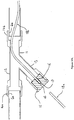
- Figure 5
- is a schematic view illustrating the transition of a trunk cable between sewer and trench.
- Referring now to
figures 1 and2 , abuilding 1 is situated in the vicinity of a public roadway 2. Alongside the public roadway 2 are laid a water main (not shown) and atrunk cable 4. An individual property water supply pipe 6 branches off the water main to enter thebuilding 1. The pipe 6 thus provides a supply of water for use withinbuilding 1. The flow of water within the pipe 6 is controlled bypavement stopcock 3 provided within a covered hole 3a andbuilding stopcock 5 provided withinbuilding 1. - Similarly, at junction box 7 a branch cable branches off
trunk cable 4 and continues to enterbuilding 1. The branch cable thus provides a connection between one or more nodes inbuilding 1 and external nodes connected directly or indirectly totrunk cable 4. - The
trunk cable 4 may be laid along a dedicated conduit or a convenient length of sewer, water supply pipe or storm drain as appropriate. Thetrunk cable 4 is typically part of a network comprising one ormore trunk cables 4 wherein the or eachtrunk cable 4 is laid along dedicated conduit and/or convenient lengths of sewer, water supply pipe or storm drain as required. -
Figure 5 illustrates schematically, how atrunk cable 4 may pass between a sewer branch 101 (for example) and atrench 104. TheTrench 104 may enable thecable 4 to exit thesewer 101 and travel to thejunction box 7. In the drawing, thecable 4 is shown fixed to the side of thesewer 101, however it need not be fixed there and may in alternative solutions be fixed or laid freely in another position within thesewer 101. Thecable 4 exits thesewer branch 101 along an access shaft 109 and then along aduct 111 intotrench 104. In the example shown, the access shaft 109 is provided with acover 110 and is situated in roadway 2. - In order to prevent the escape of noxious gases from the
sewer 101 alongduct 111, suitable sealing means 113 may be provided. The sealing means 113 is adapted to form a substantially airtight seal between its exterior surface and the interior surface ofduct 111, as is shown infigures 4a and 4b . The sealing means 113 is also provided with a central passageway through whichtrunk cable 4 may pass. The passageway is adapted to form a substantially airtight seal around thetrunk cable 4. The sealing means 113 is formed from a resiliently deformable material, such that it can compensate for small irregularities on its exterior, on the interior of theduct 111, on the passageway or on thetrunk cable 4, to maintain a seal. In some embodiments, a suitable adhesive, such as an epoxy resin, may be applied to the exterior to help retain the sealing means 113 withinduct 111. Additionally or alternatively, the adhesive may be applied in the passageway aroundcable 105 to help retain thetrunk cable 4 in place. The adhesive may also help maintain a substantially airtight seal where it is applied. - In a conventional scenario, the water supply pipe 6 is provided at the time of construction of the
building 1 and is an underground pipe (as is the main). The cable may however be provided much later. As such, it is conventional to provide a dedicated (and usually underground) conduit for cable. This can however be expensive and disruptive. This may be a particular problem if the cable has to cross a garden 1a that the owner of building 1 is loathe to see disturbed. - Accordingly, in the present invention the cable is laid along water supply pipe 6. This allows the cable to cross between the
trunk cable 4 and thebuilding 1 with minimal disturbance of the ground therebetween. This is achieved by introducing cable to pipe 6 by use of a suitable Y-junction 10 at location 10a and removing the cable from the pipe 6 by use of a second such Y-junction 10 at location 10b, It is of course alternatively possible to lay the cable in any other convenient length of pre-existing pipe such as a waste water pipe or a sewer. - In the event that the
junction box 7 is not provided directly adjacent to the covered hole 3a, amicrotrench 8 may be provided to carry the cable fromjunction box 7. Themicrotrench 8 may comprise a filled trench with the cable at its base. The filled trench may have a depth of say 150mm or so and a width of say 20-30mm or so. - Turning now to
figure 3a , the Y-junction 10 comprises a leg 11 and twoarms arm 12 are aligned along a common axis.Arm 13 projects from the Y-junction at a small angle to the common axis. The ends of leg 11 and are 12 are open and provided with compression fittings 14a, 14b. These allow the Y-junction to be fitted to open ends 6a, 6b facing a gap 6g in water supply pipe 6. When connected thus, a water flow path is provided between 6a and 6b along leg 11 andarm 12. - The
arm 13 is capped with anend cap 15. Theend cap 15 additionally incorporates acable passage 16 which allows a cable to pass therethrough. In the illustrated comparative example, the cable is provided within amicroduct tube 18. The microduct tube has separate sections (here labelled 18a and 18b) on either side of theend cap 15. Anarrow neck 17 is provided with a small hole through which the cable rather than themicroduct tube 18 can pass. Theend cap 15 and thecable passage 16 may be formed of or lined with a resilient material such that it forms a seal with the walls ofarm 13 and a seal around the microduct tubes 18a, 18b, thus preventing the escape of water. In order to facilitate this, the diameter of thecable passage 16 may be matched to the expected diameter of the microduct tubes 18a, 18b. - A number of variations on the basic structure of the Y-junction 10 are possible. In particular, these might relate to the projecting
arm 13 and the end closure thereof. Turning tofigure 3b , theend closure 25 is a simple bung having a cable passage 26 therethrough, which allows a cable within amicroduct tube 18 to pass therethrough. The bung 25 and the cable passage 26 may be formed of or lined with a resilient material such that it forms a seal with the walls ofarm 13 and a seal around themicroduct tube 18 thus preventing the escape of water. In order to facilitate this, the diameter of the cable passage 26 may be matched to the expected diameter of themicroduct tube 18. Theexample bung 25 illustrated is provided with a threadedouter surface 25a adapted to interconnect with a thread 13a provided on projectingarm 13. It is of course possible that a bung 25 without such a thread may be substituted if desired. - In
figure 3c a morecomplex closure arrangement 35 is shown. In such an example, anend cap 38 is retained in position by asleeve 34. thesleeve 34 is provided with a thread 33b which engages with a thread 13b provided on the outside of the projectingarm 13. Theend cap 38 has apassage 36 which allows a cable to pass therethrough. In the illustrated comparative example, the cable is provided within amicroduct tube 18. The microduct tube has separate sections (here labelled 18a and 18b) on either side of theend cap 38. Anarrow neck 37 is provided with a small hole through which the cable rather than themicroduct tube 18 can pass. Theend cap 38 and thecable passage 16 may be formed of or lined with a resilient material such that it forms a seal with the walls ofarm 13 and a seal around the microduct tubes 18a, 18b, thus preventing the escape of water. In order to facilitate this, the diameter of thecable passage 36 may be matched to the expected diameter of the microduct tubes 18a, 18b. Additionally, barbs or wedge projections 38a, 38b may be provided to engage the microduct tubes 18a, 18b and help maintain them in position. Furthermore, an O-ring 39 may be provided to improve the seal. - An embodiment of the invention is shown in
figure 3d . In this embodiment, thearm 13 is of considerably narrower diameter thanarms 11, 12, such that it tightly encloses acable passage 46 in the form of a duct adapted to fit aroundmicroduct 18. Themicroduct 18 enters and leaves thecable passage 46 via ends 45. The ends 45 are provided with barbed or wedged projections to improve the sealing and help retain themicroduct 18 securely in position. - In some versions of the above comparative examples and the embodiment, the
cable passage microduct tubes 18 or a plurality ofcable passages single microduct tube 18 from a bundle ofmicroduct tubes 18. - The
microduct tube 18 is typically of around say 4mm in diameter and is formed of an inert material such as HDPE (high density polyethylene) or similar. This prevents the water in pipe 6 being contaminated by themicroduct tube 18 and prevents the water affecting the transmission of data along cable. The cable within themicroduct tube 18 is typically an optical fibre and may be a multicore optical fibre. Such a cable having say 2-4 cores might have an external diameter in the range 2-3mm - In alternative comparative examples, a cable provided with a suitable inert insulating coating may be directly inserted through a
suitable cable passage 16 and themicroduct tubes 18 omitted. The cable is typically an optical fibre and may be a multicore optical fibre. Such an insulated cable having say 2-4 cores might have an external diameter in the range 2-5mm. - In order to allow cable to be laid along pipe 6, a method according to the present invention may be used. The method comprises the steps of turning off the water supply to pipe 6 using
stopcocks building 1 at location 10b to leave a second gap 6g. In alternative embodiments, if thebuilding 1 has a suitable form such as a cellar wherein the pipe 6 is exposed this location may be within thebuilding 1. - A cable is then laid along the section of pipe 6 between 10a and 10b, either directly or through a microduct tube 18b. Y-junctions 10 are inserted in the gaps 6g in pipe 6. The cable is threaded through the
cable passages 16 provided in the end caps 15. The Y-junctions 10 are then sealed on to the ends of the pipe 6a, 6b facing the gaps using compression fixtures 14a, 14b. At this point the water supply to the pipe 6 can be switched back on. - One end of the cable may then be connected to
cable junction box 7 provided adjacent to or in the path oftrunk cable 4. The other end of the cable may then be connected to suitable equipment within thebuilding 1. In many cases, the cable may be removed from the pipe 6 outside but adjacent to thebuilding 1 and enter thebuilding 1 through a suitable hole provided in an external wall. - It is of course to be understood that the invention is not to be restricted to the details of the above embodiment which has been described by way of example only.
Claims (19)
- A method of laying a branch cable between a trunk cable and a desired node location comprising the steps of: locating a pre-existing supply, drain, waste water or sewage pipe (6) for the node location adjacent to the trunk cable (4); introducing the branch cable into the pre-existing pipe (6); passing the branch cable along the pre-existing pipe (6); and removing the branch cable from the pre-existing pipe (6) adjacent to the node location; the introduction or removal of the cable from the pre-existing pipe (6) being enabled by the provision of a cable transfer means, said cable transfer means comprising: a Y-junction (10) inserted into a gap provided in the pre-existing pipe (6), the Y-junction (10) comprising a leg (11) and one arm (12) having open ends adapted to be connected to the pre-existing pipe (6), and another arm (13);
wherein the cable is threaded along a microduct tube (18) and wherein the other arm (13) is of considerably narrower diameter than the open arm (12) and the leg (11) such that it tightly encloses a cable passage (46) in the form of a duct adapted to fit around the microduct tube (18) to prevent the passage of water alongside said microduct tube (18), and wherein the microduct (18) enters and leaves the cable passage (46) via ends (45), the ends (45) provided with barbed or wedged projections to improve the sealing and help restrain the microduct tube (18) securely in position. - A method as claimed in claim 1 wherein the method comprises the step of connecting the branch cable to the trunk cable (4) either directly or via a suitable junction box (7) and/or the step of connecting the branch cable to the node.
- A method as claimed in claim 2 wherein the branch cable enters the pre-existing pipe (6) adjacent to the junction box (7) or wherein the branch cable travels along a suitable conduit such as a microtrench (8) or other conventional conduit between the junction box (7) and the pre-existing pipe (6).
- A method as claimed in claim 2 or claim 3 wherein the branch cable is connected directly to suitable equipment at the node or is connected to a junction box (7) or socket allowing one or more devices to be connected to a network.
- A method as claimed in any one of claims 2 to 4 wherein the cable is removed from the pre-existing pipe (6) adjacent to a building within which the node is provided and the cable is passed through a suitable entry passageway to be connected to the node within the building.
- A method as claimed in any one of claims 2 to 4 wherein the cable is removed from the pre-existing pipe (6) within a building within which the node is provided.
- A method as claimed in claim 6 wherein the cable enters and/or leaves the pre-existing pipe (6) between a mains side stopcock and a dedicated building stopcock.
- A method as claimed in any preceding claim wherein the open leg (11) and arm (12) of the Y-junction (10) are connected to the pre-existing pipe (6) via suitable fittings (14a, 14b) adapted to seal the Y-junction (10) to the pre-existing pipe.
- A method as claimed in any preceding claim wherein the method incorporates the step of forming a suitable gap (6g) in the pre-existing pipe (6).
- A method as claimed in claim 9 wherein the gap (6g) is formed by use of cutting equipment.
- A method as claimed in any preceding claim wherein the trunk cable is laid according a method comprising the steps of: laying a cable through one or more lengths of sewer between the two points; and where there is no convenient length of sewer or a gap between convenient lengths of sewer, providing a length of dedicated cable conduit between said lengths of sewer and laying said cable through said dedicated cable conduit.
- A method as claimed in claim 11 wherein the trunk cable is laid through the sewer using techniques including, but are not limited to: laying the cable loose in the flow channel of the sewer; pinning the cable to the walls of the sewer; or passing the cable through a duct provided in the sewer.
- A method as claimed in claim 12 wherein if the method involves laying the cable loose in the flow channel of a sewer, the method includes the step of installing a suitable cable guide at points wherein the cable is desired or required to enter or leave the flow channel and/or the step of installing such cable guides at points wherein the cable is required to enter or leave the sewer and on either side of points such as junctions or bends in the sewer wherein a cable in the flow channel is likely to lie across the direction of flow.
- A method as claimed in any one of claims 11 to 13 wherein the cable conduit is provided by a technique involving: digging a trench, laying the cable in the trench and filling the trench.
- A method as claimed in any one of claims 11 to 14 wherein sealing means (113) are provided at points wherein the cable exits a sewer, to prevent the escape of noxious gases from the sewer or are provided at both ends of a duct carrying the cable between the sewer and the dedicated conduit.
- A cable transfer means suitable for introducing or removing a cable from a pre-existing water supply, drain, waste water or sewage pipe (6) comprising: Y-junction (10) having a leg (11) having an open end adapted to be connected to a pre-existing pipe (6); one arm (12) having an open end adapted to be connected to a pre-existing pipe (6); and another arm (13), wherein the cable is threaded along a microduct tube (18),
the cable transfer means further comprising a cable passage (46) in the form of a duct;
wherein the other arm (13) is of considerably narrower diameter than the open arm (12) and the leg (11),
characterised in that the other arm (13) tightly encloses the cable passage (46) in the form of a duct adapted to fit around the microduct tube (18) to prevent the passage of water alongside said microduct tube (18), and wherein the microduct tube (18) enters and leaves the cable passage (46) via ends (45), the ends (45) provided with barbed or wedged projections to improve the sealing and help restrain the microduct tube (18) securely in position. - A cable transfer means as claimed in claim 16 wherein the open arm (12) and the leg (11) of the Y-junction (10) are provided in along a common linear axis.
- A cable transfer means as claimed in any one of claims 16 to 17 wherein the cable passage (46) is adapted to allow the passage of a bundle of microduct tubes (18).
- A cable transfer means as claimed in any one of claims 16 to 18 wherein the open leg (11) and arm (12) of the Y-junction (10) are connected to the pre-existing pipe (6) via fittings (14a, 14b) adapted to seal the Y-junction (10) to the pre-existing pipe (6).
Applications Claiming Priority (2)
| Application Number | Priority Date | Filing Date | Title |
|---|---|---|---|
| GBGB0816616.7A GB0816616D0 (en) | 2008-09-11 | 2008-09-11 | Laying network cables in water supply pipes |
| PCT/GB2009/051172 WO2010029365A2 (en) | 2008-09-11 | 2009-09-11 | Laying network cables in water supply pipes |
Publications (2)
| Publication Number | Publication Date |
|---|---|
| EP2338213A2 EP2338213A2 (en) | 2011-06-29 |
| EP2338213B1 true EP2338213B1 (en) | 2019-08-21 |
Family
ID=39929986
Family Applications (1)
| Application Number | Title | Priority Date | Filing Date |
|---|---|---|---|
| EP09785627.2A Not-in-force EP2338213B1 (en) | 2008-09-11 | 2009-09-11 | Laying network cables in water supply pipes |
Country Status (7)
| Country | Link |
|---|---|
| US (1) | US8695214B2 (en) |
| EP (1) | EP2338213B1 (en) |
| AU (1) | AU2009290647B2 (en) |
| GB (2) | GB0816616D0 (en) |
| NZ (1) | NZ592205A (en) |
| WO (1) | WO2010029365A2 (en) |
| ZA (1) | ZA201102664B (en) |
Families Citing this family (7)
| Publication number | Priority date | Publication date | Assignee | Title |
|---|---|---|---|---|
| DE102010031978A1 (en) * | 2010-07-22 | 2012-01-26 | Ewe Netz Gmbh | line system |
| CN103379163B (en) * | 2012-04-25 | 2016-04-06 | 阿里巴巴集团控股有限公司 | A kind of defining method of business object and determining device |
| GB2522230A (en) * | 2014-01-17 | 2015-07-22 | Deflux Holdings Ltd | Method and apparatus for removing a cable core from a cable sheath |
| GB2547405A (en) * | 2015-11-16 | 2017-08-23 | Craley Group Ltd | A pipe connector fitting |
| CN109737271A (en) * | 2019-02-28 | 2019-05-10 | 西安石油大学 | A kind of flexible anode mounting structure for pipeline internal corrosion |
| IT202000021091A1 (en) * | 2020-09-07 | 2022-03-07 | Orazio Fiume | METHOD AND SYSTEM OF POWER SUPPLY OF A FAN COIL |
| US11621502B2 (en) * | 2020-09-10 | 2023-04-04 | Baker Hughes Oilfield Operations Llc | Hybrid cable crimp |
Citations (1)
| Publication number | Priority date | Publication date | Assignee | Title |
|---|---|---|---|---|
| US20030068143A1 (en) * | 2001-10-10 | 2003-04-10 | Eric Martinez | Method and apparatus providing fiber optic cables through gas service pipes |
Family Cites Families (10)
| Publication number | Priority date | Publication date | Assignee | Title |
|---|---|---|---|---|
| DE3140928C2 (en) * | 1981-10-15 | 1989-12-14 | Otto Niedung KG, 3000 Hannover | Device for the subsequent pulling in of telecommunication cables |
| GB2267005A (en) | 1992-05-15 | 1993-11-17 | Delta Technical Services Ltd | Data transmission |
| NL1001961C2 (en) | 1995-12-21 | 1997-06-24 | Nederland Ptt | A method of installing a tubing with taps for telecommunication cables, as well as a tapping element for use in that method. |
| DE19734274B4 (en) * | 1997-08-07 | 2010-04-08 | Norddeutsche Seekabelwerke Gmbh & Co. Kg | Communication network with fiber-optic cables between subscribers and communication centers in existing supply lines |
| US6019351A (en) | 1998-01-15 | 2000-02-01 | Vikimatic Sales, Inc. | Method and apparatus for introducing a cable into a conduit |
| JP3574895B2 (en) | 2000-01-26 | 2004-10-06 | 智美 中村 | Rainwater communication line |
| WO2001092921A2 (en) * | 2000-06-01 | 2001-12-06 | Bbnt Solutions Llc | A system and method for deploying fiber optic networks through water distribution systems |
| US6584252B1 (en) * | 2000-12-14 | 2003-06-24 | Cisco Technology, Inc. | Method and system for providing fiber optic cable to end users |
| US20020114595A1 (en) * | 2001-02-16 | 2002-08-22 | Hanan Potash | Efficient method and system for the installation of data conduit in pre-existing structures |
| GB0614416D0 (en) * | 2006-07-20 | 2006-08-30 | Thomas Elfed | Laying network cables in sewers |
-
2008
- 2008-09-11 GB GBGB0816616.7A patent/GB0816616D0/en not_active Ceased
-
2009
- 2009-09-11 WO PCT/GB2009/051172 patent/WO2010029365A2/en active Application Filing
- 2009-09-11 EP EP09785627.2A patent/EP2338213B1/en not_active Not-in-force
- 2009-09-11 NZ NZ592205592205A patent/NZ592205A/en not_active IP Right Cessation
- 2009-09-11 AU AU2009290647A patent/AU2009290647B2/en not_active Ceased
- 2009-09-11 GB GB0915955.9A patent/GB2463372B/en active Active
- 2009-09-11 US US13/063,493 patent/US8695214B2/en active Active
-
2011
- 2011-04-11 ZA ZA2011/02664A patent/ZA201102664B/en unknown
Patent Citations (1)
| Publication number | Priority date | Publication date | Assignee | Title |
|---|---|---|---|---|
| US20030068143A1 (en) * | 2001-10-10 | 2003-04-10 | Eric Martinez | Method and apparatus providing fiber optic cables through gas service pipes |
Also Published As
| Publication number | Publication date |
|---|---|
| GB2463372B (en) | 2013-02-13 |
| AU2009290647A1 (en) | 2010-03-18 |
| GB2463372A (en) | 2010-03-17 |
| US20120012386A1 (en) | 2012-01-19 |
| US8695214B2 (en) | 2014-04-15 |
| ZA201102664B (en) | 2012-01-25 |
| GB0816616D0 (en) | 2008-10-22 |
| AU2009290647B2 (en) | 2015-05-21 |
| EP2338213A2 (en) | 2011-06-29 |
| NZ592205A (en) | 2013-06-28 |
| GB0915955D0 (en) | 2009-10-28 |
| WO2010029365A2 (en) | 2010-03-18 |
| WO2010029365A3 (en) | 2010-05-06 |
Similar Documents
| Publication | Publication Date | Title |
|---|---|---|
| EP2338213B1 (en) | Laying network cables in water supply pipes | |
| CA2372678C (en) | Method for laying data cables and data transmission device for a communal gas, pressure or waste-water pipe system comprising at least one waste-water drain and a service shaft | |
| JP3833267B2 (en) | Fiber optic cable network | |
| US20030068143A1 (en) | Method and apparatus providing fiber optic cables through gas service pipes | |
| US20010010781A1 (en) | Method of laying data cables and the like in underground pipes and pipe-cable combinations | |
| AU2007274866B2 (en) | Laying network cables in sewers | |
| EP2064789B1 (en) | Laying network cables in sewers | |
| EP2594000B1 (en) | Watertight cable connections | |
| US8864107B2 (en) | Laying network cables in sewers | |
| JPH03270613A (en) | Method for underground wiring of communication wire by using fluid transport pipe | |
| AU2006200987B2 (en) | Subsurface fibre optic cable network installation | |
| MX2012009653A (en) | Duct system for fibre optic components. | |
| Anderson | CIPP Process: Installation of Fiber Optic Cables in Sewers | |
| JPH10290517A (en) | Manhole for communication cable | |
| WO2015001332A1 (en) | An improved cable transfer system | |
| EP2166394B1 (en) | Slab assembly for underground vault | |
| KR20020084866A (en) | The pipe waterproof method | |
| MXPA00012824A (en) | Method for laying data cables and data transmission device fora communal gas, pressure or waste-water pipe system comprising at least one waste-water drain and a service shaft | |
| JP2000347078A (en) | Structure of optical fiber cable branching part laid within sewage pipe line | |
| JPH08338061A (en) | Construction method for information communications network utilizing existing covered conduit |
Legal Events
| Date | Code | Title | Description |
|---|---|---|---|
| PUAI | Public reference made under article 153(3) epc to a published international application that has entered the european phase |
Free format text: ORIGINAL CODE: 0009012 |
|
| 17P | Request for examination filed |
Effective date: 20110411 |
|
| AK | Designated contracting states |
Kind code of ref document: A2 Designated state(s): AT BE BG CH CY CZ DE DK EE ES FI FR GB GR HR HU IE IS IT LI LT LU LV MC MK MT NL NO PL PT RO SE SI SK SM TR |
|
| AX | Request for extension of the european patent |
Extension state: AL BA RS |
|
| DAX | Request for extension of the european patent (deleted) | ||
| RAP1 | Party data changed (applicant data changed or rights of an application transferred) |
Owner name: CMS (CABLE MANAGEMENT SUPPLIES) PLC |
|
| 17Q | First examination report despatched |
Effective date: 20140311 |
|
| RAP1 | Party data changed (applicant data changed or rights of an application transferred) |
Owner name: CRALEY GROUP LIMITED |
|
| STAA | Information on the status of an ep patent application or granted ep patent |
Free format text: STATUS: EXAMINATION IS IN PROGRESS |
|
| GRAP | Despatch of communication of intention to grant a patent |
Free format text: ORIGINAL CODE: EPIDOSNIGR1 |
|
| STAA | Information on the status of an ep patent application or granted ep patent |
Free format text: STATUS: GRANT OF PATENT IS INTENDED |
|
| RIC1 | Information provided on ipc code assigned before grant |
Ipc: G02B 6/44 20060101ALI20181207BHEP Ipc: H02G 9/06 20060101ALI20181207BHEP Ipc: G02B 6/50 20060101ALI20181207BHEP Ipc: H02G 1/08 20060101AFI20181207BHEP |
|
| INTG | Intention to grant announced |
Effective date: 20190109 |
|
| RBV | Designated contracting states (corrected) |
Designated state(s): AT BE BG CH CY CZ DE DK EE ES FI FR GR HR HU IE IS IT LI LT LU LV MC MK MT NL NO PL PT RO SE SI SK SM TR |
|
| GRAS | Grant fee paid |
Free format text: ORIGINAL CODE: EPIDOSNIGR3 |
|
| GRAA | (expected) grant |
Free format text: ORIGINAL CODE: 0009210 |
|
| STAA | Information on the status of an ep patent application or granted ep patent |
Free format text: STATUS: THE PATENT HAS BEEN GRANTED |
|
| AK | Designated contracting states |
Kind code of ref document: B1 Designated state(s): AT BE BG CH CY CZ DE DK EE ES FI FR GR HR HU IE IS IT LI LT LU LV MC MK MT NL NO PL PT RO SE SI SK SM TR |
|
| REG | Reference to a national code |
Ref country code: CH Ref legal event code: EP |
|
| REG | Reference to a national code |
Ref country code: DE Ref legal event code: R096 Ref document number: 602009059556 Country of ref document: DE |
|
| REG | Reference to a national code |
Ref country code: AT Ref legal event code: REF Ref document number: 1170828 Country of ref document: AT Kind code of ref document: T Effective date: 20190915 |
|
| REG | Reference to a national code |
Ref country code: IE Ref legal event code: FG4D |
|
| REG | Reference to a national code |
Ref country code: LT Ref legal event code: MG4D |
|
| REG | Reference to a national code |
Ref country code: NL Ref legal event code: MP Effective date: 20190821 |
|
| PG25 | Lapsed in a contracting state [announced via postgrant information from national office to epo] |
Ref country code: FI Free format text: LAPSE BECAUSE OF FAILURE TO SUBMIT A TRANSLATION OF THE DESCRIPTION OR TO PAY THE FEE WITHIN THE PRESCRIBED TIME-LIMIT Effective date: 20190821 Ref country code: PT Free format text: LAPSE BECAUSE OF FAILURE TO SUBMIT A TRANSLATION OF THE DESCRIPTION OR TO PAY THE FEE WITHIN THE PRESCRIBED TIME-LIMIT Effective date: 20191223 Ref country code: HR Free format text: LAPSE BECAUSE OF FAILURE TO SUBMIT A TRANSLATION OF THE DESCRIPTION OR TO PAY THE FEE WITHIN THE PRESCRIBED TIME-LIMIT Effective date: 20190821 Ref country code: SE Free format text: LAPSE BECAUSE OF FAILURE TO SUBMIT A TRANSLATION OF THE DESCRIPTION OR TO PAY THE FEE WITHIN THE PRESCRIBED TIME-LIMIT Effective date: 20190821 Ref country code: BG Free format text: LAPSE BECAUSE OF FAILURE TO SUBMIT A TRANSLATION OF THE DESCRIPTION OR TO PAY THE FEE WITHIN THE PRESCRIBED TIME-LIMIT Effective date: 20191121 Ref country code: NL Free format text: LAPSE BECAUSE OF FAILURE TO SUBMIT A TRANSLATION OF THE DESCRIPTION OR TO PAY THE FEE WITHIN THE PRESCRIBED TIME-LIMIT Effective date: 20190821 Ref country code: LT Free format text: LAPSE BECAUSE OF FAILURE TO SUBMIT A TRANSLATION OF THE DESCRIPTION OR TO PAY THE FEE WITHIN THE PRESCRIBED TIME-LIMIT Effective date: 20190821 Ref country code: NO Free format text: LAPSE BECAUSE OF FAILURE TO SUBMIT A TRANSLATION OF THE DESCRIPTION OR TO PAY THE FEE WITHIN THE PRESCRIBED TIME-LIMIT Effective date: 20191121 |
|
| PGFP | Annual fee paid to national office [announced via postgrant information from national office to epo] |
Ref country code: DE Payment date: 20191118 Year of fee payment: 11 |
|
| PG25 | Lapsed in a contracting state [announced via postgrant information from national office to epo] |
Ref country code: ES Free format text: LAPSE BECAUSE OF FAILURE TO SUBMIT A TRANSLATION OF THE DESCRIPTION OR TO PAY THE FEE WITHIN THE PRESCRIBED TIME-LIMIT Effective date: 20190821 Ref country code: LV Free format text: LAPSE BECAUSE OF FAILURE TO SUBMIT A TRANSLATION OF THE DESCRIPTION OR TO PAY THE FEE WITHIN THE PRESCRIBED TIME-LIMIT Effective date: 20190821 Ref country code: IS Free format text: LAPSE BECAUSE OF FAILURE TO SUBMIT A TRANSLATION OF THE DESCRIPTION OR TO PAY THE FEE WITHIN THE PRESCRIBED TIME-LIMIT Effective date: 20191221 Ref country code: GR Free format text: LAPSE BECAUSE OF FAILURE TO SUBMIT A TRANSLATION OF THE DESCRIPTION OR TO PAY THE FEE WITHIN THE PRESCRIBED TIME-LIMIT Effective date: 20191122 |
|
| PGFP | Annual fee paid to national office [announced via postgrant information from national office to epo] |
Ref country code: FR Payment date: 20191128 Year of fee payment: 11 |
|
| REG | Reference to a national code |
Ref country code: AT Ref legal event code: MK05 Ref document number: 1170828 Country of ref document: AT Kind code of ref document: T Effective date: 20190821 |
|
| PG25 | Lapsed in a contracting state [announced via postgrant information from national office to epo] |
Ref country code: TR Free format text: LAPSE BECAUSE OF FAILURE TO SUBMIT A TRANSLATION OF THE DESCRIPTION OR TO PAY THE FEE WITHIN THE PRESCRIBED TIME-LIMIT Effective date: 20190821 |
|
| PG25 | Lapsed in a contracting state [announced via postgrant information from national office to epo] |
Ref country code: IT Free format text: LAPSE BECAUSE OF FAILURE TO SUBMIT A TRANSLATION OF THE DESCRIPTION OR TO PAY THE FEE WITHIN THE PRESCRIBED TIME-LIMIT Effective date: 20190821 Ref country code: EE Free format text: LAPSE BECAUSE OF FAILURE TO SUBMIT A TRANSLATION OF THE DESCRIPTION OR TO PAY THE FEE WITHIN THE PRESCRIBED TIME-LIMIT Effective date: 20190821 Ref country code: PL Free format text: LAPSE BECAUSE OF FAILURE TO SUBMIT A TRANSLATION OF THE DESCRIPTION OR TO PAY THE FEE WITHIN THE PRESCRIBED TIME-LIMIT Effective date: 20190821 Ref country code: RO Free format text: LAPSE BECAUSE OF FAILURE TO SUBMIT A TRANSLATION OF THE DESCRIPTION OR TO PAY THE FEE WITHIN THE PRESCRIBED TIME-LIMIT Effective date: 20190821 Ref country code: AT Free format text: LAPSE BECAUSE OF FAILURE TO SUBMIT A TRANSLATION OF THE DESCRIPTION OR TO PAY THE FEE WITHIN THE PRESCRIBED TIME-LIMIT Effective date: 20190821 Ref country code: DK Free format text: LAPSE BECAUSE OF FAILURE TO SUBMIT A TRANSLATION OF THE DESCRIPTION OR TO PAY THE FEE WITHIN THE PRESCRIBED TIME-LIMIT Effective date: 20190821 |
|
| PG25 | Lapsed in a contracting state [announced via postgrant information from national office to epo] |
Ref country code: CZ Free format text: LAPSE BECAUSE OF FAILURE TO SUBMIT A TRANSLATION OF THE DESCRIPTION OR TO PAY THE FEE WITHIN THE PRESCRIBED TIME-LIMIT Effective date: 20190821 Ref country code: SK Free format text: LAPSE BECAUSE OF FAILURE TO SUBMIT A TRANSLATION OF THE DESCRIPTION OR TO PAY THE FEE WITHIN THE PRESCRIBED TIME-LIMIT Effective date: 20190821 Ref country code: SM Free format text: LAPSE BECAUSE OF FAILURE TO SUBMIT A TRANSLATION OF THE DESCRIPTION OR TO PAY THE FEE WITHIN THE PRESCRIBED TIME-LIMIT Effective date: 20190821 Ref country code: MC Free format text: LAPSE BECAUSE OF FAILURE TO SUBMIT A TRANSLATION OF THE DESCRIPTION OR TO PAY THE FEE WITHIN THE PRESCRIBED TIME-LIMIT Effective date: 20190821 Ref country code: IS Free format text: LAPSE BECAUSE OF FAILURE TO SUBMIT A TRANSLATION OF THE DESCRIPTION OR TO PAY THE FEE WITHIN THE PRESCRIBED TIME-LIMIT Effective date: 20200224 |
|
| REG | Reference to a national code |
Ref country code: CH Ref legal event code: PL |
|
| REG | Reference to a national code |
Ref country code: DE Ref legal event code: R097 Ref document number: 602009059556 Country of ref document: DE |
|
| PLBE | No opposition filed within time limit |
Free format text: ORIGINAL CODE: 0009261 |
|
| STAA | Information on the status of an ep patent application or granted ep patent |
Free format text: STATUS: NO OPPOSITION FILED WITHIN TIME LIMIT |
|
| PG2D | Information on lapse in contracting state deleted |
Ref country code: IS |
|
| PG25 | Lapsed in a contracting state [announced via postgrant information from national office to epo] |
Ref country code: LI Free format text: LAPSE BECAUSE OF NON-PAYMENT OF DUE FEES Effective date: 20190930 Ref country code: CH Free format text: LAPSE BECAUSE OF NON-PAYMENT OF DUE FEES Effective date: 20190930 Ref country code: IE Free format text: LAPSE BECAUSE OF NON-PAYMENT OF DUE FEES Effective date: 20190911 Ref country code: LU Free format text: LAPSE BECAUSE OF NON-PAYMENT OF DUE FEES Effective date: 20190911 |
|
| REG | Reference to a national code |
Ref country code: BE Ref legal event code: MM Effective date: 20190930 |
|
| 26N | No opposition filed |
Effective date: 20200603 |
|
| PG25 | Lapsed in a contracting state [announced via postgrant information from national office to epo] |
Ref country code: BE Free format text: LAPSE BECAUSE OF NON-PAYMENT OF DUE FEES Effective date: 20190930 Ref country code: SI Free format text: LAPSE BECAUSE OF FAILURE TO SUBMIT A TRANSLATION OF THE DESCRIPTION OR TO PAY THE FEE WITHIN THE PRESCRIBED TIME-LIMIT Effective date: 20190821 |
|
| REG | Reference to a national code |
Ref country code: DE Ref legal event code: R119 Ref document number: 602009059556 Country of ref document: DE |
|
| PG25 | Lapsed in a contracting state [announced via postgrant information from national office to epo] |
Ref country code: CY Free format text: LAPSE BECAUSE OF FAILURE TO SUBMIT A TRANSLATION OF THE DESCRIPTION OR TO PAY THE FEE WITHIN THE PRESCRIBED TIME-LIMIT Effective date: 20190821 |
|
| PG25 | Lapsed in a contracting state [announced via postgrant information from national office to epo] |
Ref country code: FR Free format text: LAPSE BECAUSE OF NON-PAYMENT OF DUE FEES Effective date: 20200930 Ref country code: HU Free format text: LAPSE BECAUSE OF FAILURE TO SUBMIT A TRANSLATION OF THE DESCRIPTION OR TO PAY THE FEE WITHIN THE PRESCRIBED TIME-LIMIT; INVALID AB INITIO Effective date: 20090911 Ref country code: MT Free format text: LAPSE BECAUSE OF FAILURE TO SUBMIT A TRANSLATION OF THE DESCRIPTION OR TO PAY THE FEE WITHIN THE PRESCRIBED TIME-LIMIT Effective date: 20190821 Ref country code: DE Free format text: LAPSE BECAUSE OF NON-PAYMENT OF DUE FEES Effective date: 20210401 |
|
| PG25 | Lapsed in a contracting state [announced via postgrant information from national office to epo] |
Ref country code: MK Free format text: LAPSE BECAUSE OF FAILURE TO SUBMIT A TRANSLATION OF THE DESCRIPTION OR TO PAY THE FEE WITHIN THE PRESCRIBED TIME-LIMIT Effective date: 20190821 |