EP2337520B1 - Vorrichtung zur stabilisierung von amputationen - Google Patents
Vorrichtung zur stabilisierung von amputationen Download PDFInfo
- Publication number
- EP2337520B1 EP2337520B1 EP09816885.9A EP09816885A EP2337520B1 EP 2337520 B1 EP2337520 B1 EP 2337520B1 EP 09816885 A EP09816885 A EP 09816885A EP 2337520 B1 EP2337520 B1 EP 2337520B1
- Authority
- EP
- European Patent Office
- Prior art keywords
- bone
- intramedullary
- base plate
- amputation
- amputated
- Prior art date
- Legal status (The legal status is an assumption and is not a legal conclusion. Google has not performed a legal analysis and makes no representation as to the accuracy of the status listed.)
- Not-in-force
Links
- 238000002266 amputation Methods 0.000 title claims description 45
- 230000006641 stabilisation Effects 0.000 title claims description 29
- 238000011105 stabilization Methods 0.000 title claims description 29
- 210000000988 bone and bone Anatomy 0.000 claims description 68
- 210000002082 fibula Anatomy 0.000 claims description 43
- 210000002303 tibia Anatomy 0.000 claims description 43
- 239000007943 implant Substances 0.000 claims description 40
- 238000003780 insertion Methods 0.000 claims description 28
- 230000037431 insertion Effects 0.000 claims description 28
- 230000009977 dual effect Effects 0.000 claims description 27
- 210000003414 extremity Anatomy 0.000 claims description 14
- 210000002414 leg Anatomy 0.000 claims description 9
- 239000002639 bone cement Substances 0.000 claims description 8
- 210000000245 forearm Anatomy 0.000 claims description 6
- 230000033001 locomotion Effects 0.000 claims description 6
- 230000007246 mechanism Effects 0.000 claims description 6
- 210000000623 ulna Anatomy 0.000 claims description 5
- 229920000642 polymer Polymers 0.000 claims description 4
- 238000000926 separation method Methods 0.000 claims description 4
- 230000007423 decrease Effects 0.000 claims description 3
- 230000008468 bone growth Effects 0.000 claims description 2
- 210000000707 wrist Anatomy 0.000 claims description 2
- 230000000087 stabilizing effect Effects 0.000 claims 25
- 230000001788 irregular Effects 0.000 claims 2
- 239000000463 material Substances 0.000 description 6
- 210000004872 soft tissue Anatomy 0.000 description 6
- 230000008901 benefit Effects 0.000 description 5
- 230000000399 orthopedic effect Effects 0.000 description 5
- 239000002184 metal Substances 0.000 description 4
- 229910052751 metal Inorganic materials 0.000 description 4
- 238000000034 method Methods 0.000 description 4
- 208000027418 Wounds and injury Diseases 0.000 description 3
- 230000006378 damage Effects 0.000 description 3
- 201000010099 disease Diseases 0.000 description 3
- 208000037265 diseases, disorders, signs and symptoms Diseases 0.000 description 3
- 208000014674 injury Diseases 0.000 description 3
- 239000000758 substrate Substances 0.000 description 3
- 210000001519 tissue Anatomy 0.000 description 3
- 206010031252 Osteomyelitis Diseases 0.000 description 2
- 239000004699 Ultra-high molecular weight polyethylene Substances 0.000 description 2
- 239000000853 adhesive Substances 0.000 description 2
- 230000001070 adhesive effect Effects 0.000 description 2
- 239000000956 alloy Substances 0.000 description 2
- 229910045601 alloy Inorganic materials 0.000 description 2
- 238000005520 cutting process Methods 0.000 description 2
- 210000003127 knee Anatomy 0.000 description 2
- 238000002360 preparation method Methods 0.000 description 2
- 238000011084 recovery Methods 0.000 description 2
- 230000003014 reinforcing effect Effects 0.000 description 2
- 229920000785 ultra high molecular weight polyethylene Polymers 0.000 description 2
- 238000003466 welding Methods 0.000 description 2
- 229910000684 Cobalt-chrome Inorganic materials 0.000 description 1
- 206010010356 Congenital anomaly Diseases 0.000 description 1
- 206010028980 Neoplasm Diseases 0.000 description 1
- 208000018262 Peripheral vascular disease Diseases 0.000 description 1
- 206010065769 Soft tissue necrosis Diseases 0.000 description 1
- 208000007536 Thrombosis Diseases 0.000 description 1
- RTAQQCXQSZGOHL-UHFFFAOYSA-N Titanium Chemical compound [Ti] RTAQQCXQSZGOHL-UHFFFAOYSA-N 0.000 description 1
- 238000011882 arthroplasty Methods 0.000 description 1
- 230000037182 bone density Effects 0.000 description 1
- 244000309466 calf Species 0.000 description 1
- 238000005266 casting Methods 0.000 description 1
- 239000010952 cobalt-chrome Substances 0.000 description 1
- 230000006835 compression Effects 0.000 description 1
- 238000007906 compression Methods 0.000 description 1
- 238000010276 construction Methods 0.000 description 1
- 230000007812 deficiency Effects 0.000 description 1
- 230000001419 dependent effect Effects 0.000 description 1
- 206010012601 diabetes mellitus Diseases 0.000 description 1
- -1 for example Substances 0.000 description 1
- 210000000629 knee joint Anatomy 0.000 description 1
- 230000014759 maintenance of location Effects 0.000 description 1
- 238000004519 manufacturing process Methods 0.000 description 1
- 239000007769 metal material Substances 0.000 description 1
- 238000002156 mixing Methods 0.000 description 1
- 239000000203 mixture Substances 0.000 description 1
- 210000003205 muscle Anatomy 0.000 description 1
- 239000004033 plastic Substances 0.000 description 1
- 229920003023 plastic Polymers 0.000 description 1
- 229920003229 poly(methyl methacrylate) Polymers 0.000 description 1
- 239000004926 polymethyl methacrylate Substances 0.000 description 1
- 239000011148 porous material Substances 0.000 description 1
- 230000002265 prevention Effects 0.000 description 1
- 239000007787 solid Substances 0.000 description 1
- 239000010935 stainless steel Substances 0.000 description 1
- 229910001220 stainless steel Inorganic materials 0.000 description 1
- 238000001356 surgical procedure Methods 0.000 description 1
- 230000008961 swelling Effects 0.000 description 1
- 239000010936 titanium Substances 0.000 description 1
- 229910052719 titanium Inorganic materials 0.000 description 1
Images


Classifications
-
- A—HUMAN NECESSITIES
- A61—MEDICAL OR VETERINARY SCIENCE; HYGIENE
- A61F—FILTERS IMPLANTABLE INTO BLOOD VESSELS; PROSTHESES; DEVICES PROVIDING PATENCY TO, OR PREVENTING COLLAPSING OF, TUBULAR STRUCTURES OF THE BODY, e.g. STENTS; ORTHOPAEDIC, NURSING OR CONTRACEPTIVE DEVICES; FOMENTATION; TREATMENT OR PROTECTION OF EYES OR EARS; BANDAGES, DRESSINGS OR ABSORBENT PADS; FIRST-AID KITS
- A61F2/00—Filters implantable into blood vessels; Prostheses, i.e. artificial substitutes or replacements for parts of the body; Appliances for connecting them with the body; Devices providing patency to, or preventing collapsing of, tubular structures of the body, e.g. stents
- A61F2/02—Prostheses implantable into the body
- A61F2/28—Bones
- A61F2/2814—Bone stump caps
-
- A—HUMAN NECESSITIES
- A61—MEDICAL OR VETERINARY SCIENCE; HYGIENE
- A61B—DIAGNOSIS; SURGERY; IDENTIFICATION
- A61B17/00—Surgical instruments, devices or methods
- A61B17/56—Surgical instruments or methods for treatment of bones or joints; Devices specially adapted therefor
- A61B17/58—Surgical instruments or methods for treatment of bones or joints; Devices specially adapted therefor for osteosynthesis, e.g. bone plates, screws or setting implements
- A61B17/68—Internal fixation devices, including fasteners and spinal fixators, even if a part thereof projects from the skin
- A61B17/80—Cortical plates, i.e. bone plates; Instruments for holding or positioning cortical plates, or for compressing bones attached to cortical plates
- A61B17/8061—Cortical plates, i.e. bone plates; Instruments for holding or positioning cortical plates, or for compressing bones attached to cortical plates specially adapted for particular bones
-
- A—HUMAN NECESSITIES
- A61—MEDICAL OR VETERINARY SCIENCE; HYGIENE
- A61B—DIAGNOSIS; SURGERY; IDENTIFICATION
- A61B17/00—Surgical instruments, devices or methods
- A61B17/56—Surgical instruments or methods for treatment of bones or joints; Devices specially adapted therefor
- A61B17/58—Surgical instruments or methods for treatment of bones or joints; Devices specially adapted therefor for osteosynthesis, e.g. bone plates, screws or setting implements
- A61B17/68—Internal fixation devices, including fasteners and spinal fixators, even if a part thereof projects from the skin
- A61B17/80—Cortical plates, i.e. bone plates; Instruments for holding or positioning cortical plates, or for compressing bones attached to cortical plates
- A61B17/809—Cortical plates, i.e. bone plates; Instruments for holding or positioning cortical plates, or for compressing bones attached to cortical plates with bone-penetrating elements, e.g. blades or prongs
-
- A—HUMAN NECESSITIES
- A61—MEDICAL OR VETERINARY SCIENCE; HYGIENE
- A61F—FILTERS IMPLANTABLE INTO BLOOD VESSELS; PROSTHESES; DEVICES PROVIDING PATENCY TO, OR PREVENTING COLLAPSING OF, TUBULAR STRUCTURES OF THE BODY, e.g. STENTS; ORTHOPAEDIC, NURSING OR CONTRACEPTIVE DEVICES; FOMENTATION; TREATMENT OR PROTECTION OF EYES OR EARS; BANDAGES, DRESSINGS OR ABSORBENT PADS; FIRST-AID KITS
- A61F2/00—Filters implantable into blood vessels; Prostheses, i.e. artificial substitutes or replacements for parts of the body; Appliances for connecting them with the body; Devices providing patency to, or preventing collapsing of, tubular structures of the body, e.g. stents
- A61F2/02—Prostheses implantable into the body
- A61F2/28—Bones
- A61F2/2846—Support means for bone substitute or for bone graft implants, e.g. membranes or plates for covering bone defects
-
- A—HUMAN NECESSITIES
- A61—MEDICAL OR VETERINARY SCIENCE; HYGIENE
- A61F—FILTERS IMPLANTABLE INTO BLOOD VESSELS; PROSTHESES; DEVICES PROVIDING PATENCY TO, OR PREVENTING COLLAPSING OF, TUBULAR STRUCTURES OF THE BODY, e.g. STENTS; ORTHOPAEDIC, NURSING OR CONTRACEPTIVE DEVICES; FOMENTATION; TREATMENT OR PROTECTION OF EYES OR EARS; BANDAGES, DRESSINGS OR ABSORBENT PADS; FIRST-AID KITS
- A61F2/00—Filters implantable into blood vessels; Prostheses, i.e. artificial substitutes or replacements for parts of the body; Appliances for connecting them with the body; Devices providing patency to, or preventing collapsing of, tubular structures of the body, e.g. stents
- A61F2/02—Prostheses implantable into the body
- A61F2/30—Joints
- A61F2/30767—Special external or bone-contacting surface, e.g. coating for improving bone ingrowth
- A61F2/30771—Special external or bone-contacting surface, e.g. coating for improving bone ingrowth applied in original prostheses, e.g. holes or grooves
- A61F2002/30878—Special external or bone-contacting surface, e.g. coating for improving bone ingrowth applied in original prostheses, e.g. holes or grooves with non-sharp protrusions, for instance contacting the bone for anchoring, e.g. keels, pegs, pins, posts, shanks, stems, struts
- A61F2002/30891—Plurality of protrusions
Definitions
- a human being's loss of a limb or portion thereof is most often an acquired condition resulting from amputation.
- Amputation of a limb or portion thereof can result from physical injury or can be performed as treatment for a physical injury or disease.
- Amputation can be used as treatment for physical injury when an extremity is so severely damaged that the extremity's recovery is unlikely and the extremity's continued attachment to the body would cause further medical complications.
- Amputations can also used to treat a number of diseases, such as, for example, peripheral vascular disease (“PVD”), diabetes, blood clots, and bone infections (e.g., osteomyelitis), when disease prevents proper function of an extremity and recovery is unlikely.
- Portions of limbs can also be amputated when removing tumors from bones and muscles. Congenital limb deficiency can also occur when an infant is born without all or part of a limb.
- a prosthesis is an artificial extension that replaces a missing body part.
- a prosthesis can provide varied levels of benefit to an individual. For example, individuals who receive below the knee amputations ("BKA") of the tibia and fibula function fairly well with a properly fit prostheses and functioning knee joints. However, physical pain is common for these individuals at the anteriodistal bone ends of the amputation when loaded heavily.
- the source of the pain is often a combination of one or more of: tissue compression at the bone ends, pressure applied to soft tissue/bone end adhesions, and bone end motion. Bone end motion (or "chop-sticking") results because the tibia and fibula are no longer connected on the distal end and can move independently of one another.
- a dual stemmed amputation implant includes a first intramedullary rod and a second intramedullary rod.
- the first intramedullary rod is configured for insertion into the distal end of the tibia of an amputated leg.
- the second intramedullary rod is configured for insertion into the distal end of the tibia of the amputated leg.
- the dual stem implant also includes a base plate have a proximal side and a distal side.
- the base plate is mechanically connected to the first intramedullary rod and to the second intramedullary rod.
- the first and second intramedullary rods extend out of the proximal side of the base plate.
- the position of the mechanical connection of the first intramedullary rod on the base plate relative to the position of mechanical connection of the second intramedullary rod on the base plate is configured to maintain appropriate separation between the tibia and fibula when the first intramedullary rod and the second intramedullary rod are inserted into corresponding intramedullary canals of the tibia and fibula respectively.
- first and second intramedullary rods configured for insertion into the ulna and radius of an amputated fore arm.
- inventions include first and/or second hollow tubes.
- a hollow tube is configured to cover the exterior of a bone, such as, for example, the fibula, when the bone is not stable enough for intramedullary fixation.
- embodiments include stemmed implants with one intramedullary rod and one hollow tube as well as amputation stabilization devices with two hollow tubes.
- embodiments of the invention include an implantable device (e.g., a below the knee amputation ("BKA") implant) that is mechanically fixed to both of the terminal ends of an amputated tibia and fibula bones.
- the implantable device provides mechanical stabilization of remaining portions of the tibia and fibula.
- the implantable device also provides an expanded terminal (distal) surface area for soft tissue weight bearing.
- an amputation stabilization device includes a base plate and two intramedullary rods.
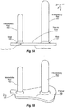
- Figure 1A depicts an example of dual stem implant 100.
- Dual stem implant 100 includes intramedullary rod 101, intramedullary rod 102, and base plate 103.
- Base plate 103 can be constructed of a smooth, mechanically tough material, such as, for example, ultra high molecular weight polyethylene (“UHMWPE”), stainless steel, titanium based alloy, or cobalt-chrome based alloy.
- Base plate 103 can be shaped in a pressure-reducing configuration, such as, for example, a moderately flattened domed shape.
- the moderately flattened dome can be backed with a reinforcing metal substrate.
- the metal substrate can be of a solid, non-porous configuration.
- base plate 103 is a tough, dome-shaped, pressure reducing surface backed with a reinforcing metal shell that is further backed with a porous, bone infiltratable material.
- the shape of the base plate 103 can be anatomically matched to the cross section (or remaining area) of the tibia and fibula at the particular level of amputation.
- the base plate 103 can be of a size somewhat larger than the cross section of the associated bones, so as to provide a greater area of load bearing for the distal soft tissues during ambulation.
- base plate 103 includes a proximal side 134 (facing towards amputated bones) and distal side 136 (facing away from amputated bones). Extending out from proximal side 134 are intramedullary rods 101 and 102. Intramedullary rods 101 and 102 are mechanically connected to the proximal side of base plate 103. Intramedullary rods 101 and 102 can be mechanically connected to base plate 103 using any of a variety of techniques, such as, for example, welding, screw threads, adhesives, etc. As depicted in Figure 1A , welds 127 and 128 mechanically connect intramedullary rods 101 and 102 respectively to base plate 103. Intramedullary rods 101 and 102 may or may not be substantially parallel to one another depending on the type and level of amputation.
- Intramedullary rod 101 is configured for insertion into the distal end of an amputated tibia.
- the diameter of intramedullary rod 101 can be matched to a corresponding intramedullary bone canal of the amputated tibia.
- Intramedullary rod 102 is configured for insertion into the distal end of an amputated fibula.
- the diameter of intramedullary rod 102 can be matched to a corresponding intramedullary bone canal of the amputated fibula.
- the surface of the intramedullary rods 101 and 102 may be smooth or textured so as to permit the ingrowth of bone.
- the surfaces include porous textured (e.g., metallic) materials.
- the ends of intramedullary rods 101 and 102 can be bluntly rounded so as to facilitate safe egress into corresponds intramedullary bone canals.
- the cross-sectional profile of the intramedullary rods 101 and 102 can be circular. Alternately, intramedullary rods 101 and 102 can be of a shape with a higher aspect ratio to aid in mechanical anti-rotation control.
- Figure 1B depicts a perspective view of dual stem implant 100. As depicted, intramedullary rods 101 and 102 extend out of proximal side 134 of base plate 103.
- the length of intramedullary rod 101 and intramedullary rod 102 can be configured to maximize their insertion into the intramedullary bone canals of an amputated tibia and fibula.
- the position of intramedullary rod 101 and intramedullary rod 102 can also be configured to maximize their insertion into the intramedullary bone canals of the amputated tibia and fibula.
- the position of intramedullary rod 101 relative to intramedullary 102 can be used to maintain appropriate separation between the remaining portion of an amputated tibia and the remaining portion of an amputated fibula after insertion.
- Figure 1C depicts a top view of dual stem implant 100. As depicted, positions 111 and 112 indicate the location for mechanical connections between intramedullary rods 101 and 102 respectively and base plate 103. Positions 111 and 112 can be varied to provide increased patient benefit based on the level and type of amputation.
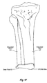
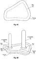
- Figure ID depicts a distal view of intramedullary bone canals in an amputated tibia 121 and amputated fibula 122 respectively.
- amputated tibia 121 and fibula 122 include intramedullary bone canals 123 and 124 respectively.
- Intramedullary bone canals can be formed in the amputated tibia 121 and amputated fibula 122 using a surgical reaming tool.
- intramedullary rods 101 and 102 are inserted into intramedullary bone canals.
- Figure 1E depicts a view of dual stem implant 100 relative to amputated tibia 121 and amputated fibula 122.
- intramedullary rods 101 and 102 can be inserted into intramedullary bone canals 123 and 124 respectively.
- Attachment of intramedullary rods 101 and 102 to amputated tibia 121 and amputated fibula 122 respectively can result in a (e.g., relatively intimate) fit between a porous textured (e.g., metallic) rod surface and corresponding intramedullary bone canal.
- the attachment can facilitate bone growth into the porous textured surface.
- an intentional gap can be formed between an intramedullary rod and corresponding intramedullary bone canal.
- the canal can provide adequate space for the mechanical bonding of an intermediate layer of bone cement.
- Typical bone cements used for orthopedic implant fixation such as, for example, those based upon PMMA chemistries, can be used.
- Insertion of higher aspect ratio intramedullary rods can include a multi-step reaming system configured to yield the desired stem cross-section shape.
- dual stem implant 100 into amputated bone ends is complete when the inner surface of the base plate 103 securely contacts the amputated surface of the amputated tibia and fibula.
- Dual intramedullary rods e.g., 101 and 102 are stabilized to the bone shafts via press fit mechanisms or cementation. Alternatively, rod fixation is through insertion of bicortical distal locking screws.
- Figure 1F depicts a view of the dual stem implant 100 inserted into the amputated tibia 121 and amputated fibula 122.
- Appropriate insertion of dual stem implant 100 and fixation of intramedullary rods 101 and 102 significantly decreases any independent movement of amputated tibia 121 and amputated fibula 122 relative to one another. Reducing independent movement of amputated tibia 121 and amputated fibula 122 can result in a corresponding decrease in patient pain levels.
- intramedullary rods can be mechanically connected to a base plate using any of a variety of mechanisms.
- a dual stem implant can be configured (and pre-designed for a specific patient) as a single piece wherein the base plate and rods securely attached to each other via casting or welding manufacturing operations.
- the base plate and intramedullary rods may be presented as separate entities. Accordingly, a surgical team is given additional clinical flexibility to select from various base plate dimensions, stem lengths, stem diameters and base plate surface preparations and stem surface preparations to optimally match the clinical situation.
- FIG. 2A depicts threaded intramedullary rods 201 and 202 relative to threaded base plate 203.
- base plate 203 includes receiving holes 272 and 273.
- Receiving hole 272 includes threading 228 that is configured to match threading 252 of intramedullary rod 202.
- receiving hole 273 includes threading 227 that is configured to match threading 251 of intramedullary rod 201.
- intramedullary rod 201 can be screwed into receiving hole 273 to mechanically connect intramedullary rod 201 to base plate 203.
- intramedullary rod 202 can be screwed into receiving hole 272 to mechanically connect intramedullary rod 202 to base plate 203.
- Figure 2B depicts intramedullary rods 201 and 202 screwed into receiving holes 273 and 272 respectively of base plate 203 to form dual stem implant 200.
- Deformable inserts can be used to minimize unwanted backing out of threaded components. Additional, contrasting threading directions (a right-handed tibial stem and a left-handed fibular stem) can be utilized to further inhibit unwanted component backing out.
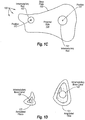
- FIG. 3A depicts an example of an anatomic base plate 301.
- Anatomic base plate 301 is configured to extend to, or essentially anatomically match up with, the edges of the distal end of an amputated tibia and fibula (e.g., as depicted in Figure 1F ).
- FIG. 3B depicts an example of a walker base plate 302.
- Walker base plate 302 is configured to extend significantly past the edges of the distal end of an amputated tibia and fibula in one or more locations.
- Walker base plate 302 provides increased lateral surface area in the front portion to better distribute concentrated loads, such as, for example, experienced during toe off phase ambulation.
- Walker base plate 302 can provide significant more bearing surface (e.g., approximately a 50% increase) than anatomic base plate 301.
- an end cap of softer material is affixed to the distal side of a base plate prior to or subsequent to insertion of a dual stem implant into amputated bone ends.
- Figure 4A depicts an example of end cap 107.
- End cap 107 can be made of a plastic or other polymer composition.
- End cap 107 provides a mechanism to further distribute concentrated loads.
- End cap 107 can be designed for use with any configuration of base plate. Accordingly, end cap 107 can be configured for use with anatomical base plates as well as walker base plates.
- Figure 4B depicts end cap 107 affixed to the distal side of dual steam implant 100.
- Figure 4C illustrates dual stem implant 100, with end cap 107 affixed, inserted into amputated tibia 121 and amputated fibula 122.
- End cap 107 can be affixed to base plate 103 using adhesives or other attachment mechanisms.
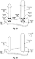
- an amputation stabilization device includes one or more hollow tubes.
- a hollow tube can used in a stemmed implant to replace an intramedullary rod.
- Figure 5A depicts stemmed implant 500 including intramedullary rod 501 and hollow tube 502.
- Hollow tube 502 can be constructed using any material and/or construction technique used to construct an intramedullary rod.
- Hollow tube 502 can be mechanically connected to base plate 503 using any of the mechanisms for mechanically connecting an intramedullary rod to base plate 503.
- Stemmed implant 500 can be used, for example, when the cross-sectional area of an amputated bone (e.g., an amputated fibula) does not provide sufficient size for stable intramedullary fixation.
- Intramedullary rod 501 and hollow tube 502 may or may not be substantially parallel to one another depending on the type and level of amputation.
- hollow tube 502 has a circular cross section.
- the diameter of hollow tube 502 can be selected to be slightly larger than the maximum diameter of an amputated bone for a give amputation level.
- Figure 5B depicts stemmed implant 500, including hollow tube 502, relative to amputated tibia 121 and amputated fibula 122.
- hollow tube 502 is of sufficient size to fit over the outside of amputated fibula 122 during insertion of intramedullary rod 501 into intramedullary bone canal 123.
- Figure 5C depicts stemmed implant 500 attached to the amputated tibia 121 and amputated fibula 122.
- Mechanical retention of a remaining portion of an amputated bone (e.g., amputated fibula 122) within hollow tube 502 can be facilitated using orthopedic attachment techniques including, for example, orthopedic bone cements and screws.
- An end cap, such as, for example, end cap 107 can also be attached to stemmed implants including hollow tubes.
- an amputation stabilization device includes two hollow tubes.
- the hollow tubes may or may not be substantially parallel to one another depending on the type and level of amputation.
- Embodiments of the invention also include amputation stabilization devices for the radius and ulna of an amputated forearm.
- amputation stabilization devices for the radius and ulna of an amputated forearm.
- These embodiments can be dual stemmed devices, stemmed implants including a hollow tube, or amputation stabilization devices including two hollow tubes.
- End caps such as, for example, end cap 107 can also be used with these embodiments when appropriate.
- first and second intramedullary rods, an intramedullary rod and a hollow tube, or fist and second hollow tubes can be configured relative to and positioned on a base plate to provide for proper biomechanics when the user rotates their wrist and/or forearm.
- Amputation stabilization devices configured in accordance with the principals of the of the present invention can be supported by a host of devices used in the field of orthopedic implant surgery, such as, for example, within the subspecialty of total joint arthroplasty.
- Devices can include cutting guides, reaming guides, combination cutting/reaming guides, intramedullary reamers, sterile bone cements, bone cement mixing equipment and bone cement extruding equipment.
- embodiments of invention reduce the occurrence of soft tissue/bone end adhesions by covering the interface between the two types of tissues with a biologically inert material.
- Embodiments of the invention also reduce the occurrence of "chop sticking" through prevention of independent bone movement.
Landscapes
- Health & Medical Sciences (AREA)
- Orthopedic Medicine & Surgery (AREA)
- Life Sciences & Earth Sciences (AREA)
- Surgery (AREA)
- Animal Behavior & Ethology (AREA)
- Veterinary Medicine (AREA)
- Public Health (AREA)
- Engineering & Computer Science (AREA)
- Biomedical Technology (AREA)
- Heart & Thoracic Surgery (AREA)
- General Health & Medical Sciences (AREA)
- Molecular Biology (AREA)
- Medical Informatics (AREA)
- Nuclear Medicine, Radiotherapy & Molecular Imaging (AREA)
- Neurology (AREA)
- Cardiology (AREA)
- Oral & Maxillofacial Surgery (AREA)
- Transplantation (AREA)
- Vascular Medicine (AREA)
- Prostheses (AREA)
- Surgical Instruments (AREA)
Claims (16)
- Amputationsstabilisierungsvorrichtung zum mechanischen Stabilisieren eines ersten Knochens relativ zu einem zweiten unterschiedlichen Knochen innerhalb einer amputierten menschlichen Extremität, wobei das Amputationsimplantat umfasst:eine erste stabilisierende Komponente, die für die Verbindung mit dem distalen Ende des ersten Knochens konfiguriert ist;eine zweite stabilisierende Komponente, die für die Verbindung mit dem distalen Ende des zweiten Knochens konfiguriert ist;eine Basisplatte, die eine proximale Seite und eine distale Seite hat, wobei die Basisplatte mechanisch mit der ersten stabilisierenden Komponente verbunden ist und die Basisplatte mechanisch mit der zweiten stabilisierenden Komponente verbunden ist;wobei sich die erste stabilisierende Komponente aus der proximalen Seite der Basisplatte heraus erstreckt;wobei sich die zweite stabilisierende Komponente aus der proximalen Seite der Basisplatte heraus erstreckt;wobei die Position der ersten stabilisierenden Komponente an der Basisplatte relativ zu der Position der zweiten stabilisierenden Komponente an der Basisplatte so konfiguriert ist,dass eine geeignete Trennung zwischen dem ersten Knochen unddem zweiten Knochen aufrechterhalten wird, wenn die erste stabilisierende Komponente und die zweite stabilisierende Komponente mit dem ersten Knochen bzw. dem zweiten Knochen verbunden werden, und dass unabhängige Bewegung des ersten Knochens und des zweiten Knochens innerhalb der amputierten menschlichen Extremität verringert wird; undwobei die Basisplatte eine Form hat, die sich einem noch vorhandenen Querschnitt der amputierten Tibia und Fibula annähert,dadurch gekennzeichnet, dassdie Form der Basisplatte ungleichmäßig, nicht symmetrisch ist.
- Amputationsstabilisierungsvorrichtung gemäß Anspruch 1, wobei mindestens eine der ersten stabilisierenden Komponente oder der zweiten stabilisierenden Komponente einen intramedullären Stab, der für das Einführen in einen intramedullären Knochenkanal konfiguriert ist, umfasst, und
wobei der intramedulläre Stab für das Einführen in einen intramedullären Knochenkanal in einem distalen Ende einer Tibia eines amputierten menschlichen Beins konfiguriert ist. - Amputationsstabilisierungsvorrichtung gemäß Anspruch 1 oder 2, wobei mindestens eine der ersten stabilisierenden Komponente oder der zweiten stabilisierenden Komponente einen intramedullären Stab, der für das Einführen in einen intramedullären Knochenkanal konfiguriert ist, umfasst und
wobei eine der ersten oder zweiten stabilisierenden Komponenten ein hohles Rohr, das so konfiguriert ist, dass es äußerlich einen Teil eines Knochens einer amputierten Extremität bedeckt, umfasst. - Amputationsstabilisierungsvorrichtung gemäß Anspruch 1 oder 2, wobei die Amputationsstabilisierungsvorrichtung eine Doppelschaftvorrichtung ist, und wobei:die erste stabilisierende Komponente einen ersten intramedullären Stab, der für das Einführen in ein distales Ende des ersten Knochens konfiguriert ist, umfasst, wobei die Größe des ersten intramedullären Stabes auf der Querschnittsfläche des ersten Knochens basiert, wobei die Länge des ersten intramedullären Stabes auf der Länge des noch vorhandenen Teils des ersten Knochens basiert;die zweite stabilisierende Komponente einen zweiten intramedullären Stab, der für das Einführen in ein distales Ende des zweiten Knochens konfiguriert ist, umfasst, wobei die Größe des zweiten intramedullären Stabes auf der Querschnittsfläche des zweiten Knochens basiert, wobei die Länge des zweiten intramedullären Stabes auf der Länge des noch vorhandenen Teils des zweiten Knochens basiert.
- Amputationsstabilisierungsvorrichtung gemäß Anspruch 4, wobei:der erste intramedulläre Stab für das Einführen in einen intramedullären Knochenkanal in einem distalen Ende eines Radius eines amputierten menschlichen Arms konfiguriert ist;der zweite intramedulläre Stab für das Einführen in einen intramedullären Knochenkanal in einem distalen Ende einer Ulna eines amputierten menschlichen Arms konfiguriert ist; undder erste intramedulläre Stab so an der Basisplatte befestigt ist, dass eine Rotation des Radius und der Ulna ermöglicht wird, um eine geeignete Biomechanik bereitzustellen, wenn ein Nutzer sein Handgelenk oder seinen Unterarm rotiert.
- Amputationsstabilisierungsvorrichtung gemäß Anspruch 4, wobei:der erste intramedulläre Stab für das Einführen in einen intramedullären Knochenkanal in einem distalen Ende einer Tibia eines amputierten menschlichen Beins konfiguriert ist; undder zweite intramedulläre Stab für das Einführen in einen intramedullären Knochenkanal in einem distalen Ende einer Fibula eines amputierten menschlichen Beins konfiguriert ist.
- Amputationsstabilisierungsvorrichtung gemäß Anspruch 6, wobei der erste intramedulläre Stab einen Durchmesser hat, der geringer ist als ein Durchmesser eines ersten intramedullären Kanals, der in einer amputierten Tibia ausgebohrt wurde, um Platz für das Einbringen von Knochenzement in den ersten intramedullären Kanal zu ermöglichen, und wobei der zweite intramedulläre Stab einen intramedullären Stab umfasst, der einen Durchmesser hat, der geringer ist als ein Durchmesser eines zweiten intramedullären Kanals, der in einer amputierten Fibula ausgebohrt wurde, um Platz für das Einbringen von Knochenzement in den zweiten intramedullären Kanal zu ermöglichen.
- Amputationsstabilisierungsvorrichtung gemäß einem der Ansprüche 4 bis 7, wobei mindestens einer der ersten oder zweiten intramedullären Stäbe eine kreisförmige Querschnittsfläche hat.
- Amputationsstabilisierungsvorrichtung gemäß einem der Ansprüche 1 bis 8, die weiterhin eine Polymerendkappe, die mechanisch an dem distalen Ende der Basisplatte befestigt ist, umfasst, wobei die Polymerendkappe so konfiguriert ist, dass sie die distale Seite der Basisplatte vollständig bedeckt, wobei die Polymerendkappe einen Mechanismus zur weiteren Gewichtsverteilung bereitstellt.
- Amputationsstabilisierungsvorrichtung gemäß einem der Ansprüche 1 bis 4, 6 und 7, wobei die Fläche der Basisplatte so konfiguriert ist, dass sie anatomisch zu einer Fläche eines distalen Endes eines amputierten Beins passt.
- Amputationsstabilisierungsvorrichtung gemäß einem der Ansprüche 1 bis 4, 6 und 7, wobei die ungleichmäßige, nicht symmetrische Form der Basisplatte so konfiguriert ist, dass sie sich über Kanten des ersten Knochens und des zweiten Knochens hinaus erstreckt, wenn sie an einem distalen Ende eines amputierten Beins befestigt ist, um eine erhöhte laterale Oberfläche bereitzustellen, um so konzentrierte Belastungen, die während dem Gehen oder Rennen erfahren werden, besser zu verteilen.
- Amputationsstabilisierungsvorrichtung gemäß einem der Ansprüche 1 bis 11, wobei die mechanische Verbindung zwischen den ersten und zweiten stabilisierenden Komponenten und der Basisplatte eine Schweißverbindung umfasst.
- Amputationsstabilisierungsvorrichtung gemäß einem der Ansprüche 1 bis 11, wobei die mechanische Verbindung zwischen den ersten und zweiten stabilisierenden Komponenten und der Basisplatte Schraubgewinde umfasst.
- Amputationsstabilisierungsvorrichtung gemäß Anspruch 13, wobei die Schraubgewinde für die erste stabilisierende Komponente in einer ersten Richtung gewunden sind und die Schraubgewinde für die zweite stabilisierende Komponente in einer zweiten entgegengesetzten Richtung gewunden sind, um ein Ausbrechen der ersten und zweiten stabilisierenden Komponente im Anschluss an die Befestigung an einer amputierten Extremität zu verhindern.
- Amputationsstabilisierungsvorrichtung gemäß einem der Ansprüche 1 bis 14, wobei die proximale Seite der Basisplatte eine Oberfläche enthält, die so konfiguriert ist, dass sie Knochenwachstum in die Basisplatte ermöglicht.
- Amputationsstabilisierungsvorrichtung gemäß einem der Ansprüche 1, 2 und 4 bis 15, wobei mindestens eine der ersten stabilisierenden Komponente oder der zweiten stabilisierenden Komponente ein hohles Rohr enthält, das so konfiguriert ist, dass es einen Teil eines noch vorhandenen Endes des ersten Knochens oder des zweiten Knochens äußerlich bedeckt.
Applications Claiming Priority (2)
| Application Number | Priority Date | Filing Date | Title |
|---|---|---|---|
| US12/238,108 US7972384B2 (en) | 2008-02-05 | 2008-09-25 | Amputation stabilization device |
| PCT/US2009/058314 WO2010036855A2 (en) | 2008-09-25 | 2009-09-25 | Amputation stabilization device |
Publications (3)
| Publication Number | Publication Date |
|---|---|
| EP2337520A2 EP2337520A2 (de) | 2011-06-29 |
| EP2337520A4 EP2337520A4 (de) | 2014-03-12 |
| EP2337520B1 true EP2337520B1 (de) | 2018-05-16 |
Family
ID=40932456
Family Applications (1)
| Application Number | Title | Priority Date | Filing Date |
|---|---|---|---|
| EP09816885.9A Not-in-force EP2337520B1 (de) | 2008-09-25 | 2009-09-25 | Vorrichtung zur stabilisierung von amputationen |
Country Status (4)
| Country | Link |
|---|---|
| US (1) | US7972384B2 (de) |
| EP (1) | EP2337520B1 (de) |
| JP (1) | JP5486004B2 (de) |
| WO (1) | WO2010036855A2 (de) |
Families Citing this family (12)
| Publication number | Priority date | Publication date | Assignee | Title |
|---|---|---|---|---|
| US20110118839A1 (en) * | 2009-11-13 | 2011-05-19 | Robert Nutter | Bone plug |
| RU2475213C2 (ru) * | 2010-12-13 | 2013-02-20 | Игорь Владимирович Карпич | Эндопротез культи трубчатой кости |
| RU2483696C2 (ru) * | 2011-03-30 | 2013-06-10 | Валерий Сергеевич Матюшин | Проленовый сетчатый имплант для формирования культи нижней конечности без натяжения при ампутации на уровне голени и бедра |
| US8882851B2 (en) * | 2011-09-20 | 2014-11-11 | Larry Nelson Smith | Implantable prosthetic device for distribution of weight on amputated limb and method of use with an external prosthetic device |
| US8932367B2 (en) | 2013-02-13 | 2015-01-13 | Larry N. Smith | Shock absorbing implantable limb prosthetic |
| US10238436B2 (en) * | 2014-05-16 | 2019-03-26 | University Of Kentucky Research Foundation | Temporary fracture stabilization device |
| TW201707653A (zh) * | 2015-08-18 | 2017-03-01 | Pao Nan Biotech Co Ltd | 腓骨截斷處之防止骨融合銜接裝置 |
| CN105496531B (zh) * | 2016-02-04 | 2017-11-28 | 宝楠生技股份有限公司 | 腓骨截断后再固定于胫骨的固定装置 |
| US11246634B2 (en) | 2017-05-02 | 2022-02-15 | Orthopediatrics Corp. | End cap for intramedullary nail |
| CN107928843B (zh) * | 2017-11-10 | 2023-07-28 | 北京爱康宜诚医疗器材有限公司 | 胫骨平台假体组件及具有其的膝关节假体组件 |
| CN108042244B (zh) * | 2017-11-10 | 2023-07-28 | 北京爱康宜诚医疗器材有限公司 | 胫骨填充块假体及具有其的膝关节假体组件 |
| US11317090B2 (en) | 2019-08-12 | 2022-04-26 | Tencent America LLC | Method and apparatus for video coding |
Family Cites Families (29)
| Publication number | Priority date | Publication date | Assignee | Title |
|---|---|---|---|---|
| US4547912A (en) | 1983-09-01 | 1985-10-22 | Sherva Parker Carole J | Amputation apparatus |
| IL71638A (en) | 1984-04-25 | 1984-10-31 | Eliahu Antebi | Weight distributing prosthesis attached to the bone for below and above the knee amputations |
| DE3439993C2 (de) | 1984-11-02 | 1986-12-04 | Friedrichsfeld GmbH Keramik- und Kunststoffwerke, 6800 Mannheim | Implantat zur Versorgung von Amputationsstümpfen |
| JPH03501459A (ja) * | 1988-09-21 | 1991-04-04 | クラスノダルスキ クラエヴォイ ソヴェト ウセソユズノゴ オブチェストヴァ イゾブレタテレイ イ ラツィオナリザトロフ | 人の義肢の取付け装置 |
| US4995883A (en) * | 1989-02-08 | 1991-02-26 | Smith & Nephew Richards Inc. | Modular hip prosthesis |
| WO1991003994A1 (fr) * | 1989-09-21 | 1991-04-04 | Krasnodarsky Kraevoi Sovet Vsesojuznogo Obschestva Izobretatelei I Ratsionalizatorov | Dispositif de fixation d'une prothese destinee a une extremite |
| SE9001521D0 (sv) * | 1990-04-26 | 1990-04-26 | Per Ingvar Branemark | System och metod foer rekonstruktion av leder, i synnerhet handleder |
| US5314499A (en) * | 1991-04-04 | 1994-05-24 | Collier Jr Milo S | Artificial limb including a shin, ankle and foot |
| US5326365A (en) | 1992-04-10 | 1994-07-05 | Alvine Franklin G | Ankle implant |
| US7141073B2 (en) | 1993-11-01 | 2006-11-28 | Biomet, Inc. | Compliant fixation of external prosthesis |
| DE4338746C2 (de) * | 1993-11-12 | 1996-07-04 | Otmar Dr Behr | Amputationsstumpf-Endoprothese |
| FR2778088B1 (fr) * | 1998-04-30 | 2000-09-08 | Materiel Orthopedique En Abreg | Implant anterieur notamment pour le rachis cervical |
| US6238434B1 (en) | 1998-08-05 | 2001-05-29 | Biomedical Engineering Trust I | Knee joint prosthesis with spinout prevention |
| DE19857907C1 (de) | 1998-12-16 | 2000-04-13 | Eska Implants Gmbh & Co | Oberschenkelstumpf-Endoprothese für eine exoprothetische Versorgung |
| US7963966B2 (en) * | 2000-06-06 | 2011-06-21 | Cole J Dean | Bone fixation system and method of use |
| US6709459B1 (en) | 2000-08-31 | 2004-03-23 | Mayo Foundation For Medical Education And Research | Radial implant system |
| US20030055507A1 (en) * | 2001-09-11 | 2003-03-20 | Incumed, Incorporated | Modular prosthesis and insertion tool for bone structures |
| NO315635B1 (no) | 2002-01-18 | 2003-10-06 | Cypromed As | Protesesett |
| FR2835425B1 (fr) * | 2002-02-04 | 2004-04-09 | Tornier Sa | Element prothetique comprenant deux composants et procede d'assemblage d'un tel element prothetique |
| US6923832B1 (en) | 2002-03-21 | 2005-08-02 | Trigon Incorporated | Revision tibial component |
| US7534270B2 (en) | 2003-09-03 | 2009-05-19 | Integra Lifesciences Corporation | Modular total ankle prosthesis apparatuses and methods |
| US7524323B2 (en) | 2004-04-16 | 2009-04-28 | Kyphon Sarl | Subcutaneous support |
| US20060015188A1 (en) | 2004-07-17 | 2006-01-19 | Nexus Consulting Limited | Prosthesis and method of implantation |
| US20070038302A1 (en) * | 2005-08-15 | 2007-02-15 | Biomet Manufacturing Corp. | Method and apparatus for the preparation of an inlaid glenoid |
| US20070142917A1 (en) * | 2005-10-26 | 2007-06-21 | Roche Christopher P | Apparatus and method to obtain bone fixation |
| US7374577B2 (en) | 2005-12-22 | 2008-05-20 | Workers Accident Medical Corporation | Implant device for osseointegration to endure weight |
| US20070162150A1 (en) | 2006-01-12 | 2007-07-12 | Fago John R | Modular prosthetic implant for upper and lower extremity amputees |
| US20070233103A1 (en) * | 2006-03-31 | 2007-10-04 | Metzinger Anthony J | Intramedullary nail, intramedullary nail assembly and method |
| US20080015691A1 (en) * | 2006-06-15 | 2008-01-17 | Depuy Products, Inc. | Orthopaedic implants having bioresorbable posts |
-
2008
- 2008-09-25 US US12/238,108 patent/US7972384B2/en not_active Expired - Fee Related
-
2009
- 2009-09-25 EP EP09816885.9A patent/EP2337520B1/de not_active Not-in-force
- 2009-09-25 WO PCT/US2009/058314 patent/WO2010036855A2/en not_active Ceased
- 2009-09-25 JP JP2011529241A patent/JP5486004B2/ja not_active Expired - Fee Related
Non-Patent Citations (1)
| Title |
|---|
| None * |
Also Published As
| Publication number | Publication date |
|---|---|
| WO2010036855A2 (en) | 2010-04-01 |
| US20090198342A1 (en) | 2009-08-06 |
| JP2012503532A (ja) | 2012-02-09 |
| WO2010036855A3 (en) | 2010-05-20 |
| US7972384B2 (en) | 2011-07-05 |
| EP2337520A4 (de) | 2014-03-12 |
| JP5486004B2 (ja) | 2014-05-07 |
| EP2337520A2 (de) | 2011-06-29 |
Similar Documents
| Publication | Publication Date | Title |
|---|---|---|
| EP2337520B1 (de) | Vorrichtung zur stabilisierung von amputationen | |
| Haentjens et al. | Proximal femoral replacement prosthesis for salvage of failed hip arthroplasty: complications in a 2–11 year follow-up study in 19 elderly patients | |
| US8858646B2 (en) | Hip stem prosthesis | |
| US20120245701A1 (en) | Hemi Ankle Implant | |
| JP6469589B2 (ja) | 下肢切断のためのインプラント | |
| GB2094629A (en) | Artificial hip, knee and femur | |
| JP2013523319A (ja) | 大腿ベース部および脛骨ベース部 | |
| Ess et al. | Non-constrained titanium-polyethylene total endoprosthesis in the treatment of hallux rigidus: a prospective clinical 2-year follow-up study | |
| EP3210576B1 (de) | Hüftgelenkvorrichtung | |
| WO2015157809A1 (en) | An osseointegrable device | |
| EP2451400B1 (de) | Hüftgelenkvorrichtung | |
| US20250366890A1 (en) | Stemless Semi-Constrained Implantable Joint Replacement Device | |
| JP2004130113A (ja) | セメント接合式プロテーゼキット | |
| US20250213367A1 (en) | Stemless Semi-Constrained Implantable Joint Replacement Device | |
| Gill | Principles of joint arthroplasty as applied to the ankle | |
| US10595915B2 (en) | Bone implant devices, instruments and methods of use | |
| CN103705319A (zh) | 生物固定型胫骨平台 | |
| CN113367846B (zh) | 一种胫骨假体 | |
| Ritterman et al. | Management of the'young'patient with hip disease | |
| RU2385693C1 (ru) | Ножка эндопротеза тазобедренного сустава | |
| US20220323228A1 (en) | Hip Joint Device and Method | |
| JP2011139785A (ja) | ネイル挿入型人工膝関節 | |
| JP2024518851A (ja) | プロテーゼ部品および/または生体インプラントの設置用キット | |
| Heald et al. | Press-Fit Osseointegration for the Forearm Amputee | |
| WO2025114986A1 (en) | Intercalated and osseointegrated prosthesis for finger and thumb amputation |
Legal Events
| Date | Code | Title | Description |
|---|---|---|---|
| PUAI | Public reference made under article 153(3) epc to a published international application that has entered the european phase |
Free format text: ORIGINAL CODE: 0009012 |
|
| 17P | Request for examination filed |
Effective date: 20110404 |
|
| AK | Designated contracting states |
Kind code of ref document: A2 Designated state(s): AT BE BG CH CY CZ DE DK EE ES FI FR GB GR HR HU IE IS IT LI LT LU LV MC MK MT NL NO PL PT RO SE SI SK SM TR |
|
| AX | Request for extension of the european patent |
Extension state: AL BA RS |
|
| DAX | Request for extension of the european patent (deleted) | ||
| A4 | Supplementary search report drawn up and despatched |
Effective date: 20140211 |
|
| RIC1 | Information provided on ipc code assigned before grant |
Ipc: A61F 2/00 20060101AFI20140205BHEP |
|
| 17Q | First examination report despatched |
Effective date: 20160115 |
|
| GRAJ | Information related to disapproval of communication of intention to grant by the applicant or resumption of examination proceedings by the epo deleted |
Free format text: ORIGINAL CODE: EPIDOSDIGR1 |
|
| GRAP | Despatch of communication of intention to grant a patent |
Free format text: ORIGINAL CODE: EPIDOSNIGR1 |
|
| INTG | Intention to grant announced |
Effective date: 20171129 |
|
| GRAS | Grant fee paid |
Free format text: ORIGINAL CODE: EPIDOSNIGR3 |
|
| GRAA | (expected) grant |
Free format text: ORIGINAL CODE: 0009210 |
|
| AK | Designated contracting states |
Kind code of ref document: B1 Designated state(s): AT BE BG CH CY CZ DE DK EE ES FI FR GB GR HR HU IE IS IT LI LT LU LV MC MK MT NL NO PL PT RO SE SI SK SM TR |
|
| REG | Reference to a national code |
Ref country code: GB Ref legal event code: FG4D |
|
| REG | Reference to a national code |
Ref country code: CH Ref legal event code: EP |
|
| REG | Reference to a national code |
Ref country code: IE Ref legal event code: FG4D |
|
| REG | Reference to a national code |
Ref country code: DE Ref legal event code: R096 Ref document number: 602009052360 Country of ref document: DE |
|
| REG | Reference to a national code |
Ref country code: AT Ref legal event code: REF Ref document number: 998867 Country of ref document: AT Kind code of ref document: T Effective date: 20180615 |
|
| REG | Reference to a national code |
Ref country code: FR Ref legal event code: PLFP Year of fee payment: 10 |
|
| REG | Reference to a national code |
Ref country code: NL Ref legal event code: MP Effective date: 20180516 |
|
| REG | Reference to a national code |
Ref country code: LT Ref legal event code: MG4D |
|
| PG25 | Lapsed in a contracting state [announced via postgrant information from national office to epo] |
Ref country code: BG Free format text: LAPSE BECAUSE OF FAILURE TO SUBMIT A TRANSLATION OF THE DESCRIPTION OR TO PAY THE FEE WITHIN THE PRESCRIBED TIME-LIMIT Effective date: 20180816 Ref country code: FI Free format text: LAPSE BECAUSE OF FAILURE TO SUBMIT A TRANSLATION OF THE DESCRIPTION OR TO PAY THE FEE WITHIN THE PRESCRIBED TIME-LIMIT Effective date: 20180516 Ref country code: SE Free format text: LAPSE BECAUSE OF FAILURE TO SUBMIT A TRANSLATION OF THE DESCRIPTION OR TO PAY THE FEE WITHIN THE PRESCRIBED TIME-LIMIT Effective date: 20180516 Ref country code: ES Free format text: LAPSE BECAUSE OF FAILURE TO SUBMIT A TRANSLATION OF THE DESCRIPTION OR TO PAY THE FEE WITHIN THE PRESCRIBED TIME-LIMIT Effective date: 20180516 Ref country code: LT Free format text: LAPSE BECAUSE OF FAILURE TO SUBMIT A TRANSLATION OF THE DESCRIPTION OR TO PAY THE FEE WITHIN THE PRESCRIBED TIME-LIMIT Effective date: 20180516 Ref country code: NO Free format text: LAPSE BECAUSE OF FAILURE TO SUBMIT A TRANSLATION OF THE DESCRIPTION OR TO PAY THE FEE WITHIN THE PRESCRIBED TIME-LIMIT Effective date: 20180816 |
|
| PGFP | Annual fee paid to national office [announced via postgrant information from national office to epo] |
Ref country code: DE Payment date: 20180911 Year of fee payment: 10 Ref country code: FR Payment date: 20180813 Year of fee payment: 10 |
|
| PG25 | Lapsed in a contracting state [announced via postgrant information from national office to epo] |
Ref country code: NL Free format text: LAPSE BECAUSE OF FAILURE TO SUBMIT A TRANSLATION OF THE DESCRIPTION OR TO PAY THE FEE WITHIN THE PRESCRIBED TIME-LIMIT Effective date: 20180516 Ref country code: LV Free format text: LAPSE BECAUSE OF FAILURE TO SUBMIT A TRANSLATION OF THE DESCRIPTION OR TO PAY THE FEE WITHIN THE PRESCRIBED TIME-LIMIT Effective date: 20180516 Ref country code: HR Free format text: LAPSE BECAUSE OF FAILURE TO SUBMIT A TRANSLATION OF THE DESCRIPTION OR TO PAY THE FEE WITHIN THE PRESCRIBED TIME-LIMIT Effective date: 20180516 Ref country code: GR Free format text: LAPSE BECAUSE OF FAILURE TO SUBMIT A TRANSLATION OF THE DESCRIPTION OR TO PAY THE FEE WITHIN THE PRESCRIBED TIME-LIMIT Effective date: 20180817 |
|
| PGFP | Annual fee paid to national office [announced via postgrant information from national office to epo] |
Ref country code: GB Payment date: 20180919 Year of fee payment: 10 |
|
| REG | Reference to a national code |
Ref country code: AT Ref legal event code: MK05 Ref document number: 998867 Country of ref document: AT Kind code of ref document: T Effective date: 20180516 |
|
| PG25 | Lapsed in a contracting state [announced via postgrant information from national office to epo] |
Ref country code: EE Free format text: LAPSE BECAUSE OF FAILURE TO SUBMIT A TRANSLATION OF THE DESCRIPTION OR TO PAY THE FEE WITHIN THE PRESCRIBED TIME-LIMIT Effective date: 20180516 Ref country code: PL Free format text: LAPSE BECAUSE OF FAILURE TO SUBMIT A TRANSLATION OF THE DESCRIPTION OR TO PAY THE FEE WITHIN THE PRESCRIBED TIME-LIMIT Effective date: 20180516 Ref country code: SK Free format text: LAPSE BECAUSE OF FAILURE TO SUBMIT A TRANSLATION OF THE DESCRIPTION OR TO PAY THE FEE WITHIN THE PRESCRIBED TIME-LIMIT Effective date: 20180516 Ref country code: CZ Free format text: LAPSE BECAUSE OF FAILURE TO SUBMIT A TRANSLATION OF THE DESCRIPTION OR TO PAY THE FEE WITHIN THE PRESCRIBED TIME-LIMIT Effective date: 20180516 Ref country code: RO Free format text: LAPSE BECAUSE OF FAILURE TO SUBMIT A TRANSLATION OF THE DESCRIPTION OR TO PAY THE FEE WITHIN THE PRESCRIBED TIME-LIMIT Effective date: 20180516 Ref country code: AT Free format text: LAPSE BECAUSE OF FAILURE TO SUBMIT A TRANSLATION OF THE DESCRIPTION OR TO PAY THE FEE WITHIN THE PRESCRIBED TIME-LIMIT Effective date: 20180516 Ref country code: DK Free format text: LAPSE BECAUSE OF FAILURE TO SUBMIT A TRANSLATION OF THE DESCRIPTION OR TO PAY THE FEE WITHIN THE PRESCRIBED TIME-LIMIT Effective date: 20180516 |
|
| REG | Reference to a national code |
Ref country code: DE Ref legal event code: R097 Ref document number: 602009052360 Country of ref document: DE |
|
| PG25 | Lapsed in a contracting state [announced via postgrant information from national office to epo] |
Ref country code: SM Free format text: LAPSE BECAUSE OF FAILURE TO SUBMIT A TRANSLATION OF THE DESCRIPTION OR TO PAY THE FEE WITHIN THE PRESCRIBED TIME-LIMIT Effective date: 20180516 Ref country code: IT Free format text: LAPSE BECAUSE OF FAILURE TO SUBMIT A TRANSLATION OF THE DESCRIPTION OR TO PAY THE FEE WITHIN THE PRESCRIBED TIME-LIMIT Effective date: 20180516 |
|
| PLBE | No opposition filed within time limit |
Free format text: ORIGINAL CODE: 0009261 |
|
| STAA | Information on the status of an ep patent application or granted ep patent |
Free format text: STATUS: NO OPPOSITION FILED WITHIN TIME LIMIT |
|
| 26N | No opposition filed |
Effective date: 20190219 |
|
| PG25 | Lapsed in a contracting state [announced via postgrant information from national office to epo] |
Ref country code: MC Free format text: LAPSE BECAUSE OF FAILURE TO SUBMIT A TRANSLATION OF THE DESCRIPTION OR TO PAY THE FEE WITHIN THE PRESCRIBED TIME-LIMIT Effective date: 20180516 |
|
| REG | Reference to a national code |
Ref country code: CH Ref legal event code: PL |
|
| PG25 | Lapsed in a contracting state [announced via postgrant information from national office to epo] |
Ref country code: SI Free format text: LAPSE BECAUSE OF FAILURE TO SUBMIT A TRANSLATION OF THE DESCRIPTION OR TO PAY THE FEE WITHIN THE PRESCRIBED TIME-LIMIT Effective date: 20180516 |
|
| REG | Reference to a national code |
Ref country code: BE Ref legal event code: MM Effective date: 20180930 |
|
| REG | Reference to a national code |
Ref country code: IE Ref legal event code: MM4A |
|
| PG25 | Lapsed in a contracting state [announced via postgrant information from national office to epo] |
Ref country code: LU Free format text: LAPSE BECAUSE OF NON-PAYMENT OF DUE FEES Effective date: 20180925 |
|
| PG25 | Lapsed in a contracting state [announced via postgrant information from national office to epo] |
Ref country code: IE Free format text: LAPSE BECAUSE OF NON-PAYMENT OF DUE FEES Effective date: 20180925 |
|
| PG25 | Lapsed in a contracting state [announced via postgrant information from national office to epo] |
Ref country code: CH Free format text: LAPSE BECAUSE OF NON-PAYMENT OF DUE FEES Effective date: 20180930 Ref country code: LI Free format text: LAPSE BECAUSE OF NON-PAYMENT OF DUE FEES Effective date: 20180930 Ref country code: BE Free format text: LAPSE BECAUSE OF NON-PAYMENT OF DUE FEES Effective date: 20180930 |
|
| PG25 | Lapsed in a contracting state [announced via postgrant information from national office to epo] |
Ref country code: MT Free format text: LAPSE BECAUSE OF NON-PAYMENT OF DUE FEES Effective date: 20180925 |
|
| PG25 | Lapsed in a contracting state [announced via postgrant information from national office to epo] |
Ref country code: TR Free format text: LAPSE BECAUSE OF FAILURE TO SUBMIT A TRANSLATION OF THE DESCRIPTION OR TO PAY THE FEE WITHIN THE PRESCRIBED TIME-LIMIT Effective date: 20180516 |
|
| REG | Reference to a national code |
Ref country code: DE Ref legal event code: R119 Ref document number: 602009052360 Country of ref document: DE |
|
| PG25 | Lapsed in a contracting state [announced via postgrant information from national office to epo] |
Ref country code: PT Free format text: LAPSE BECAUSE OF FAILURE TO SUBMIT A TRANSLATION OF THE DESCRIPTION OR TO PAY THE FEE WITHIN THE PRESCRIBED TIME-LIMIT Effective date: 20180516 Ref country code: HU Free format text: LAPSE BECAUSE OF FAILURE TO SUBMIT A TRANSLATION OF THE DESCRIPTION OR TO PAY THE FEE WITHIN THE PRESCRIBED TIME-LIMIT; INVALID AB INITIO Effective date: 20090925 |
|
| PG25 | Lapsed in a contracting state [announced via postgrant information from national office to epo] |
Ref country code: CY Free format text: LAPSE BECAUSE OF FAILURE TO SUBMIT A TRANSLATION OF THE DESCRIPTION OR TO PAY THE FEE WITHIN THE PRESCRIBED TIME-LIMIT Effective date: 20180516 Ref country code: MK Free format text: LAPSE BECAUSE OF NON-PAYMENT OF DUE FEES Effective date: 20180516 |
|
| PG25 | Lapsed in a contracting state [announced via postgrant information from national office to epo] |
Ref country code: DE Free format text: LAPSE BECAUSE OF NON-PAYMENT OF DUE FEES Effective date: 20200401 Ref country code: IS Free format text: LAPSE BECAUSE OF FAILURE TO SUBMIT A TRANSLATION OF THE DESCRIPTION OR TO PAY THE FEE WITHIN THE PRESCRIBED TIME-LIMIT Effective date: 20180916 |
|
| GBPC | Gb: european patent ceased through non-payment of renewal fee |
Effective date: 20190925 |
|
| PG25 | Lapsed in a contracting state [announced via postgrant information from national office to epo] |
Ref country code: FR Free format text: LAPSE BECAUSE OF NON-PAYMENT OF DUE FEES Effective date: 20190930 Ref country code: GB Free format text: LAPSE BECAUSE OF NON-PAYMENT OF DUE FEES Effective date: 20190925 |