EP2337059A1 - Gasentladungslampe mit Außenelektrode - Google Patents
Gasentladungslampe mit Außenelektrode Download PDFInfo
- Publication number
- EP2337059A1 EP2337059A1 EP10192074A EP10192074A EP2337059A1 EP 2337059 A1 EP2337059 A1 EP 2337059A1 EP 10192074 A EP10192074 A EP 10192074A EP 10192074 A EP10192074 A EP 10192074A EP 2337059 A1 EP2337059 A1 EP 2337059A1
- Authority
- EP
- European Patent Office
- Prior art keywords
- gas discharge
- discharge tube
- light source
- magnets
- discharge lamp
- Prior art date
- Legal status (The legal status is an assumption and is not a legal conclusion. Google has not performed a legal analysis and makes no representation as to the accuracy of the status listed.)
- Granted
Links
Images

Classifications
-
- H—ELECTRICITY
- H01—ELECTRIC ELEMENTS
- H01J—ELECTRIC DISCHARGE TUBES OR DISCHARGE LAMPS
- H01J65/00—Lamps without any electrode inside the vessel; Lamps with at least one main electrode outside the vessel
- H01J65/04—Lamps in which a gas filling is excited to luminesce by an external electromagnetic field or by external corpuscular radiation, e.g. for indicating plasma display panels
- H01J65/042—Lamps in which a gas filling is excited to luminesce by an external electromagnetic field or by external corpuscular radiation, e.g. for indicating plasma display panels by an external electromagnetic field
- H01J65/046—Lamps in which a gas filling is excited to luminesce by an external electromagnetic field or by external corpuscular radiation, e.g. for indicating plasma display panels by an external electromagnetic field the field being produced by using capacitive means around the vessel
-
- H—ELECTRICITY
- H01—ELECTRIC ELEMENTS
- H01J—ELECTRIC DISCHARGE TUBES OR DISCHARGE LAMPS
- H01J61/00—Gas-discharge or vapour-discharge lamps
- H01J61/02—Details
- H01J61/04—Electrodes; Screens; Shields
- H01J61/06—Main electrodes
- H01J61/067—Main electrodes for low-pressure discharge lamps
- H01J61/0672—Main electrodes for low-pressure discharge lamps characterised by the construction of the electrode
-
- H—ELECTRICITY
- H01—ELECTRIC ELEMENTS
- H01J—ELECTRIC DISCHARGE TUBES OR DISCHARGE LAMPS
- H01J61/00—Gas-discharge or vapour-discharge lamps
- H01J61/02—Details
- H01J61/12—Selection of substances for gas fillings; Specified operating pressure or temperature
- H01J61/18—Selection of substances for gas fillings; Specified operating pressure or temperature having a metallic vapour as the principal constituent
- H01J61/20—Selection of substances for gas fillings; Specified operating pressure or temperature having a metallic vapour as the principal constituent mercury vapour
Definitions
- the invention relates to a gas discharge lamp according to the preamble of claim 1 and a light source with such a gas discharge lamp, which preferably serves as a mercury spectral lamp.
- a generic gas discharge lamp with external electrodes is known.
- the electrodes are formed as ring electrodes and each comprise a cylindrical portion of the discharge tube.
- the ring electrodes are formed over a relatively large area in the manner of clamps.
- Common to all known gas discharge lamps is the limited life, which results in particular by a blackening of the inside of the discharge tube. This applies in particular to mercury lamps, because Hg ions are presumably introduced into the quartz glass surface of the discharge tube and react there to form mercury oxide. This process is more effective the higher the rate at which ions strike the surface. This speed depends on the electric field perpendicular to the surface.
- the gas discharge lamp according to the invention comprises a gas discharge tube having a cylindrical discharge region and two electrodes arranged on the outside of the gas discharge tube, each electrode having a flat disc-shaped holding section, each containing an opening, and wherein the cylindrical discharge region is positively received in the openings, wherein the cylinder axis of the cylindrical discharge area is perpendicular to the planar holding portions.
- a material thickness of the holding sections of approximately 0.15 mm and a spacing of the holding sections of approximately 3 mm have proven to be particularly advantageous.
- the invention also includes a light source with the gas discharge lamp according to the invention, wherein magnets are provided, between which a substantially homogeneous magnetic field can be generated.
- a north pole of a magnet is arranged on one side of the gas discharge tube and a south pole of a second magnet is arranged on the opposite side and both the north pole and the south pole two partial magnets are formed, whose poles of the same name are opposite and form the north or south pole, wherein in each case between the opposite two north poles or opposite south poles, a gap is formed, which widens towards the gas discharge tube.
- the gaps are each filled with an iron core, wherein preferably the shape of the end of the iron core, which faces the gas discharge tube, is concave.
- the magnets are arranged on opposite sides of the gas discharge tube and designed as ring magnets, one pole of which lies on the inner edge and the other on the outer edge.
- ring magnets are commercially available and stored in the light source in a structurally simple manner, so that the light source compared to the aforementioned embodiment can be constructed in a relatively simple manner.
- the gas discharge tube preferably consists of a quartz glass.
- a mercury spectral lamp is preferably used for measuring the mercury concentration of a gas.
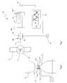
- a device 10 for measuring the content of mercury in a gas as shown schematically in FIG Fig. 1 has a light source 12 according to the invention for the emission of mercury spectral lines along an optical axis 14.
- the light source 12 which in Fig. 2 more detailed but still shown schematically is formed as an electrodeless gas discharge lamp and includes a discharge tube 12-1, in which a gas discharge burns.
- the light source is shown so that the optical axis 14 is perpendicular to the plane of the drawing.
- the gas discharge tube 12-1 has a cylindrical discharge area 12-4 and a spherical portion 12-5.
- a mercury supply in the spherical section 12-5 is a mercury supply, so that arise in the gas discharge, the mercury spectral lines.
- the mercury is preferably mercury with a natural isotope distribution.
- the gas discharge is ignited and maintained by two electrodes 12-2 and 12-3 disposed outside the discharge tube 12-1 on the cylindrical discharge portion 12-4.
- electrodes 12-2 are at the electrodes and 12-3, a high frequency voltage of a frequency of about 200 to 250 MHz and an amplitude of 4 to 8V.
- Each electrode 12-2 and 12-3 has a flat, disk-shaped holding portion 12-6 and 12-7, each having an opening 12-8 and 12-9.
- the cylindrical discharge region 12-4 of the gas discharge tube 12-1 is held in a form-fitting manner.
- the holding portions 12-6 and 12-7 are aligned parallel to each other, and the cylindrical discharge portion 12-4 lies with its cylinder axis perpendicular to the holding portions 12-6 and 12-7.
- the holding portions 12-6 and 12-7 have a material thickness of about 0.15 mm and are spaced about 3 mm apart. They are preferably made of copper as a good electrical conductor.
- the gas discharge tube 12-1 of the light source 12 is in a magnetic field as homogeneous as possible, which is generated by a magnet 15 and which is aligned at the location of light generation perpendicular to the optical axis.
- the splitting of the spectral lines is large enough and the spectral lines remain sharp, so are spectrally shifted by the same amount at each location in the lamp, a sufficiently strong and homogeneous magnetic field must be generated.
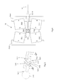
- the magnet 15 which generates the homogeneous magnetic field is constructed as a whole of four individual magnets 15-1 to 15-4, so that a north pole on one side of the gas discharge tube 12-1 (in FIG Fig. 4 above the gas discharge tube) and a south pole on the opposite side (in Fig. 4 below the gas discharge tube) is arranged.
- the north pole of the magnet 15 is then formed by the two partial magnets 15-1 and 15-2, the north poles facing each other.
- the south pole of the magnet 15 is formed by the two south poles of the partial magnets 15-3 and 15-4. Between The opposite two north poles of the partial magnets 15-1 and 15-2 and between the opposite south poles of the partial magnets 15-3 and 15-4, a gap is formed in each case, which widens toward the gas discharge tube 12-1 out. Both gaps are preferably filled in each case with an iron core 15-5 and 15-6, wherein the shape of the ends of the iron cores, which face the gas discharge tube 12-1, are concave in the illustrated cross section.
- the magnets 15-1 to 15-4 are held by brackets 15-8 and 15-9, which are preferably formed of iron, to the magnetic field between the part of the magnets 15-1 and 15-4 or 15-2 and 15th -3 in a suitable manner.
- the holder 15-9 has an opening 15-10 through which the light generated in the gas discharge tube 12-1 can pass outwardly and into the device 10 along the optical axis 14.
- Fig. 6 shows a generated by the gas discharge lamp 12 mercury spectrum.
- the spectral lines which are printed in bold, correspond to the ⁇ component, with the individual spectral lines of the ⁇ component corresponding to the different transitions of the different isotopes.
- the individual lines are characterized by the respective mass number of the isotopes.
- the spectral lines of the ⁇ + component and towards lower frequencies are the spectral lines of the ⁇ component.
- the magnetic field at the location of the gas discharge is so strong that the spectral distributions of the ⁇ + and ⁇ - components do not overlap with the distribution of the ⁇ component.
- the magnetic field is about 1 to 1.5 Tesla.
- the spectral line of 199 Hg of the ⁇ component which is designated by the reference numeral 16 and corresponds to the spectral line with the highest energy of the ⁇ component, which is designated by reference numeral 18, is shifted so far to lower frequencies in that it is clearly separated from the spectral line of the ⁇ component indicated by the reference numeral 20 and the spectral line corresponds to the lowest energy of the ⁇ component, ie the spectral line of 204 Hg.
- the sufficient separation is important because the ⁇ component ultimately provides the measurand since the nondisplaced ⁇ component is absorbed and the shifted ⁇ components form a reference because the shifted spectral components are not absorbed, as is in principle already from the prior art ( US 3,914,054 ) is known.
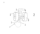
- FIG. 5 Yet another embodiment of the light source 12 according to the invention, for generating the Hg spectral lines.
- the gas discharge tube 12-1 and the electrodes 12-2 and 12-3 are constructed as in the previous embodiment.
- the magnets are now formed as ring magnets 150-1 and 150-2 and disposed on opposite sides of the gas discharge tube 12-1.
- the north pole of one ring magnet 150-2 is located at the outer edge of the ring and the corresponding south pole is reversed at the inner and the other magnet 150-1.
- Fig. 5 is not a true to scale representation, but is only schematically indicate the structure. In particular, the distances between the two ring magnets 150-1 and 150-2 to each other are not shown to scale.
- the light generated in the light source 12 contains the Zeeman components of the mercury spectral lines accordingly Fig. 6 as already explained.
- the light then passes through an optical separation device 22, which is here designed as a photoelastic modulator 24, in which, due to the birefringent properties of the modulator 24, the linearly polarized ⁇ component influences it differently becomes, as the perpendicular polarized ⁇ + and ⁇ - components.
- This different influencing takes place in the rhythm of an AC voltage applied to a piezo 26, which is provided by a voltage supply 28.
- the photoelastic modulator 24 with a polarizer, not shown in detail, the polarization of the ⁇ components is rotated on the one hand and at certain times only the ⁇ + and ⁇ components are transmitted and at certain other times only the ⁇ component.
- a temporal separation of the ⁇ components on the one hand and ⁇ + and ⁇ components on the other hand takes place.
- the light then passes through a measuring cell 30 with the mercury contamination to be measured contained therein.
- the measuring cell optionally has a heater 32.
- the unshifted spectral lines of the ⁇ component undergo absorption in the measuring cell 30 at the mercury atoms, whereas the shifted ⁇ + and ⁇ components do not undergo absorption due to the energy shift, so that the light of these lines can serve as a reference light.
- the light is received on the light receiver 34 and fed to a lock-in amplifier 38, which is triggered by the alternating voltage supplied to the photoelastic modulator 24.
- a signal is then obtained via the lock-in amplifier, as shown qualitatively in FIG Fig. 1 with the reference numeral 40 is shown.
- the light receiver 34 thus alternately receives reference light and the non-absorbed part of the measuring light with the frequency of the modulator control voltage, so that the difference thereof, ie the amplitude of the curve 40, is a measure of the absorption in the measuring cell 30, and thus a measure for the mercury concentration, so that from this signal, the concentration of mercury in the gas to be examined can be determined.
Landscapes
- Physics & Mathematics (AREA)
- Electromagnetism (AREA)
- Engineering & Computer Science (AREA)
- Plasma & Fusion (AREA)
- Investigating Or Analysing Materials By Optical Means (AREA)
- Vessels And Coating Films For Discharge Lamps (AREA)
Abstract
Description
- Die Erfindung betrifft eine Gasentladungslampe nach dem Oberbegriff des Anspruchs 1 sowie eine Lichtquelle mit einer solchen Gasentladungslampe, die vorzugsweise als Quecksilberspektrallampe dient.
- Aus der
US 5,013,966 ist eine gattungsgemäße Gasentladungslampe mit externen Elektroden bekannt. Bei dieser sind die Elektroden als Ringelektroden ausgebildet und umfassen jeweils einen zylindrischen Abschnitt der Entladungsröhre. Die Ringelektroden sind dabei relativ großflächig nach Art von Schellen ausgebildet. Allen bekannten Gasentladungslampen gemeinsam ist die begrenzte Lebensdauer, die sich insbesondere durch eine Schwärzung der Innenseite der Entladungsröhre ergibt. Dies gilt insbesondere für Quecksilberlampen, denn vermutlich werden Hg-lonen in die Quarzglasoberfläche der Entladungsröhre eingetragen und reagieren dort zu Quecksilberoxid. Dieser Vorgang ist umso effektiver, je höher die Geschwindigkeit ist, mit der die Ionen in die Oberfläche einschlagen. Diese Geschwindigkeit hängt ab vom elektrischen Feld senkrecht zur Oberfläche. - Ausgehend von diesem Stand der Technik ist es Aufgabe der Erfindung, eine verbesserte Gasentladungslampe mit externen Elektroden bereitzustellen, die eine höhere Lebensdauer hat.
- Diese Aufgabe wird gelöst durch eine Gasentladungslampe mit den Merkmalen des Anspruchs 1.
- Die erfindungsgemäße Gasentladungslampe umfasst eine Gasentladungsröhre mit einem zylindrischen Entladungsbereich und zwei Elektroden, die auf der Außenseite der Gasentladungsröhre angeordnet sind, wobei jede Elektrode einen ebenen, scheibenförmigen Halteabschnitt aufweist, der jeweils eine Öffnung enthält und wobei der zylindrische Entladungsbereich in den Öffnungen formschlüssig aufgenommen ist, wobei die Zylinderachse des zylindrischen Entladungsbereichs senkrecht zu den ebenen Halteabschnitten liegt.
- Es hat sich gezeigt, dass erheblich weniger Schwärzung auf der Innenseite der Gasentladungsröhre auftritt, wenn die Elektroden in der erfindungsgemäßen Weise ausgebildet sind und nur ein schmaler Bereich der Elektrode, nämlich die Innenseiten der Ränder der Öffnungen, an der Gasentladungsröhre anliegen. Dadurch erhöht sich auch die Lebensdauer erheblich. Versuche mit Quecksilberspektrallampen, in denen Vergleichsmessungen gemacht wurden mit identischen Gasentladungsröhren aber verschiedenen Elektrodenformen, nämlich einmal die bekannte nach dem Stand der Technik, in der die Elektroden schellenartig die zylindrische Gasentladungsröhre umfassen und einmal in der erfindungsgemäßen Ausgestaltung, haben ergeben, dass die Lebensdauer um mehr als einen Faktor 6 gesteigert werden konnte. Ein möglicher Teil der Erklärung für die lange Lebensdauer ist vermutlich, dass das elektromagnetische Feld, das sich zwischen den ebenen Halteabschnitten mit dieser speziellen Geometrie, also flache Scheiben, die parallel zueinander angeordnet sind, bildet und die Anordnung der Entladungsröhre senkrecht dazu, dazu beiträgt, dass eine geringere Schwärzung auftritt.
- In einer Ausführungsform haben sich eine Materialstärke der Halteabschnitte von ca. 0,15 mm und ein Abstand der Halteabschnitte von ca. 3mm als besonders vorteilhaft herausgestellt.
- Insbesondere bei der Verwendung der Gasentladungslampe als Quecksilberspektrallampe werden häufig die Zeeman Komponenten der Spektrallinien benötigt, so dass die Erfindung auch eine Lichtquelle mit der erfindungsgemäßen Gasentladungslampe umfasst, wobei Magnete vorgesehen sind, zwischen denen ein weitgehend homogenes Magnetfeld erzeugbar ist.
- Damit das erzeugte Magnetfeld besonders homogen ist, ist in einer Ausführungsform der erfindungsgemäßen Lichtquelle vorgesehen, dass ein Nordpol eines Magneten auf einer Seite der Gasentladungsröhre angeordnet ist und ein Südpol eines zweiten Magneten auf der gegenüberliegenden Seite angeordnet ist und sowohl der Nordpol als auch der Südpol aus zwei Teilmagneten gebildet sind, deren gleichnamige Pole gegenüberliegen und den Nord- bzw. Südpol bilden, wobei jeweils zwischen den gegenüberliegenden beiden Nordpolen bzw. gegenüberliegenden Südpolen ein Spalt gebildet ist, der sich zur Gasentladungsröhre hin weitet. Weitere Erhöhung der Homogenität kann erreicht werden, wenn die Spalte jeweils mit einem Eisenkern ausgefüllt sind, wobei bevorzugt die Form des Endes des Eisenkerns, das der Gasentladungsröhre zugewandt ist, konkav ausgebildet ist.
- In einer anderen Ausführungsform der Lichtquelle sind die Magnete auf gegenüberliegenden Seiten der Gasentladungsröhre angeordnet und als Ringmagnete ausgebildet, deren einer Pol am Innenrand und der andere am Außenrand liegen. Derartige Ringmagnete sind im Handel erhältlich und in der Lichtquelle in konstruktiv einfacher Weise zu lagern, so dass die Lichtquelle verglichen mit der vorgenannten Ausführungsform in relativ einfacher Weise aufgebaut sein kann.
- Bei Einsatz der erfindungsgemäßen Gasentladungslampe als Quecksilberspektrallampe besteht bevorzugt die Gasentladungsröhre aus einem Quarzglas. Eine solche Quecksilberspektrallampe wird bevorzugt eingesetzt zur Messung der Quecksilberkonzentration eines Gases.
- Im Folgenden wird die Erfindung anhand eines Ausführungsbeispiels unter Bezugnahme auf die Zeichnung im Einzelnen erläutert. In der Zeichnung zeigen:
- Fig. 1
- eine schematische Darstellung einer Vorrichtung zur Messung einer Konzentration eines Stoffes in einem Gas mit einer erfindungsgemäßen Lichtquelle;
- Fig. 2
- eine schematische und etwas detailliertere Darstellung der erfindungsgemäßen Lichtquelle aus
Fig. 1 ; - Fig. 3
- eine erfindungsgemäße Gasentladungslampe in perspektivischer Ansicht;
- Fig. 4
- eine weitere detailliertere Darstellung der Lichtquelle mit Gasentladungslampe im Querschnitt;
- Fig. 5
- eine andere Ausführungsform der Lichtquelle mit Gasentladungslampe;
- Fig. 6
- ein Quecksilberspektrum der Lichtquelle.
- Eine Vorrichtung 10 zur Messung des Quecksilbergehalts in einem Gas, wie sie schematisch in
Fig. 1 dargestellt ist, weist eine erfindungsgemäße Lichtquelle 12 zur Aussendung von Quecksilberspektrallinien entlang einer optischen Achse 14 auf. - Die erfindungsgemäße Lichtquelle 12, die in
Fig. 2 detaillierter aber immer noch schematisch dargestellt ist, ist als elektrodenlose Gasentladungslampe ausgebildet und umfasst eine Entladungsröhre 12-1, in der eine Gasentladung brennt. InFig. 2 ist die Lichtquelle so dargestellt, dass die optische Achse 14 senkrecht zur Zeichenebene liegt. - Wie insbesondere in
Fig. 3 erkennbar, weist die Gasentladungsröhre 12-1 einen zylindrischen Entladungsbereich 12-4 und einen kugelförmigen Abschnitt 12-5 auf. In dem kugelförmigen Abschnitt 12-5 befindet sich ein Quecksilbervorrat, so dass in der Gasentladung die Quecksilberspektrallinien entstehen. Bei dem Quecksilber handelt es sich bevorzugt um Quecksilber mit einer natürlichen Isotopenverteilung. Die Gasentladung wird gezündet und aufrechterhalten durch zwei Elektroden 12-2 und 12-3, die außerhalb der Entladungsröhre 12-1 an dem zylindrischen Entladungsbereich 12-4 angeordnet sind. Typischerweise liegt an den Elektroden 12-2 und 12-3 eine Hochfrequenzspannung einer Frequenz von etwa 200 bis 250 MHz und eine Amplitude von 4 bis 8 V an. - Jede Elektrode 12-2 und 12-3 weist erfindungsgemäß einen ebenen, scheibenförmigen Halteabschnitt 12-6 und 12-7 auf, die jeweils eine Öffnung 12-8 und 12-9 aufweisen. In den Öffnungen 12-8 und 12-9 ist der zylindrische Entladungsbereich 12-4 der Gasentladungsröhre 12-1 formschlüssig gehalten. Die Halteabschnitte 12-6 und 12-7 sind parallel zueinander ausgerichtet und der zylindrische Entladungsbereich 12-4 liegt mit seiner Zylinderachse senkrecht zu den Halteabschnitten 12-6 und 12-7.
- In dem Ausführungsbeispiel haben die Halteabschnitte 12-6 und 12-7 eine Materialstärke von ca. 0,15 mm und sind ca. 3 mm voneinander beabstandet. Sie bestehen bevorzugt aus Kupfer als gutem elektrischen Leiter.
- Die Gasentladungsröhre 12-1 der Lichtquelle 12 befindet sich in einem möglichst homogenen Magnetfeld, das von einem Magneten 15 erzeugt wird und das am Ort der Lichterzeugung senkrecht zur optischen Achse ausgerichtet ist. Dadurch werden aufgrund des Zeeman-Effektes die σ+, σ- und die π polarisierten Zeeman Komponenten der Spektrallinien erzeugt.
- Damit die Aufspaltung der Spektrallinien groß genug ist und die Spektrallinien scharf bleiben, also an jedem Ort in der Lampe um den gleichen Betrag spektral verschoben werden, muss ein ausreichend starkes und homogenes Magnetfeld erzeugt werden. Dafür ist der Magnet 15 in besonderer Weise ausgebildet, wie dies in
Fig. 4 dargestellt ist. Der Magnet 15, der das homogene Magnetfeld erzeugt, ist insgesamt aus vier einzelnen Magneten 15-1 bis 15-4 aufgebaut, so dass ein Nordpol auf einer Seite der Gasentladungsröhre 12-1 (inFig. 4 oberhalb der Gasentladungsröhre) und ein Südpol auf der gegenüberliegenden Seite (inFig. 4 unterhalb der Gasentladungsröhre) angeordnet ist. Der Nordpol des Magneten 15 ist dann durch die beiden Teilmagnete 15-1 und 15-2 gebildet, deren Nordpole einander gegenüberliegen. In entsprechender Weise ist der Südpol des Magneten 15 gebildet durch die beiden Südpole der Teilmagnete 15-3 und 15-4. Zwischen den gegenüberliegenden beiden Nordpolen der Teilmagnete 15-1 und 15-2 sowie zwischen den gegenüberliegenden Südpolen der Teilmagnete 15-3 und 15-4 ist jeweils ein Spalt gebildet, der sich zur Gasentladungsröhre 12-1 hin weitet. Beide Spalte sind bevorzugt jeweils mit einem Eisenkern 15-5 und 15-6 ausgefüllt, wobei die Form der Enden der Eisenkerne, die der Gasentladungsröhre 12-1 zugewandt sind, im dargestellten Querschnitt konkav ausgebildet sind. Durch diese Ausführungsform des Magneten 15 mit seinen Teilmagneten und den Eisenkernen kann ein besonders homogenes Magnetfeld am Ort der Gasentladung, das durch gestrichelte Linien 15-7 angedeutet ist, erzeugt werden. - Von außen werden die Magnete 15-1 bis 15-4 gehalten durch Halterungen 15-8 und 15-9, die bevorzugt aus Eisen ausgebildet sind, um das Magnetfeld zwischen den Teilmagneten 15-1 und 15-4 bzw. 15-2 und 15-3 in geeigneter Weise zu leiten. Die Halterung 15-9 weist eine Öffnung 15-10 auf, durch die das in der Gasentladungsröhre 12-1 erzeugte Licht nach außen und in die Vorrichtung 10 entlang der optischen Achse 14 treten kann.
-
Fig. 6 zeigt ein von der Gasentladungslampe 12 erzeugtes Quecksilberspektrum. Die Spektrallinien, die fetter gedruckt sind, entsprechen der π Komponente, wobei die einzelnen Spektrallinien der π Komponente den verschiedenen Übergängen der verschiedenen Isotope entsprechen. Die einzelnen Linien sind durch die jeweilige Massenzahl der Isotope gekennzeichnet. Zu höheren Frequenzen hin liegen die Spektrallinien der σ+ Komponente und zu niedrigeren Frequenzen hin die Spektrallinien der σ- Komponente. Das Magnetfeld ist am Ort der Gasentladung so stark, dass die spektralen Verteilungen der σ+ und σ- Komponente sich nicht mit der Verteilung der π Komponente überschneiden. Typischerweise beträgt das Magnetfeld dafür etwa 1 bis 1,5 Tesla. Das bedeutet, dass beispielsweise die Spektrallinie von 199Hg der σ- Komponente, die mit der Bezugsziffer 16 gekennzeichnet ist und die der Spektrallinie mit der höchsten Energie der π Komponente entspricht, die mit der Bezugsziffer 18 gekennzeichnet ist, soweit zu niedrigeren Frequenzen hin verschoben ist, dass sie deutlich getrennt ist von der Spektrallinie der π Komponente, die mit der Bezugsziffer 20 gekennzeichnet ist und der Spektrallinie mit niedrigster Energie der π Komponente entspricht, also der Spektrallinie von 204Hg. - Wie weiter unten erläutert wird, ist die ausreichende Trennung deswegen wichtig, weil die π Komponente letztendlich die Messgröße liefert, da die unverschobene π Komponente absorbiert wird und die verschobenen σ Komponenten eine Referenzgröße bilden, da die verschobenen Spektralkomponenten nicht absorbiert werden, wie das prinzipiell bereits aus dem Stand der Technik (
US 3,914,054 ) bekannt ist. - Schließlich zeigt
Fig. 5 noch eine andere Ausführungsform der erfindungsgemäßen Lichtquelle 12, zur Erzeugung der Hg Spektrallinien. Die Gasentladungsröhre 12-1 sowie die Elektroden 12-2 und 12-3 sind wie in dem vorherigen Ausführungsbeispiel aufgebaut. Die Magnete allerdings sind jetzt als Ringmagnete 150-1 und 150-2 ausgebildet und auf gegenüberliegenden Seiten der Gasentladungsröhre 12-1 angeordnet. Der Nordpol des einen Ringmagnets 150-2 befindet sich am äußeren Rand des Rings und der entsprechende Südpol am inneren und bei dem anderen Magnet 150-1 umgekehrt. Auf diese Weise entsteht mit Hilfe zweier einfacher Ringmagnete am Ort der Gasentladung ein relativ homogenes Magnetfeld.Fig. 5 stellt keine maßstabsgetreue Darstellung dar, sondern soll lediglich schematisch den Aufbau andeuten. Insbesondere die Abstände der beiden Ringmagnete 150-1 und 150-2 zueinander sind nicht maßstabsgerecht gezeigt. - Zum vollständigen Verständnis wird im Folgenden der Einsatz der erfindungsgemäßen Gasentladungslampe in der Vorrichtung 10 zum Bestimmen des Quecksilbergehaltes eines Gases im Einzelnen erläutert.
- Das in der Lichtquelle 12 erzeugte Licht enthält die Zeeman Komponenten der Quecksilberspektrallinien entsprechend
Fig. 6 , wie dies bereits erläutert wurde. - Das Licht durchläuft dann eine optische Trennvorrichtung 22, die hier als photoelastischer Modulator 24 ausgebildet ist, in dem aufgrund der doppelbrechenden Eigenschaften des Modulators 24 die linear polarisierte π Komponente anders beeinflusst wird, als die senkrecht dazu polarisierten σ+ und σ- Komponenten. Diese unterschiedliche Beeinflussung erfolgt im Rhythmus einer an einen Piezo 26 angelegten Wechselspannung, die durch eine Spannungsversorgung 28 bereitgestellt wird. In Kombination des photoelastischen Modulators 24 mit einem im Einzelnen nicht dargestellten Polarisator wird einerseits die Polarisation der σ Komponenten gedreht und zu bestimmten Zeiten nur die σ+ und σ- Komponenten durchgelassen und zu bestimmten anderen Zeiten nur die π Komponente. Somit erfolgt mit Hilfe des photoelastischen Modulators 24 eine zeitliche Auftrennung der π Komponenten einerseits und σ+ und σ- Komponenten andererseits.
- Danach durchläuft das Licht eine Messzelle 30 mit der darin enthaltenen, zu messenden Quecksilberverunreinigung. Die Messzelle weist gegebenenfalls eine Heizung 32 auf. Die unverschobenen Spektrallinien der π Komponente erfahren in der Messzelle 30 eine Absorption an den Quecksilberatomen, wohingegen die verschobenen σ+ und σ- Komponenten keine Absorption aufgrund der Energieverschiebung erfahren, so dass das Licht dieser Linien als Referenzlicht dienen kann.
- Schließlich wird das Licht auf dem Lichtempfänger 34 empfangen und einem Lock-In Verstärker 38 zugeführt, der mit der dem photoelastischen Modulator 24 zugeführten Wechselspannung getriggert ist. Im Ergebnis wird dann über den Lock-In Verstärker ein Signal erhalten, wie dies qualitativ in
Fig. 1 mit der Bezugsziffer 40 gezeigt ist. Der Lichtempfänger 34 empfängt also abwechselnd Referenzlicht und den nicht absorbierten Teil des Messlichts mit der Frequenz der Modulator-steuerspannung, so dass die Differenz hiervon, also die Amplitude der Kurve 40, ein Maß für die Absorption in der Messzelle 30 ist, und damit ein Maß für die Quecksilberkonzentration, so dass aus diesem Signal sich die Konzentration des Quecksilbers in dem zu untersuchenden Gas bestimmen lässt. -
- 10
- Vorrichtung
- 12
- Lichtquelle, Gasentladungslampe
- 12-1
- Entladungsröhre
- 12-2 und 12-3
- Elektrode
- 12-4
- zylindrischer Entladungsbereich
- 12-5
- kugelförmige Abschnitt
- 12-6 und 12-7
- scheibenförmigen Halteabschnitt
- 12-8 und 12-9
- Öffnung
- 14
- optische Achse
- 15
- Magnet
- 15-1 bis 15-4
- Teilmagnete
- 15-5 bis 15-6
- Eisenkerne
- 15-7
- Magnetfeldlinien
- 15-8 und 15-9
- Halterungen
- 15-10
- Öffnung
- 16, 18, 20
- Spektrallinien
- 22
- optische Trennvorrichtung
- 24
- Modulator
- 26
- Piezo
- 28
- Spannungsversorgung
- 30
- Messzelle
- 32
- Heizung
- 34
- Lichtempfänger
- 38
- Lock-In Verstärker
- 40
- Signal
- 150-1 und 150-2
- Ringmagnete
Claims (7)
- Gasentladungslampe mit einer Gasentladungsröhre (12-1) mit einem zylindrischen Entladungsbereich (12-4), mit zwei Elektroden (12-2, 12-3), die auf der Außenseite der Gasentladungsröhre (12-1) angeordnet sind, dadurch gekennzeichnet, dass jede Elektrode (12-2, 12-3) einen ebenen, scheibenförmigen Halteabschnitt (12-6, 12-7) aufweist, der jeweils eine Öffnung (12-8, 12-9) enthält und dass der zylindrische Entladungsbereich (12-4) in den Öffnungen (12-8, 12-9) formschlüssig aufgenommen ist, wobei die Zylinderachse des zylindrischen Entladungsbereichs (12-4) senkrecht zu den ebenen Halteabschnitten (12-6, 12-7) liegt.
- Gasentladungslampe nach einem der vorhergehenden Ansprüche, dadurch gekennzeichnet, dass der Halteabschnitt (12-6, 12-7) eine Materialstärke von ca. 0,15 mm und die Halteabschnitte (12-6, 12-7) der beiden Elektroden (12-2, 12-3) ca. 3mm beabstandet sind.
- Lichtquelle mit einer Gasentladungslampe (12) nach einem der vorhergehenden Ansprüche, dadurch gekennzeichnet, dass Magnete (15, 15-1 bis 15-4, 150) vorgesehen sind, zwischen denen ein weitgehend homogenes Magnetfeld (15-7) erzeugbar ist.
- Lichtquelle nach Anspruch 4, dadurch gekennzeichnet, dass ein Nordpol eines Magneten auf einer Seite der Gasentladungsröhre und ein Südpol eines zweiten Magneten auf der gegenüberliegenden Seite angeordnet ist und sowohl der Nordpol als auch der Südpol aus zwei Teilmagneten (15-1 und 15-2 bzw. 15-3 und 15-4) gebildet sind, deren gleichnamigen Pole gegenüberliegen und den Nord- bzw. Südpol bilden, wobei jeweils zwischen den gegenüberliegenden beiden Nordpolen bzw. gegenüberliegenden Südpolen ein Spalt gebildet ist, der sich zur Gasentladungsröhre (12-1) hin weitet.
- Lichtquelle nach Anspruch 5, dadurch gekennzeichnet, dass die Spalte jeweils mit einem Eisenkern (15-5, 15-6) ausgefüllt sind, wobei bevorzugt die Form des Endes des Eisenkerns, das der Gasentladungsröhre (12-1) zugewandt ist, konkav ausgebildet ist.
- Lichtquelle nach Anspruch 4, dadurch gekennzeichnet, dass die Magnete auf gegenüberliegenden Seiten der Gasentladungsröhre (12-1) angeordnet sind und als Ringmagnete (150-1 und 150-2) ausgebildet sind, deren einer Pol am Innenrand und der andere am Außenrand liegen.
- Quecksilberspektrallampe mit einer Lichtquelle nach einem der vorhergehenden Ansprüche 4 bis 6, dadurch gekennzeichnet, dass die Gasentladungsröhre (12-1) aus einem Quarzglas besteht und Quecksilber enthält.
Applications Claiming Priority (1)
| Application Number | Priority Date | Filing Date | Title |
|---|---|---|---|
| DE102009059705A DE102009059705A1 (de) | 2009-12-18 | 2009-12-18 | Gasentladungslampe |
Publications (2)
| Publication Number | Publication Date |
|---|---|
| EP2337059A1 true EP2337059A1 (de) | 2011-06-22 |
| EP2337059B1 EP2337059B1 (de) | 2012-04-04 |
Family
ID=43728980
Family Applications (1)
| Application Number | Title | Priority Date | Filing Date |
|---|---|---|---|
| EP10192074A Active EP2337059B1 (de) | 2009-12-18 | 2010-11-22 | Gasentladungslampe mit Außenelektrode |
Country Status (7)
| Country | Link |
|---|---|
| US (1) | US8482201B2 (de) |
| EP (1) | EP2337059B1 (de) |
| JP (1) | JP5525431B2 (de) |
| KR (1) | KR101665925B1 (de) |
| CN (1) | CN102122603B (de) |
| AT (1) | ATE552608T1 (de) |
| DE (1) | DE102009059705A1 (de) |
Families Citing this family (4)
| Publication number | Priority date | Publication date | Assignee | Title |
|---|---|---|---|---|
| US11173692B2 (en) | 2019-12-19 | 2021-11-16 | Prc-Desoto International, Inc. | Free radical polymerizable adhesion-promoting interlayer compositions and methods of use |
| US11608458B2 (en) | 2019-12-19 | 2023-03-21 | Prc-Desoto International, Inc. | Adhesion-promoting interlayer compositions containing organic titanates/zirconates and methods of use |
| US11624007B2 (en) | 2020-01-29 | 2023-04-11 | Prc-Desoto International, Inc. | Photocurable adhesion-promoting compositions and methods of use |
| CN113725052B (zh) * | 2021-07-28 | 2024-07-02 | 枝江久熠照明电器有限公司 | 一种紫外线灯管加工用拉伸注汞一体装置 |
Citations (4)
| Publication number | Priority date | Publication date | Assignee | Title |
|---|---|---|---|---|
| US3914054A (en) | 1972-09-13 | 1975-10-21 | Us Energy | Zeeman effect absorption spectrometer |
| EP0329143A1 (de) * | 1988-02-17 | 1989-08-23 | Mitsubishi Denki Kabushiki Kaisha | Entladungslampe |
| EP0897191A2 (de) * | 1997-08-11 | 1999-02-17 | Osram Sylvania Inc. | Lampen für Videoprojektion |
| US20090134770A1 (en) * | 2007-11-23 | 2009-05-28 | Ki-Duck Park | Fluorescent lamp and liquid crystal display device having the same |
Family Cites Families (16)
| Publication number | Priority date | Publication date | Assignee | Title |
|---|---|---|---|---|
| GB1420044A (en) * | 1972-09-13 | 1976-01-07 | Us Energy Research Dev Adminis | Zeeman effect absorption spectrometer |
| US4457623A (en) * | 1981-02-23 | 1984-07-03 | The Perkin-Elmer Corporation | Atomic absorption spectrophotometer providing background correction using the Zeeman effect |
| EP0948030A3 (de) * | 1998-03-30 | 1999-12-29 | Toshiba Lighting & Technology Corporation | Edelgasgefüllte Entladungslampe, Leuchtschaltung und Leuchtvorrichtung |
| JP4091166B2 (ja) * | 1998-05-27 | 2008-05-28 | オスラム・メルコ株式会社 | 光源装置 |
| US6674250B2 (en) * | 2000-04-15 | 2004-01-06 | Guang-Sup Cho | Backlight including external electrode fluorescent lamp and method for driving the same |
| JP3080172U (ja) * | 2001-03-09 | 2001-09-14 | ドン パク スン | 放電装置及び当該装置を用いたプラズマガス発生装置 |
| JP2003017005A (ja) | 2001-06-27 | 2003-01-17 | Harison Toshiba Lighting Corp | 低圧放電ランプ |
| TW558732B (en) * | 2001-09-19 | 2003-10-21 | Matsushita Electric Industrial Co Ltd | Light source apparatus and liquid crystal display apparatus using the same |
| JP3927107B2 (ja) * | 2002-09-25 | 2007-06-06 | ハリソン東芝ライティング株式会社 | 低圧放電ランプ |
| JP4027849B2 (ja) * | 2003-06-19 | 2007-12-26 | ハリソン東芝ライティング株式会社 | 低圧放電ランプ |
| JP4249689B2 (ja) | 2003-11-25 | 2009-04-02 | Necライティング株式会社 | 外部電極型放電ランプおよびその製造方法 |
| CN1910734A (zh) * | 2004-01-22 | 2007-02-07 | 松下电器产业株式会社 | 外部电极型放电灯、外部电极型放电灯的制造方法以及背光单元 |
| CN100426092C (zh) * | 2006-03-01 | 2008-10-15 | 友达光电股份有限公司 | 背光模块及其光源结构 |
| WO2008129481A2 (en) * | 2007-04-24 | 2008-10-30 | Koninklijke Philips Electronics N.V. | Low-pressure gas discharge lamp |
| KR20090078155A (ko) * | 2008-01-14 | 2009-07-17 | 삼성코닝정밀유리 주식회사 | 관형 램프 및 이를 구비하는 백라이트 유닛 |
| EA201001219A1 (ru) * | 2008-02-25 | 2011-02-28 | Йехи-Ор Лайт Криэйшн Лтд. | Высокоэффективная газонаполненная лампа |
-
2009
- 2009-12-18 DE DE102009059705A patent/DE102009059705A1/de not_active Ceased
-
2010
- 2010-11-22 EP EP10192074A patent/EP2337059B1/de active Active
- 2010-11-22 AT AT10192074T patent/ATE552608T1/de active
- 2010-12-09 US US12/963,932 patent/US8482201B2/en active Active
- 2010-12-16 CN CN201010598110.4A patent/CN102122603B/zh active Active
- 2010-12-16 JP JP2010280061A patent/JP5525431B2/ja active Active
- 2010-12-17 KR KR1020100129977A patent/KR101665925B1/ko active Active
Patent Citations (5)
| Publication number | Priority date | Publication date | Assignee | Title |
|---|---|---|---|---|
| US3914054A (en) | 1972-09-13 | 1975-10-21 | Us Energy | Zeeman effect absorption spectrometer |
| EP0329143A1 (de) * | 1988-02-17 | 1989-08-23 | Mitsubishi Denki Kabushiki Kaisha | Entladungslampe |
| US5013966A (en) | 1988-02-17 | 1991-05-07 | Mitsubishi Denki Kabushiki Kaisha | Discharge lamp with external electrodes |
| EP0897191A2 (de) * | 1997-08-11 | 1999-02-17 | Osram Sylvania Inc. | Lampen für Videoprojektion |
| US20090134770A1 (en) * | 2007-11-23 | 2009-05-28 | Ki-Duck Park | Fluorescent lamp and liquid crystal display device having the same |
Also Published As
| Publication number | Publication date |
|---|---|
| JP2011129524A (ja) | 2011-06-30 |
| US8482201B2 (en) | 2013-07-09 |
| KR101665925B1 (ko) | 2016-10-13 |
| JP5525431B2 (ja) | 2014-06-18 |
| CN102122603A (zh) | 2011-07-13 |
| CN102122603B (zh) | 2014-11-12 |
| DE102009059705A1 (de) | 2011-06-22 |
| EP2337059B1 (de) | 2012-04-04 |
| US20110148294A1 (en) | 2011-06-23 |
| ATE552608T1 (de) | 2012-04-15 |
| KR20110070827A (ko) | 2011-06-24 |
Similar Documents
| Publication | Publication Date | Title |
|---|---|---|
| EP2753907B1 (de) | Lonisations - vakuummesszelle | |
| DE112009001895B4 (de) | Ionengatter eines Ionenmobilitätsspektrometers mit dualer Polarität und Verfahren dafür | |
| DE102007056584B4 (de) | Anregung der Ionen in einer ICR-Zelle mit strukturierten Trapping-Elektroden | |
| DE3605911A1 (de) | Glimmentladungslampe sowie ihre verwendung | |
| DE68926167T2 (de) | Hochauflösendes plasmamassenspektrometer | |
| CH615532A5 (de) | ||
| EP2337059B1 (de) | Gasentladungslampe mit Außenelektrode | |
| CH707685A1 (de) | Ionisations-Vakuummesszelle mit Abschirmvorrichtung. | |
| DE1937482A1 (de) | Mikrostrahlsonde | |
| DE2628422B2 (de) | Verfahren zur Massenspektroskopie | |
| EP3147634A1 (de) | Kernmagnetisches durchflussmessgerät | |
| DE68901731T2 (de) | Massenspektrometer. | |
| DE1498935C3 (de) | Massenspektrometer für Gase niedriger Massenzahl | |
| EP0221339B1 (de) | Ionen-Zyklotron-Resonanz-Spektrometer | |
| DE2737852C2 (de) | Ionenquellen zur chemischen Ionisierung | |
| DE2048862A1 (de) | Vorrichtung zur spektralphotometri sehen Analyse | |
| EP3062332A1 (de) | Verfahren und Vorrichtung zur chemischen Ionisation eines Gasgemisches | |
| EP2336748A1 (de) | Vorrichtung und Verfahren zur Messung des Quecksilbergehalts in einem Gas | |
| DE102004023382B4 (de) | Staubabscheider für Laser und Laser mit Staubabscheider | |
| DE10105773C1 (de) | Fouriertransformations-Massenspektrometer mit Bildladungsdetektor | |
| DE2329190A1 (de) | Roentgenspektrometer | |
| DE102022213860A1 (de) | Verfahren und eine Vorrichtung zur Erzeugung von polarisierten Atomen, Molekülen und deren Ionen | |
| DE102011010138B4 (de) | Kaltkathoden-Druckmessvorrichtung vom Penning-Typ | |
| DE102008058144A1 (de) | Elektrostatischer Analysator für geladene Teilchen, Spektrometer und Monochromator mit einem solchen Analysator | |
| DE1539064A1 (de) | Anordnung zur Korrektur der Ungleichfoermigkeit eines Magnetfeldes |
Legal Events
| Date | Code | Title | Description |
|---|---|---|---|
| PUAI | Public reference made under article 153(3) epc to a published international application that has entered the european phase |
Free format text: ORIGINAL CODE: 0009012 |
|
| AK | Designated contracting states |
Kind code of ref document: A1 Designated state(s): AL AT BE BG CH CY CZ DE DK EE ES FI FR GB GR HR HU IE IS IT LI LT LU LV MC MK MT NL NO PL PT RO RS SE SI SK SM TR |
|
| AX | Request for extension of the european patent |
Extension state: BA ME |
|
| 17P | Request for examination filed |
Effective date: 20110628 |
|
| RIC1 | Information provided on ipc code assigned before grant |
Ipc: H01J 65/04 20060101ALI20111005BHEP Ipc: H01J 61/067 20060101AFI20111005BHEP |
|
| GRAP | Despatch of communication of intention to grant a patent |
Free format text: ORIGINAL CODE: EPIDOSNIGR1 |
|
| GRAS | Grant fee paid |
Free format text: ORIGINAL CODE: EPIDOSNIGR3 |
|
| GRAA | (expected) grant |
Free format text: ORIGINAL CODE: 0009210 |
|
| AK | Designated contracting states |
Kind code of ref document: B1 Designated state(s): AL AT BE BG CH CY CZ DE DK EE ES FI FR GB GR HR HU IE IS IT LI LT LU LV MC MK MT NL NO PL PT RO RS SE SI SK SM TR |
|
| REG | Reference to a national code |
Ref country code: GB Ref legal event code: FG4D Free format text: NOT ENGLISH |
|
| REG | Reference to a national code |
Ref country code: CH Ref legal event code: EP |
|
| REG | Reference to a national code |
Ref country code: AT Ref legal event code: REF Ref document number: 552608 Country of ref document: AT Kind code of ref document: T Effective date: 20120415 |
|
| REG | Reference to a national code |
Ref country code: IE Ref legal event code: FG4D Free format text: LANGUAGE OF EP DOCUMENT: GERMAN |
|
| RAP2 | Party data changed (patent owner data changed or rights of a patent transferred) |
Owner name: SICK AG |
|
| REG | Reference to a national code |
Ref country code: DE Ref legal event code: R096 Ref document number: 502010000600 Country of ref document: DE Effective date: 20120606 |
|
| REG | Reference to a national code |
Ref country code: NL Ref legal event code: VDEP Effective date: 20120404 |
|
| REG | Reference to a national code |
Ref country code: DE Ref legal event code: R081 Ref document number: 502010000600 Country of ref document: DE Owner name: SICK AG, DE Free format text: FORMER OWNER: SICK MAIHAK GMBH, 79183 WALDKIRCH, DE Effective date: 20120628 |
|
| PG25 | Lapsed in a contracting state [announced via postgrant information from national office to epo] |
Ref country code: RS Free format text: LAPSE BECAUSE OF FAILURE TO SUBMIT A TRANSLATION OF THE DESCRIPTION OR TO PAY THE FEE WITHIN THE PRESCRIBED TIME-LIMIT Effective date: 20120404 |
|
| REG | Reference to a national code |
Ref country code: AT Ref legal event code: HC Ref document number: 552608 Country of ref document: AT Kind code of ref document: T Owner name: SICK AG, DE Effective date: 20120719 |
|
| LTIE | Lt: invalidation of european patent or patent extension |
Effective date: 20120404 |
|
| PG25 | Lapsed in a contracting state [announced via postgrant information from national office to epo] |
Ref country code: NO Free format text: LAPSE BECAUSE OF FAILURE TO SUBMIT A TRANSLATION OF THE DESCRIPTION OR TO PAY THE FEE WITHIN THE PRESCRIBED TIME-LIMIT Effective date: 20120704 Ref country code: CY Free format text: LAPSE BECAUSE OF FAILURE TO SUBMIT A TRANSLATION OF THE DESCRIPTION OR TO PAY THE FEE WITHIN THE PRESCRIBED TIME-LIMIT Effective date: 20120404 Ref country code: SI Free format text: LAPSE BECAUSE OF FAILURE TO SUBMIT A TRANSLATION OF THE DESCRIPTION OR TO PAY THE FEE WITHIN THE PRESCRIBED TIME-LIMIT Effective date: 20120404 Ref country code: LT Free format text: LAPSE BECAUSE OF FAILURE TO SUBMIT A TRANSLATION OF THE DESCRIPTION OR TO PAY THE FEE WITHIN THE PRESCRIBED TIME-LIMIT Effective date: 20120404 Ref country code: FI Free format text: LAPSE BECAUSE OF FAILURE TO SUBMIT A TRANSLATION OF THE DESCRIPTION OR TO PAY THE FEE WITHIN THE PRESCRIBED TIME-LIMIT Effective date: 20120404 Ref country code: SE Free format text: LAPSE BECAUSE OF FAILURE TO SUBMIT A TRANSLATION OF THE DESCRIPTION OR TO PAY THE FEE WITHIN THE PRESCRIBED TIME-LIMIT Effective date: 20120404 Ref country code: IS Free format text: LAPSE BECAUSE OF FAILURE TO SUBMIT A TRANSLATION OF THE DESCRIPTION OR TO PAY THE FEE WITHIN THE PRESCRIBED TIME-LIMIT Effective date: 20120804 Ref country code: PL Free format text: LAPSE BECAUSE OF FAILURE TO SUBMIT A TRANSLATION OF THE DESCRIPTION OR TO PAY THE FEE WITHIN THE PRESCRIBED TIME-LIMIT Effective date: 20120404 |
|
| PG25 | Lapsed in a contracting state [announced via postgrant information from national office to epo] |
Ref country code: HR Free format text: LAPSE BECAUSE OF FAILURE TO SUBMIT A TRANSLATION OF THE DESCRIPTION OR TO PAY THE FEE WITHIN THE PRESCRIBED TIME-LIMIT Effective date: 20120404 Ref country code: LV Free format text: LAPSE BECAUSE OF FAILURE TO SUBMIT A TRANSLATION OF THE DESCRIPTION OR TO PAY THE FEE WITHIN THE PRESCRIBED TIME-LIMIT Effective date: 20120404 Ref country code: GR Free format text: LAPSE BECAUSE OF FAILURE TO SUBMIT A TRANSLATION OF THE DESCRIPTION OR TO PAY THE FEE WITHIN THE PRESCRIBED TIME-LIMIT Effective date: 20120705 Ref country code: PT Free format text: LAPSE BECAUSE OF FAILURE TO SUBMIT A TRANSLATION OF THE DESCRIPTION OR TO PAY THE FEE WITHIN THE PRESCRIBED TIME-LIMIT Effective date: 20120806 |
|
| PG25 | Lapsed in a contracting state [announced via postgrant information from national office to epo] |
Ref country code: NL Free format text: LAPSE BECAUSE OF FAILURE TO SUBMIT A TRANSLATION OF THE DESCRIPTION OR TO PAY THE FEE WITHIN THE PRESCRIBED TIME-LIMIT Effective date: 20120404 Ref country code: DK Free format text: LAPSE BECAUSE OF FAILURE TO SUBMIT A TRANSLATION OF THE DESCRIPTION OR TO PAY THE FEE WITHIN THE PRESCRIBED TIME-LIMIT Effective date: 20120404 Ref country code: RO Free format text: LAPSE BECAUSE OF FAILURE TO SUBMIT A TRANSLATION OF THE DESCRIPTION OR TO PAY THE FEE WITHIN THE PRESCRIBED TIME-LIMIT Effective date: 20120404 Ref country code: SK Free format text: LAPSE BECAUSE OF FAILURE TO SUBMIT A TRANSLATION OF THE DESCRIPTION OR TO PAY THE FEE WITHIN THE PRESCRIBED TIME-LIMIT Effective date: 20120404 Ref country code: EE Free format text: LAPSE BECAUSE OF FAILURE TO SUBMIT A TRANSLATION OF THE DESCRIPTION OR TO PAY THE FEE WITHIN THE PRESCRIBED TIME-LIMIT Effective date: 20120404 Ref country code: CZ Free format text: LAPSE BECAUSE OF FAILURE TO SUBMIT A TRANSLATION OF THE DESCRIPTION OR TO PAY THE FEE WITHIN THE PRESCRIBED TIME-LIMIT Effective date: 20120404 |
|
| PLBE | No opposition filed within time limit |
Free format text: ORIGINAL CODE: 0009261 |
|
| STAA | Information on the status of an ep patent application or granted ep patent |
Free format text: STATUS: NO OPPOSITION FILED WITHIN TIME LIMIT |
|
| PG25 | Lapsed in a contracting state [announced via postgrant information from national office to epo] |
Ref country code: IT Free format text: LAPSE BECAUSE OF FAILURE TO SUBMIT A TRANSLATION OF THE DESCRIPTION OR TO PAY THE FEE WITHIN THE PRESCRIBED TIME-LIMIT Effective date: 20120404 |
|
| 26N | No opposition filed |
Effective date: 20130107 |
|
| PG25 | Lapsed in a contracting state [announced via postgrant information from national office to epo] |
Ref country code: ES Free format text: LAPSE BECAUSE OF FAILURE TO SUBMIT A TRANSLATION OF THE DESCRIPTION OR TO PAY THE FEE WITHIN THE PRESCRIBED TIME-LIMIT Effective date: 20120715 |
|
| REG | Reference to a national code |
Ref country code: DE Ref legal event code: R097 Ref document number: 502010000600 Country of ref document: DE Effective date: 20130107 |
|
| BERE | Be: lapsed |
Owner name: SICK MAIHAK G.M.B.H. Effective date: 20121130 |
|
| PG25 | Lapsed in a contracting state [announced via postgrant information from national office to epo] |
Ref country code: BG Free format text: LAPSE BECAUSE OF FAILURE TO SUBMIT A TRANSLATION OF THE DESCRIPTION OR TO PAY THE FEE WITHIN THE PRESCRIBED TIME-LIMIT Effective date: 20120704 |
|
| REG | Reference to a national code |
Ref country code: IE Ref legal event code: MM4A |
|
| PG25 | Lapsed in a contracting state [announced via postgrant information from national office to epo] |
Ref country code: BE Free format text: LAPSE BECAUSE OF NON-PAYMENT OF DUE FEES Effective date: 20121130 |
|
| PG25 | Lapsed in a contracting state [announced via postgrant information from national office to epo] |
Ref country code: IE Free format text: LAPSE BECAUSE OF NON-PAYMENT OF DUE FEES Effective date: 20121122 |
|
| PG25 | Lapsed in a contracting state [announced via postgrant information from national office to epo] |
Ref country code: AL Free format text: LAPSE BECAUSE OF FAILURE TO SUBMIT A TRANSLATION OF THE DESCRIPTION OR TO PAY THE FEE WITHIN THE PRESCRIBED TIME-LIMIT Effective date: 20120404 Ref country code: MT Free format text: LAPSE BECAUSE OF FAILURE TO SUBMIT A TRANSLATION OF THE DESCRIPTION OR TO PAY THE FEE WITHIN THE PRESCRIBED TIME-LIMIT Effective date: 20120404 |
|
| PG25 | Lapsed in a contracting state [announced via postgrant information from national office to epo] |
Ref country code: MC Free format text: LAPSE BECAUSE OF NON-PAYMENT OF DUE FEES Effective date: 20121130 Ref country code: TR Free format text: LAPSE BECAUSE OF FAILURE TO SUBMIT A TRANSLATION OF THE DESCRIPTION OR TO PAY THE FEE WITHIN THE PRESCRIBED TIME-LIMIT Effective date: 20120404 |
|
| PG25 | Lapsed in a contracting state [announced via postgrant information from national office to epo] |
Ref country code: LU Free format text: LAPSE BECAUSE OF NON-PAYMENT OF DUE FEES Effective date: 20121122 Ref country code: SM Free format text: LAPSE BECAUSE OF FAILURE TO SUBMIT A TRANSLATION OF THE DESCRIPTION OR TO PAY THE FEE WITHIN THE PRESCRIBED TIME-LIMIT Effective date: 20120404 |
|
| PG25 | Lapsed in a contracting state [announced via postgrant information from national office to epo] |
Ref country code: HU Free format text: LAPSE BECAUSE OF FAILURE TO SUBMIT A TRANSLATION OF THE DESCRIPTION OR TO PAY THE FEE WITHIN THE PRESCRIBED TIME-LIMIT Effective date: 20101122 |
|
| REG | Reference to a national code |
Ref country code: CH Ref legal event code: PL |
|
| PG25 | Lapsed in a contracting state [announced via postgrant information from national office to epo] |
Ref country code: MK Free format text: LAPSE BECAUSE OF FAILURE TO SUBMIT A TRANSLATION OF THE DESCRIPTION OR TO PAY THE FEE WITHIN THE PRESCRIBED TIME-LIMIT Effective date: 20120404 Ref country code: LI Free format text: LAPSE BECAUSE OF NON-PAYMENT OF DUE FEES Effective date: 20141130 Ref country code: CH Free format text: LAPSE BECAUSE OF NON-PAYMENT OF DUE FEES Effective date: 20141130 |
|
| REG | Reference to a national code |
Ref country code: FR Ref legal event code: PLFP Year of fee payment: 6 |
|
| REG | Reference to a national code |
Ref country code: FR Ref legal event code: PLFP Year of fee payment: 7 |
|
| REG | Reference to a national code |
Ref country code: AT Ref legal event code: MM01 Ref document number: 552608 Country of ref document: AT Kind code of ref document: T Effective date: 20151122 |
|
| PG25 | Lapsed in a contracting state [announced via postgrant information from national office to epo] |
Ref country code: AT Free format text: LAPSE BECAUSE OF NON-PAYMENT OF DUE FEES Effective date: 20151122 |
|
| REG | Reference to a national code |
Ref country code: FR Ref legal event code: PLFP Year of fee payment: 8 |
|
| PGFP | Annual fee paid to national office [announced via postgrant information from national office to epo] |
Ref country code: DE Payment date: 20251118 Year of fee payment: 16 |
|
| PGFP | Annual fee paid to national office [announced via postgrant information from national office to epo] |
Ref country code: GB Payment date: 20251120 Year of fee payment: 16 |
|
| REG | Reference to a national code |
Ref country code: DE Ref legal event code: R081 Ref document number: 502010000600 Country of ref document: DE Owner name: ENDRESS+HAUSER SICK GMBH+CO. KG, DE Free format text: FORMER OWNER: SICK AG, 79183 WALDKIRCH, DE |
|
| PGFP | Annual fee paid to national office [announced via postgrant information from national office to epo] |
Ref country code: FR Payment date: 20251125 Year of fee payment: 16 |
|
| REG | Reference to a national code |
Ref country code: GB Ref legal event code: 732E Free format text: REGISTERED BETWEEN 20251229 AND 20251231 |