EP2336387B1 - Workpiece mount device - Google Patents
Workpiece mount device Download PDFInfo
- Publication number
- EP2336387B1 EP2336387B1 EP11405237.6A EP11405237A EP2336387B1 EP 2336387 B1 EP2336387 B1 EP 2336387B1 EP 11405237 A EP11405237 A EP 11405237A EP 2336387 B1 EP2336387 B1 EP 2336387B1
- Authority
- EP
- European Patent Office
- Prior art keywords
- workpiece
- drive
- rotatable
- axis
- holder
- Prior art date
- Legal status (The legal status is an assumption and is not a legal conclusion. Google has not performed a legal analysis and makes no representation as to the accuracy of the status listed.)
- Active
Links
- 230000005540 biological transmission Effects 0.000 claims abstract description 20
- 239000000969 carrier Substances 0.000 description 7
- 239000011248 coating agent Substances 0.000 description 2
- 238000000576 coating method Methods 0.000 description 2
- 230000008878 coupling Effects 0.000 description 2
- 238000010168 coupling process Methods 0.000 description 2
- 238000005859 coupling reaction Methods 0.000 description 2
- 240000006829 Ficus sundaica Species 0.000 description 1
- 238000010276 construction Methods 0.000 description 1
- 238000003754 machining Methods 0.000 description 1
- 238000003801 milling Methods 0.000 description 1
Images

Classifications
-
- B—PERFORMING OPERATIONS; TRANSPORTING
- B23—MACHINE TOOLS; METAL-WORKING NOT OTHERWISE PROVIDED FOR
- B23Q—DETAILS, COMPONENTS, OR ACCESSORIES FOR MACHINE TOOLS, e.g. ARRANGEMENTS FOR COPYING OR CONTROLLING; MACHINE TOOLS IN GENERAL CHARACTERISED BY THE CONSTRUCTION OF PARTICULAR DETAILS OR COMPONENTS; COMBINATIONS OR ASSOCIATIONS OF METAL-WORKING MACHINES, NOT DIRECTED TO A PARTICULAR RESULT
- B23Q1/00—Members which are comprised in the general build-up of a form of machine, particularly relatively large fixed members
- B23Q1/25—Movable or adjustable work or tool supports
- B23Q1/64—Movable or adjustable work or tool supports characterised by the purpose of the movement
-
- C—CHEMISTRY; METALLURGY
- C23—COATING METALLIC MATERIAL; COATING MATERIAL WITH METALLIC MATERIAL; CHEMICAL SURFACE TREATMENT; DIFFUSION TREATMENT OF METALLIC MATERIAL; COATING BY VACUUM EVAPORATION, BY SPUTTERING, BY ION IMPLANTATION OR BY CHEMICAL VAPOUR DEPOSITION, IN GENERAL; INHIBITING CORROSION OF METALLIC MATERIAL OR INCRUSTATION IN GENERAL
- C23C—COATING METALLIC MATERIAL; COATING MATERIAL WITH METALLIC MATERIAL; SURFACE TREATMENT OF METALLIC MATERIAL BY DIFFUSION INTO THE SURFACE, BY CHEMICAL CONVERSION OR SUBSTITUTION; COATING BY VACUUM EVAPORATION, BY SPUTTERING, BY ION IMPLANTATION OR BY CHEMICAL VAPOUR DEPOSITION, IN GENERAL
- C23C14/00—Coating by vacuum evaporation, by sputtering or by ion implantation of the coating forming material
- C23C14/22—Coating by vacuum evaporation, by sputtering or by ion implantation of the coating forming material characterised by the process of coating
- C23C14/50—Substrate holders
- C23C14/505—Substrate holders for rotation of the substrates
-
- C—CHEMISTRY; METALLURGY
- C23—COATING METALLIC MATERIAL; COATING MATERIAL WITH METALLIC MATERIAL; CHEMICAL SURFACE TREATMENT; DIFFUSION TREATMENT OF METALLIC MATERIAL; COATING BY VACUUM EVAPORATION, BY SPUTTERING, BY ION IMPLANTATION OR BY CHEMICAL VAPOUR DEPOSITION, IN GENERAL; INHIBITING CORROSION OF METALLIC MATERIAL OR INCRUSTATION IN GENERAL
- C23C—COATING METALLIC MATERIAL; COATING MATERIAL WITH METALLIC MATERIAL; SURFACE TREATMENT OF METALLIC MATERIAL BY DIFFUSION INTO THE SURFACE, BY CHEMICAL CONVERSION OR SUBSTITUTION; COATING BY VACUUM EVAPORATION, BY SPUTTERING, BY ION IMPLANTATION OR BY CHEMICAL VAPOUR DEPOSITION, IN GENERAL
- C23C16/00—Chemical coating by decomposition of gaseous compounds, without leaving reaction products of surface material in the coating, i.e. chemical vapour deposition [CVD] processes
- C23C16/44—Chemical coating by decomposition of gaseous compounds, without leaving reaction products of surface material in the coating, i.e. chemical vapour deposition [CVD] processes characterised by the method of coating
- C23C16/458—Chemical coating by decomposition of gaseous compounds, without leaving reaction products of surface material in the coating, i.e. chemical vapour deposition [CVD] processes characterised by the method of coating characterised by the method used for supporting substrates in the reaction chamber
-
- F—MECHANICAL ENGINEERING; LIGHTING; HEATING; WEAPONS; BLASTING
- F16—ENGINEERING ELEMENTS AND UNITS; GENERAL MEASURES FOR PRODUCING AND MAINTAINING EFFECTIVE FUNCTIONING OF MACHINES OR INSTALLATIONS; THERMAL INSULATION IN GENERAL
- F16H—GEARING
- F16H21/00—Gearings comprising primarily only links or levers, with or without slides
- F16H21/10—Gearings comprising primarily only links or levers, with or without slides all movement being in, or parallel to, a single plane
- F16H21/12—Gearings comprising primarily only links or levers, with or without slides all movement being in, or parallel to, a single plane for conveying rotary motion
- F16H21/14—Gearings comprising primarily only links or levers, with or without slides all movement being in, or parallel to, a single plane for conveying rotary motion by means of cranks, eccentrics, or like members fixed to one rotary member and guided along tracks on the other
-
- H—ELECTRICITY
- H01—ELECTRIC ELEMENTS
- H01L—SEMICONDUCTOR DEVICES NOT COVERED BY CLASS H10
- H01L21/00—Processes or apparatus adapted for the manufacture or treatment of semiconductor or solid state devices or of parts thereof
- H01L21/67—Apparatus specially adapted for handling semiconductor or electric solid state devices during manufacture or treatment thereof; Apparatus specially adapted for handling wafers during manufacture or treatment of semiconductor or electric solid state devices or components ; Apparatus not specifically provided for elsewhere
- H01L21/677—Apparatus specially adapted for handling semiconductor or electric solid state devices during manufacture or treatment thereof; Apparatus specially adapted for handling wafers during manufacture or treatment of semiconductor or electric solid state devices or components ; Apparatus not specifically provided for elsewhere for conveying, e.g. between different workstations
- H01L21/67703—Apparatus specially adapted for handling semiconductor or electric solid state devices during manufacture or treatment thereof; Apparatus specially adapted for handling wafers during manufacture or treatment of semiconductor or electric solid state devices or components ; Apparatus not specifically provided for elsewhere for conveying, e.g. between different workstations between different workstations
- H01L21/67721—Apparatus specially adapted for handling semiconductor or electric solid state devices during manufacture or treatment thereof; Apparatus specially adapted for handling wafers during manufacture or treatment of semiconductor or electric solid state devices or components ; Apparatus not specifically provided for elsewhere for conveying, e.g. between different workstations between different workstations the substrates to be conveyed not being semiconductor wafers or large planar substrates, e.g. chips, lead frames
Definitions
- the invention relates to a workpiece support device according to the preamble of claim 1.
- Such devices are used for machining workpieces, especially in vacuum systems, in particular for coating the same.
- a generic workpiece carrier device in which the transmitter part is formed as an eccentrically connected to a rotation axis drive pulley, which is surrounded by a corresponding recess on the transmission part just.
- An influence on the translation ratio between the rotation of the workpieces and that of the bogie is possible only via a countershaft transmission, which directly controls the movement of the drive pulley.
- the transmission ratio depends only on z and can be easily changed, for example, by replacing the shaft 20 with the central wheels 21 and the drive parts 22.
- another shaft with smaller central wheels can be used and thus reduced z and the transmission ratio u can be increased correspondingly (2).
- the engagement with the sprocket of the transmission part then requires larger sprockets, which do not affect the transmission ratio u . If necessary, the transmission parts can also be replaced, but this is more complicated.
- gear ratio u can also be set differently for different groups of workpiece carriers by using a shaft with different intermediate gears and / or central gears.
- the central teeth need not be rotatably connected to the base frame. It is possible, for example, the central wheels to connect the supporting shaft via a driven by the movement of the bogie countershaft gear with the base frame, so that the central gear each performs a rotational movement.
- a countershaft transmission can be approximately as in WO 2007/025 397 A1 be executed described and installed. Also in this case, the gear ratio can be easily changed by replacing the shaft with the center gears and driving parts as described above.
Landscapes
- Chemical & Material Sciences (AREA)
- Engineering & Computer Science (AREA)
- Mechanical Engineering (AREA)
- Chemical Kinetics & Catalysis (AREA)
- Materials Engineering (AREA)
- Metallurgy (AREA)
- Organic Chemistry (AREA)
- General Engineering & Computer Science (AREA)
- General Chemical & Material Sciences (AREA)
- Manufacturing & Machinery (AREA)
- Condensed Matter Physics & Semiconductors (AREA)
- General Physics & Mathematics (AREA)
- Physics & Mathematics (AREA)
- Computer Hardware Design (AREA)
- Microelectronics & Electronic Packaging (AREA)
- Power Engineering (AREA)
- Retarders (AREA)
- Gear Transmission (AREA)
- Electrical Discharge Machining, Electrochemical Machining, And Combined Machining (AREA)
- Grinding Of Cylindrical And Plane Surfaces (AREA)
- Specific Conveyance Elements (AREA)
- Physical Vapour Deposition (AREA)
- Mechanical Treatment Of Semiconductor (AREA)
- Agricultural Machines (AREA)
- Soil Working Implements (AREA)
- Finish Polishing, Edge Sharpening, And Grinding By Specific Grinding Devices (AREA)
Abstract
Description
Die Erfindung betrifft eine Werkstückträgereinrichtung gemäss dem Oberbegriff des Anspruchs 1. Derartige Einrichtungen werden zur Bearbeitung von Werkstücken vor allem in Vakuumanlagen, insbesondere zur Beschichtung derselben verwendet.The invention relates to a workpiece support device according to the preamble of
Aus
Eine weitere Werkstückträgereinrichtung ist aus
Bei einer der aus der
Der Erfindung liegt die Aufgabe zu Grunde, eine gattungsgemässe Werkstückträgereinrichtung anzugeben, die einfach im Aufbau und zuverlässig ist und die Möglichkeit bietet, auf einfache Weise das Uebersetzungsverhältnis einzustellen. Diese Aufgabe wird durch die Merkmale im Kennzeichen des Anspruchs 1 gelöst.The invention is based on the object to provide a generic workpiece support device, which is simple in construction and reliable and offers the possibility to easily adjust the translation ratio. This object is solved by the features in the characterizing part of
Die durch die Erfindung erzielten Vorteile liegen vor allem darin, dass der Antrieb der Werkstückhalter sehr einfach ist und dennoch eine Wahl des Uebersetzungsverhältnisses aus einem verhältnismässig weiten Bereich zulässt.The advantages achieved by the invention are, above all, that the drive of the workpiece holder is very simple and yet allows a choice of the transmission ratio of a relatively wide range.
Im folgenden wird die Erfindung anhand von Figuren, welche lediglich Ausführungsbeispiele darstellen, näher erläutert.In the following the invention will be explained in more detail with reference to figures, which represent only exemplary embodiments.
Es zeigen
- Fig. 1
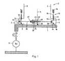
- schematisch einen axialen Schnitt durch eine erfindungsgemässe Werkstückträgereinrichtung gemäss einer ersten Ausführungsform,
- Fig. 2
- einen Ausschnitt aus
Fig. 1 , - Fig. 3
- eine Draufsicht auf den Ausschnitt gemäss
Fig. 2 , - Fig. 4
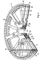
- teilweise geschnitten einen Teil der erfindungsgemässen Werkstückträgereinrichtung in perspektivischer Darstellung und
- Fig. 5
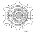
- vergrössert eine Draufsicht auf einen Teil der erfindungsgemässen Werkstückträgereinrichtung.
- Fig. 1
- FIG. 2 schematically a section through an inventive workpiece carrier device according to a first embodiment, FIG.
- Fig. 2
- a section from
Fig. 1 . - Fig. 3
- a plan view of the neck according to
Fig. 2 . - Fig. 4
- partially cut a part of the inventive workpiece carrier device in a perspective view and
- Fig. 5
- enlarges a plan view of a part of the inventive workpiece carrier device.
Gemäss einer bevorzugten Ausführungsform einer erfindungsgemässen Werkstückträgereinrichtung ist (
Das Drehgestell 3 trägt an jeder der besagten Auskragungen eine Gruppe 12 von Werkstückhaltern 13, die jeweils auf gleicher Höhe gleichmässig über einen die Antriebsachse 4 umgebenden Kreis verteilt sind. Jeder Werkstückhalter 13 ist um eine zur Antriebsachse 4 parallele Halterachse drehbar und umfasst eine Basis 14, die z.T. innerhalb einer Auskragung des Drehgestells 3 liegt und eine Halterung 15 zur Befestigung eines Werkstücks 16, welche mit der Basis 14 über einen durch den Deckel 10 durchgeführten Achsstift 17 verbunden ist. Weiter umfasst die Basis 14 einen Lagerstift 18 mit einer nach unten weisenden kegelförmigen Spitze, dessen Achse wie beim Achsstift 17 mit der Halterachse zusammenfällt und im Boden 9, wo die Spitze in eine entsprechende Ausnehmung eingreift, drehbar gelagert ist. Der Lagerstift 18 und der Achsstift 17 sind jeweils durch einen kurbelartigen Zwischenabschnitt verbunden, welcher einen zur Halterachse parallelen, aber von ihr beabstandeten Antriebsstift 19 umfasst. Die Basis 14 ist ein einfaches Biegeteil von im wesentlichen gleichbleibendem Querschnitt. Die aufgesteckte Halterung 15 weist eine oben offene zylindrische Ausnehmung auf, in welche das Werkstück 16, z.B. ein Fräskopf, eingesteckt ist.The
Eine am Grundgestell 1 drehfest verankerte Welle 20 trägt auf der Höhe jeder der Gruppen 12 ein gegenüber dem Grundgestell 1 unverdrehbares Zentralrad 21 (s. a.
Das Ritzel 25 ist mit den Antriebsstiften 19 der auf der Höhe des Zentralrades 21 und des Antriebsteils 22 liegenden Gruppe 12 von Werkstückträgern 13 durch ein Uebertragerteil 26 verbunden, das eine kreisförmige zentrale Kopplungsausnehmung aufweist. Ihr Rand trägt einen nach innen weisenden Zahnkranz 27, welcher mit der Verzahnung des Ritzels 25 eingreift. Weiter aussen weist das Uebertragerteil 26 für jeden Werkstückhalter 13 eine Antriebsöffnung 28 auf, durch welche dessen Antriebsstift 19, von ihrem Rand knapp umgeben, ragt. Das Uebertragerteil 26 ist also mit den Werkstückhaltern 13 jeweils drehbar, aber im übrigen mit geringem Spiel verbunden und steht mit dem Antriebsteil 22, genauer dem Ritzel 25 desselben, im Eingriff.The
Der Mittelpunkt des Zahnkranzes 27 am Uebertragerteil 26 bildet einen Abtriebspunkt 29, der von der Antriebsachse 4 um eine Exzentrizität E beabstandet ist. Der Abstand des Antriebsstiftes 19 eines jeden Werkstückhalters 13 von der jeweiligen Halterachse entspricht ebenfalls der Exzentrizität E.The center of the
Das Uebertragerteil 26, das in
Wird das Drehgestell 3 durch den Motor 6 um die Antriebsachse 4 gedreht, so wird über die mit dem Drehgestell 3 verbundenen Werkstückträger 13 das mit denselben eingreifende Uebertragerteil 26 mitgenommen. Da die Verzahnung des Ritzels 25 mit dem Zahnkranz 27 eingreift, wird dasselbe auch in Drehung versetzt und läuft auf dem Zentralrad 21 ab, wodurch das Antriebsteil 22 gegenüber dem Uebertragerteil 26 verdreht wird und eine Exzenterbewegung desselben bewirkt, bei welcher der die Drehachse 4 mit dem Abtriebspunkt 29 verbindende Vektor, dessen Länge der Exzentrizität E entspricht, um die Drehachse 4 umläuft. Die Exzenterbewegung überträgt sich auf die Antriebsstifte 19, sodass jeder Umlauf der Exzenterbewegung eine Umdrehung der Werkstückträger 13 bewirkt, wobei jeweils der von der Halterachse zum entsprechenden Antriebsstift 19 weisende Vektor jederzeit zum obengenannten Vektor parallel ist.If the
Betrachtet man die Bewegungen des Uebertragerteils 26 und des Antriebsteils 22 in einem am Grundgestell 1 festgemachten Koordinatensystem (s. dazu ![]()
![]()
Umdrehungen im Uhrzeigersinn. Mit z=Zz /ZU gilt also ![]()
![]()
Dies ergibt sich daraus, dass das Uebertragerteil 26 einerseits mitdreht, d.h. ebenfalls eine volle Umdrehung im Uhrzeigersinn ausführt und andererseits zusätzlich durch das auf dem Zentralrad 21 ablaufende Ritzel 25 um z Umdrehungen gedreht wird. Auf 1+z Umdrehungen des Drehgestells 3 kommt also eine Umdrehung des Antriebsteils 22. Damit ergibt sich für das Uebersetzungsverhältnis, d.h. den Quotienten zwischen der Drehrate des Antriebsteils 22 und damit der Exzenterbewegung des Uebertragerteils 26 einerseits und der Drehrate des Drehgestells 3 andererseits 
Gilt also z.B. wie beim Ausführungsbeispiel gemäss
Das Uebersetzungsverhältnis hängt nur von z ab und kann z.B. durch Auswechseln der Welle 20 mit den Zentralrädern 21 und den Antriebsteilen 22 leicht geändert werden. So kann etwa eine andere Welle mit kleineren Zentralrädern eingesetzt und damit z verkleinert und das Uebersetzungsverhältnis u entsprechend (2) vergrössert werden. Der Eingriff mit dem Zahnkranz des Uebertragerteils verlangt dann grössere Ritzel, welche aber das Uebersetzungsverhältnis u nicht beeinflussen. Falls nötig können zusätzlich die Uebertragerteile ausgewechselt werden, doch ist dies aufwendiger.The transmission ratio depends only on z and can be easily changed, for example, by replacing the
Es ist jedoch leicht möglich, statt eines Ritzels ein komplexeres Zwischengetriebe mit mehreren an der Halterung des Antriebsteils gelagerten, miteinander in Wirkverbindung stehenden Zahnrädern, von denen eines mit der Zentralverzahnung und eines mit der Uebertragerverzahnung eingreift, einzusetzen. Das Uebersetzungsverhältnis u kann für verschiedene Gruppen von Werkstückträgern auch unterschiedlich eingestellt werden, indem eine Welle mit unterschiedlichen Zwischengetrieben und/oder Zentralrädern verwendet wird.However, it is easily possible, instead of a pinion, a more complex intermediate gear with a plurality of mounted on the holder of the drive member, each operatively connected gears, one of which engages with the central teeth and one with the Uebertragerverzahnung. The gear ratio u can also be set differently for different groups of workpiece carriers by using a shaft with different intermediate gears and / or central gears.
Die Ausbildung des geschilderten Ausführungsbeispiels kann auch in anderer Weise abgewandelt werden, ohne dass das Gebiet der Erfindung verlassen würde. So braucht die Zentralverzahnung nicht drehfest mit dem Grundgestell verbunden sein. Es ist z.B. möglich, die die Zentralräder tragende Welle über ein von der Bewegung des Drehgestells angetriebenes Vorgelegegetriebe mit dem Grundgestell zu verbinden, sodass die Zentralverzahnung jeweils eine Drehbewegung ausführt. Ein solches Vorgelegegetriebe kann etwa wie in
- 11
- Grundgestellbase frame
- 22
- WerkstückträgerWorkpiece carrier
- 33
- Drehgestellbogie
- 44
- Antriebsachsedrive axle
- 55
- Zahnkranzsprocket
- 66
- Motorengine
- 77
- Zahnradgear
- 88th
- Rohrabschnittpipe section
- 99
- Bodenground
- 1010
- Deckelcover
- 1111
- Aussenringthe outer ring
- 1212
- Gruppegroup
- 1313
- WerkstückhalterWorkpiece holder
- 1414
- BasisBase
- 1515
- Halterungbracket
- 1616
- Werkstückworkpiece
- 1717
- Achsstiftaxle pin
- 1818
- Lagerstiftbearing pin
- 1919
- Antriebsstiftdrive pin
- 2020
- Wellewave
- 2121
- Zentralradcentral wheel
- 2222
- Antriebsteildriving part
- 2323
- oberer Armupper arm
- 2424
- unterer Armlower arm
- 2525
- Ritzelpinion
- 2626
- Uebertragerteiltransmission part
- 2727
- Zahnkranzsprocket
- 2828
- Antriebsöffnungdrive opening
- 2929
- Abtriebspunktoutput point
- 3030
- Innenringinner ring
- 3131
- Aussenringthe outer ring
- 3232
- Speichespoke
- 3333
- Lochhole
Claims (2)
- Workpiece carrier device having at least one workpiece carrier (2), with a shaft (20) surrounding a driving axis (4) and a rotary frame (3) mounted on a base frame (1) so as to be rotatable about the driving axis (4), and with workpiece holders (13) mounted on the rotary frame (3) so as to be rotatable about holding axes, wherein the at least one workpiece carrier (2) comprises a driving part (22) with a holder mounted so as to be rotatable about the driving axis (4), as well as a transmission part (26) operationally connected to the rotatably mounted workpiece holders (13), characterised in that an intermediate gear is attached to the rotatably mounted holder, the intermediate gear being operationally connected to the shaft (20) and the transmission part (26), respectively, in such a way that the transmission part (26) engages with the driving part (22) so as to be rotatable about an output point (29) that is spaced apart from the driving axis (4) by an eccentricity (E).
- Workpiece carrier device according to claim 1, characterised in that, for the purpose of rotating the workpiece holders (13) with respect to the rotary frame (3), the transmission part (26) further engages with at least two workpiece holders (13) so as to be rotatable about a driving point that is spaced apart from the holder axis by the same eccentricity (E).
Priority Applications (2)
| Application Number | Priority Date | Filing Date | Title |
|---|---|---|---|
| EP11405237.6A EP2336387B1 (en) | 2007-10-08 | 2007-10-08 | Workpiece mount device |
| PL11405237T PL2336387T3 (en) | 2007-10-08 | 2007-10-08 | Workpiece mount device |
Applications Claiming Priority (2)
| Application Number | Priority Date | Filing Date | Title |
|---|---|---|---|
| EP07405302A EP2048263B1 (en) | 2007-10-08 | 2007-10-08 | Workpiece mount device |
| EP11405237.6A EP2336387B1 (en) | 2007-10-08 | 2007-10-08 | Workpiece mount device |
Related Parent Applications (1)
| Application Number | Title | Priority Date | Filing Date |
|---|---|---|---|
| EP07405302.6 Division | 2007-10-08 |
Publications (2)
| Publication Number | Publication Date |
|---|---|
| EP2336387A1 EP2336387A1 (en) | 2011-06-22 |
| EP2336387B1 true EP2336387B1 (en) | 2013-09-04 |
Family
ID=38982780
Family Applications (2)
| Application Number | Title | Priority Date | Filing Date |
|---|---|---|---|
| EP11405237.6A Active EP2336387B1 (en) | 2007-10-08 | 2007-10-08 | Workpiece mount device |
| EP07405302A Not-in-force EP2048263B1 (en) | 2007-10-08 | 2007-10-08 | Workpiece mount device |
Family Applications After (1)
| Application Number | Title | Priority Date | Filing Date |
|---|---|---|---|
| EP07405302A Not-in-force EP2048263B1 (en) | 2007-10-08 | 2007-10-08 | Workpiece mount device |
Country Status (14)
| Country | Link |
|---|---|
| US (2) | US8596626B2 (en) |
| EP (2) | EP2336387B1 (en) |
| JP (1) | JP5497647B2 (en) |
| KR (1) | KR20100071057A (en) |
| CN (1) | CN101827955B (en) |
| AT (1) | ATE503858T1 (en) |
| BR (1) | BRPI0818592A2 (en) |
| DE (1) | DE502007006849D1 (en) |
| ES (1) | ES2362016T3 (en) |
| MX (1) | MX2010003727A (en) |
| PL (2) | PL2336387T3 (en) |
| RU (1) | RU2485211C2 (en) |
| TW (1) | TWI481448B (en) |
| WO (1) | WO2009046928A1 (en) |
Families Citing this family (13)
| Publication number | Priority date | Publication date | Assignee | Title |
|---|---|---|---|---|
| EP2336387B1 (en) * | 2007-10-08 | 2013-09-04 | Oerlikon Trading AG, Trübbach | Workpiece mount device |
| DE102010001218A1 (en) | 2010-01-26 | 2011-07-28 | Esser, Stefan, Dr.-Ing., 52072 | Substrate plate and coating system for coating substrates |
| SG184626A1 (en) * | 2011-03-17 | 2012-10-30 | Sulzer Metco Ag | Component manipulator for the dynamic positioning of a substrate, coating method, as well as use of a component manipulator |
| CA2858188C (en) | 2011-12-08 | 2018-03-06 | Praxair S.T. Technology, Inc. | Multifunction tooling fixture assembly for use in a coating related operations |
| RU2625698C1 (en) * | 2016-08-29 | 2017-07-18 | Федеральное государственное унитарное предприятие "Всероссийский научно-исследовательский институт авиационных материалов" (ФГУП "ВИАМ") | Method of application of protective coatings and device for its implementation |
| CN107740063B (en) * | 2017-11-16 | 2024-07-23 | 东莞市赢心科技有限公司 | Workpiece bearing structure for vacuum aluminizing equipment |
| KR101869401B1 (en) * | 2018-01-04 | 2018-07-20 | 홍성신 | A apparatus of changing work of the precision lathe |
| RU2688353C1 (en) * | 2018-08-09 | 2019-05-21 | Российская Федерация, от имени которой выступает Государственная корпорация по атомной энергии "Росатом" (Госкорпорация "Росатом") | Apparatus for movement and rotation of substrate holder |
| DE102018126862A1 (en) | 2018-10-26 | 2020-04-30 | Oerlikon Surface Solutions Ag, Pfäffikon | Workpiece carrier device and coating arrangement |
| DE102019110158A1 (en) | 2019-04-17 | 2020-10-22 | Oerlikon Surface Solutions Ag, Pfäffikon | WORKPIECE CARRIER |
| US12024769B2 (en) | 2019-05-07 | 2024-07-02 | Oerlikon Surface Solutions Ag, Pfäffikon | Movable work piece carrier device for holding work pieces to be treated |
| FI4004253T3 (en) | 2019-07-26 | 2024-03-14 | Oerlikon Surface Solutions Ag Pfaeffikon | Fixture to be used in pvd processes for cylindrical, elongated substrates |
| CN114271649B (en) * | 2021-12-27 | 2022-11-25 | 西南民族大学 | Artwork display equipment |
Family Cites Families (11)
| Publication number | Priority date | Publication date | Assignee | Title |
|---|---|---|---|---|
| SU370279A1 (en) * | 1969-08-21 | 1973-02-15 | DEVICE FOR TRANSPORTATION AND CHANGE OF SUBSTRATES IN VACUUM INSTALLATIONS | |
| JPH01288652A (en) * | 1988-05-17 | 1989-11-20 | Komatsu Ltd | Reduction gear |
| SU1828669A3 (en) * | 1990-11-13 | 1995-05-27 | Владимир Васильевич Кульпинов | Apparatus to treat peaces in vacuum |
| DE19803278C2 (en) | 1998-01-29 | 2001-02-01 | Bosch Gmbh Robert | Workpiece carrier and its use for the treatment and coating of workpieces |
| DE59911507D1 (en) | 1998-12-15 | 2005-02-24 | Balzers Hochvakuum | PLANET SYSTEM-WORKPIECE CARRIER AND METHOD FOR SURFACE TREATMENT OF WORKPIECES |
| US6749764B1 (en) * | 2000-11-14 | 2004-06-15 | Tru-Si Technologies, Inc. | Plasma processing comprising three rotational motions of an article being processed |
| DE10308471B4 (en) | 2003-02-20 | 2005-03-24 | Hensoldt Ag | Coating plant for coating substrates for optical components |
| CN1865495A (en) * | 2005-05-20 | 2006-11-22 | 中国科学院半导体研究所 | Revolution and rotation arrangement in reaction chamber of metallorganics chemical vapor deposition device |
| CN101253281B (en) * | 2005-08-29 | 2010-12-08 | 奥尔利康贸易股份公司(特吕巴赫) | Workpiece Carrier |
| US7988787B2 (en) * | 2007-08-27 | 2011-08-02 | Caterpillar Inc. | Workpiece support system and method |
| EP2336387B1 (en) * | 2007-10-08 | 2013-09-04 | Oerlikon Trading AG, Trübbach | Workpiece mount device |
-
2007
- 2007-10-08 EP EP11405237.6A patent/EP2336387B1/en active Active
- 2007-10-08 ES ES07405302T patent/ES2362016T3/en active Active
- 2007-10-08 PL PL11405237T patent/PL2336387T3/en unknown
- 2007-10-08 AT AT07405302T patent/ATE503858T1/en active
- 2007-10-08 PL PL07405302T patent/PL2048263T3/en unknown
- 2007-10-08 EP EP07405302A patent/EP2048263B1/en not_active Not-in-force
- 2007-10-08 DE DE502007006849T patent/DE502007006849D1/en active Active
-
2008
- 2008-10-02 MX MX2010003727A patent/MX2010003727A/en active IP Right Grant
- 2008-10-02 KR KR1020107007588A patent/KR20100071057A/en not_active Application Discontinuation
- 2008-10-02 BR BRPI0818592A patent/BRPI0818592A2/en not_active IP Right Cessation
- 2008-10-02 CN CN2008801106260A patent/CN101827955B/en active Active
- 2008-10-02 RU RU2010113596/02A patent/RU2485211C2/en not_active IP Right Cessation
- 2008-10-02 WO PCT/EP2008/008349 patent/WO2009046928A1/en active Application Filing
- 2008-10-02 JP JP2010528299A patent/JP5497647B2/en active Active
- 2008-10-02 US US12/681,833 patent/US8596626B2/en active Active
- 2008-10-06 TW TW097138355A patent/TWI481448B/en not_active IP Right Cessation
-
2013
- 2013-09-04 US US14/018,118 patent/US8783673B2/en active Active
Also Published As
| Publication number | Publication date |
|---|---|
| WO2009046928A1 (en) | 2009-04-16 |
| JP2011502211A (en) | 2011-01-20 |
| EP2048263A1 (en) | 2009-04-15 |
| US8596626B2 (en) | 2013-12-03 |
| PL2048263T3 (en) | 2011-09-30 |
| RU2010113596A (en) | 2011-11-20 |
| DE502007006849D1 (en) | 2011-05-12 |
| US20140008857A1 (en) | 2014-01-09 |
| PL2336387T3 (en) | 2014-01-31 |
| US20100270722A1 (en) | 2010-10-28 |
| BRPI0818592A2 (en) | 2017-06-13 |
| ATE503858T1 (en) | 2011-04-15 |
| MX2010003727A (en) | 2010-04-21 |
| JP5497647B2 (en) | 2014-05-21 |
| CN101827955A (en) | 2010-09-08 |
| US8783673B2 (en) | 2014-07-22 |
| EP2336387A1 (en) | 2011-06-22 |
| ES2362016T3 (en) | 2011-06-27 |
| TWI481448B (en) | 2015-04-21 |
| CN101827955B (en) | 2012-11-07 |
| TW200936249A (en) | 2009-09-01 |
| EP2048263B1 (en) | 2011-03-30 |
| KR20100071057A (en) | 2010-06-28 |
| RU2485211C2 (en) | 2013-06-20 |
Similar Documents
| Publication | Publication Date | Title |
|---|---|---|
| EP2336387B1 (en) | Workpiece mount device | |
| EP1917380B9 (en) | Workpiece support system | |
| EP2287053B1 (en) | Device for cleaning vehicle wheels | |
| DE69108688T2 (en) | Differential gear unit with floating ring gear. | |
| EP1926624B1 (en) | Drive system for the individual drive of both driven wheels of a driven wheel pair | |
| DE3242541C2 (en) | ||
| EP2565495B1 (en) | Dispositif d'engrenage avec colonnette de soutien pour un véhicule | |
| DE102009042834A1 (en) | Drive shaft assembly for a transmission of a motor vehicle | |
| DE102007035010A1 (en) | Steering unit for wheel of industrial truck, has roller bearing of pivot plate arranged within steering gear i.e. multi-stage spur gear, or steering gear provided partially within roller bearing, and coaxial pin connected with center plate | |
| EP0575858B1 (en) | Centrifuge | |
| EP1769174B1 (en) | Differential for a vehicle axle | |
| DE102014005435A1 (en) | Exzenteroszillationsgetriebevorrichtung | |
| EP3323717B1 (en) | Rotor mast | |
| DE102019203152A1 (en) | TRANSMISSION DEVICE | |
| DE10253465A1 (en) | Steering system for a vehicle | |
| EP2066925B1 (en) | Multi-stage reduction gear | |
| EP2092217A1 (en) | Device for optimizing the feed function of the ring gear of a differential with regard to maximum volume flow rate | |
| DE2926598C2 (en) | ||
| EP2024545B1 (en) | Improved thread unwinding device | |
| EP0248289A2 (en) | Toothed gearing with a continuously variable transmission ratio | |
| DE102008051502B4 (en) | Drive device for an automatic tool changer | |
| CH698143B1 (en) | Workpiece carrier device. | |
| DE10234770B3 (en) | Device for producing hollow molds from food masses | |
| WO1999004184A1 (en) | Return planetary gear system | |
| DE3643613A1 (en) | AXIAL DRIVE |
Legal Events
| Date | Code | Title | Description |
|---|---|---|---|
| PUAI | Public reference made under article 153(3) epc to a published international application that has entered the european phase |
Free format text: ORIGINAL CODE: 0009012 |
|
| AC | Divisional application: reference to earlier application |
Ref document number: 2048263 Country of ref document: EP Kind code of ref document: P |
|
| AK | Designated contracting states |
Kind code of ref document: A1 Designated state(s): AT BE BG CH CY CZ DE DK EE ES FI FR GB GR HU IE IS IT LI LT LU LV MC MT NL PL PT RO SE SI SK TR |
|
| 17P | Request for examination filed |
Effective date: 20111102 |
|
| 17Q | First examination report despatched |
Effective date: 20120315 |
|
| GRAP | Despatch of communication of intention to grant a patent |
Free format text: ORIGINAL CODE: EPIDOSNIGR1 |
|
| RIC1 | Information provided on ipc code assigned before grant |
Ipc: C23C 14/50 20060101AFI20130307BHEP Ipc: C23C 16/458 20060101ALI20130307BHEP Ipc: F16H 21/14 20060101ALN20130307BHEP |
|
| INTG | Intention to grant announced |
Effective date: 20130326 |
|
| GRAS | Grant fee paid |
Free format text: ORIGINAL CODE: EPIDOSNIGR3 |
|
| GRAA | (expected) grant |
Free format text: ORIGINAL CODE: 0009210 |
|
| AC | Divisional application: reference to earlier application |
Ref document number: 2048263 Country of ref document: EP Kind code of ref document: P |
|
| AK | Designated contracting states |
Kind code of ref document: B1 Designated state(s): AT BE BG CH CY CZ DE DK EE ES FI FR GB GR HU IE IS IT LI LT LU LV MC MT NL PL PT RO SE SI SK TR |
|
| REG | Reference to a national code |
Ref country code: GB Ref legal event code: FG4D Free format text: NOT ENGLISH |
|
| REG | Reference to a national code |
Ref country code: CH Ref legal event code: EP |
|
| REG | Reference to a national code |
Ref country code: AT Ref legal event code: REF Ref document number: 630602 Country of ref document: AT Kind code of ref document: T Effective date: 20130915 |
|
| REG | Reference to a national code |
Ref country code: IE Ref legal event code: FG4D Free format text: LANGUAGE OF EP DOCUMENT: GERMAN |
|
| REG | Reference to a national code |
Ref country code: DE Ref legal event code: R096 Ref document number: 502007012248 Country of ref document: DE Effective date: 20131031 |
|
| REG | Reference to a national code |
Ref country code: NL Ref legal event code: T3 |
|
| REG | Reference to a national code |
Ref country code: SE Ref legal event code: TRGR |
|
| PG25 | Lapsed in a contracting state [announced via postgrant information from national office to epo] |
Ref country code: CY Free format text: LAPSE BECAUSE OF FAILURE TO SUBMIT A TRANSLATION OF THE DESCRIPTION OR TO PAY THE FEE WITHIN THE PRESCRIBED TIME-LIMIT Effective date: 20130724 Ref country code: LT Free format text: LAPSE BECAUSE OF FAILURE TO SUBMIT A TRANSLATION OF THE DESCRIPTION OR TO PAY THE FEE WITHIN THE PRESCRIBED TIME-LIMIT Effective date: 20130904 |
|
| REG | Reference to a national code |
Ref country code: PL Ref legal event code: T3 |
|
| REG | Reference to a national code |
Ref country code: LT Ref legal event code: MG4D |
|
| PG25 | Lapsed in a contracting state [announced via postgrant information from national office to epo] |
Ref country code: GR Free format text: LAPSE BECAUSE OF FAILURE TO SUBMIT A TRANSLATION OF THE DESCRIPTION OR TO PAY THE FEE WITHIN THE PRESCRIBED TIME-LIMIT Effective date: 20131205 Ref country code: FI Free format text: LAPSE BECAUSE OF FAILURE TO SUBMIT A TRANSLATION OF THE DESCRIPTION OR TO PAY THE FEE WITHIN THE PRESCRIBED TIME-LIMIT Effective date: 20130904 Ref country code: SI Free format text: LAPSE BECAUSE OF FAILURE TO SUBMIT A TRANSLATION OF THE DESCRIPTION OR TO PAY THE FEE WITHIN THE PRESCRIBED TIME-LIMIT Effective date: 20130904 Ref country code: LV Free format text: LAPSE BECAUSE OF FAILURE TO SUBMIT A TRANSLATION OF THE DESCRIPTION OR TO PAY THE FEE WITHIN THE PRESCRIBED TIME-LIMIT Effective date: 20130904 |
|
| REG | Reference to a national code |
Ref country code: SK Ref legal event code: T3 Ref document number: E 15331 Country of ref document: SK |
|
| PG25 | Lapsed in a contracting state [announced via postgrant information from national office to epo] |
Ref country code: CY Free format text: LAPSE BECAUSE OF FAILURE TO SUBMIT A TRANSLATION OF THE DESCRIPTION OR TO PAY THE FEE WITHIN THE PRESCRIBED TIME-LIMIT Effective date: 20130904 |
|
| PG25 | Lapsed in a contracting state [announced via postgrant information from national office to epo] |
Ref country code: RO Free format text: LAPSE BECAUSE OF FAILURE TO SUBMIT A TRANSLATION OF THE DESCRIPTION OR TO PAY THE FEE WITHIN THE PRESCRIBED TIME-LIMIT Effective date: 20130904 Ref country code: EE Free format text: LAPSE BECAUSE OF FAILURE TO SUBMIT A TRANSLATION OF THE DESCRIPTION OR TO PAY THE FEE WITHIN THE PRESCRIBED TIME-LIMIT Effective date: 20130904 Ref country code: IS Free format text: LAPSE BECAUSE OF FAILURE TO SUBMIT A TRANSLATION OF THE DESCRIPTION OR TO PAY THE FEE WITHIN THE PRESCRIBED TIME-LIMIT Effective date: 20140104 |
|
| PG25 | Lapsed in a contracting state [announced via postgrant information from national office to epo] |
Ref country code: ES Free format text: LAPSE BECAUSE OF FAILURE TO SUBMIT A TRANSLATION OF THE DESCRIPTION OR TO PAY THE FEE WITHIN THE PRESCRIBED TIME-LIMIT Effective date: 20130904 |
|
| REG | Reference to a national code |
Ref country code: DE Ref legal event code: R097 Ref document number: 502007012248 Country of ref document: DE |
|
| PG25 | Lapsed in a contracting state [announced via postgrant information from national office to epo] |
Ref country code: PT Free format text: LAPSE BECAUSE OF FAILURE TO SUBMIT A TRANSLATION OF THE DESCRIPTION OR TO PAY THE FEE WITHIN THE PRESCRIBED TIME-LIMIT Effective date: 20140106 Ref country code: MC Free format text: LAPSE BECAUSE OF FAILURE TO SUBMIT A TRANSLATION OF THE DESCRIPTION OR TO PAY THE FEE WITHIN THE PRESCRIBED TIME-LIMIT Effective date: 20130904 |
|
| PLBE | No opposition filed within time limit |
Free format text: ORIGINAL CODE: 0009261 |
|
| STAA | Information on the status of an ep patent application or granted ep patent |
Free format text: STATUS: NO OPPOSITION FILED WITHIN TIME LIMIT |
|
| REG | Reference to a national code |
Ref country code: IE Ref legal event code: MM4A |
|
| 26N | No opposition filed |
Effective date: 20140605 |
|
| REG | Reference to a national code |
Ref country code: DE Ref legal event code: R097 Ref document number: 502007012248 Country of ref document: DE Effective date: 20140605 |
|
| REG | Reference to a national code |
Ref country code: HU Ref legal event code: AG4A Ref document number: E020309 Country of ref document: HU |
|
| PG25 | Lapsed in a contracting state [announced via postgrant information from national office to epo] |
Ref country code: DK Free format text: LAPSE BECAUSE OF FAILURE TO SUBMIT A TRANSLATION OF THE DESCRIPTION OR TO PAY THE FEE WITHIN THE PRESCRIBED TIME-LIMIT Effective date: 20130904 |
|
| PG25 | Lapsed in a contracting state [announced via postgrant information from national office to epo] |
Ref country code: IE Free format text: LAPSE BECAUSE OF NON-PAYMENT OF DUE FEES Effective date: 20131008 |
|
| PGFP | Annual fee paid to national office [announced via postgrant information from national office to epo] |
Ref country code: TR Payment date: 20140918 Year of fee payment: 8 Ref country code: SK Payment date: 20140905 Year of fee payment: 8 Ref country code: PL Payment date: 20140916 Year of fee payment: 8 Ref country code: LU Payment date: 20141013 Year of fee payment: 8 |
|
| PGFP | Annual fee paid to national office [announced via postgrant information from national office to epo] |
Ref country code: CZ Payment date: 20141003 Year of fee payment: 8 Ref country code: FR Payment date: 20141008 Year of fee payment: 8 Ref country code: SE Payment date: 20141013 Year of fee payment: 8 Ref country code: GB Payment date: 20141008 Year of fee payment: 8 |
|
| PGFP | Annual fee paid to national office [announced via postgrant information from national office to epo] |
Ref country code: HU Payment date: 20140923 Year of fee payment: 8 Ref country code: NL Payment date: 20141010 Year of fee payment: 8 Ref country code: AT Payment date: 20140925 Year of fee payment: 8 |
|
| PGFP | Annual fee paid to national office [announced via postgrant information from national office to epo] |
Ref country code: IT Payment date: 20141021 Year of fee payment: 8 |
|
| PGFP | Annual fee paid to national office [announced via postgrant information from national office to epo] |
Ref country code: CH Payment date: 20150127 Year of fee payment: 8 Ref country code: BE Payment date: 20141013 Year of fee payment: 8 |
|
| PG25 | Lapsed in a contracting state [announced via postgrant information from national office to epo] |
Ref country code: BG Free format text: LAPSE BECAUSE OF FAILURE TO SUBMIT A TRANSLATION OF THE DESCRIPTION OR TO PAY THE FEE WITHIN THE PRESCRIBED TIME-LIMIT Effective date: 20130904 |
|
| PG25 | Lapsed in a contracting state [announced via postgrant information from national office to epo] |
Ref country code: MT Free format text: LAPSE BECAUSE OF FAILURE TO SUBMIT A TRANSLATION OF THE DESCRIPTION OR TO PAY THE FEE WITHIN THE PRESCRIBED TIME-LIMIT Effective date: 20130904 |
|
| PG25 | Lapsed in a contracting state [announced via postgrant information from national office to epo] |
Ref country code: CZ Free format text: LAPSE BECAUSE OF NON-PAYMENT OF DUE FEES Effective date: 20151008 |
|
| PG25 | Lapsed in a contracting state [announced via postgrant information from national office to epo] |
Ref country code: LU Free format text: LAPSE BECAUSE OF NON-PAYMENT OF DUE FEES Effective date: 20151008 |
|
| REG | Reference to a national code |
Ref country code: SE Ref legal event code: EUG Ref country code: CH Ref legal event code: PL |
|
| REG | Reference to a national code |
Ref country code: AT Ref legal event code: MM01 Ref document number: 630602 Country of ref document: AT Kind code of ref document: T Effective date: 20151008 |
|
| GBPC | Gb: european patent ceased through non-payment of renewal fee |
Effective date: 20151008 |
|
| REG | Reference to a national code |
Ref country code: SK Ref legal event code: MM4A Ref document number: E 15331 Country of ref document: SK Effective date: 20151008 |
|
| REG | Reference to a national code |
Ref country code: NL Ref legal event code: MM Effective date: 20151101 |
|
| PG25 | Lapsed in a contracting state [announced via postgrant information from national office to epo] |
Ref country code: LI Free format text: LAPSE BECAUSE OF NON-PAYMENT OF DUE FEES Effective date: 20151031 Ref country code: IT Free format text: LAPSE BECAUSE OF NON-PAYMENT OF DUE FEES Effective date: 20151008 Ref country code: GB Free format text: LAPSE BECAUSE OF NON-PAYMENT OF DUE FEES Effective date: 20151008 Ref country code: CH Free format text: LAPSE BECAUSE OF NON-PAYMENT OF DUE FEES Effective date: 20151031 |
|
| REG | Reference to a national code |
Ref country code: FR Ref legal event code: ST Effective date: 20160630 |
|
| PG25 | Lapsed in a contracting state [announced via postgrant information from national office to epo] |
Ref country code: SE Free format text: LAPSE BECAUSE OF NON-PAYMENT OF DUE FEES Effective date: 20151009 Ref country code: SK Free format text: LAPSE BECAUSE OF NON-PAYMENT OF DUE FEES Effective date: 20151008 Ref country code: FR Free format text: LAPSE BECAUSE OF NON-PAYMENT OF DUE FEES Effective date: 20151102 Ref country code: AT Free format text: LAPSE BECAUSE OF NON-PAYMENT OF DUE FEES Effective date: 20151008 Ref country code: HU Free format text: LAPSE BECAUSE OF NON-PAYMENT OF DUE FEES Effective date: 20151009 Ref country code: NL Free format text: LAPSE BECAUSE OF NON-PAYMENT OF DUE FEES Effective date: 20151101 |
|
| PG25 | Lapsed in a contracting state [announced via postgrant information from national office to epo] |
Ref country code: PL Free format text: LAPSE BECAUSE OF NON-PAYMENT OF DUE FEES Effective date: 20151008 |
|
| PG25 | Lapsed in a contracting state [announced via postgrant information from national office to epo] |
Ref country code: BE Free format text: LAPSE BECAUSE OF NON-PAYMENT OF DUE FEES Effective date: 20151031 |
|
| PG25 | Lapsed in a contracting state [announced via postgrant information from national office to epo] |
Ref country code: TR Free format text: LAPSE BECAUSE OF NON-PAYMENT OF DUE FEES Effective date: 20151008 |
|
| PGFP | Annual fee paid to national office [announced via postgrant information from national office to epo] |
Ref country code: DE Payment date: 20241029 Year of fee payment: 18 |