EP2336007A1 - Side sill assembly for a vehicle body and method for producing the same - Google Patents
Side sill assembly for a vehicle body and method for producing the same Download PDFInfo
- Publication number
- EP2336007A1 EP2336007A1 EP10007138A EP10007138A EP2336007A1 EP 2336007 A1 EP2336007 A1 EP 2336007A1 EP 10007138 A EP10007138 A EP 10007138A EP 10007138 A EP10007138 A EP 10007138A EP 2336007 A1 EP2336007 A1 EP 2336007A1
- Authority
- EP
- European Patent Office
- Prior art keywords
- sill
- connection
- steel
- aluminum
- side part
- Prior art date
- Legal status (The legal status is an assumption and is not a legal conclusion. Google has not performed a legal analysis and makes no representation as to the accuracy of the status listed.)
- Granted
Links
Images

Classifications
-
- B—PERFORMING OPERATIONS; TRANSPORTING
- B62—LAND VEHICLES FOR TRAVELLING OTHERWISE THAN ON RAILS
- B62D—MOTOR VEHICLES; TRAILERS
- B62D25/00—Superstructure or monocoque structure sub-units; Parts or details thereof not otherwise provided for
- B62D25/02—Side panels
- B62D25/025—Side sills thereof
-
- B—PERFORMING OPERATIONS; TRANSPORTING
- B62—LAND VEHICLES FOR TRAVELLING OTHERWISE THAN ON RAILS
- B62D—MOTOR VEHICLES; TRAILERS
- B62D21/00—Understructures, i.e. chassis frame on which a vehicle body may be mounted
- B62D21/15—Understructures, i.e. chassis frame on which a vehicle body may be mounted having impact absorbing means, e.g. a frame designed to permanently or temporarily change shape or dimension upon impact with another body
- B62D21/157—Understructures, i.e. chassis frame on which a vehicle body may be mounted having impact absorbing means, e.g. a frame designed to permanently or temporarily change shape or dimension upon impact with another body for side impacts
-
- B—PERFORMING OPERATIONS; TRANSPORTING
- B62—LAND VEHICLES FOR TRAVELLING OTHERWISE THAN ON RAILS
- B62D—MOTOR VEHICLES; TRAILERS
- B62D29/00—Superstructures, understructures, or sub-units thereof, characterised by the material thereof
- B62D29/008—Superstructures, understructures, or sub-units thereof, characterised by the material thereof predominantly of light alloys, e.g. extruded
Definitions
- the invention relates to a sill subassembly for a vehicle body according to the preamble of claim 1 and to a method for producing a sill subassembly for a vehicle body according to the preamble of claim 11.
- Such a sill assembly for a self-supporting body of a vehicle is well known.
- a Schwellerbauffle is below the door entry, on both sides of the vehicle, between the front and rear wheel arches.
- the sill has an essential role to play in absorbing forces, for example in a head-on collision.
- the sill is regularly no separate component and is composed of a side part, a reinforcement part and a sill inner part, which form a hollow profile. At the Schwellerinnenteil is regularly joined a floor panel.
- Such a sill is for example from the DE 10 2008 020 081 A1 known, in which the sill is formed as a cavity and having an inner panel and an outer panel and a reinforcing sheet.
- the outer panel and the inner panel is respectively connected on opposite sides to an upper flange portion of the reinforcing sheet.
- the reinforcing sheet is here strongly curved in the outward direction and forms approximately in a central region of the bulge, where the bulge maximum is reached, a connection area for a lower flange portion of the outer panel.
- the reinforcing profile is here further fastened on a sill shutter designed as an aluminum extruded profile.
- a sill of a motor vehicle with a reinforcing insert is also from the DE 197 08 215 C2 known.
- an elongated extruded profile part made of light metal is specifically provided, are connected to the node elements that can be connected to adjacent body parts.
- this provides a reinforced sill, which can be used in particular for use in a mixed construction with a material mix of light metal and adjacent sheet steel body parts use.
- a sill assembly for a vehicle body which has a sill inner part, a sill reinforcement part and a sill side part as a closing part, which together form a rocker hollow profile.
- the sill side part viewed in cross section, with a first connection region in the region of the sill assembly, set directly at the sill inner part, while between the sill reinforcement part and the sill side part, which are made of different materials or materials, a sill connection part is arranged as a separate component, which is firmly connected to the sill reinforcement part and to a second connection region of the sill side part, wherein it is preferably provided that the sill connection part is made of the same material as the sill reinforcement part or the sill side part.
- sill side part for example, from a light metal, in particular an aluminum, as will be explained in more detail below using the example of an aluminum sill inner part, is used.
- side parts made of a light metal with a very simple and thus manufacturing technology or drawing technology easy to produce geometry.
- the sill side part can be defined with its other connection area, which is not set on the sill connection part, to a variety of components of the sill assembly, so for example in a preferred embodiment directly and directly on the sill inner part, although the connection to the sill reinforcement part or any other additional component of Threshold assembly is also possible in principle.
- an aluminum sill joint part made of aluminum is arranged, which with the steel sill reinforcement part is connected by means of an adhesive and / or rivet and which is connected to the aluminum sill side part also by means of an adhesive and / or rivet or even by hot-joining, in particular laser welding.
- the abutting flange areas can be significantly shortened compared to a flange design for an adhesive and / or riveted joint.
- all components are preferably formed by sheets.
- both the sill reinforcement part and the sill connection part are made of a light metal, here aluminum, for example
- a particularly weight-optimized sill assembly can be realized, wherein moreover by the laser welding connection or an adhesive and riveted connection between the aluminum Sill side part and the aluminum sill connection part on the one hand and an adhesive and rivet connection between the steel sill reinforcement part and the aluminum connection part a sufficient cavity sealing of the hollow profile is achieved and thus an advantageous corrosion protection is achieved in this particularly splash-sensitive Schweller Symposium Symposium
- the rivet connection is formed by a plurality of individual, spaced-apart rivet points, which are preferably produced by solid punch rivets, resulting in a particularly intimate and firm connection between the components to be joined together. Basically, however, the use of semi-hollow punch rivets is possible.
- the steel sill reinforcement part is made of a preferably cold-formed steel and connected by means of a hot joining, in particular by means of a welded connection with the hot steel sill inner part made of a thermoformed steel.
- a hot joining in particular by means of a welded connection with the hot steel sill inner part made of a thermoformed steel.
- this connection takes place by means of an adhesive and / or riveted joint.
- the high-strength rivet connection may also be replaced by a screw connection.
- cold-formed and hot-formed steel is intended to express that these are different steel materials or materials, which differ in particular in that the hot-formed steel has a higher strength than the cold-formed steel.
- Particularly preferred here is a structure in which a steel bottom plate in vehicle vertical axis direction seen above an aluminum bottom wall in connection region of the steel sill reinforcement part so, preferably flat, is connected to the hot steel sill inner part, that the steel sill reinforcement part and the steel bottom support means of the same Welded connection are fixed to the high-pressure steel inner part of the sill.
- the sill inner part may, viewed in cross-section, preferably have a in the mounted state of the sill reinforcement connection area upwards in the vehicle vertical axis direction down and the sill inner part upwardly projecting sill side part connection area to which the sill side part is then connected, preferably in one flat system connection is connected adjacent, resulting in a particularly stable and high-quality and high-strength connection of the side sill part on the inner part of the sill.
- sill side member connection portion is formed bent towards the sill side part, and although preferably so bent is formed that adjoins an approximately extending in the vehicle transverse direction of the first section an angled and approximately vehicle vertical axis extending flange portion on which the rocker side member abuts in a flat contact connection and is connected there.
- the sill connection part itself has, viewed in cross-section, preferably an approximately U-shaped geometry with two spaced opposite, preferably substantially parallel aligned, U-legs, which may have the same as well as a different length.
- U-legs In conjunction with such U-legs is ensured in a simple manner that the sill side part and the sill connection part in each case in a planar abutment connection to the U-legs, in particular on the opposite sides Schenkelau builtores, abut and be connected there. This makes it possible to produce a high-strength connection between the individual components, in particular in conjunction with a desired tightness in this area in a simple and functionally reliable manner.
- the sill side part viewed in cross-section, extending substantially in the vehicle vertical axis direction of elongation direction, but also preferably in a central region between the two side member connecting portion-side outwardly directed away from the sill inner portion bulge may be provided to form a corresponding threshold volume ,
- the aluminum sill fastener member is first adhered and / or riveted to the steel sill reinforcement member, preferably for corrosion protection reasons glued and riveted there.
- This prefabricated assembly is then preferably welded to the hot steel inner part.
- the connection of a steel bottom support on the high-pressure steel inner edge part take place at the same time, in particular when the same welded joint is used for fixing the sill reinforcement part.
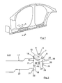
- a side section of a vehicle body 1 is shown having a Schwellerbauffle 2 according to the invention, which extends here seen in the vehicle longitudinal axis direction between an A-pillar 3 and a C-pillar 4.
- the basic structure of this Schwellerbauffle is basically the same in the area mentioned, also in the area of the connection of the A-pillar 3, a B-pillar 5 and a C-pillar 4 and is below with reference to the sectional view along the line AA Fig. 1 in conjunction with the Fig. 2 explained in more detail.
- the Fig. 2 shows a Schwellerbauffle 2 with an aluminum rocker side plate 6 as a sill side part, which is connected with a vehicle in the vertical axis direction seen upper flange first connection region 7 in a planar contact connection to a likewise approximately in the vehicle vertical axis extending flange portion 8 by means of a rivet connection 9.
- the rivet connection 9 is here preferably representative of a plurality of individual rivet connections, which are made for example by solid rivets. If this should be necessary for reasons of tightness or for reasons of strength, the flange section 8 and the first connection region 7 of the aluminum sill side plate 6 can also be additionally glued together by means of an adhesive connection, not shown here.
- the flange portion 8 is part of a hot steel sill inner panel 10 as a sill inner part, which has a flat, extending approximately in the vehicle vertical axis direction sill reinforcing member connection portion 11 to which a cross-hat-shaped steel sill reinforcement plate 12 with its angled, flange leg ends 13, 14 in abuts a flat system connection and is connected to the hot steel sill inner panel by means of a respective welded joint 15, 16.
- connection of the leg end 13 of the steel sill reinforcement plate 12 is preferably a steel bottom support 17 by means of an angled flange 18 applied flat and also connected by means of the welded joint 15 on the hot steel sill inner panel 10.
- the hot steel sill inner panel 10 is, as is known from Fig. 2 can be seen, the aluminum sill side plate 6 out folded so that at an approximately in the vehicle transverse direction extending sheet metal portion 19 of the upwardly angled flange 8 connects.
- an aluminum bottom wall 20 is furthermore connected by means of a rivet connection 21, which likewise can be formed analogously to the rivet connection 9.
- a rivet connection 21 which likewise can be formed analogously to the rivet connection 9.
- it is again preferably provided between a flange portion 22 of the aluminum bottom wall 20, which rests in a planar abutment connection to the sill reinforcement portion-connection portion 11 and just this sill reinforcement portion connecting portion 11 to provide an adhesive connection to seal the structure as a whole and a particularly high-strength connection to provide.
- the aluminum sill side plate 6 is in a, relative to the vehicle vertical axis, lower, second connection region 23 with a first U-leg 24 of a cross-sectionally U-shaped aluminum sill connection plate 25 as a sill connection part in a planar abutment connection by means of a rivet - And adhesive bond or connected by means of a laser weld 26.
- An opposite, second U-leg 27 of the aluminum rocker connecting plate 25, however, is in a flat abutment against a hat base of the steel sill reinforcing plate 12 and is firmly and tightly connected thereto by means of a rivet and adhesive connection 28.
- the aluminum side sill plate 6 is provided in the region between the two connection regions 7, 22 with an outwardly directed, convex bulge 29.
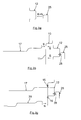
- a first method step first the aluminum rocker connecting plate 25 by means of a rivet and adhesive connection (K + N) connected to the hat-shaped steel reinforcing plate 12.
- K + N a rivet and adhesive connection
- This prefabricated assembly is then connected by means of a welded joint (S) on the hot steel sill inner panel 10, possibly simultaneously with the steel bottom support 17th
- the aluminum side sill plate 6 connected, once by a rivet and adhesive connection (K + N) in the first connection region 7 and by, for example, laser welding (LS) or by a rivet and adhesive joint welding in the second connection region 23rd
Abstract
Description
Die Erfindung betrifft eine Schwellerbaugruppe für eine Fahrzeugkarosserie nach dem Oberbegriff des Anspruchs 1 sowie ein Verfahren zur Herstellung einer Schwellerbaugruppe für eine Fahrzeugkarosserie nach dem Oberbegriff des Anspruchs 11.The invention relates to a sill subassembly for a vehicle body according to the preamble of claim 1 and to a method for producing a sill subassembly for a vehicle body according to the preamble of
Eine derartige Schwellerbaugruppe für eine selbsttragende Karosserie eines Fahrzeugs ist allgemein bekannt. Beispielsweise befindet sich eine derartige Schwellerbaugruppe unterhalb des Türeinstiegs, auf beiden Seiten des Fahrzeuges, zwischen den Radkästen vorne und hinten. Dem Schweller kommt eine wesentliche Aufgabe bei der Aufnahme von Kräften, zum Beispiel bei einem Frontalzusammenstoß zu. Beim Seitenaufprall ist es dagegen wichtig, im Bereich des Schwellers keine zu hohe Steifigkeit auszubilden, um die Aufprallenergie gezielt abbauen zu können und damit die Eindringgeschwindigkeiten reduzieren zu können. Der Schweller ist regelmäßig kein eigenes Bauteil und setzt sich aus einem Seitenteil, einem Verstärkungsteil und einem Schwellerinnenteil zusammen, welche ein Hohlprofil ausbilden. An das Schwellerinnenteil ist regelmäßig ein Bodenblech gefügt.Such a sill assembly for a self-supporting body of a vehicle is well known. For example, such a Schwellerbaugruppe is below the door entry, on both sides of the vehicle, between the front and rear wheel arches. The sill has an essential role to play in absorbing forces, for example in a head-on collision. In the case of a side impact, on the other hand, it is important not to create excessive rigidity in the region of the sill in order to be able to reduce the impact energy in a targeted manner and thus to be able to reduce the penetration speeds. The sill is regularly no separate component and is composed of a side part, a reinforcement part and a sill inner part, which form a hollow profile. At the Schwellerinnenteil is regularly joined a floor panel.
Ein derartiger Schweller ist beispielsweise aus der
Ein Schweller eines Kraftfahrzeugs mit einer Verstärkungseinlage ist ferner auch aus der
Eine derartige Mischbauweise, bei der herkömmliche Werkstoffe durch leichtere, hochfeste Werkstoffe ersetzt werden sollen, stellt eine vorrangige Aufgabe im modernen Fahrzeugkarosseriebau dar, um zum einen Gewichtseinsparungen vornehmen zu können und zum anderen auch um Fahrzeugkarosserien zur Verfügung zu stellen, die sich trotz gewichtsoptimierter Strukturen nach wie vor durch eine hohe Steifigkeit und Tragfähigkeit der Gesamtkonstruktion auszeichnen.Such a mixed construction, in which conventional materials are to be replaced by lighter, high-strength materials, represents a primary task in modern vehicle body construction in order to make a weight savings and on the other hand to provide vehicle bodies available, despite weight-optimized structures after as before distinguished by a high rigidity and load capacity of the overall construction.
Es ist daher Aufgabe der vorliegenden Erfindung, eine Schwellerbaugruppe für eine Fahrzeugkarosserie zur Verfügung zu stellen, die sich bei einem gewichtsoptimierten Aufbau gleichzeitig durch eine hohe Steifigkeit und Tragfähigkeit auszeichnet sowie weiter mit einer für einen Großserieneinsatz geeigneten Fügetechnik herstellbar ist. Des Weiteren ist es Aufgabe der vorliegenden Erfindung, ein Fertigungsverfahren für eine derartige Schwellerbaugruppe zur Verfügung zu stellen, mittels der diese Schwellerbaugruppe in der Großserie funktionssicher und fertigungstechnisch einfach hergestellt werden kann.It is therefore an object of the present invention to provide a Schwellerbaugruppe for a vehicle body, which is characterized at the same time in a weight-optimized structure by a high rigidity and load capacity and continue with a suitable for mass production joining technology can be produced. Furthermore, it is an object of the present invention to provide a manufacturing method for such a Schwellerbaugruppe available by means of which this Schwellerbaugruppe can be produced reliably in mass production and manufacturing technology.
Diese Aufgabe wird gelöst mit den Merkmalen der unabhängigen Patentansprüche. Vorteilhafte Ausgestaltungen sind Gegenstand der darauf rückbezogenen Unteransprüche.This object is achieved with the features of the independent claims. Advantageous embodiments are the subject of the dependent claims.
Gemäß Anspruch 1 ist eine Schwellerbaugruppe für eine Fahrzeugkarosserie vorgesehen, die ein Schwellerinnenteil, ein Schwellerverstärkungsteil und ein Schwellerseitenteil als Schließteil aufweist, die miteinander ein Schwellerhohlprofil ausbilden. Erfindungsgemäß ist das Schwellerseitenteil, im Querschnitt betrachtet, mit einem ersten Anbindungsbereich im Bereich der Schwellerbaugruppe, unmittelbar am Schwellerinnenteil, festgelegt, während zwischen dem Schwellerverstärkungsteil und dem Schwellerseitenteil, die aus unterschiedlichen Werkstoffen bzw. Materialien gefertigt sind, ein Schwellerverbindungsteil als separates Bauteil angeordnet ist, das mit dem Schwellerverstärkungsteil und mit einem zweiten Anbindungsbereich des Schwellerseitenteils fest verbunden ist, wobei bevorzugt vorgesehen ist, dass das Schwellerverbindungsteil aus dem gleichen Werkstoff wie das Schwellerverstärkungsteil oder das Schwellerseitenteil hergestellt ist.According to claim 1, a sill assembly for a vehicle body is provided, which has a sill inner part, a sill reinforcement part and a sill side part as a closing part, which together form a rocker hollow profile. According to the invention, the sill side part, viewed in cross section, with a first connection region in the region of the sill assembly, set directly at the sill inner part, while between the sill reinforcement part and the sill side part, which are made of different materials or materials, a sill connection part is arranged as a separate component, which is firmly connected to the sill reinforcement part and to a second connection region of the sill side part, wherein it is preferably provided that the sill connection part is made of the same material as the sill reinforcement part or the sill side part.
Mit einem derartigen Aufbau ergeben sich erhebliche konstruktive und fertigungstechnische Freiheitsgrade, insbesondere dann, wenn das Schwellerseitenteil zum Beispiel aus einem Leichtmetall, insbesondere einem Aluminium, wie dies nachfolgend am Beispiel eines Aluminium-Schwellerinnenteils noch näher erläutert wird, eingesetzt wird. Beispielsweise lassen sich hier dann Schwellerseitenteile aus einem Leichtmetall mit einer sehr einfachen und damit fertigungstechnisch bzw. ziehtechnisch einfach herstellbaren Geometrie einsetzen.With such a structure, considerable constructive and manufacturing-related degrees of freedom result, in particular when the sill side part for example, from a light metal, in particular an aluminum, as will be explained in more detail below using the example of an aluminum sill inner part, is used. For example, can then be used side parts made of a light metal with a very simple and thus manufacturing technology or drawing technology easy to produce geometry.
Durch den Einsatz des Schwellerverbindungsteils als separates Bauteil werden weiterhin erhebliche konstruktive Freiräume geschaffen, die einen für den jeweiligen Einzelfall optimierten Aufbau eines Schwellerhohlprofils ermöglichen. In Verbindung mit diesem Schwellerverbindungsteil ist es dabei von wesentlichem Vorteil, wenn dieses aus dem gleichen Werkstoff wie das Schwellerverstärkungsteil oder das Schwellerseitenteil hergestellt ist, da dann in diesem Fall eine herstellungstechnisch einfache und unkritische Verbindung zwischen zwei Bauteilen aus dem im Wesentlichen gleichen Material hergestellt werden kann.Through the use of the rocker connection part as a separate component considerable constructive open spaces are still created, which allow optimized for the respective individual case construction of a rocker hollow profile. In connection with this sill connecting part, it is of substantial advantage, if this is made of the same material as the sill reinforcement part or the sill side part, since then in this case a manufacturing technology simple and uncritical connection between two components can be made from the substantially same material ,
Das Schwellerseitenteil kann dabei mit seinem anderen Anbindungsbereich, der nicht am Schwellerverbindungsteil festgelegt wird, an unterschiedlichsten Bauteilen der Schwellerbaugruppe festgelegt werden, so zum Beispiel in einer bevorzugten Ausführungsform unmittelbar und direkt am Schwellerinnenteil, wenngleich auch die Anbindung am Schwellerverstärkungsteil oder einem anderen gegebenenfalls zusätzlichen Bauteil der Schwellerbaugruppe ebenfalls grundsätzlich möglich ist.The sill side part can be defined with its other connection area, which is not set on the sill connection part, to a variety of components of the sill assembly, so for example in a preferred embodiment directly and directly on the sill inner part, although the connection to the sill reinforcement part or any other additional component of Threshold assembly is also possible in principle.
Gemäß einer besonders bevorzugten Ausgestaltung der vorliegenden Erfindung ist vorgesehen, dass zwischen dem aus Stahl gefertigten Stahl-Schwellerverstärkungsteil und dem aus Aluminium gefertigten Aluminium-Schwellerseitenteil ein aus Aluminium gefertigtes Aluminium-Schwellerverbindungsteil angeordnet ist, das mit dem Stahl-Schwellerverstärkungsteil mittels einer Klebe- und/oder Nietverbindung verbunden ist und das mit dem Aluminium-Schwellerseitenteil mittels ebenfalls einer Klebe- und/oder Nietverbindung oder aber auch durch Warmfügen, insbesondere Laserschweißen verbunden ist. In letzterem Fall lassen sich dann die aneinanderliegenden Flanschbereiche deutlich gegenüber einer Flanschgestaltung für eine Klebe- und/oder Nietverbindung verkürzen. Bevorzugt sind dabei sämtliche Bauteile durch Bleche gebildet. Mit einem derartigen konkreten Aufbau, bei dem sowohl das Schwellerverstärkungsteil als auch das Schwellerverbindungsteil aus einem Leichtmetall, hier beispielsweise Aluminium, hergestellt sind, lässt sich eine besonders gewichtsgünstig optimierte Schwellerbaugruppe realisieren, wobei zudem durch die Laserschweißverbindung oder eine Klebe- und Nietverbindung zwischen dem Aluminium-Schwellerseitenteil und dem Aluminium-Schwellerverbindungsteil einerseits und einer Klebe- und Nietverbindung zwischen dem Stahl-Schwellerverstärkungsteil und dem Aluminium-Verbindungsteil eine hinreichende Hohlraumversiegelung des Hohlprofils erzielt wird und damit ein vorteilhafter Korrosionsschutz in diesem besonders spritzwassergefährdeten Schwellerbereich erzielt wird. Hier, wie auch nachfolgend, wird die Nietverbindung durch eine Mehrzahl von einzelnen, voneinander beabstandeten Nietpunkten gebildet, die bevorzugt durch Vollstanznieten hergestellt sind, wodurch sich eine besonders innige und feste Verbindung zwischen den miteinander zu verbindenden Bauteilen ergibt. Grundsätzlich ist jedoch auch der Einsatz von Halbhohlstanznieten möglich.According to a particularly preferred embodiment of the present invention, it is provided that between the steel-made rocker sill reinforcement part and the aluminum sill side part made of aluminum, an aluminum sill joint part made of aluminum is arranged, which with the steel sill reinforcement part is connected by means of an adhesive and / or rivet and which is connected to the aluminum sill side part also by means of an adhesive and / or rivet or even by hot-joining, in particular laser welding. In the latter case, then the abutting flange areas can be significantly shortened compared to a flange design for an adhesive and / or riveted joint. In this case, all components are preferably formed by sheets. With such a concrete construction, in which both the sill reinforcement part and the sill connection part are made of a light metal, here aluminum, for example, a particularly weight-optimized sill assembly can be realized, wherein moreover by the laser welding connection or an adhesive and riveted connection between the aluminum Sill side part and the aluminum sill connection part on the one hand and an adhesive and rivet connection between the steel sill reinforcement part and the aluminum connection part a sufficient cavity sealing of the hollow profile is achieved and thus an advantageous corrosion protection is achieved in this particularly splash-sensitive Schwellerbereich. Here, as well as below, the rivet connection is formed by a plurality of individual, spaced-apart rivet points, which are preferably produced by solid punch rivets, resulting in a particularly intimate and firm connection between the components to be joined together. Basically, however, the use of semi-hollow punch rivets is possible.
Gemäß einer weiteren besonders bevorzugten Ausgestaltung ist vorgesehen, dass das Stahl-Schwellerverstärkungsteil aus einem bevorzugt kaltgeformten Stahl hergestellt und mittels einer Warmfügeverbindung, insbesondere mittels einer Schweißverbindung mit dem aus einem warmgeformten Stahl hergestellten Warmstahl-Schwellerinnenteil verbunden ist. In diesem Fall ist dann bei einer bevorzugten, direkten und unmittelbaren Anbindung des Aluminium-Schwellerseitenteils an dem Warmstahl-Innenteil vorgesehen, dass diese Verbindung mittels einer Klebe- und/oder Nietverbindung erfolgt. Für bestimmte Einsatzfälle kann die hochfeste Nietverbindung aber gegebenenfalls auch durch eine Schraubverbindung ersetzt werden.According to a further particularly preferred embodiment, it is provided that the steel sill reinforcement part is made of a preferably cold-formed steel and connected by means of a hot joining, in particular by means of a welded connection with the hot steel sill inner part made of a thermoformed steel. In this case, then in a preferred, direct and immediate connection of Aluminum sill side part provided on the hot steel inner part, that this connection takes place by means of an adhesive and / or riveted joint. For certain applications, however, the high-strength rivet connection may also be replaced by a screw connection.
Die Begrifflichkeit kaltgeformter und warmgeformter Stahl soll hier zum Ausdruck bringen, dass es sich um unterschiedliche Stahlwerkstoffe bzw. - materialien handelt, die sich vor allem dadurch unterscheiden, dass der warmgeformte Stahl noch höherfester ausgebildet ist als der kaltgeformte Stahl.The term cold-formed and hot-formed steel is intended to express that these are different steel materials or materials, which differ in particular in that the hot-formed steel has a higher strength than the cold-formed steel.
Mit der eben aufgezeigten Werkstoffwahl und Ausführungsvariante wird bei einem gleichzeitig gewichtsoptimierten Aufbau eine besonders hohe Steifigkeit und Tragfähigkeit der Schwellerbaugruppe erzielt.With the material selection and design variant just outlined, a particularly high rigidity and load-bearing capacity of the rocker assembly is achieved with a construction which is weight-optimized at the same time.
Letzteres ist vor allem auch dann der Fall, wenn gemäß einer weiteren bevorzugten Ausgestaltung vorgesehen ist, dass an dem Warmstahl-Innenteil, im Querschnitt betrachtet, auf der dem Stahl-Schwellerverstärkungsteil abgewandten Seite, ein aus einem zum Beispiel kaltgeformten Stahl hergestellter Stahl-Bodenträger mittels einer Warmfügeverbindung, insbesondere mittels einer Schweißverbindung, und/oder eine aus Aluminium hergestellte Aluminium-Bodenwand mittels einer Klebe- und/oder Nietverbindung angebunden sind. Besonders bevorzugt ist hierbei ein Aufbau, bei dem ein Stahlbodenblech in Fahrzeughochachsenrichtung gesehen beabstandet oberhalb einer Aluminium-Bodenwand in Anbindungsbereich des Stahl-Schwellerverstärkungsteils so, bevorzugt flächig, am Warmstahl-Schwellerinnenteil angebunden ist, dass das Stahl-Schwellerverstärkungsteil und der Stahl-Bodenträger mittels derselben Schweißverbindung am Warmstahl-Schwellerinnenteil festgelegt sind. Dadurch lässt sich der Fertigungsaufwand vorteilhaft reduzieren und gleichzeitig eine hochfeste Verbindung zwischen den einzelnen Bauteilen darstellen.The latter is especially the case when it is provided according to a further preferred embodiment that on the hot steel inner part, viewed in cross section, on the side facing away from the steel sill reinforcement part, made of a cold-formed steel, for example, steel floor support means a hot-joining, in particular by means of a welded connection, and / or an aluminum bottom wall made of aluminum are connected by means of an adhesive and / or rivet connection. Particularly preferred here is a structure in which a steel bottom plate in vehicle vertical axis direction seen above an aluminum bottom wall in connection region of the steel sill reinforcement part so, preferably flat, is connected to the hot steel sill inner part, that the steel sill reinforcement part and the steel bottom support means of the same Welded connection are fixed to the high-pressure steel inner part of the sill. This allows the Reduce manufacturing costs advantageous and simultaneously represent a high-strength connection between the individual components.
Das Schwellerinnenteil kann, im Querschnitt betrachtet, bevorzugt eine sich im montierten Zustand an den Schwellerverstärkungs-Anschlussbereich nach oben in Fahrzeughochachsenrichtung hin anschließenden und das Schwellerinnenteil nach oben hin überragenden Schwellerseitenteil-Anschlussbereich aufweisen, an dem das Schwellerseitenteil dann angebunden ist, und zwar bevorzugt in einer flächigen Anlageverbindung anliegend angebunden ist, wodurch sich eine besonders stabile und hochwertige sowie hochfeste Anbindung des Schwellerseitenteils am Schwellerinnenteil ergibt. Für einfache Schwellerseitenteil-Geometrien, was insbesondere in Verbindung mit einem Schwellerseitenteil aus einem Leichtmetall, wie zum Beispiel Aluminium, aus fertigungstechnischer Sicht von Vorteil ist, ist es dabei besonders vorteilhaft, wenn der Schwellerseitenteil-Anschlussbereich in Richtung zum Schwellerseitenteil hin abgekantet ausgebildet ist, und zwar bevorzugt so abgekantet ausgebildet ist, dass sich an einen in etwa in Fahrzeugquerrichtung verlaufenden ersten Abschnitt ein abgewinkelter und sich in etwa Fahrzeughochachsenrichtung erstreckender Flanschabschnitt anschließt, an dem das Schwellerseitenteil in einer flächigen Anlageverbindung anliegt und dort angebunden ist.The sill inner part may, viewed in cross-section, preferably have a in the mounted state of the sill reinforcement connection area upwards in the vehicle vertical axis direction down and the sill inner part upwardly projecting sill side part connection area to which the sill side part is then connected, preferably in one flat system connection is connected adjacent, resulting in a particularly stable and high-quality and high-strength connection of the side sill part on the inner part of the sill. For simple side member sill geometries, which is particularly advantageous in connection with a sill side part of a light metal, such as aluminum, from a production point of view, it is particularly advantageous if the sill side member connection portion is formed bent towards the sill side part, and Although preferably so bent is formed that adjoins an approximately extending in the vehicle transverse direction of the first section an angled and approximately vehicle vertical axis extending flange portion on which the rocker side member abuts in a flat contact connection and is connected there.
Das Schwellerverbindungsteil selbst weist, im Querschnitt betrachtet, bevorzugt eine in etwa U-förmige Geometrie mit zwei beabstandet gegenüberliegenden, bevorzugt im Wesentlichen parallel zueinander ausgerichteten, U-Schenkeln auf, die eine gleiche als auch eine unterschiedliche Länge aufweisen können. In Verbindung mit derartigen U-Schenkeln ist auf einfache Weise sichergestellt, dass das Schwellerseitenteil und das Schwellerverbindungsteil jeweils in einer flächigen Anlageverbindung an den U-Schenkeln, insbesondere an den voneinander abgewandten Schenkelaußenseiten, anliegen und dort angebunden sein können. Dadurch lässt sich eine hochfeste Verbindung zwischen den einzelnen Bauteilen, insbesondere auch in Verbindung mit einer gewünschten Dichtigkeit in diesem Bereich auf einfache und funktionssichre Weise herstellen.The sill connection part itself has, viewed in cross-section, preferably an approximately U-shaped geometry with two spaced opposite, preferably substantially parallel aligned, U-legs, which may have the same as well as a different length. In conjunction with such U-legs is ensured in a simple manner that the sill side part and the sill connection part in each case in a planar abutment connection to the U-legs, in particular on the opposite sides Schenkelaußenseiten, abut and be connected there. This makes it possible to produce a high-strength connection between the individual components, in particular in conjunction with a desired tightness in this area in a simple and functionally reliable manner.
Wie bereits zuvor dargestellt, lassen sich mit einem erfindungsgemäßen Aufbau einfache Leichtmetall-Schwellerseitenteil-Geometrien realisieren, was aus fertigungstechnischer Sicht von besonderem Vorteil ist. Bevorzugt weist somit das Schwellerseitenteil, im Querschnitt betrachtet, eine im Wesentlichen in Fahrzeughochachsenrichtung verlaufende Längserstreckungsrichtung auf, wobei aber auch bevorzugt in einem mittleren Bereich zwischen den beiden Schwellerseitenteil-Anbindungsbereichen eine nach außen von dem Schwellerinnenteil weggerichtete Auswölbung vorgesehen sein kann, um ein entsprechendes Schwellervolumen auszubilden.As already shown above, can be realized with a structure according to the invention simple light metal sill side member geometries, which is from the production point of view of particular advantage. Preferably, therefore, the sill side part, viewed in cross-section, extending substantially in the vehicle vertical axis direction of elongation direction, but also preferably in a central region between the two side member connecting portion-side outwardly directed away from the sill inner portion bulge may be provided to form a corresponding threshold volume ,
Gemäß einem besonders bevorzugten Verfahren zur Herstellung einer derartigen Schwellerbaugruppe, wie sie zuvor in Verbindung mit der allgemeinen Grundidee und den spezifischeren, bevorzugten Ausführungsformen gewürdigt worden ist, ist vorgesehen, dass das Aluminium-Schwellerverbindungsteil zuerst am Stahl-Schwellerverstärkungsteil angeklebt und/oder angenietet wird, bevorzugt aus Korrosionsschutzgründen dort angeklebt und angenietet wird. Diese so vorgefertigte Baugruppe wird dann am Warmstahl-Innenteil bevorzugt angeschweißt. Gegebenenfalls kann in diesem Zusammenhang gleichzeitig auch die Anbindung eines Stahl-Bodenträgers am Warmstahl-Schwellerinnenteil erfolgen, insbesondere dann, wenn die gleiche Schweißverbindung zur Festlegung des Schwellerverstärkungsteils verwendet wird.According to a particularly preferred method of manufacturing such a sill assembly, as previously appreciated in connection with the generic and more specific preferred embodiments, it is contemplated that the aluminum sill fastener member is first adhered and / or riveted to the steel sill reinforcement member, preferably for corrosion protection reasons glued and riveted there. This prefabricated assembly is then preferably welded to the hot steel inner part. Optionally, in this context, the connection of a steel bottom support on the high-pressure steel inner edge part take place at the same time, in particular when the same welded joint is used for fixing the sill reinforcement part.
In einem weiteren Verfahrensschritt wird dann das Aluminium-Schwellerseitenteil mit einem ersten Anbindungsbereich am Warmstahl-Schwellerinnenteil angenietet sowie gegebenenfalls angeklebt und mit einem zweiten Anbindungsbereich am Aluminium-Verbindungsteil angenietet sowie gegebenenfalls angeklebt oder mittels Laserschweißen angeschweißt.In a further method step then the aluminum sill side part with a first connection area on the hot steel sill inner part riveted and optionally glued and riveted to a second connection area on the aluminum connection part and optionally glued or welded by laser welding.
Mit einer derartigen Verfahrensführung ist stets eine fertigungstechnisch besonders einfache und bevorzugte Zugänglichkeit zu den einzelnen Anbindungsbereichen gegeben, was den Fertigungsablauf insgesamt wesentlich erleichtert.With such a process management is always a manufacturing technology particularly simple and preferred accessibility given to the individual connection areas, which greatly facilitates the overall manufacturing process.
Die Erfindung wird nachfolgend anhand einer Zeichnung näher erläutert.The invention will be explained in more detail with reference to a drawing.
Es zeigen:
- Fig. 1
- schematisch einen Ausschnitt aus einem seitlichen Bereich einer Kraftfahrzeugkarosserie mitsamt Schwellerbaugruppe,
- Fig. 2
- schematisch einen Schnitt entlang der Linie A-A der
Fig. 1 , und - Fig. 3a bis 3d
- schematisch die Herstellung einer erfindungsgemäßen Schwellerbaugruppe in den einzelnen Phasen.
- Fig. 1
- schematically a section of a lateral region of a motor vehicle body including sill assembly,
- Fig. 2
- schematically a section along the line AA of
Fig. 1 , and - Fig. 3a to 3d
- schematically the production of a Schwellerbaugruppe according to the invention in the individual phases.
In der
Die
Der Flanschabschnitt 8 ist Bestandteil eines Warmstahl-Schwellerinnenblechs 10 als Schwellerinnenteil, das einen ebenen, sich in etwa in Fahrzeughochachsenrichtung verlaufenden Schwellerverstärkungsteil-Anschlussbereich 11 aufweist, an dem ein im Querschnitt betrachtet hutförmiges Stahl-Schwellerverstärkungsblech 12 mit seinen abgewinkelten, flanschartigen Schenkelenden 13, 14 in einer flächigen Anlageverbindung anliegt und mit dem Warmstahl-Schwellerinnenblech mittels jeweils einer Schweißverbindung 15, 16 angebunden ist.The
Auf der gegenüberliegenden Seite der Anbindung des Schenkelendes 13 des Stahl-Schwellerverstärkungsblechs 12 ist bevorzugt ein Stahl-Bodenträger 17 mittels eines abgewinkelten Flansches 18 flächig angelegt und ebenfalls mittels der Schweißverbindung 15 am Warmstahl-Schwellerinnenblech 10 angebunden.On the opposite side of the connection of the
Das Warmstahl-Schwellerinnenblech 10 ist, wie dies aus der
An einem in Fahrzeughochachsenrichtung gesehenen unteren Bereich des Schwellerverstärkungsteil-Anschlussbereichs 11 des Warmstahl-Schwellerinnenblechs 10 ist ferner noch eine Aluminiumbodenwand 20 mittels einer Nietverbindung 21 angebunden, die ebenfalls wiederum analog zu der Nietverbindung 9 ausgebildet sein kann. Auch hier ist wiederum bevorzugt vorgesehen, zwischen einem Flanschabschnitt 22 der Aluminium-Bodenwand 20, der in einer flächigen Anlageverbindung an dem Schwellerverstärkungsteil-Anschlussbereich 11 anliegt und eben diesem Schwellerverstärkungsteil-Anschlussbereich 11 eine Klebstoffverbindung vorzusehen, um den Aufbau insgesamt abzudichten und eine besonders hochfeste Anbindung zur Verfügung zu stellen.At a lower region of the sill reinforcement
Wie dies aus der
Wie dies der
Anschließend wird dann, wie dies in der
- 11
- Fahrzeugkarosserievehicle body
- 22
- Schwellerbaugruppesill assembly
- 33
- A-SäuleA column
- 44
- B-SäuleB-pillar
- 55
- C-SäuleC-pillar
- 66
- Aluminium-SchwellerseitenblechAluminum sill side plate
- 77
- erster Anbindungsbereichfirst connection area
- 88th
- Flanschabschnittflange
- 99
- Nietverbindungrivet
- 1010
- Warmstah-SchwellerinnenblechWarmstah-rocker inner sheet
- 1111
- Schwellerverstärkungsteil-AnschlussbereichSill reinforcement member port area
- 1212
- Stahl-SchwellerverstärkungsblechSteel-sill reinforcement plate
- 1313
- Schenkelendeleg end
- 1414
- Schenkelendeleg end
- 1515
- Schweißverbindungwelded joint
- 1616
- Schweißverbindungwelded joint
- 1717
- Stahl-BodenträgerSteel floor support
- 1818
- Flanschflange
- 1919
- Blechabschnittsheet metal section
- 2020
- Aluminium-BodenwandAluminum bottom wall
- 2121
- Nietverbindungrivet
- 2222
- Flanschabschnittflange
- 2323
- zweiter Anbindungsbereichsecond connection area
- 2424
- U-SchenkelU-leg
- 2525
- Aluminium-SchwellerverbindungsblechAluminum sill connecting plate
- 2626
- LaserschweißverbindungLaser welded joint
- 2727
- U-SchenkelU-leg
- 2828
- Niet- und KlebeverbindungRivet and adhesive connection
- 2929
- Auswölbungbulge
Claims (11)
dadurch gekennzeichnet,
dass das Schwellerseitenteil (6), im Querschnitt betrachtet, mit einem ersten Anbindungsbereich (7) im Bereich der Schwellerbaugruppe, bevorzugt unmittelbar am Schwellerinnenteil (10), festgelegt ist, und dass zwischen dem Schwellerverstärkungsteil (12) und dem Schwellerseitenteil (6), die aus unterschiedlichen Werkstoffen gefertigt sind, ein Schwellerverbindungsteil (25) als separates Bauteil angeordnet ist, das mit dem Schwellerverstärkungsteil (12) und mit einem zweiten Anbindungsbereich (23) des Schwellerseitenteils (6) fest verbunden ist, wobei bevorzugt vorgesehen ist, dass das Schwellerverbindungsteil (25) aus dem gleichen Werkstoff wie das Schwellerverstärkungsteil (12) oder das Schwellerseitenteil (6) hergestellt ist.Threshold assembly for a vehicle body, comprising a sill inner part, a sill reinforcement part and a sill side part as a closing part, which form a rocker hollow profile,
characterized,
that the rocker side part (6), as viewed in cross section, with a first connection region (7) in the region of the rocker assembly, preferably directly on the sill inner part (10) is fixed, and that between the sill reinforcement part (12) and the rocker side part (6) are made of different materials, a sill connection part (25) is arranged as a separate component which is fixedly connected to the sill reinforcement part (12) and with a second connection region (23) of the sill side part (6), wherein it is preferably provided that the sill connection part ( 25) is made of the same material as the sill reinforcement part (12) or the sill side part (6).
dass weiter das Aluminium-Schwellerseitenteil (6) mittels einer Klebe-und/oder Nietverbindung (9) mit dem Warmstahl-Schwellerinnenteil (10) verbunden ist.Sill assembly according to claim 2, characterized in that the steel sill reinforcement part (12) is made of a preferably cold-formed steel and by means of a hot joining compound (15, 16), preferably a welded joint (15, 16), with the hot steel made of a thermoformed steel -Schwellerinnenteil (10) is connected, and
in that the aluminum sill side part (6) is furthermore connected to the hot steel sill inner part (10) by means of an adhesive and / or rivet connection (9).
dass der Schwellerseitenteil-Anschlussbereich in Richtung zum Schwellerseitenteil (6) hin abgekantet ist, höchst bevorzugt so abgekantet ist, dass sich an einen in etwa in Fahrzeugquerrichtung verlaufenden ersten Abschnitt (19) ein abgewinkelter und sich in etwa in Fahrzeughochachsenrichtung erstreckender Flauschabschnitt (8) anschließt, an dem das Schwellerseitenteil (6) in einer flächigen Anlageverbindung anliegt und angebunden ist.Threshold assembly according to claim 7, characterized
in that the sill side part connection region is bent in the direction of the sill side part (6), most preferably is bent so that it is approximately at the vehicle transverse direction extending first portion (19) adjoins an angled and approximately in the vehicle vertical axis extending Velcro portion (8) on which the rocker side part (6) rests in a planar contact connection and is connected.
dass das Schwellerseitenteil (6) und das Schwellerverbindungsteil (25) jeweils in einer flächigen Anlageverbindung an den U-Schenkeln (24, 27), insbesondere an den voneinander abgewandten Schenkelaußenseiten, anliegen und dort angebunden sind.Sill assembly according to one of claims 1 to 8, characterized in that the sill connection part (25), viewed in cross section, an approximately U-shaped geometry with two spaced opposite, preferably substantially parallel aligned, U-legs (24, 27) has, and
in that the sill side part (6) and the sill connection part (25) abut each other in a planar abutment connection on the U-limbs (24, 27), in particular on the outer thighs facing away from each other, and are connected there.
dass das Aluminium-Schwellerverbindungsteil (25) zuerst am Stahl-Schwellerverstärkungsteil (12) angeklebt und/oder angenietet wird,
dass anschließend die so gefertigte Baugruppe, gegebenenfalls unter gleichzeitiger Anbindung eines Stahl-Bodenträgers (17) am Warmstahl-Schwellerinnenteil (10) mittels einer Warmfügeverbindung angebunden, insbesondere angeschweißt wird, und
dass weiter das Aluminium-Schwellerseitenteil (6) mit einem ersten Anbindungsbereich (7) am Warmstahl-Schwellerinnenteil (10) angenietet sowie gegebenenfalls angeklebt und mit einem zweiten Anbindungsbereich am Aluminium-Schwellerverbindungsteil (25) angenietet sowie gegebenenfalls angeklebt oder mittels Laserschweißen angeschweißt wird.Method for producing a sill subassembly for a vehicle body according to one of the preceding claims, characterized
that the aluminum sill connection portion (25) adhered to the first steel-sill reinforcing member (12) and / or riveted,
that subsequently the assembly produced in this way, optionally with the simultaneous connection of a steel bottom support (17) to the hot steel sill inner part (10) is connected, in particular welded, by means of a hot-joining connection, and
in that the aluminum sill side part (6) is further riveted to the hot steel sill inner part (10) and optionally glued and riveted to the aluminum sill connection part (25) with a second connection region and optionally adhesively bonded or welded by means of laser welding.
Applications Claiming Priority (1)
| Application Number | Priority Date | Filing Date | Title |
|---|---|---|---|
| DE200910058976 DE102009058976A1 (en) | 2009-12-18 | 2009-12-18 | Threshold assembly for a vehicle body and method of making a sill assembly |
Publications (2)
| Publication Number | Publication Date |
|---|---|
| EP2336007A1 true EP2336007A1 (en) | 2011-06-22 |
| EP2336007B1 EP2336007B1 (en) | 2013-09-11 |
Family
ID=43797819
Family Applications (1)
| Application Number | Title | Priority Date | Filing Date |
|---|---|---|---|
| EP20100007138 Not-in-force EP2336007B1 (en) | 2009-12-18 | 2010-07-10 | Side sill assembly for a vehicle body |
Country Status (2)
| Country | Link |
|---|---|
| EP (1) | EP2336007B1 (en) |
| DE (1) | DE102009058976A1 (en) |
Cited By (3)
| Publication number | Priority date | Publication date | Assignee | Title |
|---|---|---|---|---|
| EP3159245A1 (en) * | 2015-10-22 | 2017-04-26 | Constellium Singen GmbH | Rigid structure comprising a two-part local reinforcing element |
| US9776664B2 (en) | 2015-03-18 | 2017-10-03 | Honda Motor Co., Ltd. | Impact transmission structure |
| CN113165700A (en) * | 2018-12-20 | 2021-07-23 | 宝马股份公司 | Side sill beam for automobile |
Families Citing this family (2)
| Publication number | Priority date | Publication date | Assignee | Title |
|---|---|---|---|---|
| DE102013113164B4 (en) | 2013-11-28 | 2022-07-07 | Dr. Ing. H.C. F. Porsche Aktiengesellschaft | rocker assembly |
| KR102440609B1 (en) * | 2017-12-27 | 2022-09-05 | 현대자동차 주식회사 | Side vehicle body reinforcing structure |
Citations (8)
| Publication number | Priority date | Publication date | Assignee | Title |
|---|---|---|---|---|
| EP1024073A1 (en) * | 1999-01-29 | 2000-08-02 | Mazda Motor Corporation | Body structure of motor vehicle |
| EP1024074A1 (en) * | 1999-01-29 | 2000-08-02 | Mazda Motor Corporation | Body structure of motor vehicle |
| DE19708215C2 (en) | 1997-02-28 | 2001-06-28 | Audi Ag | Sill of a motor vehicle with a reinforcement insert |
| JP2006264476A (en) * | 2005-03-23 | 2006-10-05 | Kobe Steel Ltd | Automobile panel structure |
| DE102005043698A1 (en) * | 2005-09-14 | 2007-03-15 | Daimlerchrysler Ag | Side door sill for motor vehicle body, has structural part comprising fiber-reinforced plastic part that is supported at one of partial shells of box section, which is tightened within region of passenger compartment |
| EP1840003A2 (en) * | 2006-03-31 | 2007-10-03 | Dr.Ing.h.c. F. Porsche Aktiengesellschaft | Door sill reinforcing element for a car body |
| EP2014539A1 (en) * | 2007-07-11 | 2009-01-14 | Dr.Ing. h.c.F. Porsche Aktiengesellschaft | Motor vehicle body with side sills |
| DE102008020081A1 (en) | 2008-04-22 | 2009-10-29 | Dr. Ing. H.C. F. Porsche Aktiengesellschaft | Door sill i.e. aluminum strand profile, for body of motor vehicle, has inside and outside panels connected to door sill panel so as to close door sill, and reinforcement profile provided between inside and outside panels |
Family Cites Families (1)
| Publication number | Priority date | Publication date | Assignee | Title |
|---|---|---|---|---|
| DE102005038463A1 (en) * | 2005-08-13 | 2007-02-15 | Daimlerchrysler Ag | Carrier member for a vehicle bodywork, as a box profile of two part-shells, has an inner reinforcement profile of two shells bonded to the part-shells |
-
2009
- 2009-12-18 DE DE200910058976 patent/DE102009058976A1/en not_active Withdrawn
-
2010
- 2010-07-10 EP EP20100007138 patent/EP2336007B1/en not_active Not-in-force
Patent Citations (8)
| Publication number | Priority date | Publication date | Assignee | Title |
|---|---|---|---|---|
| DE19708215C2 (en) | 1997-02-28 | 2001-06-28 | Audi Ag | Sill of a motor vehicle with a reinforcement insert |
| EP1024073A1 (en) * | 1999-01-29 | 2000-08-02 | Mazda Motor Corporation | Body structure of motor vehicle |
| EP1024074A1 (en) * | 1999-01-29 | 2000-08-02 | Mazda Motor Corporation | Body structure of motor vehicle |
| JP2006264476A (en) * | 2005-03-23 | 2006-10-05 | Kobe Steel Ltd | Automobile panel structure |
| DE102005043698A1 (en) * | 2005-09-14 | 2007-03-15 | Daimlerchrysler Ag | Side door sill for motor vehicle body, has structural part comprising fiber-reinforced plastic part that is supported at one of partial shells of box section, which is tightened within region of passenger compartment |
| EP1840003A2 (en) * | 2006-03-31 | 2007-10-03 | Dr.Ing.h.c. F. Porsche Aktiengesellschaft | Door sill reinforcing element for a car body |
| EP2014539A1 (en) * | 2007-07-11 | 2009-01-14 | Dr.Ing. h.c.F. Porsche Aktiengesellschaft | Motor vehicle body with side sills |
| DE102008020081A1 (en) | 2008-04-22 | 2009-10-29 | Dr. Ing. H.C. F. Porsche Aktiengesellschaft | Door sill i.e. aluminum strand profile, for body of motor vehicle, has inside and outside panels connected to door sill panel so as to close door sill, and reinforcement profile provided between inside and outside panels |
Cited By (4)
| Publication number | Priority date | Publication date | Assignee | Title |
|---|---|---|---|---|
| US9776664B2 (en) | 2015-03-18 | 2017-10-03 | Honda Motor Co., Ltd. | Impact transmission structure |
| EP3159245A1 (en) * | 2015-10-22 | 2017-04-26 | Constellium Singen GmbH | Rigid structure comprising a two-part local reinforcing element |
| CN113165700A (en) * | 2018-12-20 | 2021-07-23 | 宝马股份公司 | Side sill beam for automobile |
| CN113165700B (en) * | 2018-12-20 | 2023-10-03 | 宝马股份公司 | Side sill beam for an automobile, modular system and method |
Also Published As
| Publication number | Publication date |
|---|---|
| EP2336007B1 (en) | 2013-09-11 |
| DE102009058976A1 (en) | 2011-06-22 |
Similar Documents
| Publication | Publication Date | Title |
|---|---|---|
| EP2535241B1 (en) | Frame support structure for chassis frames of commercial vehicles, in particular heavy duty vehicles and/or buses | |
| EP1840003B1 (en) | Door sill reinforcing element for a car body | |
| DE19708215C2 (en) | Sill of a motor vehicle with a reinforcement insert | |
| EP2593338A1 (en) | B-pillar reinforcement in a motor vehicle | |
| EP2137048B1 (en) | Chassis component for a motor vehicle | |
| EP2357120B1 (en) | Support structure of a vehicle body in door sill area of a C pillar | |
| EP2336007B1 (en) | Side sill assembly for a vehicle body | |
| DE202021103263U1 (en) | Bumper arrangement with additional support | |
| DE102021102366B4 (en) | Bumper arrangement for a motor vehicle | |
| WO2018060143A1 (en) | Structural component for a motor vehicle body | |
| DE10256608A1 (en) | Sidewall module for a motor vehicle and manufacturing method for a motor vehicle body | |
| WO2011032715A1 (en) | Vehicle bodywork structure in the floor region of the occupant compartment and associated manufacturing method | |
| DE19852976B4 (en) | Door frame for a passenger car | |
| DE102014114348A1 (en) | Support frame structure and method for producing a support frame structure for a motor vehicle | |
| EP4035952B1 (en) | Bumper assembly with additional support | |
| DE102009021964A1 (en) | Hollow profile i.e. longitudinal carrier, for self-supporting body of motor vehicle, has molded shells provided with lateral connection flanges, where one flange is formed as wall section directly lining hollow cross-section of profile | |
| DE102010049427A1 (en) | Cross beam arrangement, particularly heel plate arrangement for use in vehicle body, particularly in motor vehicle body, has sheet metal carrier positively enclosing and overlapping middle tunnel in defined area | |
| DE10357907B4 (en) | Door pillar for a support frame structure | |
| DE102007018458B4 (en) | Body component for a motor vehicle and method for its production | |
| DE102015000979B3 (en) | Frame element, in particular side wall frame element, for a vehicle body and method for producing a frame member for a vehicle body | |
| EP1357017B1 (en) | Vehicle spaceframe | |
| DE102010064591B3 (en) | Cross member arrangement, in particular heel plate arrangement, in a vehicle body | |
| DE102004013511A1 (en) | body pillar | |
| DE102009030432A1 (en) | Hybrid assembly for motor vehicle, comprises a first component made of first metal alloy, and a second component made of second metal alloy, where the components are connected to each other in a joining area | |
| WO2013041177A1 (en) | Roof frame part for a body of a passenger motor vehicle |
Legal Events
| Date | Code | Title | Description |
|---|---|---|---|
| PUAI | Public reference made under article 153(3) epc to a published international application that has entered the european phase |
Free format text: ORIGINAL CODE: 0009012 |
|
| AK | Designated contracting states |
Kind code of ref document: A1 Designated state(s): AL AT BE BG CH CY CZ DE DK EE ES FI FR GB GR HR HU IE IS IT LI LT LU LV MC MK MT NL NO PL PT RO SE SI SK SM TR |
|
| AX | Request for extension of the european patent |
Extension state: BA ME RS |
|
| 17P | Request for examination filed |
Effective date: 20111222 |
|
| RIC1 | Information provided on ipc code assigned before grant |
Ipc: B62D 21/15 20060101AFI20130108BHEP Ipc: B62D 29/00 20060101ALI20130108BHEP Ipc: B62D 25/02 20060101ALI20130108BHEP |
|
| GRAP | Despatch of communication of intention to grant a patent |
Free format text: ORIGINAL CODE: EPIDOSNIGR1 |
|
| INTG | Intention to grant announced |
Effective date: 20130425 |
|
| RIN1 | Information on inventor provided before grant (corrected) |
Inventor name: WEIGL, WILLI Inventor name: CARLE, KLAUS-DIETER Inventor name: RUESS, MARCO |
|
| GRAS | Grant fee paid |
Free format text: ORIGINAL CODE: EPIDOSNIGR3 |
|
| GRAA | (expected) grant |
Free format text: ORIGINAL CODE: 0009210 |
|
| AK | Designated contracting states |
Kind code of ref document: B1 Designated state(s): AL AT BE BG CH CY CZ DE DK EE ES FI FR GB GR HR HU IE IS IT LI LT LU LV MC MK MT NL NO PL PT RO SE SI SK SM TR |
|
| REG | Reference to a national code |
Ref country code: GB Ref legal event code: FG4D Free format text: NOT ENGLISH |
|
| REG | Reference to a national code |
Ref country code: CH Ref legal event code: EP |
|
| REG | Reference to a national code |
Ref country code: AT Ref legal event code: REF Ref document number: 631459 Country of ref document: AT Kind code of ref document: T Effective date: 20130915 |
|
| REG | Reference to a national code |
Ref country code: IE Ref legal event code: FG4D Free format text: LANGUAGE OF EP DOCUMENT: GERMAN |
|
| REG | Reference to a national code |
Ref country code: DE Ref legal event code: R096 Ref document number: 502010004666 Country of ref document: DE Effective date: 20131107 |
|
| PG25 | Lapsed in a contracting state [announced via postgrant information from national office to epo] |
Ref country code: SE Free format text: LAPSE BECAUSE OF FAILURE TO SUBMIT A TRANSLATION OF THE DESCRIPTION OR TO PAY THE FEE WITHIN THE PRESCRIBED TIME-LIMIT Effective date: 20130911 Ref country code: CY Free format text: LAPSE BECAUSE OF FAILURE TO SUBMIT A TRANSLATION OF THE DESCRIPTION OR TO PAY THE FEE WITHIN THE PRESCRIBED TIME-LIMIT Effective date: 20130724 Ref country code: NO Free format text: LAPSE BECAUSE OF FAILURE TO SUBMIT A TRANSLATION OF THE DESCRIPTION OR TO PAY THE FEE WITHIN THE PRESCRIBED TIME-LIMIT Effective date: 20131211 Ref country code: LT Free format text: LAPSE BECAUSE OF FAILURE TO SUBMIT A TRANSLATION OF THE DESCRIPTION OR TO PAY THE FEE WITHIN THE PRESCRIBED TIME-LIMIT Effective date: 20130911 Ref country code: HR Free format text: LAPSE BECAUSE OF FAILURE TO SUBMIT A TRANSLATION OF THE DESCRIPTION OR TO PAY THE FEE WITHIN THE PRESCRIBED TIME-LIMIT Effective date: 20130911 |
|
| REG | Reference to a national code |
Ref country code: NL Ref legal event code: VDEP Effective date: 20130911 |
|
| REG | Reference to a national code |
Ref country code: LT Ref legal event code: MG4D |
|
| PG25 | Lapsed in a contracting state [announced via postgrant information from national office to epo] |
Ref country code: FI Free format text: LAPSE BECAUSE OF FAILURE TO SUBMIT A TRANSLATION OF THE DESCRIPTION OR TO PAY THE FEE WITHIN THE PRESCRIBED TIME-LIMIT Effective date: 20130911 Ref country code: LV Free format text: LAPSE BECAUSE OF FAILURE TO SUBMIT A TRANSLATION OF THE DESCRIPTION OR TO PAY THE FEE WITHIN THE PRESCRIBED TIME-LIMIT Effective date: 20130911 Ref country code: SI Free format text: LAPSE BECAUSE OF FAILURE TO SUBMIT A TRANSLATION OF THE DESCRIPTION OR TO PAY THE FEE WITHIN THE PRESCRIBED TIME-LIMIT Effective date: 20130911 Ref country code: GR Free format text: LAPSE BECAUSE OF FAILURE TO SUBMIT A TRANSLATION OF THE DESCRIPTION OR TO PAY THE FEE WITHIN THE PRESCRIBED TIME-LIMIT Effective date: 20131212 |
|
| PG25 | Lapsed in a contracting state [announced via postgrant information from national office to epo] |
Ref country code: CY Free format text: LAPSE BECAUSE OF FAILURE TO SUBMIT A TRANSLATION OF THE DESCRIPTION OR TO PAY THE FEE WITHIN THE PRESCRIBED TIME-LIMIT Effective date: 20130911 |
|
| PG25 | Lapsed in a contracting state [announced via postgrant information from national office to epo] |
Ref country code: NL Free format text: LAPSE BECAUSE OF FAILURE TO SUBMIT A TRANSLATION OF THE DESCRIPTION OR TO PAY THE FEE WITHIN THE PRESCRIBED TIME-LIMIT Effective date: 20130911 Ref country code: RO Free format text: LAPSE BECAUSE OF FAILURE TO SUBMIT A TRANSLATION OF THE DESCRIPTION OR TO PAY THE FEE WITHIN THE PRESCRIBED TIME-LIMIT Effective date: 20130911 Ref country code: SK Free format text: LAPSE BECAUSE OF FAILURE TO SUBMIT A TRANSLATION OF THE DESCRIPTION OR TO PAY THE FEE WITHIN THE PRESCRIBED TIME-LIMIT Effective date: 20130911 Ref country code: IS Free format text: LAPSE BECAUSE OF FAILURE TO SUBMIT A TRANSLATION OF THE DESCRIPTION OR TO PAY THE FEE WITHIN THE PRESCRIBED TIME-LIMIT Effective date: 20140111 Ref country code: EE Free format text: LAPSE BECAUSE OF FAILURE TO SUBMIT A TRANSLATION OF THE DESCRIPTION OR TO PAY THE FEE WITHIN THE PRESCRIBED TIME-LIMIT Effective date: 20130911 Ref country code: CZ Free format text: LAPSE BECAUSE OF FAILURE TO SUBMIT A TRANSLATION OF THE DESCRIPTION OR TO PAY THE FEE WITHIN THE PRESCRIBED TIME-LIMIT Effective date: 20130911 |
|
| PG25 | Lapsed in a contracting state [announced via postgrant information from national office to epo] |
Ref country code: ES Free format text: LAPSE BECAUSE OF FAILURE TO SUBMIT A TRANSLATION OF THE DESCRIPTION OR TO PAY THE FEE WITHIN THE PRESCRIBED TIME-LIMIT Effective date: 20130911 Ref country code: PL Free format text: LAPSE BECAUSE OF FAILURE TO SUBMIT A TRANSLATION OF THE DESCRIPTION OR TO PAY THE FEE WITHIN THE PRESCRIBED TIME-LIMIT Effective date: 20130911 |
|
| REG | Reference to a national code |
Ref country code: DE Ref legal event code: R097 Ref document number: 502010004666 Country of ref document: DE |
|
| PG25 | Lapsed in a contracting state [announced via postgrant information from national office to epo] |
Ref country code: PT Free format text: LAPSE BECAUSE OF FAILURE TO SUBMIT A TRANSLATION OF THE DESCRIPTION OR TO PAY THE FEE WITHIN THE PRESCRIBED TIME-LIMIT Effective date: 20140113 |
|
| PLBE | No opposition filed within time limit |
Free format text: ORIGINAL CODE: 0009261 |
|
| STAA | Information on the status of an ep patent application or granted ep patent |
Free format text: STATUS: NO OPPOSITION FILED WITHIN TIME LIMIT |
|
| 26N | No opposition filed |
Effective date: 20140612 |
|
| PG25 | Lapsed in a contracting state [announced via postgrant information from national office to epo] |
Ref country code: IT Free format text: LAPSE BECAUSE OF FAILURE TO SUBMIT A TRANSLATION OF THE DESCRIPTION OR TO PAY THE FEE WITHIN THE PRESCRIBED TIME-LIMIT Effective date: 20130911 |
|
| REG | Reference to a national code |
Ref country code: DE Ref legal event code: R097 Ref document number: 502010004666 Country of ref document: DE Effective date: 20140612 |
|
| PG25 | Lapsed in a contracting state [announced via postgrant information from national office to epo] |
Ref country code: DK Free format text: LAPSE BECAUSE OF FAILURE TO SUBMIT A TRANSLATION OF THE DESCRIPTION OR TO PAY THE FEE WITHIN THE PRESCRIBED TIME-LIMIT Effective date: 20130911 |
|
| PG25 | Lapsed in a contracting state [announced via postgrant information from national office to epo] |
Ref country code: LU Free format text: LAPSE BECAUSE OF FAILURE TO SUBMIT A TRANSLATION OF THE DESCRIPTION OR TO PAY THE FEE WITHIN THE PRESCRIBED TIME-LIMIT Effective date: 20140710 |
|
| REG | Reference to a national code |
Ref country code: CH Ref legal event code: PL |
|
| REG | Reference to a national code |
Ref country code: IE Ref legal event code: MM4A |
|
| PG25 | Lapsed in a contracting state [announced via postgrant information from national office to epo] |
Ref country code: CH Free format text: LAPSE BECAUSE OF NON-PAYMENT OF DUE FEES Effective date: 20140731 Ref country code: LI Free format text: LAPSE BECAUSE OF NON-PAYMENT OF DUE FEES Effective date: 20140731 |
|
| PG25 | Lapsed in a contracting state [announced via postgrant information from national office to epo] |
Ref country code: IE Free format text: LAPSE BECAUSE OF NON-PAYMENT OF DUE FEES Effective date: 20140710 |
|
| PG25 | Lapsed in a contracting state [announced via postgrant information from national office to epo] |
Ref country code: SM Free format text: LAPSE BECAUSE OF FAILURE TO SUBMIT A TRANSLATION OF THE DESCRIPTION OR TO PAY THE FEE WITHIN THE PRESCRIBED TIME-LIMIT Effective date: 20130911 Ref country code: MC Free format text: LAPSE BECAUSE OF FAILURE TO SUBMIT A TRANSLATION OF THE DESCRIPTION OR TO PAY THE FEE WITHIN THE PRESCRIBED TIME-LIMIT Effective date: 20130911 |
|
| PG25 | Lapsed in a contracting state [announced via postgrant information from national office to epo] |
Ref country code: BG Free format text: LAPSE BECAUSE OF FAILURE TO SUBMIT A TRANSLATION OF THE DESCRIPTION OR TO PAY THE FEE WITHIN THE PRESCRIBED TIME-LIMIT Effective date: 20130911 Ref country code: MT Free format text: LAPSE BECAUSE OF FAILURE TO SUBMIT A TRANSLATION OF THE DESCRIPTION OR TO PAY THE FEE WITHIN THE PRESCRIBED TIME-LIMIT Effective date: 20130911 |
|
| REG | Reference to a national code |
Ref country code: FR Ref legal event code: PLFP Year of fee payment: 7 |
|
| PG25 | Lapsed in a contracting state [announced via postgrant information from national office to epo] |
Ref country code: BE Free format text: LAPSE BECAUSE OF FAILURE TO SUBMIT A TRANSLATION OF THE DESCRIPTION OR TO PAY THE FEE WITHIN THE PRESCRIBED TIME-LIMIT Effective date: 20140731 Ref country code: TR Free format text: LAPSE BECAUSE OF FAILURE TO SUBMIT A TRANSLATION OF THE DESCRIPTION OR TO PAY THE FEE WITHIN THE PRESCRIBED TIME-LIMIT Effective date: 20130911 Ref country code: HU Free format text: LAPSE BECAUSE OF FAILURE TO SUBMIT A TRANSLATION OF THE DESCRIPTION OR TO PAY THE FEE WITHIN THE PRESCRIBED TIME-LIMIT; INVALID AB INITIO Effective date: 20100710 |
|
| REG | Reference to a national code |
Ref country code: AT Ref legal event code: MM01 Ref document number: 631459 Country of ref document: AT Kind code of ref document: T Effective date: 20150710 |
|
| PG25 | Lapsed in a contracting state [announced via postgrant information from national office to epo] |
Ref country code: AT Free format text: LAPSE BECAUSE OF NON-PAYMENT OF DUE FEES Effective date: 20150710 |
|
| REG | Reference to a national code |
Ref country code: FR Ref legal event code: PLFP Year of fee payment: 8 |
|
| PG25 | Lapsed in a contracting state [announced via postgrant information from national office to epo] |
Ref country code: MK Free format text: LAPSE BECAUSE OF FAILURE TO SUBMIT A TRANSLATION OF THE DESCRIPTION OR TO PAY THE FEE WITHIN THE PRESCRIBED TIME-LIMIT Effective date: 20130911 |
|
| REG | Reference to a national code |
Ref country code: DE Ref legal event code: R084 Ref document number: 502010004666 Country of ref document: DE |
|
| REG | Reference to a national code |
Ref country code: FR Ref legal event code: PLFP Year of fee payment: 9 |
|
| PG25 | Lapsed in a contracting state [announced via postgrant information from national office to epo] |
Ref country code: AL Free format text: LAPSE BECAUSE OF FAILURE TO SUBMIT A TRANSLATION OF THE DESCRIPTION OR TO PAY THE FEE WITHIN THE PRESCRIBED TIME-LIMIT Effective date: 20130911 |
|
| PGFP | Annual fee paid to national office [announced via postgrant information from national office to epo] |
Ref country code: FR Payment date: 20180724 Year of fee payment: 9 Ref country code: DE Payment date: 20180731 Year of fee payment: 9 |
|
| PGFP | Annual fee paid to national office [announced via postgrant information from national office to epo] |
Ref country code: GB Payment date: 20180724 Year of fee payment: 9 |
|
| REG | Reference to a national code |
Ref country code: DE Ref legal event code: R119 Ref document number: 502010004666 Country of ref document: DE |
|
| GBPC | Gb: european patent ceased through non-payment of renewal fee |
Effective date: 20190710 |
|
| PG25 | Lapsed in a contracting state [announced via postgrant information from national office to epo] |
Ref country code: GB Free format text: LAPSE BECAUSE OF NON-PAYMENT OF DUE FEES Effective date: 20190710 Ref country code: DE Free format text: LAPSE BECAUSE OF NON-PAYMENT OF DUE FEES Effective date: 20200201 |
|
| PG25 | Lapsed in a contracting state [announced via postgrant information from national office to epo] |
Ref country code: FR Free format text: LAPSE BECAUSE OF NON-PAYMENT OF DUE FEES Effective date: 20190731 |