EP2335862A1 - Dispositif et procédé de traitement au laser - Google Patents
Dispositif et procédé de traitement au laser Download PDFInfo
- Publication number
- EP2335862A1 EP2335862A1 EP09809869A EP09809869A EP2335862A1 EP 2335862 A1 EP2335862 A1 EP 2335862A1 EP 09809869 A EP09809869 A EP 09809869A EP 09809869 A EP09809869 A EP 09809869A EP 2335862 A1 EP2335862 A1 EP 2335862A1
- Authority
- EP
- European Patent Office
- Prior art keywords
- processing
- laser light
- condensing
- region
- energy
- Prior art date
- Legal status (The legal status is an assumption and is not a legal conclusion. Google has not performed a legal analysis and makes no representation as to the accuracy of the status listed.)
- Granted
Links
- 238000012545 processing Methods 0.000 title claims abstract description 545
- 238000003672 processing method Methods 0.000 title claims description 49
- 230000003287 optical effect Effects 0.000 claims abstract description 59
- 238000000034 method Methods 0.000 claims description 46
- 230000001678 irradiating effect Effects 0.000 claims description 14
- 230000008569 process Effects 0.000 description 20
- 230000000052 comparative effect Effects 0.000 description 11
- 230000004075 alteration Effects 0.000 description 7
- 238000004891 communication Methods 0.000 description 7
- 241000278713 Theora Species 0.000 description 4
- 239000004973 liquid crystal related substance Substances 0.000 description 4
- 101100495531 Caenorhabditis elegans cgh-1 gene Proteins 0.000 description 3
- 238000005299 abrasion Methods 0.000 description 2
- 230000004044 response Effects 0.000 description 2
- 230000005540 biological transmission Effects 0.000 description 1
- 238000004364 calculation method Methods 0.000 description 1
- 230000008859 change Effects 0.000 description 1
- 238000013461 design Methods 0.000 description 1
- 230000000694 effects Effects 0.000 description 1
- 230000006870 function Effects 0.000 description 1
- 238000009434 installation Methods 0.000 description 1
- 239000000463 material Substances 0.000 description 1
- 238000005259 measurement Methods 0.000 description 1
- 239000002184 metal Substances 0.000 description 1
- 230000007935 neutral effect Effects 0.000 description 1
- 230000000644 propagated effect Effects 0.000 description 1
- 230000009467 reduction Effects 0.000 description 1
- 238000004904 shortening Methods 0.000 description 1
- 229910052710 silicon Inorganic materials 0.000 description 1
- 239000010703 silicon Substances 0.000 description 1
- 230000001131 transforming effect Effects 0.000 description 1
Images


Classifications
-
- G—PHYSICS
- G02—OPTICS
- G02B—OPTICAL ELEMENTS, SYSTEMS OR APPARATUS
- G02B5/00—Optical elements other than lenses
- G02B5/32—Holograms used as optical elements
-
- B—PERFORMING OPERATIONS; TRANSPORTING
- B23—MACHINE TOOLS; METAL-WORKING NOT OTHERWISE PROVIDED FOR
- B23K—SOLDERING OR UNSOLDERING; WELDING; CLADDING OR PLATING BY SOLDERING OR WELDING; CUTTING BY APPLYING HEAT LOCALLY, e.g. FLAME CUTTING; WORKING BY LASER BEAM
- B23K26/00—Working by laser beam, e.g. welding, cutting or boring
- B23K26/02—Positioning or observing the workpiece, e.g. with respect to the point of impact; Aligning, aiming or focusing the laser beam
- B23K26/03—Observing, e.g. monitoring, the workpiece
- B23K26/032—Observing, e.g. monitoring, the workpiece using optical means
-
- B—PERFORMING OPERATIONS; TRANSPORTING
- B23—MACHINE TOOLS; METAL-WORKING NOT OTHERWISE PROVIDED FOR
- B23K—SOLDERING OR UNSOLDERING; WELDING; CLADDING OR PLATING BY SOLDERING OR WELDING; CUTTING BY APPLYING HEAT LOCALLY, e.g. FLAME CUTTING; WORKING BY LASER BEAM
- B23K26/00—Working by laser beam, e.g. welding, cutting or boring
- B23K26/02—Positioning or observing the workpiece, e.g. with respect to the point of impact; Aligning, aiming or focusing the laser beam
- B23K26/06—Shaping the laser beam, e.g. by masks or multi-focusing
- B23K26/064—Shaping the laser beam, e.g. by masks or multi-focusing by means of optical elements, e.g. lenses, mirrors or prisms
- B23K26/0643—Shaping the laser beam, e.g. by masks or multi-focusing by means of optical elements, e.g. lenses, mirrors or prisms comprising mirrors
-
- B—PERFORMING OPERATIONS; TRANSPORTING
- B23—MACHINE TOOLS; METAL-WORKING NOT OTHERWISE PROVIDED FOR
- B23K—SOLDERING OR UNSOLDERING; WELDING; CLADDING OR PLATING BY SOLDERING OR WELDING; CUTTING BY APPLYING HEAT LOCALLY, e.g. FLAME CUTTING; WORKING BY LASER BEAM
- B23K26/00—Working by laser beam, e.g. welding, cutting or boring
- B23K26/02—Positioning or observing the workpiece, e.g. with respect to the point of impact; Aligning, aiming or focusing the laser beam
- B23K26/06—Shaping the laser beam, e.g. by masks or multi-focusing
- B23K26/064—Shaping the laser beam, e.g. by masks or multi-focusing by means of optical elements, e.g. lenses, mirrors or prisms
- B23K26/066—Shaping the laser beam, e.g. by masks or multi-focusing by means of optical elements, e.g. lenses, mirrors or prisms by using masks
-
- G—PHYSICS
- G03—PHOTOGRAPHY; CINEMATOGRAPHY; ANALOGOUS TECHNIQUES USING WAVES OTHER THAN OPTICAL WAVES; ELECTROGRAPHY; HOLOGRAPHY
- G03H—HOLOGRAPHIC PROCESSES OR APPARATUS
- G03H1/00—Holographic processes or apparatus using light, infrared or ultraviolet waves for obtaining holograms or for obtaining an image from them; Details peculiar thereto
- G03H1/22—Processes or apparatus for obtaining an optical image from holograms
- G03H1/2294—Addressing the hologram to an active spatial light modulator
-
- G—PHYSICS
- G03—PHOTOGRAPHY; CINEMATOGRAPHY; ANALOGOUS TECHNIQUES USING WAVES OTHER THAN OPTICAL WAVES; ELECTROGRAPHY; HOLOGRAPHY
- G03H—HOLOGRAPHIC PROCESSES OR APPARATUS
- G03H1/00—Holographic processes or apparatus using light, infrared or ultraviolet waves for obtaining holograms or for obtaining an image from them; Details peculiar thereto
- G03H1/0005—Adaptation of holography to specific applications
- G03H2001/0094—Adaptation of holography to specific applications for patterning or machining using the holobject as input light distribution
-
- G—PHYSICS
- G03—PHOTOGRAPHY; CINEMATOGRAPHY; ANALOGOUS TECHNIQUES USING WAVES OTHER THAN OPTICAL WAVES; ELECTROGRAPHY; HOLOGRAPHY
- G03H—HOLOGRAPHIC PROCESSES OR APPARATUS
- G03H2210/00—Object characteristics
- G03H2210/40—Synthetic representation, i.e. digital or optical object decomposition
- G03H2210/45—Representation of the decomposed object
- G03H2210/452—Representation of the decomposed object into points
-
- G—PHYSICS
- G03—PHOTOGRAPHY; CINEMATOGRAPHY; ANALOGOUS TECHNIQUES USING WAVES OTHER THAN OPTICAL WAVES; ELECTROGRAPHY; HOLOGRAPHY
- G03H—HOLOGRAPHIC PROCESSES OR APPARATUS
- G03H2225/00—Active addressable light modulator
- G03H2225/30—Modulation
- G03H2225/32—Phase only
-
- G—PHYSICS
- G03—PHOTOGRAPHY; CINEMATOGRAPHY; ANALOGOUS TECHNIQUES USING WAVES OTHER THAN OPTICAL WAVES; ELECTROGRAPHY; HOLOGRAPHY
- G03H—HOLOGRAPHIC PROCESSES OR APPARATUS
- G03H2240/00—Hologram nature or properties
- G03H2240/50—Parameters or numerical values associated with holography, e.g. peel strength
- G03H2240/51—Intensity, power or luminance
Definitions
- the present invention relates to a device and method for processing a processing object by condensing and irradiating laser light to the processing object.
- Condensing by a condensing optical system a laser light output from a laser light source and irradiating the laser light to a processing object allows processing the processing object. If by simply condensing laser light by use of a lens, scanning laser light to one condensing position allows processing a processing object into a desired shape. However, the time required for processing is long in this case.
- the simplest method for shortening the processing time is to perform multi-point simultaneous processing by simultaneously condensing and irradiating laser light to a plurality of condensing positions.
- using a plurality of laser light sources and condensing laser lights output from the respective laser light sources by a lens allows performing multi-point simultaneous processing.
- a plurality of laser light sources are used, which thus results in a high cost and a complicated installation area and optical system.
- Patent Literature 1 An invention that intends to solve such problems has been disclosed in Patent Literature 1.
- a hologram is presented on a phase modulating spatial light modulator, a laser light output from one laser light source is phase-modulated by the spatial light modulator, and the phase-modulated laser light is simultaneously condensed and irradiated to a plurality of positions by a condensing optical system.
- the hologram presented on the spatial light modulator has such a phase modulation distribution that laser light is condensed to a plurality of condensing positions by a condensing optical system.
- Patent Literature 1 Japanese Patent No. 2723798
- the energy of laser light to be irradiated to each of a plurality of condensing positions is uniform.
- the energy of laser light to be irradiated to the respective condensing positions is generally inversely proportional to the number of condensing positions or the area of a condensing region. For example, when there are two condensing positions, the energy of laser light to be irradiated to the respective condensing positions is one-half as compared to when there is one condensing position.
- the present invention has been made for solving the above problems, and an object thereof is to provide a device and method for processing a processing region of a processing object by simultaneously irradiating laser light to a plurality of condensing positions or a condensing region having a constant area by use of a phase modulating spatial light modulator where a hologram is presented, and that easily allows, even when the number of condensing positions of laser light in the processing region or the area of the condensing region varies, maintaining the energy of laser light to be irradiated to the respective condensing positions or condensing region almost constant.
- a laser processing device of the present invention which is a device for processing a processing object by condensing and irradiating laser light to the processing object, includes: a laser light source for outputting laser light; a phase modulating spatial light modulator for being input with a laser light output from the laser light source, presenting a hologram for modulating the phase of the laser light in each of a plurality of two-dimensionally arrayed pixels, and outputting the phase-modulated laser light; a condensing optical system provided at a subsequent stage of the spatial light modulator; and a control section for causing the spatial light modulator to present a hologram for condensing the phase-modulated laser light output from the spatial light modulator to a plurality of condensing positions by the condensing optical system, and the control section causes the spatial light modulator to sequentially present a plurality of holograms, and causes, when having made the phase-modulated laser light output from the spatial light modulator where each of
- the threshold is a value indicating an energy of laser light to start processing of the processing region.
- the control section causes the entire part of the phase-modulated laser light to be condensed, as a plurality of laser lights having a constant energy not less than the threshold, to a plurality of condensing positions existing in the predetermined processing region, respectively.
- the processing region exists inside of the processing object, and a condensing position existing in the processing region with reference to a bottom surface of the processing object and a condensing position existing in a region other than the processing region with reference to the bottom surface are different in height from each other.
- a laser processing method of the present invention which is a method for processing a processing object by condensing and irradiating laser light to the processing object, uses: a laser light source for outputting laser light; a phase modulating spatial light modulator for being input with a laser light output from the laser light source, presenting a hologram for modulating the phase of the laser light in each of a plurality of two-dimensionally arrayed pixels, and outputting the phase-modulated laser light; a condensing optical system provided at a subsequent stage of the spatial light modulator; and a control section for causing the spatial light modulator to present a hologram for condensing the phase-modulated laser light output from the spatial light modulator to a plurality of condensing positions by the condensing optical system, and the laser processing method causes, by the control section, the spatial light modulator to sequentially present a plurality of holograms, and when having made the phase-modulated laser light output from the spatial light modulator where each of
- the threshold is a value indicating an energy of laser light to start processing of the processing region.
- the control section it is preferable to cause, when an energy of the phase-modulated laser light is the same as that for processing a predetermined processing region that requires the greatest energy for processing, by the control section, the entire part of the phase-modulated laser light to be condensed, as a plurality of laser lights having a constant energy not less than the threshold, to a plurality of condensing positions existing in the predetermined processing region, respectively.
- the processing region exists inside of the processing object, and a condensing position existing in the processing region with reference to a bottom surface of the processing object and a condensing position existing in a region other than the processing region with reference to the bottom surface are different in height from each other.
- a part of the phase-modulated laser light is condensed as a laser light (contribution light) having a constant energy not less than a predetermined threshold X at a condensing position existing in a processing region.
- a laser light (unnecessary light) other than the contribution light condensed to the condensing position existing in the processing region is dispersed and condensed at a condensing position existing in a region other than the processing region as a plurality of laser lights (non-contribution lights) having an energy less than the predetermined threshold X.
- a laser processing device of the present invention which is a device for processing a processing object by condensing and irradiating laser light to the processing object, includes: a laser light source for outputting laser light; a phase modulating spatial light modulator for being input with a laser light output from the laser light source, presenting a hologram for modulating the phase of the laser light in each of a plurality of two-dimensionally arrayed pixels, and outputting the phase-modulated laser light; a condensing optical system provided at a subsequent stage of the spatial light modulator; and a control section for causing the spatial light modulator to present a hologram for condensing the phase-modulated laser light output from the spatial light modulator to a predetermined condensing region by the condensing optical system, and the control section causes the spatial light modulator to sequentially present a plurality of holograms, and causes, when having made the phase-modulated laser light output from the spatial light modulator where each of the holograms has
- the threshold is a value indicating an energy of laser light to start processing of the processing region.
- the control section causes the entire part of the phase-modulated laser light to be condensed, as a laser light having a constant energy not less than the threshold, to a condensing region existing in the predetermined processing region.
- the processing region exists inside of the processing object, and a condensing region existing in the processing region with reference to a bottom surface of the processing object and a condensing region existing in a region other than the processing region with reference to the bottom surface are different in height from each other.
- a laser processing method of the present invention which is a method for processing a processing object by condensing and irradiating laser light to the processing object, uses: a laser light source for outputting laser light; a phase modulating spatial light modulator for being input with a laser light output from the laser light source, presenting a hologram for modulating the phase of the laser light in each of a plurality of two-dimensionally arrayed pixels, and outputting the phase-modulated laser light; a condensing optical system provided at a subsequent stage of the spatial light modulator; and a control section for causing the spatial light modulator to present a hologram for condensing the phase-modulated laser light output from the spatial light modulator to a predetermined condensing region by the condensing optical system, and the laser processing method causes, by the control section, the spatial light modulator to sequentially present a plurality of holograms, and when having made the phase-modulated laser light output from the spatial light modulator where each of the
- the threshold is a value indicating an energy of laser light to start processing of the processing region.
- the control section it is preferable to cause, when an energy of the phase-modulated laser light is the same as that for processing a predetermined processing region that requires the greatest energy for processing, by the control section, the entire part of the phase-modulated laser light to be condensed, as a laser light having a constant energy not less than the threshold, to a condensing region existing in the predetermined processing region.
- the processing region exists inside of the processing object, and a condensing region existing in the processing region with reference to a bottom surface of the processing object and a condensing region existing in a region other than the processing region with reference to the bottom surface are different in height from each other.
- a part of the phase-modulated laser light is condensed as a laser light (contribution light) having a constant energy not less than a predetermined threshold X in a condensing region existing in a processing region.
- a laser light (unnecessary light) other than the contribution light condensed to the condensing region existing in the processing region is dispersed and condensed at a condensing region existing in a region other than the processing region as a laser light (non-contribution light) having an energy less than the predetermined threshold X.
- the unnecessary light as a non-contribution light having an energy less than the predetermined threshold X so as not to contribute to processing, even when the area of the condensing region in the processing region varies, the energy of the contribution light can be maintained constant.
- a processing region of a processing object can be processed, by use of a phase modulating spatial light modulator where a hologram is presented, by simultaneously irradiating laser light to a plurality of condensing positions or a condensing region having a constant area. Moreover, even when the number of condensing positions of laser light in the processing region varies, or even when the area of the condensing region in the processing region varies, the energy of laser light to be irradiated to the respective condensing positions or condensing region can be easily maintained almost constant.
- laser processing device 10 ... laser light source, 11 ... spatial filter, 12 ... collimator lens, 13, 14 ... mirror, 20 ... spatial light modulator, 21 ... drive section, 22 ... control section, 30 ... condensing optical system, 90 ... processing optical system, 91 1 ... processing region, 92 ... non-processing region.
- Fig. 1 is a view showing a configuration of a laser processing device 1 according to the first embodiment.
- the laser processing device 1 shown in this figure is a device for processing a processing object 90 by condensing and irradiating laser light onto a processing region 91 and a region 92 (refer to Figs. 6 etc., to be described later) other than the processing region 91 in the processing object 90, and includes a laser light source 10, a spatial filter 11, a collimator lens 12, a mirror 13, a mirror 14, a spatial light modulator 20, a drive section 21, a control section 22, and a condensing optical system 30.
- the laser light source 10 is for outputting laser light that needs to be irradiated to the processing region 91 of the processing object 90 and the region 92 other than the processing region 91, and is preferably a pulse laser light source such as a femtosecond laser light source and a Nd:YAG laser light source.
- a laser light output from this laser light source 10 passes through the spatial filter 11, and is then collimated by the collimator lens 12, reflected by the mirror 13 and the mirror 14, and input to the spatial light modulator 20.
- the spatial light modulator 20 is of a phase modulation type, and input with a laser light output from the laser light source 10, presents a hologram for modulating the phase of the laser light in each of a plurality of two-dimensionally arrayed pixels, and outputs the phase-modulated laser light.
- the phase hologram to be presented in this spatial light modulator 20 is preferably a hologram (CGH: Computer-Generated Hologram) determined by numerical calculation.
- This spatial light modulator 20 may be of a reflection type, and may be a transmission type.
- a reflective spatial light modulator 20 any of the LCOS (Liquid Crystal on Silicon) type, MEMS (Micro Electro Mechanical Systems) type, and optical address type may be used.
- an LCD (Liquid Crystal Display) or the like may be used as the transmissive spatial light modulator 20.
- a reflection type is shown as the spatial light modulator 20.
- the drive section 21 is for setting the phase modulation amount in each of a plurality of two-dimensionally arrayed pixels of the spatial light modulator 20, and provides a signal for setting the phase modulation amount of each pixel to the spatial light modulator 20.
- the drive section 21 sets the phase modulation amount in each of a plurality of two-dimensionally arrayed pixels of the spatial light modulator 20 to thereby cause the spatial light modulator 20 to present a hologram.
- the condensing optical system 30 is provided at a subsequent stage of the spatial light modulator 20, and input with a laser light phase-modulated and output for each pixel in the spatial light modulator 20.
- this condensing optical system 30 includes a lens that Fourier transforms a laser light output from the spatial light modulator 20. A Fourier-transformed image thereof is formed on a back focal plane of the Fourier transforming lens.
- the control section 22 is formed of, for example, a computer, and controls operation of the drive section 21 to thereby cause a hologram to be written from the drive section 21 into the spatial light modulator 20. At this time, the control section 22 causes the spatial light modulator 20 to present a hologram for condensing a laser light output from the spatial light modulator 20 to a plurality of condensing positions by the condensing optical system 30.
- the control section 22 causes the spatial light modulator 20 to sequentially present a plurality of holograms. Then, the control section 22, when having made a phase-modulated laser light output from the spatial light modulator 20 where a plurality of holograms have been respectively presented be input to the condensing optical system 30, at a condensing position existing in the processing region 91 (refer to Figs. 6 etc.) out of a plurality of condensing positions in the processing object 90, causes a part of the phase-modulated laser light to be condensed as a laser light ("contribution light" as to be described later) having a constant energy (intensity) not less than a predetermined threshold X.
- a laser light distributed light
- control section 22 at a condensing position existing in the region 92 (refer to Figs. 6 etc.) other than the processing region 91 out of the condensing positions in the processing object 90, causes a remaining part of the phase-modulated laser light to be dispersed and condensed as a plurality of laser lights ("non-contribution lights" as to be described later) having a weak energy less than the threshold X to thereby process the processing object 90.
- Fig. 2 to Fig. 4 are each a view explaining a mode of writing a hologram from the drive section 21 into the spatial light modulator 20 by the control section 22 in the laser processing device 1 according to the first embodiment.
- the control section 22 includes a central processing unit 221, a communication unit 222, and a memory unit 223.
- the central processing unit 221 creates in advance data of a plurality of holograms CGH1 to CGH3 needed to cause the spatial light modulator 20 to present, and stores the data in the memory unit 223.
- the central processing unit 221 reads hologram data out of the memory unit 223, and sends the read-out hologram data to the communication unit 222, and the communication unit 222 transmits the hologram data to a processing unit 211 of the drive section 21.
- the processing unit 211 of the drive section 21 sends the hologram data received from the control section 22 to the spatial light modulator 20, and causes the spatial light modulator 20 to present a hologram.
- a memory unit 213 of the drive section 21 stores in advance data of a plurality of holograms CGH1 to CGH3 needed to cause the spatial light modulator 20 to present.
- the control section 22 specifies, for the drive section 21, hologram data stored in the memory unit 213, causes the specified hologram data to be sent to the spatial light modulator 20, and causes the spatial light modulator 20 to present a hologram.
- the memory unit 223 included in the control section 22 stores in advance data of desired patterns 1 to 3 of condensing positions when laser light is condensed by the condensing optical system 30.
- the central processing unit 221 reads desired pattern data out of the memory unit 223, creates a hologram that can reproduce the read-out desired pattern, and sends data of the hologram to the communication unit 222, and the communication unit 222 transmits the hologram data to the processing unit 211 of the drive section 21.
- the processing unit 211 of the drive section 21 sends the hologram data received from the control section 22 to the spatial light modulator 20, and causes the spatial light modulator 20 to present a hologram.
- a spatial light modulator and a drive section are formed of a single module 2A.
- a light modulating unit 2A0 corresponds here to the spatial light modulator 20.
- the control section 22 specifies hologram data stored in the memory unit 223, causes the specified hologram data be sent to the light modulating unit 2A0, and causes the light modulating unit 2A0 to present a hologram.
- a drive section and a memory are formed of a single module 2B.
- a memory unit 2B3 of the module 2B stores in advance data of a plurality of holograms CGH1 to CGH3 needed to cause a light modulating unit 2B0 to present in this mode.
- the control section 22 specifies, for the module 2B, hologram data stored in the memory unit 2B3, causes the specified hologram data to be sent to the light modulating unit 2B0 and causes the light modulating unit 2B0 to present a hologram.
- a drive section and a control section are formed of a single module 2C.
- the module 2C specifies hologram data stored in a memory unit 2C3, causes the specified hologram data to be sent to the spatial light modulator 20, and causes the spatial light modulator 20 to present a hologram.
- a spatial light modulator, a drive section, and a control section are formed of such a module 2D that these are integrated.
- the memory unit 2C3 included in the module 2C stores data of desired patterns 1 to 3 of condensing positions when laser light is condensed by the condensing optical system 30.
- a central processing unit 2C1 reads desired pattern data out of the memory unit 2C3, creates a hologram that can reproduce the read-out desired pattern, and sends data of the hologram to a processing unit 2C4.
- the processing unit 2C4 converts the data into a signal appropriate for driving the spatial light modulator 20, and then sends the signal to a communication unit 2C2, and the communication unit 2C2 transmits the signal to the spatial light modulator 20, and causes the spatial light modulator 20 to present a hologram.
- a memory unit 2D3 included in the module 2D stores in advance data of desired patterns 1 to 3 of condensing positions when laser light is condensed by the condensing optical system 30.
- a central processing unit 2D1 reads desired pattern data out of the memory unit 2D3, creates a hologram that can reproduce the read-out desired pattern, and sends data of the hologram to a processing unit 2D4.
- the processing unit 2D4 converts the data into a signal appropriate for driving the light modulating unit 2D0, and then sends the signal to the light modulating unit 2D0, and causes the light modulating unit 2D0 to present a hologram.
- the hologram when creating a hologram from a desired pattern of a condensing position, the hologram may be created by either method of a Fourier transform type or a Fresnel zone plate type.
- the Fourier transform type allows creating a hologram by algorithm such as a GS method
- the Fresnel zone plate type allows creating a hologram by algorithm such as an ORA (optimal-rotation-angle) method.
- a laser processing device according to the first embodiment, several modes can be considered as the configuration of a laser processing device according to the first embodiment.
- one without mirrors 13, 14 can be considered as shown in Fig. 27 .
- such an optical system using a prism 108 as shown in Fig. 28 where an incident light and an emission light coaxially exist can also be considered.
- Fig. 29 shows an optical system where relay lenses 109, 110 are disposed between the spatial light modulator 20 and the condensing optical system 30 of Fig. 1 .
- relay lenses 109, 110 are disposed between the spatial light modulator 20 and the condensing optical system 30 of Fig. 1 .
- information on the phase or the like modulated by the spatial light modulator 20 is propagated to the condensing optical system 30 with no influence of Fresnel diffraction.
- these relay lenses can be applied also to the processing devices of Fig. 27 and Fig. 28 .
- the optical system is configured for processing as an operating section to move as shown in Fig. 30 , or that the processing object 90 moves along with movement of a platform 111 as shown in Fig. 31 .
- laser light is condensed and irradiated to the processing object 90 so as to carry out a multi-point display of three alphabetical characters of "H,” "P,” and "K” to process the processing object 90.
- Figs. 5 are views explaining a laser processing method of a comparative example.
- the circles show laser light condensing positions in each of Fig. 5(a) to Fig. 5(c).
- Fig. 5(a) shows a state of laser light being irradiated to 12 points of condensing positions in order to process the character "H.”
- Fig. 5(b) shows a state of laser light being irradiated to 11 points of condensing positions in order to process the character "P.”
- Fig. 5(c) shows a state of laser light being irradiated to 10 points of condensing positions in order to process the character "K.”
- a hologram such as to allow processing the character of "H” is first presented on the spatial light modulator, a hologram such as to allow processing the character of "P” is then presented on the spatial light modulator, and a hologram such as to allow processing the character of "K” is lastly presented on the spatial light modulator.
- a total energy of a laser light to be irradiated to the processing object 90 is, for example, 12.0 GW/cm 2
- the laser light irradiation energy of the respective condensing positions is different depending on the character, and therefore, processing unevenness occurs depending on the character.
- a phase-modulated laser light output from the spatial light modulator 20 where a plurality of holograms have been respectively presented is input to the condensing optical system 30, at a condensing position existing in the processing region 91 (refer to Figs. 6 etc.) out of a plurality of condensing positions in the processing object 90, a part of the phase-modulated laser light is condensed as a laser light ("contribution light" as to be described later) having a constant energy not less than a predetermined threshold X.
- a condensing position existing in the region 92 at a condensing position existing in the region 92 (refer to Figs.
- a remaining part of the phase-modulated laser light is dispersed and condensed as a plurality of laser lights ("non-contribution lights" as to be described later) having a weak energy less than the threshold X to thereby process the processing object 90.
- non-contribution lights as to be described later
- Figs. 6 are views explaining a first mode of the laser processing method according to the first embodiment.
- Fig. 6(a) shows a state of laser light being, in order to process the character "H," irradiated to 12 points of condensing positions h1 to h12 within the processing region 91.
- the 12 points of condensing positions h1 to h12 shown in Fig. 6(a) all exist within the processing region 91, and at the respective condensing positions, a phase-modulated laser light (hereinafter, referred to as "an incident light”) output from the spatial light modulator 20 is condensed as a laser light having a constant energy not less than a predetermined threshold X.
- an incident light a phase-modulated laser light
- the predetermined threshold X which is a value indicating the energy of laser light to start processing of the processing region 91, is, for example, 0.9 GW/cm 2 in the present embodiment although this depends on the material and the like of the processing object 90. Since the laser light having an energy not less than the threshold X is condensed to the condensing positions h1 to h12 existing in the processing region 91, the processing region 91 is processed with a pattern of the character "H" after condensing and irradiation of the laser light.
- a laser light that has an energy not less than a predetermined threshold X and contributes to processing of a part of the processing region 91 to which the laser light has been condensed and irradiated after the condensing and irradiation is referred to as a "contribution light.” That is, the laser light to be irradiated to the condensing positions h1 to h12 is a contribution light.
- processing region 91 is a region on an outer surface of the processing object 90 or a region inside thereof, and in, for example, Fig. 6(a) , is a region that needs to be laser-processed in order to process the character "H" in the processing object 90.
- the processing region 91 is displayed with dotted lines.
- the "region 92 other than the processing region 91” is a region on an outer surface of the processing object 90 or a region inside thereof, and is a region excluding the processing region 91 of the entire region of the processing object 90.
- the region 92 other than the processing region 91 will be described as a "non-processing region 92.”
- a total energy of an incident light is, for example, 12.0 GW/cm 2
- Fig. 6(b) shows a state of laser light being, in order to process the character "P," irradiated to 11 points of condensing positions p 1 to p11 within the processing region 91, and irradiated to four points of condensing positions p12 to p15 within the non-processing region 92.
- a part of the incident light is condensed as a contribution light having a constant energy not less than a predetermined threshold X.
- the laser light having an energy not less than the threshold X is condensed to the condensing positions p1 to p11 existing in the processing region 91, a part of the processing region 91 to which the laser light has been condensed and irradiated is processed with a pattern of the character "P" after the condensing and irradiation of the laser light.
- a remaining part of the incident light that is, the incident light from which the part of laser light condensed to the condensing positions p 1 to p11 has been excluded, which is a laser light unnecessary at the processing surface of the processing object 90, hereinafter, an "unnecessary light" is dispersed and condensed as a plurality of laser lights having a weak energy less than the predetermined threshold X.
- a laser light that has an energy less than a predetermined threshold X and does not contribute to processing of a part to which the laser light has been condensed and irradiated after the condensing and irradiation is referred to as a "non-contribution light.” That is, the laser light to be irradiated to the condensing positions p12 to p15 is a non-contribution light.
- the non-contribution light having a weak energy less than the threshold X is condensed to the condensing positions p12 to p15 existing in the non-processing region 92, the non-processing region 92 is not processed even after condensing and irradiation of the non-contribution light.
- a difference in the energy of laser light is expressed proportional to the size of the white circles.
- Such CGHs different in energy can be created in, for example, the GS method, by differentiating the amplitude of target patterns.
- a part of the incident light is condensed to the processing region 91, and the rest is dispersed and condensed as a plurality of laser lights having a weak energy to the non-processing region 92 in Fig. 6(b) .
- a laser light having the same energy that is, 1.0 GW/cm 2
- a laser light having the same energy that is, 1.0 GW/cm 2
- a laser light having the same energy that is, 1.0 GW/cm 2
- a laser light of an energy (1.0 GW/cm 2 ) corresponding thereto is dispersed and condensed as a plurality (four points) of weak laser lights having an energy (0.250 GW/cm 2 ) not more than the threshold X in the non-processing region 92.
- Fig. 6(c) shows a state of laser light being, in order to process the character "K,” irradiated to 10 points of condensing positions k1 to k10 within the processing region 91, and irradiated to eight points of condensing positions k11 to k18 within the non-processing region 92.
- a part of the incident light is condensed as a contribution light having a constant energy not less than a predetermined threshold X.
- a part of the processing region 91 to which the laser light has been condensed and irradiated is processed with a pattern of the character "K" after the condensing and irradiation of the laser light.
- a remaining part of the incident light that is, the incident light from which the part of laser light condensed to the condensing positions k1 to k10 has been excluded, an unnecessary light
- the non-condensing region 92 Since the laser light having an energy less than the threshold X is condensed to the condensing positions k11 to k18 existing in the non-condensing region 92, the non-condensing region 92 is not processed even after condensing and irradiation of the laser light.
- a part of the incident light is condensed to the processing region 91, and the rest is dispersed and condensed as a plurality of laser lights having a weak energy to the non-processing region 92 in Fig. 6(c) .
- a laser light having the same energy that is, 1.0 GW/cm 2
- a laser light having the same energy that is, 1.0 GW/cm 2
- a laser light having the same energy that is, 1.0 GW/cm 2
- a laser light of an energy (2.0 GW/cm 2 ) corresponding thereto is dispersed and condensed as a plurality (eight points) of weak laser lights having an energy (0.250 GW/cm 2 ) not more than the threshold X in the non-processing region 92.
- a laser light output from the spatial light modulator 20 where holograms corresponding to "H,” “P,” and “K,” respectively, have been sequentially presented is, by the condensing optical system 30, condensed to the condensing positions (h1 to h12, p1 to p11, k1 to k 10) existing in the processing region 91 as a contribution light having a constant energy not less than a predetermined threshold X, while at the condensing positions (p12 to p15, k11 to k18) existing in the non-processing region 92, dispersed and condensed as a plurality of non-contribution lights having an energy less than the threshold X.
- Figs. 7 are views explaining a second mode of the laser processing method according to the first embodiment.
- Fig. 7(a) shows a state of laser light being, in order to process the character "H," irradiated to 12 points of condensing positions h1 to h12 within the processing region 91, and irradiated to five points of condensing positions h13 to h17 within the non-processing region 92.
- Fig. 6(a) in the above first mode there is a difference in that laser light is irradiated also to the five points of condensing positions h13 to h17 within the non-processing region 92.
- Fig. 7(a) shows a state of laser light being, in order to process the character "H," irradiated to 12 points of condensing positions h1 to h12 within the processing region 91, and irradiated to five points of condensing positions h13 to h17 within the non-processing region 92.
- FIG. 7(b) shows a state of laser light being, in order to process the character "P," irradiated to 11 points of condensing positions p1 to p11 within the processing region 91, and irradiated to nine points of condensing positions p12 to p20 within the non-processing region 92.
- laser light is irradiated not only to four condensing positions p12 to p15 within the non-processing region 92, but also to five points of condensing positions p16 to p20.
- FIG. 7(c) shows a state of laser light being, in order to process the character "K,” irradiated to 10 points of condensing positions k1 to k10 within the processing region 91, and irradiated to 13 points of condensing positions k11 to k23 within the non-processing region 92.
- laser light is irradiated not only to eight condensing positions k11 to k18 within the non-processing region 92, but also to five points of condensing positions k19 to k23.
- a laser light output from the spatial light modulator 20 where holograms corresponding to "H,” "P,” and “K,” respectively, have been sequentially presented is, by the condensing optical system 30, in a part of the incident light, condensed as a contribution light having a constant energy not less than a predetermined threshold X at the condensing positions (h1 to h12, p1 to p11, k1 to k10) existing in the processing region 91, while dispersed and condensed as a plurality of non-contribution lights having an energy less than the threshold X at the condensing positions (h13 to h17, p12 to p20, k11 to k23) existing in the non-processing region 92.
- the character "H" (a "predetermined processing region” in the claims) requires the greatest energy for processing, and a laser light having the same energy (for example, 1.2 GW/cm 2 ) as that required for processing of the character "H” is made incident. Then, in Fig. 6(a) , the incident laser light is entirely condensed as a contribution light having a constant energy not less than the threshold X to the condensing positions h1 to h12 existing in the processing region 91, and no unnecessary light exists.
- the second mode is a case where a laser light having an energy (for example, 13 GW/cm 2 ) greater than the energy (for example, 12 GW/cm 2 ) required for processing of the character "H" is made incident. Then, in Fig. 7(a) , of, for example, 13 GW/cm 2 being a total energy of the incident light, a part (for example, 12 GW/cm 2 ) for processing the character "H" is caused to be condensed as a contribution light having a constant energy not less than the threshold X on the condensing positions h1 to h12 existing in the processing region 91, respectively.
- the remaining laser light of the incident light after processing the character "H" that requires the greatest energy for processing is dispersed and condensed as a plurality of weak laser lights having an energy less than the threshold X in the non-processing region 92.
- such adjustment in the energy of laser light as in the above can be carried out by the control section 22 causing the spatial light modulator 20 to present an appropriate hologram.
- the second mode described above when the energy of an incident light is great, allows appropriately setting the size of a laser light irradiation energy at the respective condensing positions existing in the processing region 91, and is thus preferable.
- the energy of an incident light is great, by increasing the number of condensing positions (for example, h13 to h17) existing in the non-processing region 92, the size of a laser light irradiation energy at the respective condensing positions existing in the processing region 91 can be appropriately maintained.
- such adjustment can be realized by the setting method and use of a hologram.
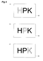
- Figs. 8 are views explaining a third mode of the laser processing method according to the first embodiment.
- the white circles indicate laser light condensing positions
- the black circles indicate already processed positions.
- laser light is condensed and irradiated to the processing region 91 and the non-processing region 92 of the processing object 90 so as to carry out a multi-point display of three alphabetical characters of "H,” "T,” and "V" to process the processing object 90.
- Fig. 8(a) shows a state of a laser light output from the spatial light modulator 20 where three holograms have been sequentially presented being, by the condensing optical system 30, irradiated to eight points of condensing positions a1 to a8 within the processing region 91, and irradiated to 20 points of condensing positions a9 to a28 within the non-processing region 92.
- a part of the incident light is condensed as a contribution light having a constant energy not less than a predetermined threshold X.
- a remaining part of the incident light that is, the incident light from which the part of laser light condensed to the condensing positions a1 to a8 has been excluded, which is a laser light unnecessary at the processing surface of the processing object 90
- a remaining part of the incident light that is, the incident light from which the part of laser light condensed to the condensing positions a1 to a8 has been excluded, which is a laser light unnecessary at the processing surface of the processing object 90
- the non-processing region 92 Since the non-contribution light having a weak energy less than the threshold X is condensed to the condensing positions a9 to a28 existing in the non-processing region 92, the non-processing region 92 is not processed even after condensing and irradiation of the non-contribution light.
- a total energy of an incident light is, for example, 13 GW/cm 2
- a part of the incident light is condensed to the processing region 91, and the rest is dispersed and condensed as a plurality of laser lights having a weak energy to the non-processing region 92.
- a laser light having a constant energy of, for example, 1 GW/cm 2 is condensed to each of the condensing positions a1 to a8 existing in the processing region 91.
- a remaining laser light that is, a laser light of 5 GW/cm 2 excluding, of 13 GW/cm 2 being a total energy of the incident light
- Fig. 8(b) shows a state of a laser light output from the spatial light modulator 20 where three holograms have been sequentially presented being, by the condensing optical system 30, irradiated to 12 points of condensing positions b1 to b 12 within the processing region 91, and irradiated to four points of condensing positions b13 to b 16 within the non-processing region 92.
- a part of the incident light is condensed as a contribution light having a constant energy not less than a predetermined threshold X.
- a remaining part of the incident light that is, the incident light from which the part of laser light condensed to the condensing positions b1 to b12 has been excluded, which is a laser light unnecessary at the processing surface of the processing object 90
- a remaining part of the incident light that is, the incident light from which the part of laser light condensed to the condensing positions b1 to b12 has been excluded, which is a laser light unnecessary at the processing surface of the processing object 90
- the non-processing region 92 Since the non-contribution light having a weak energy less than the threshold X is condensed to the condensing positions b13 to b16 existing in the non-processing region 92, the non-processing region 92 is not processed even after condensing and irradiation of the non-contribution light.
- a part of the incident light is condensed to the processing region 91, and the rest is dispersed and condensed as a plurality of laser lights having a weak energy to the non-processing region 92 in Fig. 8(b) .
- a laser light having a constant energy of, for example, 1 GW/cm 2 is condensed to each of the condensing positions b1 to b12 existing in the processing region 91.
- Fig. 8(c) shows a state of a laser light output from the spatial light modulator 20 where three holograms have been sequentially presented being, by the condensing optical system 30, irradiated to nine points of condensing positions c1 to c9 within the processing region 91, and irradiated to 16 points of condensing positions c10 to c25 within the non-processing region 92.
- a part of the incident light is condensed as a contribution light having a constant energy not less than a predetermined threshold X.
- a part of the processing region 91 to which the laser light has been condensed and irradiated is processed with a pattern of two oblique bars of the character "V" after the condensing and irradiation of the laser light.
- a remaining part of the incident light that is, the incident light from which the part of laser light condensed to the condensing positions c1 to c9 has been excluded, which is a laser light unnecessary at the processing surface of the processing object 90
- a remaining part of the incident light that is, the incident light from which the part of laser light condensed to the condensing positions c1 to c9 has been excluded, which is a laser light unnecessary at the processing surface of the processing object 90
- the non-processing region 92 Since the non-contribution light having a weak energy less than the threshold X is condensed to the condensing positions c10 to c25 existing in the non-processing region 92, the non-processing region 92 is not processed even after condensing and irradiation of the non-contribution light.
- a part of the incident light is condensed to the processing region 91, and the rest is dispersed and condensed as a plurality of laser lights having a weak energy to the non-processing region 92 in Fig. 8(c) .
- a laser light having a constant energy of, for example, 1 GW/cm 2 is condensed to each of the condensing positions c1 to c9 existing in the processing region 91.
- the third mode when the energy of an incident light is great, allows appropriately setting the size of a laser light irradiation energy at the respective condensing positions existing in the processing region 91, and is thus preferable.
- the energy of an incident light is great, by increasing the number of condensing positions (for example, b13 to b 16) existing in the non-processing region 92, the size of a laser light irradiation energy at the respective condensing positions existing in the processing region 91 can be appropriately maintained.
- Figs. 9 are views explaining a fourth mode of the laser processing method according to the first embodiment.
- the white circles indicate laser light condensing positions
- the black circles indicate already processed positions.
- laser light is condensed and irradiated to the processing region 91 and the non-processing region 92 of the processing object 90 so as to carry out a multi-point display of a single alphabetical character of "H" to process the processing object 90.
- a part of the character "H” is first processed, another part of the character “H” is then processed, and the remaining part of the character “H” is lastly processed.
- Fig. 9(a) shows a state of a laser light output from the spatial light modulator 20 being, by the condensing optical system 30, irradiated to six points of condensing positions d1 to d6 within the processing region 91, and irradiated to eight points of condensing positions d7 to d14 within the non-processing region 92.
- a part of the incident light is condensed as a contribution light having a constant energy not less than a predetermined threshold X.
- the processing region 91 is processed after condensing and irradiation of the laser light.
- a remaining part of the incident light that is, the incident light from which the part of laser light condensed to the condensing positions d1 to d6 has been excluded, which is a laser light unnecessary at the processing surface of the processing object 90
- the non-processing region 92 Since the non-contribution light having a weak energy less than the threshold X is condensed to the condensing positions d7 to d14 existing in the non-processing region 92, the non-processing region 92 is not processed even after condensing and irradiation of the non-contribution light.
- a total energy of an incident light is, for example, 8 GW/cm 2
- a part of the incident light is condensed to the processing region 91, and the rest is dispersed and condensed as a plurality of laser lights having a weak energy to the non-processing region 92.
- a laser light having a constant energy of, for example, 1 GW/cm 2 is condensed to each of the condensing positions d1 to d6 existing in the processing region 91.
- a remaining laser light that is, a laser light of 2 GW/cm 2 excluding, of 8 GW/cm 2 being a total energy of the incident light
- Fig. 9(b) shows a state of a laser light output from the spatial light modulator 20 being, by the condensing optical system 30, entirely irradiated to eight points of condensing positions e1 to e8 within the processing region 91.
- the entire part of the incident light is condensed as a contribution light having a constant energy not less than a predetermined threshold X. Since the laser light having an energy not less than the threshold X is condensed to the condensing positions e1 to e8 existing in the processing region 91, the processing region 91 is processed after condensing and irradiation of the laser light.
- a total energy of an incident light is assumed as, for example, 8 GW/cm 2
- the incident light is entirely condensed to the processing region 91 in Fig. 9(b) .
- a laser light having a constant energy of, for example, 1 GW/cm 2 is condensed to each of the condensing positions e1 to e8 existing in the processing region 91.
- Fig. 9(c) shows a state of a laser light output from the spatial light modulator 20 being, by the condensing optical system 30, irradiated to three points of condensing positions f1 to f3 within the processing region 91, and irradiated to 20 points of condensing positions f4 to f23 within the non-processing region 92.
- a part of the incident light is condensed as a contribution light having a constant energy not less than a predetermined threshold X.
- the processing region 91 is processed after condensing and irradiation of the laser light.
- a remaining part of the incident light that is, the incident light from which the part of laser light condensed to the condensing positions f1 to f3 has been excluded, which is a laser light unnecessary at the processing surface of the processing object 90
- the non-processing region 92 Since the non-contribution light having a weak energy less than the threshold X is condensed to the condensing positions f4 to f23 existing in the non-processing region 92, the non-processing region 92 is not processed even after condensing and irradiation of the non-contribution light.
- a part of the incident light is condensed to the processing region 91, and the rest is dispersed and condensed as a plurality of laser lights having a weak energy to the non-processing region 92 in Fig. 9(c) .
- a laser light having a constant energy of, for example, 1 GW/cm 2 is condensed to each of the condensing positions f1 to f3 existing in the processing region 91.
- Fig. 10 and Fig. 11 are views explaining a fifth mode of the laser processing method according to the first embodiment.
- Fig. 10 and Fig. 11 clearly show that the processing region 91 may be provided not only on the surface of an upper surface of the processing object 90 but also inside of the processing object 90.
- the control section 22 may, as shown in Fig. 10 , cause the spatial light modulator 20 to present a hologram via the drive section 21 so that the height H 1 of a condensing position g1 existing in the processing region 91 with reference to a bottom surface 93 of the processing object 90 and the height H 2 of a condensing position g2 existing in the non-processing region 92 with reference to the bottom surface 93 become equal to each other.
- control section 22 may, as shown in Fig. 11 , cause the spatial light modulator 20 to present a hologram via the drive section 21 so that the height H 1 of a condensing position g1 existing in the processing region 91 with reference to a bottom surface 93 of the processing object 90 and the height H 2 of a condensing position g2 existing in the non-processing region 92 with reference to the bottom surface 93 are different from each other. Also, in Fig. 10 and Fig.
- the condensing position g1 existing in the processing region 91 and the condensing position g2 existing in the non-processing region 92 are only displayed one each, but in actuality, the condensing positions g1 and g2 may be each in plural numbers as shown in Figs. 6 to Figs. 9 . Moreover, the matters other then the above are in common with the first mode.
- a laser light output from the spatial light modulator 20 where a predetermined hologram has been presented is, by the condensing optical system 30, in a part of the incident light, condensed as a contribution light having a constant energy not less than a predetermined threshold X at the condensing position g1 existing in the processing region 91, while condensed as a non-contribution light having an energy less than the threshold X at the condensing position g2 existing in the non-processing region 92.
- the processing region 91 is provided not only on the surface of an upper surface of the processing object 90 but also inside of the processing object 90, by treating an unnecessary light as a non-contribution light having an energy less than a predetermined threshold X so as not to contribute to processing, even when the number of condensing positions in the processing region varies, the energy of a contribution light can be maintained constant, and therefore, processing unevenness can be suppressed.
- Holograms can be created by the GS method, the ORA method, or the like as described above, but when the spatial light modulator 20 is caused to present the created respective holograms, and a laser light output after being phase-modulated by the spatial light modulator 20 is caused to be condensed to predetermined condensing positions by the condensing optical system 30, in actuality, there is a case where the energy of laser light at the respective condensing positions within the processing region 91 is not constant. In such a case, it is necessary to alter by feedback holograms created by the above-described method.
- Fig. 12 is a flowchart of a hologram alteration method in the first embodiment.
- the spatial light modulator 20 is caused to present the hologram, a laser light output after being phase-modulated by the spatial light modulator 20 is caused to be condensed to predetermined condensing positions by the condensing optical system 30 (step S21), and the energy of laser light at the respective condensing positions is measured by a CCD (Charge Coupled Device) (step S22). If the measured energy of laser light at the respective condensing positions is as desired (Yes in step S23), the process ends here.
- CCD Charge Coupled Device
- step S23 the energy I base of a reference point of any of the condensing positions of measurement is determined (step S24), the amplitude of a laser light that needs to be reproduced at the respective condensing positions in a desired pattern is changed in accordance therewith (step S25), and a computer-generated hologram is recreated (step S26).
- step S25 The energy of laser light at the respective condensing positions measured in step S22 is provided as In.
- step S26 based on the tone t n of the respective points after alteration, a computer-generated hologram is recreated by the GS method, the ORA method, or the like.
- Such a hologram alteration by feedback can be applied also to when intentionally making the laser light energy nonuniform at laser light condensing positions in the processing region 91 at each time of processing.
- this phrase "pattern having a constant area” connotes a "line.”
- the second embodiment is basically the same as the foregoing first embodiment except that the unit of condensing and processing is not a “dot” but a "pattern having a constant area,” a brief description will be given mainly of the difference from the first embodiment in the following.
- the overall configuration of the laser processing device 1 according to the second embodiment is almost the same as that shown in Fig. 1 . However, there is a difference in the function of the control section 22. More specifically, the control section 22 according to the second embodiment causes the spatial light modulator 20 to sequentially present a plurality of holograms.
- control section 22 when having made a phase-modulated laser light output from the spatial light modulator 20 where a plurality of holograms have been respectively presented be input to the condensing optical system 30, in a condensing region existing in the processing region 91 of a predetermined condensing region of the processing object 90, causes a part of the phase-modulated laser light to be condensed as a laser light (contribution light) having a constant energy not less than a predetermined threshold X.
- control section 22 in a condensing region existing in the non-processing region 92 of the predetermined condensing region of the processing object 90, causes a remaining part of the phase-modulated laser light to be condensed as a laser light (non-contribution light) having a weak energy less than the threshold X to thereby process the processing object 90.
- Figs. 13 are views for explaining the same.
- Fig. 13(a) shows a state of laser light being, in order to process the character "H,” irradiated to a condensing region (pattern h) having an area Y1 within the processing region 91.
- Fig. 13(b) shows a state of laser light being, in order to process the character "P," irradiated to a condensing region (pattern p) having an area Y2 within the processing region 91, and irradiated to a condensing region (pattern p1) having an area Y3 within the non-processing region 92.
- a part of the incident light is condensed as a contribution light having a constant energy not less than a predetermined threshold X.
- a part of the processing region 91 to which the laser light has been condensed and irradiated is processed with a pattern of the character "P" after the condensing and irradiation of the laser light.
- the condensing region (pattern p1) having an area Y3 existing in the non-processing region 92 a remaining part of the incident light (that is, the incident light from which the part of laser light condensed to the pattern p has been excluded, an unnecessary light) is condensed as a laser light having a weak energy less than the predetermined threshold X.
- Fig. 13(c) shows a state of laser light being, in order to process the character "K,” irradiated to a condensing region (pattern k) having an area Y4 within the processing region 91, and irradiated to a condensing region (pattern k1) having an area Y5 within the non-processing region 92.
- a part of the incident light is condensed as a contribution light having a constant energy not less than a predetermined threshold X.
- a part of the processing region 91 to which the laser light has been condensed and irradiated is processed with a pattern of the character "K" after the condensing and irradiation of the laser light.
- the condensing region (pattern k1) having an area Y5 existing in the non-processing region 92 a remaining part of the incident light (that is, the incident light from which the part of laser light condensed to the pattern k has been excluded, an unnecessary light) is condensed as a laser light having a weak energy less than the predetermined threshold X.
- Y1, Y2, and Y4 are examples of the area of a condensing region existing within the processing region 91, and the size relationship among these is, for example, Y1>Y2>Y4.
- the size relationship among Y1, Y2, and Y4 is paraphrased, it can be assumed in association with the first mode ( Figs. 6 ) of the first embodiment described above that, for example, the area Y1 is an area for 12 dots, the area Y2 is an area for 11 dots, and the area Y4 is an area for 10 dots.
- a laser light having a constant energy (1 GW/cm 2 ) not less than the threshold X is condensed to the pattern h for 12 dots (12 GW/cm 2 ).
- a laser light having a constant energy (1 GW/cm 2 ) not less than the threshold X is condensed to the pattern p for 11 dots (11 GW/cm 2 ), while an unnecessary light for one dot is condensed in the pattern p1 as a non-contribution light having a weak energy (0.250 GW/cm 2 ) less than the predetermined threshold X.
- a laser light having a constant energy (1 GW/cm 2 ) not less than the threshold X is condensed to the pattern k for 10 dots (10 GW/cm 2 ), while an unnecessary light for two dots is condensed in the pattern k1 as a non-contribution light having a weak energy (0.250 GW/cm 2 ) less than the predetermined threshold X. Since an unnecessary light twice as much as that in the pattern p 1 is condensed in the pattern k1, the area Y5 is twice as large as the area Y3. In addition, no unnecessary light is generated in the processing of the character "H," and the incident light is entirely condensed to the pattern has a contribution light.
- a laser light output from the spatial light modulator 20 where holograms corresponding to "H,” “P,” and “K,” respectively, have been sequentially presented is, by the condensing optical system 30, condensed in the condensing region (pattern h, p, k) existing in the processing region 91 as a contribution light having a constant energy not less than a predetermined threshold X, while at the condensing position (pattern p1, k1) existing in the non-processing region 92, condensed as a non-contribution light having an energy less than the threshold X.
- Example 1 two points of condensing positions in the processing region 91 and eight points of condensing positions in the non-processing region 92 are first provided ( Fig. 16(a) ), and four points of condensing positions in the processing region 91 and zero points of condensing positions in the non-processing region 92 are then provided ( Fig. 16(b) ).
- Fig. 17 is a table summarizing laser light energies at respective condensing positions in the comparative example. It can be understood that, in the comparative example, the total energy of incident light is approximately 4 GW/cm 2 , and the energy of laser light for processing differs between when the processing is performed at two points and when the processing is performed at four points (such as, for example, 2 GW/cm 2 and 1 GW/cm 2 in terms of point 1). Due to a change in light energy, uniform processing is difficult.
- Fig. 18 is a table summarizing laser light energies at respective condensing positions in Example 1.
- Example 1 the total energy of incident light is approximately 4 GW/cm 2 , and even when the number of condensing positions in the processing region 91 varies, since a remaining unnecessary light is appropriately treated in the non-processing region 92, the laser light energy at the respective condensing positions within the processing region 91 is almost constant (almost constant within a range of 0.990 GW/cm 2 to 1.020 GW/cm 2 ). In Fig. 16(a) , unnecessary lights for two condensing positions are generated as compared with Fig.
- Example 2 is carried out under all the same conditions as those of Example 1 described above, but there is a difference in that the unit of condensing and processing is not a "dot” but a "pattern having a constant area.” More specifically, in Example 2, as shown in Figs. 19 , first, the condensing region in the processing region 91 is provided as a linear pattern A having an area Y6, and the condensing region in the non-processing region 92 is provided as a pattern B having an area Y7 ( Fig. 19(a) ). Then, the condensing region in the processing region 91 is provided as a linear pattern C having an area Y8, and no condensing region is provided in the non-processing region 92 ( Fig.
- Y6 and Y8 are examples of the area of a condensing region existing within the processing region 91, and the size relationship between these is, for example, Y6 ⁇ Y8.
- the size relationship between Y6 and Y8 is paraphrased, it can be assumed in association with Example 1 described above that, for example, the area Y6 is an area for two dots, and the area Y8 is an area for four dots. In this case, unnecessary lights for two dots are generated in Fig. 19(a) as compared with Fig. 19(b) , but these are treated in the pattern B having an area Y7 in the non-processing region 92 as non-contribution lights each having a weak energy of approximately one-fourth.
- Fig. 20 is a table summarizing laser light energies in respective condensing regions in Example 2. It can be understood that, in Example 2, even when the area of a condensing region in the processing region 91 varies, since a remaining unnecessary light is appropriately treated in the non-processing region 92, the laser light energy in the respective condensing regions (pattern A and pattern C) within the processing region 91 is almost constant (an energy equivalent to one dot is 1.0 GW/cm 2 or 1.010 GW/cm 2 , which is almost constant).
- the laser light energy in a condensing region (pattern B) within the non-processing region 92 is less than a predetermined threshold X (an energy equivalent to one dot is 0.250 GW/cm 2 ) so as not to contribute to processing.
- a predetermined threshold X an energy equivalent to one dot is 0.250 GW/cm 2
- the area Y6 of the pattern A is an area for two dots
- a total energy of a laser light to be condensed to the pattern A is 2 GW/cm 2 .
- the area Y8 of the pattern C is an area for four dots, a total energy of a laser light to be condensed to the pattern C is 4.040 GW/cm 2 .
- the present invention provides a laser processing device and a laser processing method that allow maintaining the energy of laser light to be irradiated to a condensing position or condensing region existing in a processing region almost constant.
Landscapes
- Physics & Mathematics (AREA)
- Optics & Photonics (AREA)
- Engineering & Computer Science (AREA)
- Plasma & Fusion (AREA)
- Mechanical Engineering (AREA)
- General Physics & Mathematics (AREA)
- Holo Graphy (AREA)
- Laser Beam Processing (AREA)
Priority Applications (1)
| Application Number | Priority Date | Filing Date | Title |
|---|---|---|---|
| EP16185966.5A EP3138654B1 (fr) | 2008-08-26 | 2009-08-24 | Dispositif de traitement laser et procédé de traitement laser |
Applications Claiming Priority (2)
| Application Number | Priority Date | Filing Date | Title |
|---|---|---|---|
| JP2008216742 | 2008-08-26 | ||
| PCT/JP2009/064725 WO2010024218A1 (fr) | 2008-08-26 | 2009-08-24 | Dispositif et procédé de traitement au laser |
Related Child Applications (2)
| Application Number | Title | Priority Date | Filing Date |
|---|---|---|---|
| EP16185966.5A Division EP3138654B1 (fr) | 2008-08-26 | 2009-08-24 | Dispositif de traitement laser et procédé de traitement laser |
| EP16185966.5A Division-Into EP3138654B1 (fr) | 2008-08-26 | 2009-08-24 | Dispositif de traitement laser et procédé de traitement laser |
Publications (3)
| Publication Number | Publication Date |
|---|---|
| EP2335862A1 true EP2335862A1 (fr) | 2011-06-22 |
| EP2335862A4 EP2335862A4 (fr) | 2015-07-22 |
| EP2335862B1 EP2335862B1 (fr) | 2016-10-19 |
Family
ID=41721386
Family Applications (2)
| Application Number | Title | Priority Date | Filing Date |
|---|---|---|---|
| EP16185966.5A Active EP3138654B1 (fr) | 2008-08-26 | 2009-08-24 | Dispositif de traitement laser et procédé de traitement laser |
| EP09809869.2A Active EP2335862B1 (fr) | 2008-08-26 | 2009-08-24 | Dispositif et procédé de traitement au laser |
Family Applications Before (1)
| Application Number | Title | Priority Date | Filing Date |
|---|---|---|---|
| EP16185966.5A Active EP3138654B1 (fr) | 2008-08-26 | 2009-08-24 | Dispositif de traitement laser et procédé de traitement laser |
Country Status (6)
| Country | Link |
|---|---|
| US (1) | US8867113B2 (fr) |
| EP (2) | EP3138654B1 (fr) |
| JP (1) | JP5355576B2 (fr) |
| CN (1) | CN102137731B (fr) |
| ES (2) | ES2666229T3 (fr) |
| WO (1) | WO2010024218A1 (fr) |
Cited By (1)
| Publication number | Priority date | Publication date | Assignee | Title |
|---|---|---|---|---|
| US11351062B2 (en) | 2014-10-08 | 2022-06-07 | Universite Jean Monnet Saint Etienne | Device and method for cutting a cornea or crystalline lens |
Families Citing this family (10)
| Publication number | Priority date | Publication date | Assignee | Title |
|---|---|---|---|---|
| JP5802110B2 (ja) * | 2011-10-26 | 2015-10-28 | 浜松ホトニクス株式会社 | 光変調制御方法、制御プログラム、制御装置、及びレーザ光照射装置 |
| JP5789527B2 (ja) * | 2012-01-18 | 2015-10-07 | 株式会社アマダホールディングス | レーザ加工装置及びレーザ発振制御方法 |
| CN105116492A (zh) * | 2015-08-26 | 2015-12-02 | 成都秋雷科技有限责任公司 | 照明光控制方法 |
| JP6363680B2 (ja) * | 2016-11-16 | 2018-07-25 | ファナック株式会社 | レーザ装置 |
| GB2576029B (en) * | 2018-08-02 | 2021-03-03 | Envisics Ltd | Illumination system and method |
| JP7219589B2 (ja) * | 2018-10-30 | 2023-02-08 | 浜松ホトニクス株式会社 | レーザ加工装置 |
| KR20210081402A (ko) * | 2018-10-30 | 2021-07-01 | 하마마츠 포토닉스 가부시키가이샤 | 레이저 가공 헤드 및 레이저 가공 장치 |
| JP6934083B1 (ja) * | 2020-04-08 | 2021-09-08 | 浜松ホトニクス株式会社 | レーザ加工装置及びレーザ加工方法 |
| JP7488684B2 (ja) * | 2020-04-08 | 2024-05-22 | 浜松ホトニクス株式会社 | レーザ加工装置及びレーザ加工方法 |
| JP7387666B2 (ja) | 2021-03-15 | 2023-11-28 | 東レエンジニアリング株式会社 | チップ部品除去装置 |
Family Cites Families (8)
| Publication number | Priority date | Publication date | Assignee | Title |
|---|---|---|---|---|
| JP2723798B2 (ja) | 1994-04-28 | 1998-03-09 | 三菱電機株式会社 | レーザ転写加工装置 |
| SE9800665D0 (sv) * | 1998-03-02 | 1998-03-02 | Micronic Laser Systems Ab | Improved method for projection printing using a micromirror SLM |
| US6710292B2 (en) * | 2000-01-19 | 2004-03-23 | Hamamatsu Photonics K.K. | Laser machining device |
| JP2001272636A (ja) * | 2000-01-19 | 2001-10-05 | Hamamatsu Photonics Kk | レーザ加工装置 |
| JP2001228449A (ja) * | 2000-02-14 | 2001-08-24 | Hamamatsu Photonics Kk | レーザ集光装置及びレーザ加工装置 |
| JP2004122233A (ja) * | 2000-08-28 | 2004-04-22 | Sumitomo Heavy Ind Ltd | レーザマーキング装置、マーキング方法及びマーキングされた光学部材 |
| DE10219388A1 (de) * | 2002-04-30 | 2003-11-20 | Siemens Ag | Verfahren zur Erzeugung einer Grabenstruktur in einem Polymer-Substrat |
| JP4647965B2 (ja) | 2004-10-22 | 2011-03-09 | 株式会社リコー | レーザ加工方法及びレーザ加工装置及びにこれよって作製された構造体 |
-
2009
- 2009-08-24 CN CN200980133930.1A patent/CN102137731B/zh active Active
- 2009-08-24 US US13/060,614 patent/US8867113B2/en active Active
- 2009-08-24 ES ES16185966.5T patent/ES2666229T3/es active Active
- 2009-08-24 JP JP2010526695A patent/JP5355576B2/ja active Active
- 2009-08-24 EP EP16185966.5A patent/EP3138654B1/fr active Active
- 2009-08-24 ES ES09809869.2T patent/ES2608464T3/es active Active
- 2009-08-24 WO PCT/JP2009/064725 patent/WO2010024218A1/fr active Application Filing
- 2009-08-24 EP EP09809869.2A patent/EP2335862B1/fr active Active
Non-Patent Citations (1)
| Title |
|---|
| See references of WO2010024218A1 * |
Cited By (1)
| Publication number | Priority date | Publication date | Assignee | Title |
|---|---|---|---|---|
| US11351062B2 (en) | 2014-10-08 | 2022-06-07 | Universite Jean Monnet Saint Etienne | Device and method for cutting a cornea or crystalline lens |
Also Published As
| Publication number | Publication date |
|---|---|
| ES2608464T3 (es) | 2017-04-11 |
| ES2666229T3 (es) | 2018-05-03 |
| JP5355576B2 (ja) | 2013-11-27 |
| US20110181929A1 (en) | 2011-07-28 |
| EP3138654B1 (fr) | 2018-03-14 |
| EP3138654A1 (fr) | 2017-03-08 |
| CN102137731B (zh) | 2014-01-01 |
| CN102137731A (zh) | 2011-07-27 |
| EP2335862A4 (fr) | 2015-07-22 |
| EP2335862B1 (fr) | 2016-10-19 |
| JPWO2010024218A1 (ja) | 2012-01-26 |
| US8867113B2 (en) | 2014-10-21 |
| WO2010024218A1 (fr) | 2010-03-04 |
Similar Documents
| Publication | Publication Date | Title |
|---|---|---|
| EP2335862B1 (fr) | Dispositif et procédé de traitement au laser | |
| US8941903B2 (en) | Laser emitting apparatus using a basic hologram and a focusing hologram | |
| CN101618637B (zh) | 激光加工装置和激光加工方法 | |
| US8324529B2 (en) | Laser machining device with a converged laser beam and laser machining method | |
| KR101605219B1 (ko) | 광 제어 장치 및 광 제어 방법 | |
| WO2016087393A1 (fr) | Système et procédé de contraste de phase généralisé à longueurs d'onde multiples | |
| KR101577096B1 (ko) | 광 제어 장치 및 광 제어 방법 | |
| EP1630588B1 (fr) | Methode de formation d'un motif optique, système de formation d'un motif optique, et d'une pincette optique | |
| JP5592457B2 (ja) | レーザ加工装置,レーザ加工方法,レーザ照射装置およびレーザ照射方法 | |
| JP5410043B2 (ja) | 光制御装置および光制御方法 | |
| WO2016174262A1 (fr) | Dispositif de projection de lumière 3d |
Legal Events
| Date | Code | Title | Description |
|---|---|---|---|
| PUAI | Public reference made under article 153(3) epc to a published international application that has entered the european phase |
Free format text: ORIGINAL CODE: 0009012 |
|
| 17P | Request for examination filed |
Effective date: 20110225 |
|
| AK | Designated contracting states |
Kind code of ref document: A1 Designated state(s): AT BE BG CH CY CZ DE DK EE ES FI FR GB GR HR HU IE IS IT LI LT LU LV MC MK MT NL NO PL PT RO SE SI SK SM TR |
|
| AX | Request for extension of the european patent |
Extension state: AL BA RS |
|
| DAX | Request for extension of the european patent (deleted) | ||
| RA4 | Supplementary search report drawn up and despatched (corrected) |
Effective date: 20150619 |
|
| RIC1 | Information provided on ipc code assigned before grant |
Ipc: B23K 26/06 20140101ALI20150615BHEP Ipc: B23K 26/067 20060101ALI20150615BHEP Ipc: B23K 26/073 20060101ALI20150615BHEP Ipc: B23K 26/00 20140101AFI20150615BHEP Ipc: B41M 5/26 20060101ALI20150615BHEP Ipc: G02F 1/061 20060101ALI20150615BHEP |
|
| GRAP | Despatch of communication of intention to grant a patent |
Free format text: ORIGINAL CODE: EPIDOSNIGR1 |
|
| RIC1 | Information provided on ipc code assigned before grant |
Ipc: B23K 26/00 20140101AFI20160415BHEP Ipc: G02F 1/061 20060101ALI20160415BHEP Ipc: B23K 26/06 20060101ALI20160415BHEP Ipc: B23K 26/073 20060101ALI20160415BHEP Ipc: B23K 26/067 20060101ALI20160415BHEP Ipc: B41M 5/26 20060101ALI20160415BHEP |
|
| INTG | Intention to grant announced |
Effective date: 20160506 |
|
| GRAS | Grant fee paid |
Free format text: ORIGINAL CODE: EPIDOSNIGR3 |
|
| GRAA | (expected) grant |
Free format text: ORIGINAL CODE: 0009210 |
|
| AK | Designated contracting states |
Kind code of ref document: B1 Designated state(s): AT BE BG CH CY CZ DE DK EE ES FI FR GB GR HR HU IE IS IT LI LT LU LV MC MK MT NL NO PL PT RO SE SI SK SM TR |
|
| REG | Reference to a national code |
Ref country code: GB Ref legal event code: FG4D |
|
| REG | Reference to a national code |
Ref country code: CH Ref legal event code: EP |
|
| REG | Reference to a national code |
Ref country code: AT Ref legal event code: REF Ref document number: 837910 Country of ref document: AT Kind code of ref document: T Effective date: 20161115 |
|
| REG | Reference to a national code |
Ref country code: IE Ref legal event code: FG4D |
|
| REG | Reference to a national code |
Ref country code: DE Ref legal event code: R096 Ref document number: 602009041871 Country of ref document: DE |
|
| REG | Reference to a national code |
Ref country code: NL Ref legal event code: MP Effective date: 20161019 |
|
| REG | Reference to a national code |
Ref country code: LT Ref legal event code: MG4D |
|
| PG25 | Lapsed in a contracting state [announced via postgrant information from national office to epo] |
Ref country code: LV Free format text: LAPSE BECAUSE OF FAILURE TO SUBMIT A TRANSLATION OF THE DESCRIPTION OR TO PAY THE FEE WITHIN THE PRESCRIBED TIME-LIMIT Effective date: 20161019 |
|
| REG | Reference to a national code |
Ref country code: AT Ref legal event code: MK05 Ref document number: 837910 Country of ref document: AT Kind code of ref document: T Effective date: 20161019 |
|
| REG | Reference to a national code |
Ref country code: ES Ref legal event code: FG2A Ref document number: 2608464 Country of ref document: ES Kind code of ref document: T3 Effective date: 20170411 |
|
| PG25 | Lapsed in a contracting state [announced via postgrant information from national office to epo] |
Ref country code: GR Free format text: LAPSE BECAUSE OF FAILURE TO SUBMIT A TRANSLATION OF THE DESCRIPTION OR TO PAY THE FEE WITHIN THE PRESCRIBED TIME-LIMIT Effective date: 20170120 Ref country code: NO Free format text: LAPSE BECAUSE OF FAILURE TO SUBMIT A TRANSLATION OF THE DESCRIPTION OR TO PAY THE FEE WITHIN THE PRESCRIBED TIME-LIMIT Effective date: 20170119 Ref country code: LT Free format text: LAPSE BECAUSE OF FAILURE TO SUBMIT A TRANSLATION OF THE DESCRIPTION OR TO PAY THE FEE WITHIN THE PRESCRIBED TIME-LIMIT Effective date: 20161019 Ref country code: SE Free format text: LAPSE BECAUSE OF FAILURE TO SUBMIT A TRANSLATION OF THE DESCRIPTION OR TO PAY THE FEE WITHIN THE PRESCRIBED TIME-LIMIT Effective date: 20161019 |
|
| PG25 | Lapsed in a contracting state [announced via postgrant information from national office to epo] |
Ref country code: PL Free format text: LAPSE BECAUSE OF FAILURE TO SUBMIT A TRANSLATION OF THE DESCRIPTION OR TO PAY THE FEE WITHIN THE PRESCRIBED TIME-LIMIT Effective date: 20161019 Ref country code: FI Free format text: LAPSE BECAUSE OF FAILURE TO SUBMIT A TRANSLATION OF THE DESCRIPTION OR TO PAY THE FEE WITHIN THE PRESCRIBED TIME-LIMIT Effective date: 20161019 Ref country code: NL Free format text: LAPSE BECAUSE OF FAILURE TO SUBMIT A TRANSLATION OF THE DESCRIPTION OR TO PAY THE FEE WITHIN THE PRESCRIBED TIME-LIMIT Effective date: 20161019 Ref country code: BE Free format text: LAPSE BECAUSE OF FAILURE TO SUBMIT A TRANSLATION OF THE DESCRIPTION OR TO PAY THE FEE WITHIN THE PRESCRIBED TIME-LIMIT Effective date: 20161019 Ref country code: PT Free format text: LAPSE BECAUSE OF FAILURE TO SUBMIT A TRANSLATION OF THE DESCRIPTION OR TO PAY THE FEE WITHIN THE PRESCRIBED TIME-LIMIT Effective date: 20170220 Ref country code: AT Free format text: LAPSE BECAUSE OF FAILURE TO SUBMIT A TRANSLATION OF THE DESCRIPTION OR TO PAY THE FEE WITHIN THE PRESCRIBED TIME-LIMIT Effective date: 20161019 Ref country code: IS Free format text: LAPSE BECAUSE OF FAILURE TO SUBMIT A TRANSLATION OF THE DESCRIPTION OR TO PAY THE FEE WITHIN THE PRESCRIBED TIME-LIMIT Effective date: 20170219 Ref country code: HR Free format text: LAPSE BECAUSE OF FAILURE TO SUBMIT A TRANSLATION OF THE DESCRIPTION OR TO PAY THE FEE WITHIN THE PRESCRIBED TIME-LIMIT Effective date: 20161019 |
|
| REG | Reference to a national code |
Ref country code: DE Ref legal event code: R097 Ref document number: 602009041871 Country of ref document: DE |
|
| PG25 | Lapsed in a contracting state [announced via postgrant information from national office to epo] |
Ref country code: CZ Free format text: LAPSE BECAUSE OF FAILURE TO SUBMIT A TRANSLATION OF THE DESCRIPTION OR TO PAY THE FEE WITHIN THE PRESCRIBED TIME-LIMIT Effective date: 20161019 Ref country code: RO Free format text: LAPSE BECAUSE OF FAILURE TO SUBMIT A TRANSLATION OF THE DESCRIPTION OR TO PAY THE FEE WITHIN THE PRESCRIBED TIME-LIMIT Effective date: 20161019 Ref country code: DK Free format text: LAPSE BECAUSE OF FAILURE TO SUBMIT A TRANSLATION OF THE DESCRIPTION OR TO PAY THE FEE WITHIN THE PRESCRIBED TIME-LIMIT Effective date: 20161019 Ref country code: SK Free format text: LAPSE BECAUSE OF FAILURE TO SUBMIT A TRANSLATION OF THE DESCRIPTION OR TO PAY THE FEE WITHIN THE PRESCRIBED TIME-LIMIT Effective date: 20161019 Ref country code: EE Free format text: LAPSE BECAUSE OF FAILURE TO SUBMIT A TRANSLATION OF THE DESCRIPTION OR TO PAY THE FEE WITHIN THE PRESCRIBED TIME-LIMIT Effective date: 20161019 |
|
| PLBE | No opposition filed within time limit |
Free format text: ORIGINAL CODE: 0009261 |
|
| STAA | Information on the status of an ep patent application or granted ep patent |
Free format text: STATUS: NO OPPOSITION FILED WITHIN TIME LIMIT |
|
| PG25 | Lapsed in a contracting state [announced via postgrant information from national office to epo] |
Ref country code: SM Free format text: LAPSE BECAUSE OF FAILURE TO SUBMIT A TRANSLATION OF THE DESCRIPTION OR TO PAY THE FEE WITHIN THE PRESCRIBED TIME-LIMIT Effective date: 20161019 Ref country code: IT Free format text: LAPSE BECAUSE OF FAILURE TO SUBMIT A TRANSLATION OF THE DESCRIPTION OR TO PAY THE FEE WITHIN THE PRESCRIBED TIME-LIMIT Effective date: 20161019 Ref country code: BG Free format text: LAPSE BECAUSE OF FAILURE TO SUBMIT A TRANSLATION OF THE DESCRIPTION OR TO PAY THE FEE WITHIN THE PRESCRIBED TIME-LIMIT Effective date: 20170119 |
|
| 26N | No opposition filed |
Effective date: 20170720 |
|
| PG25 | Lapsed in a contracting state [announced via postgrant information from national office to epo] |
Ref country code: SI Free format text: LAPSE BECAUSE OF FAILURE TO SUBMIT A TRANSLATION OF THE DESCRIPTION OR TO PAY THE FEE WITHIN THE PRESCRIBED TIME-LIMIT Effective date: 20161019 |
|
| REG | Reference to a national code |
Ref country code: CH Ref legal event code: PL |
|
| PG25 | Lapsed in a contracting state [announced via postgrant information from national office to epo] |
Ref country code: MC Free format text: LAPSE BECAUSE OF FAILURE TO SUBMIT A TRANSLATION OF THE DESCRIPTION OR TO PAY THE FEE WITHIN THE PRESCRIBED TIME-LIMIT Effective date: 20161019 |
|
| PG25 | Lapsed in a contracting state [announced via postgrant information from national office to epo] |
Ref country code: CH Free format text: LAPSE BECAUSE OF NON-PAYMENT OF DUE FEES Effective date: 20170831 Ref country code: LI Free format text: LAPSE BECAUSE OF NON-PAYMENT OF DUE FEES Effective date: 20170831 |
|
| REG | Reference to a national code |
Ref country code: FR Ref legal event code: ST Effective date: 20180430 |
|
| REG | Reference to a national code |
Ref country code: IE Ref legal event code: MM4A |
|
| PG25 | Lapsed in a contracting state [announced via postgrant information from national office to epo] |
Ref country code: LU Free format text: LAPSE BECAUSE OF NON-PAYMENT OF DUE FEES Effective date: 20170824 |
|
| PG25 | Lapsed in a contracting state [announced via postgrant information from national office to epo] |
Ref country code: IE Free format text: LAPSE BECAUSE OF NON-PAYMENT OF DUE FEES Effective date: 20170824 |
|
| PG25 | Lapsed in a contracting state [announced via postgrant information from national office to epo] |
Ref country code: FR Free format text: LAPSE BECAUSE OF NON-PAYMENT OF DUE FEES Effective date: 20170831 |
|
| PG25 | Lapsed in a contracting state [announced via postgrant information from national office to epo] |
Ref country code: MT Free format text: LAPSE BECAUSE OF NON-PAYMENT OF DUE FEES Effective date: 20170824 |
|
| PG25 | Lapsed in a contracting state [announced via postgrant information from national office to epo] |
Ref country code: HU Free format text: LAPSE BECAUSE OF FAILURE TO SUBMIT A TRANSLATION OF THE DESCRIPTION OR TO PAY THE FEE WITHIN THE PRESCRIBED TIME-LIMIT; INVALID AB INITIO Effective date: 20090824 |
|
| PG25 | Lapsed in a contracting state [announced via postgrant information from national office to epo] |
Ref country code: CY Free format text: LAPSE BECAUSE OF NON-PAYMENT OF DUE FEES Effective date: 20161019 |
|
| PG25 | Lapsed in a contracting state [announced via postgrant information from national office to epo] |
Ref country code: MK Free format text: LAPSE BECAUSE OF FAILURE TO SUBMIT A TRANSLATION OF THE DESCRIPTION OR TO PAY THE FEE WITHIN THE PRESCRIBED TIME-LIMIT Effective date: 20161019 |
|
| PG25 | Lapsed in a contracting state [announced via postgrant information from national office to epo] |
Ref country code: TR Free format text: LAPSE BECAUSE OF FAILURE TO SUBMIT A TRANSLATION OF THE DESCRIPTION OR TO PAY THE FEE WITHIN THE PRESCRIBED TIME-LIMIT Effective date: 20161019 |
|
| P01 | Opt-out of the competence of the unified patent court (upc) registered |
Effective date: 20230509 |
|
| PGFP | Annual fee paid to national office [announced via postgrant information from national office to epo] |
Ref country code: GB Payment date: 20230706 Year of fee payment: 15 Ref country code: ES Payment date: 20230901 Year of fee payment: 15 |
|
| PGFP | Annual fee paid to national office [announced via postgrant information from national office to epo] |
Ref country code: DE Payment date: 20230627 Year of fee payment: 15 |