EP2335797A1 - Ceramic honeycomb structure and process for producing the same - Google Patents
Ceramic honeycomb structure and process for producing the same Download PDFInfo
- Publication number
- EP2335797A1 EP2335797A1 EP09802754A EP09802754A EP2335797A1 EP 2335797 A1 EP2335797 A1 EP 2335797A1 EP 09802754 A EP09802754 A EP 09802754A EP 09802754 A EP09802754 A EP 09802754A EP 2335797 A1 EP2335797 A1 EP 2335797A1
- Authority
- EP
- European Patent Office
- Prior art keywords
- ceramic honeycomb
- pore
- less
- volume
- honeycomb structure
- Prior art date
- Legal status (The legal status is an assumption and is not a legal conclusion. Google has not performed a legal analysis and makes no representation as to the accuracy of the status listed.)
- Granted
Links
Images


Classifications
-
- B—PERFORMING OPERATIONS; TRANSPORTING
- B01—PHYSICAL OR CHEMICAL PROCESSES OR APPARATUS IN GENERAL
- B01D—SEPARATION
- B01D39/00—Filtering material for liquid or gaseous fluids
- B01D39/14—Other self-supporting filtering material ; Other filtering material
- B01D39/20—Other self-supporting filtering material ; Other filtering material of inorganic material, e.g. asbestos paper, metallic filtering material of non-woven wires
-
- F—MECHANICAL ENGINEERING; LIGHTING; HEATING; WEAPONS; BLASTING
- F01—MACHINES OR ENGINES IN GENERAL; ENGINE PLANTS IN GENERAL; STEAM ENGINES
- F01N—GAS-FLOW SILENCERS OR EXHAUST APPARATUS FOR MACHINES OR ENGINES IN GENERAL; GAS-FLOW SILENCERS OR EXHAUST APPARATUS FOR INTERNAL-COMBUSTION ENGINES
- F01N3/00—Exhaust or silencing apparatus having means for purifying, rendering innocuous, or otherwise treating exhaust
- F01N3/02—Exhaust or silencing apparatus having means for purifying, rendering innocuous, or otherwise treating exhaust for cooling, or for removing solid constituents of, exhaust
- F01N3/021—Exhaust or silencing apparatus having means for purifying, rendering innocuous, or otherwise treating exhaust for cooling, or for removing solid constituents of, exhaust by means of filters
- F01N3/022—Exhaust or silencing apparatus having means for purifying, rendering innocuous, or otherwise treating exhaust for cooling, or for removing solid constituents of, exhaust by means of filters characterised by specially adapted filtering structure, e.g. honeycomb, mesh or fibrous
- F01N3/0222—Exhaust or silencing apparatus having means for purifying, rendering innocuous, or otherwise treating exhaust for cooling, or for removing solid constituents of, exhaust by means of filters characterised by specially adapted filtering structure, e.g. honeycomb, mesh or fibrous the structure being monolithic, e.g. honeycombs
-
- B—PERFORMING OPERATIONS; TRANSPORTING
- B01—PHYSICAL OR CHEMICAL PROCESSES OR APPARATUS IN GENERAL
- B01D—SEPARATION
- B01D46/00—Filters or filtering processes specially modified for separating dispersed particles from gases or vapours
- B01D46/24—Particle separators, e.g. dust precipitators, using rigid hollow filter bodies
- B01D46/2403—Particle separators, e.g. dust precipitators, using rigid hollow filter bodies characterised by the physical shape or structure of the filtering element
- B01D46/2418—Honeycomb filters
- B01D46/2425—Honeycomb filters characterized by parameters related to the physical properties of the honeycomb structure material
-
- B—PERFORMING OPERATIONS; TRANSPORTING
- B01—PHYSICAL OR CHEMICAL PROCESSES OR APPARATUS IN GENERAL
- B01D—SEPARATION
- B01D46/00—Filters or filtering processes specially modified for separating dispersed particles from gases or vapours
- B01D46/24—Particle separators, e.g. dust precipitators, using rigid hollow filter bodies
- B01D46/2403—Particle separators, e.g. dust precipitators, using rigid hollow filter bodies characterised by the physical shape or structure of the filtering element
- B01D46/2418—Honeycomb filters
- B01D46/2425—Honeycomb filters characterized by parameters related to the physical properties of the honeycomb structure material
- B01D46/2429—Honeycomb filters characterized by parameters related to the physical properties of the honeycomb structure material of the honeycomb walls or cells
-
- B—PERFORMING OPERATIONS; TRANSPORTING
- B01—PHYSICAL OR CHEMICAL PROCESSES OR APPARATUS IN GENERAL
- B01D—SEPARATION
- B01D46/00—Filters or filtering processes specially modified for separating dispersed particles from gases or vapours
- B01D46/24—Particle separators, e.g. dust precipitators, using rigid hollow filter bodies
- B01D46/2403—Particle separators, e.g. dust precipitators, using rigid hollow filter bodies characterised by the physical shape or structure of the filtering element
- B01D46/2418—Honeycomb filters
- B01D46/2425—Honeycomb filters characterized by parameters related to the physical properties of the honeycomb structure material
- B01D46/24491—Porosity
-
- B—PERFORMING OPERATIONS; TRANSPORTING
- B01—PHYSICAL OR CHEMICAL PROCESSES OR APPARATUS IN GENERAL
- B01D—SEPARATION
- B01D46/00—Filters or filtering processes specially modified for separating dispersed particles from gases or vapours
- B01D46/24—Particle separators, e.g. dust precipitators, using rigid hollow filter bodies
- B01D46/2403—Particle separators, e.g. dust precipitators, using rigid hollow filter bodies characterised by the physical shape or structure of the filtering element
- B01D46/2418—Honeycomb filters
- B01D46/2425—Honeycomb filters characterized by parameters related to the physical properties of the honeycomb structure material
- B01D46/24492—Pore diameter
-
- B—PERFORMING OPERATIONS; TRANSPORTING
- B01—PHYSICAL OR CHEMICAL PROCESSES OR APPARATUS IN GENERAL
- B01D—SEPARATION
- B01D46/00—Filters or filtering processes specially modified for separating dispersed particles from gases or vapours
- B01D46/24—Particle separators, e.g. dust precipitators, using rigid hollow filter bodies
- B01D46/2403—Particle separators, e.g. dust precipitators, using rigid hollow filter bodies characterised by the physical shape or structure of the filtering element
- B01D46/2418—Honeycomb filters
- B01D46/2425—Honeycomb filters characterized by parameters related to the physical properties of the honeycomb structure material
- B01D46/24494—Thermal expansion coefficient, heat capacity or thermal conductivity
-
- B—PERFORMING OPERATIONS; TRANSPORTING
- B01—PHYSICAL OR CHEMICAL PROCESSES OR APPARATUS IN GENERAL
- B01D—SEPARATION
- B01D46/00—Filters or filtering processes specially modified for separating dispersed particles from gases or vapours
- B01D46/24—Particle separators, e.g. dust precipitators, using rigid hollow filter bodies
- B01D46/2403—Particle separators, e.g. dust precipitators, using rigid hollow filter bodies characterised by the physical shape or structure of the filtering element
- B01D46/2418—Honeycomb filters
- B01D46/2451—Honeycomb filters characterized by the geometrical structure, shape, pattern or configuration or parameters related to the geometry of the structure
- B01D46/247—Honeycomb filters characterized by the geometrical structure, shape, pattern or configuration or parameters related to the geometry of the structure of the cells
-
- B—PERFORMING OPERATIONS; TRANSPORTING
- B01—PHYSICAL OR CHEMICAL PROCESSES OR APPARATUS IN GENERAL
- B01D—SEPARATION
- B01D46/00—Filters or filtering processes specially modified for separating dispersed particles from gases or vapours
- B01D46/24—Particle separators, e.g. dust precipitators, using rigid hollow filter bodies
- B01D46/2403—Particle separators, e.g. dust precipitators, using rigid hollow filter bodies characterised by the physical shape or structure of the filtering element
- B01D46/2418—Honeycomb filters
- B01D46/2451—Honeycomb filters characterized by the geometrical structure, shape, pattern or configuration or parameters related to the geometry of the structure
- B01D46/2474—Honeycomb filters characterized by the geometrical structure, shape, pattern or configuration or parameters related to the geometry of the structure of the walls along the length of the honeycomb
-
- B—PERFORMING OPERATIONS; TRANSPORTING
- B01—PHYSICAL OR CHEMICAL PROCESSES OR APPARATUS IN GENERAL
- B01D—SEPARATION
- B01D46/00—Filters or filtering processes specially modified for separating dispersed particles from gases or vapours
- B01D46/24—Particle separators, e.g. dust precipitators, using rigid hollow filter bodies
- B01D46/2403—Particle separators, e.g. dust precipitators, using rigid hollow filter bodies characterised by the physical shape or structure of the filtering element
- B01D46/2418—Honeycomb filters
- B01D46/2451—Honeycomb filters characterized by the geometrical structure, shape, pattern or configuration or parameters related to the geometry of the structure
- B01D46/2482—Thickness, height, width, length or diameter
-
- B—PERFORMING OPERATIONS; TRANSPORTING
- B01—PHYSICAL OR CHEMICAL PROCESSES OR APPARATUS IN GENERAL
- B01D—SEPARATION
- B01D46/00—Filters or filtering processes specially modified for separating dispersed particles from gases or vapours
- B01D46/24—Particle separators, e.g. dust precipitators, using rigid hollow filter bodies
- B01D46/2403—Particle separators, e.g. dust precipitators, using rigid hollow filter bodies characterised by the physical shape or structure of the filtering element
- B01D46/2418—Honeycomb filters
- B01D46/2451—Honeycomb filters characterized by the geometrical structure, shape, pattern or configuration or parameters related to the geometry of the structure
- B01D46/2484—Cell density, area or aspect ratio
-
- C—CHEMISTRY; METALLURGY
- C04—CEMENTS; CONCRETE; ARTIFICIAL STONE; CERAMICS; REFRACTORIES
- C04B—LIME, MAGNESIA; SLAG; CEMENTS; COMPOSITIONS THEREOF, e.g. MORTARS, CONCRETE OR LIKE BUILDING MATERIALS; ARTIFICIAL STONE; CERAMICS; REFRACTORIES; TREATMENT OF NATURAL STONE
- C04B35/00—Shaped ceramic products characterised by their composition; Ceramics compositions; Processing powders of inorganic compounds preparatory to the manufacturing of ceramic products
- C04B35/01—Shaped ceramic products characterised by their composition; Ceramics compositions; Processing powders of inorganic compounds preparatory to the manufacturing of ceramic products based on oxide ceramics
- C04B35/16—Shaped ceramic products characterised by their composition; Ceramics compositions; Processing powders of inorganic compounds preparatory to the manufacturing of ceramic products based on oxide ceramics based on silicates other than clay
- C04B35/18—Shaped ceramic products characterised by their composition; Ceramics compositions; Processing powders of inorganic compounds preparatory to the manufacturing of ceramic products based on oxide ceramics based on silicates other than clay rich in aluminium oxide
- C04B35/195—Alkaline earth aluminosilicates, e.g. cordierite or anorthite
-
- C—CHEMISTRY; METALLURGY
- C04—CEMENTS; CONCRETE; ARTIFICIAL STONE; CERAMICS; REFRACTORIES
- C04B—LIME, MAGNESIA; SLAG; CEMENTS; COMPOSITIONS THEREOF, e.g. MORTARS, CONCRETE OR LIKE BUILDING MATERIALS; ARTIFICIAL STONE; CERAMICS; REFRACTORIES; TREATMENT OF NATURAL STONE
- C04B38/00—Porous mortars, concrete, artificial stone or ceramic ware; Preparation thereof
-
- C—CHEMISTRY; METALLURGY
- C04—CEMENTS; CONCRETE; ARTIFICIAL STONE; CERAMICS; REFRACTORIES
- C04B—LIME, MAGNESIA; SLAG; CEMENTS; COMPOSITIONS THEREOF, e.g. MORTARS, CONCRETE OR LIKE BUILDING MATERIALS; ARTIFICIAL STONE; CERAMICS; REFRACTORIES; TREATMENT OF NATURAL STONE
- C04B38/00—Porous mortars, concrete, artificial stone or ceramic ware; Preparation thereof
- C04B38/0006—Honeycomb structures
- C04B38/0009—Honeycomb structures characterised by features relating to the cell walls, e.g. wall thickness or distribution of pores in the walls
-
- F—MECHANICAL ENGINEERING; LIGHTING; HEATING; WEAPONS; BLASTING
- F01—MACHINES OR ENGINES IN GENERAL; ENGINE PLANTS IN GENERAL; STEAM ENGINES
- F01N—GAS-FLOW SILENCERS OR EXHAUST APPARATUS FOR MACHINES OR ENGINES IN GENERAL; GAS-FLOW SILENCERS OR EXHAUST APPARATUS FOR INTERNAL-COMBUSTION ENGINES
- F01N3/00—Exhaust or silencing apparatus having means for purifying, rendering innocuous, or otherwise treating exhaust
- F01N3/02—Exhaust or silencing apparatus having means for purifying, rendering innocuous, or otherwise treating exhaust for cooling, or for removing solid constituents of, exhaust
-
- C—CHEMISTRY; METALLURGY
- C04—CEMENTS; CONCRETE; ARTIFICIAL STONE; CERAMICS; REFRACTORIES
- C04B—LIME, MAGNESIA; SLAG; CEMENTS; COMPOSITIONS THEREOF, e.g. MORTARS, CONCRETE OR LIKE BUILDING MATERIALS; ARTIFICIAL STONE; CERAMICS; REFRACTORIES; TREATMENT OF NATURAL STONE
- C04B2111/00—Mortars, concrete or artificial stone or mixtures to prepare them, characterised by specific function, property or use
- C04B2111/00474—Uses not provided for elsewhere in C04B2111/00
- C04B2111/00793—Uses not provided for elsewhere in C04B2111/00 as filters or diaphragms
-
- C—CHEMISTRY; METALLURGY
- C04—CEMENTS; CONCRETE; ARTIFICIAL STONE; CERAMICS; REFRACTORIES
- C04B—LIME, MAGNESIA; SLAG; CEMENTS; COMPOSITIONS THEREOF, e.g. MORTARS, CONCRETE OR LIKE BUILDING MATERIALS; ARTIFICIAL STONE; CERAMICS; REFRACTORIES; TREATMENT OF NATURAL STONE
- C04B2111/00—Mortars, concrete or artificial stone or mixtures to prepare them, characterised by specific function, property or use
- C04B2111/00474—Uses not provided for elsewhere in C04B2111/00
- C04B2111/0081—Uses not provided for elsewhere in C04B2111/00 as catalysts or catalyst carriers
-
- C—CHEMISTRY; METALLURGY
- C04—CEMENTS; CONCRETE; ARTIFICIAL STONE; CERAMICS; REFRACTORIES
- C04B—LIME, MAGNESIA; SLAG; CEMENTS; COMPOSITIONS THEREOF, e.g. MORTARS, CONCRETE OR LIKE BUILDING MATERIALS; ARTIFICIAL STONE; CERAMICS; REFRACTORIES; TREATMENT OF NATURAL STONE
- C04B2235/00—Aspects relating to ceramic starting mixtures or sintered ceramic products
- C04B2235/02—Composition of constituents of the starting material or of secondary phases of the final product
- C04B2235/30—Constituents and secondary phases not being of a fibrous nature
- C04B2235/32—Metal oxides, mixed metal oxides, or oxide-forming salts thereof, e.g. carbonates, nitrates, (oxy)hydroxides, chlorides
- C04B2235/3205—Alkaline earth oxides or oxide forming salts thereof, e.g. beryllium oxide
- C04B2235/3206—Magnesium oxides or oxide-forming salts thereof
-
- C—CHEMISTRY; METALLURGY
- C04—CEMENTS; CONCRETE; ARTIFICIAL STONE; CERAMICS; REFRACTORIES
- C04B—LIME, MAGNESIA; SLAG; CEMENTS; COMPOSITIONS THEREOF, e.g. MORTARS, CONCRETE OR LIKE BUILDING MATERIALS; ARTIFICIAL STONE; CERAMICS; REFRACTORIES; TREATMENT OF NATURAL STONE
- C04B2235/00—Aspects relating to ceramic starting mixtures or sintered ceramic products
- C04B2235/02—Composition of constituents of the starting material or of secondary phases of the final product
- C04B2235/30—Constituents and secondary phases not being of a fibrous nature
- C04B2235/32—Metal oxides, mixed metal oxides, or oxide-forming salts thereof, e.g. carbonates, nitrates, (oxy)hydroxides, chlorides
- C04B2235/3217—Aluminum oxide or oxide forming salts thereof, e.g. bauxite, alpha-alumina
-
- C—CHEMISTRY; METALLURGY
- C04—CEMENTS; CONCRETE; ARTIFICIAL STONE; CERAMICS; REFRACTORIES
- C04B—LIME, MAGNESIA; SLAG; CEMENTS; COMPOSITIONS THEREOF, e.g. MORTARS, CONCRETE OR LIKE BUILDING MATERIALS; ARTIFICIAL STONE; CERAMICS; REFRACTORIES; TREATMENT OF NATURAL STONE
- C04B2235/00—Aspects relating to ceramic starting mixtures or sintered ceramic products
- C04B2235/02—Composition of constituents of the starting material or of secondary phases of the final product
- C04B2235/30—Constituents and secondary phases not being of a fibrous nature
- C04B2235/32—Metal oxides, mixed metal oxides, or oxide-forming salts thereof, e.g. carbonates, nitrates, (oxy)hydroxides, chlorides
- C04B2235/3217—Aluminum oxide or oxide forming salts thereof, e.g. bauxite, alpha-alumina
- C04B2235/3218—Aluminium (oxy)hydroxides, e.g. boehmite, gibbsite, alumina sol
-
- C—CHEMISTRY; METALLURGY
- C04—CEMENTS; CONCRETE; ARTIFICIAL STONE; CERAMICS; REFRACTORIES
- C04B—LIME, MAGNESIA; SLAG; CEMENTS; COMPOSITIONS THEREOF, e.g. MORTARS, CONCRETE OR LIKE BUILDING MATERIALS; ARTIFICIAL STONE; CERAMICS; REFRACTORIES; TREATMENT OF NATURAL STONE
- C04B2235/00—Aspects relating to ceramic starting mixtures or sintered ceramic products
- C04B2235/02—Composition of constituents of the starting material or of secondary phases of the final product
- C04B2235/30—Constituents and secondary phases not being of a fibrous nature
- C04B2235/32—Metal oxides, mixed metal oxides, or oxide-forming salts thereof, e.g. carbonates, nitrates, (oxy)hydroxides, chlorides
- C04B2235/3217—Aluminum oxide or oxide forming salts thereof, e.g. bauxite, alpha-alumina
- C04B2235/3222—Aluminates other than alumino-silicates, e.g. spinel (MgAl2O4)
-
- C—CHEMISTRY; METALLURGY
- C04—CEMENTS; CONCRETE; ARTIFICIAL STONE; CERAMICS; REFRACTORIES
- C04B—LIME, MAGNESIA; SLAG; CEMENTS; COMPOSITIONS THEREOF, e.g. MORTARS, CONCRETE OR LIKE BUILDING MATERIALS; ARTIFICIAL STONE; CERAMICS; REFRACTORIES; TREATMENT OF NATURAL STONE
- C04B2235/00—Aspects relating to ceramic starting mixtures or sintered ceramic products
- C04B2235/02—Composition of constituents of the starting material or of secondary phases of the final product
- C04B2235/30—Constituents and secondary phases not being of a fibrous nature
- C04B2235/34—Non-metal oxides, non-metal mixed oxides, or salts thereof that form the non-metal oxides upon heating, e.g. carbonates, nitrates, (oxy)hydroxides, chlorides
- C04B2235/3418—Silicon oxide, silicic acids or oxide forming salts thereof, e.g. silica sol, fused silica, silica fume, cristobalite, quartz or flint
-
- C—CHEMISTRY; METALLURGY
- C04—CEMENTS; CONCRETE; ARTIFICIAL STONE; CERAMICS; REFRACTORIES
- C04B—LIME, MAGNESIA; SLAG; CEMENTS; COMPOSITIONS THEREOF, e.g. MORTARS, CONCRETE OR LIKE BUILDING MATERIALS; ARTIFICIAL STONE; CERAMICS; REFRACTORIES; TREATMENT OF NATURAL STONE
- C04B2235/00—Aspects relating to ceramic starting mixtures or sintered ceramic products
- C04B2235/02—Composition of constituents of the starting material or of secondary phases of the final product
- C04B2235/30—Constituents and secondary phases not being of a fibrous nature
- C04B2235/34—Non-metal oxides, non-metal mixed oxides, or salts thereof that form the non-metal oxides upon heating, e.g. carbonates, nitrates, (oxy)hydroxides, chlorides
- C04B2235/349—Clays, e.g. bentonites, smectites such as montmorillonite, vermiculites or kaolines, e.g. illite, talc or sepiolite
-
- C—CHEMISTRY; METALLURGY
- C04—CEMENTS; CONCRETE; ARTIFICIAL STONE; CERAMICS; REFRACTORIES
- C04B—LIME, MAGNESIA; SLAG; CEMENTS; COMPOSITIONS THEREOF, e.g. MORTARS, CONCRETE OR LIKE BUILDING MATERIALS; ARTIFICIAL STONE; CERAMICS; REFRACTORIES; TREATMENT OF NATURAL STONE
- C04B2235/00—Aspects relating to ceramic starting mixtures or sintered ceramic products
- C04B2235/02—Composition of constituents of the starting material or of secondary phases of the final product
- C04B2235/50—Constituents or additives of the starting mixture chosen for their shape or used because of their shape or their physical appearance
- C04B2235/52—Constituents or additives characterised by their shapes
- C04B2235/5296—Constituents or additives characterised by their shapes with a defined aspect ratio, e.g. indicating sphericity
-
- C—CHEMISTRY; METALLURGY
- C04—CEMENTS; CONCRETE; ARTIFICIAL STONE; CERAMICS; REFRACTORIES
- C04B—LIME, MAGNESIA; SLAG; CEMENTS; COMPOSITIONS THEREOF, e.g. MORTARS, CONCRETE OR LIKE BUILDING MATERIALS; ARTIFICIAL STONE; CERAMICS; REFRACTORIES; TREATMENT OF NATURAL STONE
- C04B2235/00—Aspects relating to ceramic starting mixtures or sintered ceramic products
- C04B2235/02—Composition of constituents of the starting material or of secondary phases of the final product
- C04B2235/50—Constituents or additives of the starting mixture chosen for their shape or used because of their shape or their physical appearance
- C04B2235/54—Particle size related information
- C04B2235/5418—Particle size related information expressed by the size of the particles or aggregates thereof
- C04B2235/5436—Particle size related information expressed by the size of the particles or aggregates thereof micrometer sized, i.e. from 1 to 100 micron
-
- C—CHEMISTRY; METALLURGY
- C04—CEMENTS; CONCRETE; ARTIFICIAL STONE; CERAMICS; REFRACTORIES
- C04B—LIME, MAGNESIA; SLAG; CEMENTS; COMPOSITIONS THEREOF, e.g. MORTARS, CONCRETE OR LIKE BUILDING MATERIALS; ARTIFICIAL STONE; CERAMICS; REFRACTORIES; TREATMENT OF NATURAL STONE
- C04B2235/00—Aspects relating to ceramic starting mixtures or sintered ceramic products
- C04B2235/02—Composition of constituents of the starting material or of secondary phases of the final product
- C04B2235/50—Constituents or additives of the starting mixture chosen for their shape or used because of their shape or their physical appearance
- C04B2235/54—Particle size related information
- C04B2235/5463—Particle size distributions
- C04B2235/5481—Monomodal
-
- C—CHEMISTRY; METALLURGY
- C04—CEMENTS; CONCRETE; ARTIFICIAL STONE; CERAMICS; REFRACTORIES
- C04B—LIME, MAGNESIA; SLAG; CEMENTS; COMPOSITIONS THEREOF, e.g. MORTARS, CONCRETE OR LIKE BUILDING MATERIALS; ARTIFICIAL STONE; CERAMICS; REFRACTORIES; TREATMENT OF NATURAL STONE
- C04B2235/00—Aspects relating to ceramic starting mixtures or sintered ceramic products
- C04B2235/70—Aspects relating to sintered or melt-casted ceramic products
- C04B2235/80—Phases present in the sintered or melt-cast ceramic products other than the main phase
-
- C—CHEMISTRY; METALLURGY
- C04—CEMENTS; CONCRETE; ARTIFICIAL STONE; CERAMICS; REFRACTORIES
- C04B—LIME, MAGNESIA; SLAG; CEMENTS; COMPOSITIONS THEREOF, e.g. MORTARS, CONCRETE OR LIKE BUILDING MATERIALS; ARTIFICIAL STONE; CERAMICS; REFRACTORIES; TREATMENT OF NATURAL STONE
- C04B2235/00—Aspects relating to ceramic starting mixtures or sintered ceramic products
- C04B2235/70—Aspects relating to sintered or melt-casted ceramic products
- C04B2235/96—Properties of ceramic products, e.g. mechanical properties such as strength, toughness, wear resistance
-
- F—MECHANICAL ENGINEERING; LIGHTING; HEATING; WEAPONS; BLASTING
- F01—MACHINES OR ENGINES IN GENERAL; ENGINE PLANTS IN GENERAL; STEAM ENGINES
- F01N—GAS-FLOW SILENCERS OR EXHAUST APPARATUS FOR MACHINES OR ENGINES IN GENERAL; GAS-FLOW SILENCERS OR EXHAUST APPARATUS FOR INTERNAL-COMBUSTION ENGINES
- F01N2330/00—Structure of catalyst support or particle filter
- F01N2330/06—Ceramic, e.g. monoliths
-
- F—MECHANICAL ENGINEERING; LIGHTING; HEATING; WEAPONS; BLASTING
- F01—MACHINES OR ENGINES IN GENERAL; ENGINE PLANTS IN GENERAL; STEAM ENGINES
- F01N—GAS-FLOW SILENCERS OR EXHAUST APPARATUS FOR MACHINES OR ENGINES IN GENERAL; GAS-FLOW SILENCERS OR EXHAUST APPARATUS FOR INTERNAL-COMBUSTION ENGINES
- F01N2330/00—Structure of catalyst support or particle filter
- F01N2330/30—Honeycomb supports characterised by their structural details
-
- Y—GENERAL TAGGING OF NEW TECHNOLOGICAL DEVELOPMENTS; GENERAL TAGGING OF CROSS-SECTIONAL TECHNOLOGIES SPANNING OVER SEVERAL SECTIONS OF THE IPC; TECHNICAL SUBJECTS COVERED BY FORMER USPC CROSS-REFERENCE ART COLLECTIONS [XRACs] AND DIGESTS
- Y02—TECHNOLOGIES OR APPLICATIONS FOR MITIGATION OR ADAPTATION AGAINST CLIMATE CHANGE
- Y02T—CLIMATE CHANGE MITIGATION TECHNOLOGIES RELATED TO TRANSPORTATION
- Y02T10/00—Road transport of goods or passengers
- Y02T10/10—Internal combustion engine [ICE] based vehicles
- Y02T10/12—Improving ICE efficiencies
-
- Y—GENERAL TAGGING OF NEW TECHNOLOGICAL DEVELOPMENTS; GENERAL TAGGING OF CROSS-SECTIONAL TECHNOLOGIES SPANNING OVER SEVERAL SECTIONS OF THE IPC; TECHNICAL SUBJECTS COVERED BY FORMER USPC CROSS-REFERENCE ART COLLECTIONS [XRACs] AND DIGESTS
- Y10—TECHNICAL SUBJECTS COVERED BY FORMER USPC
- Y10T—TECHNICAL SUBJECTS COVERED BY FORMER US CLASSIFICATION
- Y10T428/00—Stock material or miscellaneous articles
- Y10T428/24—Structurally defined web or sheet [e.g., overall dimension, etc.]
- Y10T428/24149—Honeycomb-like
Definitions
- the present invention relates to a ceramic honeycomb structure used for ceramic honeycomb filters for removing particulate matter from an exhaust gas discharged from diesel engines.
- PM-capturing ceramic honeycomb filters are conventionally mounted in exhaust pipes connected to diesel engines.
- One example of ceramic honeycomb filters for capturing PM to clean exhaust gases is shown in Figs. 1(a) and 1(b) .
- the ceramic honeycomb filter 10 comprises a ceramic honeycomb structure comprising porous cell walls 2 defining many outlet-side-sealed flow paths 3 and inlet-side-sealed flow paths 4 and a peripheral wall 1, and upstream-side plugs 6a and downstream-side plugs 6c for alternately sealing the inlet-side end surfaces 8 of the inlet-side-sealed flow paths 4 and the outlet-side end surfaces 9 of the outlet-side-sealed flow paths 3 in a checkerboard pattern.
- this ceramic honeycomb filter 10 is held in a metal container 12 with support members 14, and longitudinally sandwiched by support members 13a, 13b.
- the support members 14 are generally formed by a metal mesh and/or a ceramic mat.
- the ceramic honeycomb filter 10 attached to a diesel engine is subject to mechanical vibration and shock from the engine, the road, etc. via the support members 13a, 13b, 14.
- large ceramic honeycomb filters of more than 200 mm in outer diameter for use in large vehicles or special vehicles are subject to large vibration and shock, they are required to keep enough strength.
- Important characteristics among those required for ceramic honeycomb filters are particulate-matter-capturing efficiency, pressure loss, and particulate-matter-capturing time (a time period from the start of capturing to a point reaching a constant pressure loss).
- the capturing efficiency and the pressure loss are in a contradictory relation; the higher capturing efficiency resulting in larger pressure loss and a shorter capturing time, and smaller pressure loss resulting in a longer capturing time and poorer capturing efficiency.
- investigation has conventionally been conducted to provide technologies for controlling the porosities, average pore sizes and pore sizes on the cell wall surfaces of ceramic honeycomb structures.
- exhaust-gas-cleaning apparatuses comprising both SCR apparatuses for removing NOx and honeycomb filters for removing particulate matter have been investigated, and honeycomb filters are required to have smaller pressure loss than conventional ones. Because ceramic honeycomb filters of more than 200 mm in outer diameter for use in large vehicles or special vehicles do not easily have enough strength to withstand mechanical vibration and shock during use, ceramic honeycomb filters having sufficient strength and pressure loss characteristics cannot be obtained by conventional technologies as shown below
- JP 61-129015 A discloses an exhaust-gas-cleaning filter having large pores having diameters of 40-100 ⁇ m, and small pores having diameters of 5-40 ⁇ m as many as 5-40 times the large pores on cell wall surfaces, this filter having high capturing efficiency from an early stage of use, and small pressure loss. It is further described that pores in cell walls preferably have an average pore size of more than 15 ⁇ m, and a cumulative pore volume of 0.3-0.7 cm 3 /g. The cumulative pore volume of 0.3-0.7 cm 3 /g is converted to porosity of 42.8-63.6% by volume. From a pore size distribution line shown in Fig.
- the honeycomb filters of Examples 1, 2, 5 and 6 have cumulative pore volumes of 0.58 cm 3 /g (porosity: 59%), 0.4 cm 3 /g (porosity: 50%), 0.7 cm 3 /g (porosity: 64%) and 0.3 cm 3 /g (porosity: 43%), respectively, and average pore sizes of 40 ⁇ m, 35 ⁇ m, 44 ⁇ m and 15 ⁇ m, respectively.
- the honeycomb filters of Examples 1, 2 and 5 of JP 61-129015 A do not have enough strength because of too large average pore sizes or porosity, and the honeycomb filter of Example 6 has insufficient pressure loss characteristics because of too small porosity. Namely, the honeycomb filters of Examples 1, 2, 5 and 6 do not have both small pressure loss and high strength.
- JP 2002-219319 A discloses that porous honeycomb filters have high particulate-matter-capturing efficiency without pressure loss increase due to the clogging of pores, when their cell walls have such pores that the volume of pores having diameters of less than 10 ⁇ m is 15% or less, the volume of pores having diameters of 10-50 ⁇ m is 75% or more, and the volume of pores having diameters of more than 50 ⁇ m is 10% or less, based on the total pore volume.
- the pore structure described in JP 2002-219319 A fails to provide sufficient pressure loss characteristics and strength to large ceramic honeycomb filters of more than 200 mm in outer diameter for use in large vehicles or special vehicles.
- JP 2004-322082 A discloses a ceramic honeycomb filter wherein the total pore volume is 0.55-0.80 cm 3 /g (corresponding to porosity of 59-67%), and the volume of pores of 100 ⁇ m or more is 0.02-0.10 cm 3 /g.
- the pore structure described in JP 2004-322082 A need to be improved on pressure loss characteristics and strength to withstand mechanical vibration and shock during use, particularly for large ceramic honeycomb filters of more than 200 mm in outer diameter for large vehicles or special vehicles.
- the pore structure described in JP 2005-530616 A is not satisfactory in both pressure loss characteristics and strength, particularly when used for large ceramic honeycomb filters of more than 200 mm in outer diameter for large vehicles or special vehicles.
- the pore structure described in JP 2007-525612 A does not have sufficient pressure loss characteristics and strength particularly when used for large ceramic honeycomb filters of more than 200 mm in outer diameter for large vehicles or special vehicles.
- WO 2005/090263 A discloses a method for producing a porous ceramic body by forming a moldable ceramic material containing porous silica powder or porous silica-containing compound powder into a predetermined shape, and sintering it. It describes that porous silica powder or porous silica-containing compound powder functions as a pore-forming material for controlling the size and amount of pores.
- the silica particles described in W02005/090263 A have a wide particle size distribution, with many coarse particles even when particles of the optimum median diameter are selected, forming cell walls having large pores. As a result, it does not have enough strength to withstand vibration and shock when mounted on vehicles.
- an object of the present invention is to provide a ceramic honeycomb filter suffering small pressure loss and having enough strength in use.
- the porous cell walls preferably have air permeability of 4 x 10 -12 m 2 to 9x10 -12 m 2 .
- the ceramic honeycomb structure of the present invention preferably has isostatic strength of 1 MPa or more.
- the porous cell walls preferably have a thickness of 0.2-0.3 mm and a cell density of 23-39 cells/cm 2 .
- the pressure loss is preferably 1.2 kPa or less, when capturing 2 g/liter of soot at a flow rate of 10 Nm 3 /min with a ceramic honeycomb filter obtained by alternately plugging flow path ends of a ceramic honeycomb structure of 266.7 mm in diameter and 304.8 mm in length having a cell density of 36.4 cells/cm 2 and a cell wall thickness of 0.28 mm in a checkerboard pattern.
- a main component of a crystal phase in the ceramic honeycomb structure of the present invention is preferably cordierite, containing 3-6% of spinel and 1-8% of cristobalite.
- the porosity is preferably more than 58% and 66% or less.
- the average pore size is preferably 20-34 ⁇ m.
- the thermal expansion coefficient between 20°C and 800°C is preferably 3 x 10 -7 -13 x 10 -7 .
- the pore-forming material is preferably 1-15% based on the cordierite-forming material, and the pore-forming material is preferably in the form of powder having a mode diameter of 30-70 ⁇ m and a particle size distribution deviation SD of 0.5 or less.
- , is preferably 15 ⁇ m or less.
- the silica particles preferably have sphericity of 0.5 or more.
- the pore-forming material is preferably more than 6% and 15% or less, based on the cordierite-forming material.
- Fig. 1 (a) is a schematic cross-sectional view showing one example of honeycomb filters perpendicularly to its flow paths.
- Fig. 1(b) is a schematic cross-sectional view showing one example of honeycomb filters in parallel to its flow paths.
- Fig. 2 is a schematic cross-sectional view showing one example of ceramic honeycomb filters contained in a metal container.
- Fig. 3 is a graph showing the relation between a pore size and a pore volume in Example 11 within the present invention.
- Fig. 4 is a graph showing the particle size distribution of silica used in Example 11 within the present invention.
- Fig. 5 is a graph showing the particle size distribution of silica particles.
- Fig. 6 is an electron photomicrograph showing one example of silica particles.
- Fig. 7(a) is an electron photomicrograph showing the cross section of a cell wall in the ceramic honeycomb structure of the present invention.
- Fig. 7(b) is an electron photomicrograph showing the cross section of another cell wall in the ceramic honeycomb structure of the present invention.
- the ceramic honeycomb structure of the present invention has a well-balanced pressure loss characteristics and strength, by lowering the percentage of coarse pores which would deteriorate pressure loss characteristics, and the percentage of fine pores which would deteriorate strength.
- This ceramic honeycomb structure can provide a ceramic honeycomb filter with reduced pressure loss and increased strength.
- the porosity of porous cell walls is 45-68%. When the porosity of the porous cell walls is less than 45%, the ceramic honeycomb filter suffers large pressure loss. The porosity exceeding 68% provides decreased strength.
- the porosity of the porous cell walls is preferably 50-67%, more preferably more than 58% and 66% or less, most preferably, 59-66%.
- the average pore size is 15-35 ⁇ m.
- the average pore size of less than 15 ⁇ m provides increased pressure loss, and the average pore size exceeding 35 ⁇ m provides decreased strength.
- the average pore size is preferably 20-34 ⁇ m, more preferably 25-32 ⁇ m.
- the volume of pores having diameters of more than 50 ⁇ m is more than 10% and 25% or less of the total pore volume.
- the volume of pores having diameters exceeding 50 ⁇ m is 10% or less, the ceramic honeycomb structure has deteriorated pressure loss characteristics.
- the percentage of coarse pores lowering the strength increases, providing the ceramic honeycomb structure with low strength.
- the volume of pores having diameters of more than 50 ⁇ m is preferably 11-24%, more preferably 12-23%.
- the volume of pores having diameters of 100 ⁇ m or more is 1-8% of the total pore volume.
- the volume of pores having diameters of 100 ⁇ m or more is less than 1%, there are a high percentage of fine pores deteriorating pressure loss characteristics. When it exceeds 8%, there are a high percentage of coarse pores lowering the strength, so that the ceramic honeycomb structure does not have enough strength in use.
- the volume of pores having diameters of 100 ⁇ m or more is preferably 2-7%.
- the volume of pores having diameters of less than 10 ⁇ m is 3-10% of the total pore volume. Pores having diameters of less than 10 ⁇ m secure communications through larger pores, improving the pressure loss characteristics. When the volume of pores having diameters of less than 10 ⁇ m is less than 3%, sufficient communications through pores cannot be obtained, resulting in large pressure loss. When it exceeds 10%, the percentage of pores having diameters of more than 10 ⁇ m is relatively low despite enough communications, resulting in the deteriorated pressure loss.
- the volume of pores having diameters of less than 10 ⁇ m is preferably 4-8%.
- the pore structure of cell walls has the above porosity, average pore size and pore size distribution, with a pore size distribution deviation ⁇ of 0.45 or less, there is a large percentage of pores having diameters of 15-35 ⁇ m, resulting in a sharp pore size distribution.
- Cell walls having such pore structure have small pressure loss and high strength.
- the pore size distribution deviation exceeds 0.45, the percentage of pores deteriorating pressure loss characteristics and strength increases, failing to obtain ceramic honeycomb filters meeting both conditions of strength and pressure loss characteristics.
- the pore size distribution deviation ⁇ is preferably 0.43 or less, more preferably 0.40 or less.
- D 80 ⁇ D 20 .
- the cumulative pore volume relative to the pore size can be measured by mercury porosimetry, particularly by a mercury porosimeter.
- Cell walls having the above porosity, average pore size, pore size distribution and pore size distribution deviation contain pores effective for improving pressure loss characteristics and pores effective for improving strength in good balance, providing the air permeability of 4 x 10 -12 m 2 to 9 x 10 -12 m 2 .
- the air permeability is more preferably 5 x 10 -12 m 2 to 8 x 10 -12 m 2 .
- the ceramic honeycomb structure preferably has isostatic strength of 1 MPa or more. When the isostatic strength is less than 1 MPa, the ceramic honeycomb structure is likely to have insufficient strength in use.
- the isostatic strength is preferably 2 MPa or more.
- the cell walls preferably have a thickness of 0.2-0.3 mm, and a cell density of 23-39 cells/cm 2 .
- the thickness of the cell walls is less than 0.2 mm, the cell walls have low strength.
- the ceramic honeycomb structure suffers increased pressure loss.
- the cell density is less than 23 cells/cm 2 , the cell walls have low strength.
- the ceramic honeycomb structure suffers increased pressure loss.
- a ceramic honeycomb filter obtained by plugging flow path ends of a ceramic honeycomb structure of 266.7 mm in diameter and 304.8 mm in length having a cell density of 36.4 cells/cm 2 and a cell wall thickness of 0.28 mm alternately in a checkerboard pattern preferably has a pressure loss of 1.2 kPa or less, when 2 g/liter of soot (2 g of soot per a filter volume of 1 liter) is captured at a flow rate of 10 Nm 3 /min. When the pressure loss exceeds 1.2 kPa to capture 2 g/liter of soot, the pressure loss is undesirably large.
- the pressure loss when 2 g/liter of soot is captured is more preferably 1 kPa or less.
- a crystal phase is mainly composed of cordierite, containing 3-6% of spinel and 1-8% of cristobalite, size change (expansion) by sintering can be minimized.
- Spinel and cristobalite in the crystal phase are more preferably 4-5% and 2-7%, respectively.
- the crystal phase may additionally contain mullite, corundum, tridymite, etc.
- the ceramic honeycomb structure has a thermal expansion coefficient in a range of 3 x 10 -7 to 13 x 10 -7 between 20°C and 800°C, it has sufficient heat shock resistance even when it is used as a ceramic honeycomb filter for diesel engines, etc.
- the thermal expansion coefficient is preferably 3.5 x 10 -7 to 11 x 10 -7 , more preferably 4 x 10 -7 to 10 x 10 -7 .
- the pressure loss can be suppressed.
- the area ratio A 0 /A is preferably 55 or less, more preferably 45 or less.
- the ceramic honeycomb structure is produced by extrusion-molding a moldable material comprising a cordierite-forming material and a pore-forming material, heating the resultant molding to the highest temperature of 1380-1435°C at a speed of 2-100°C/hour, sintering it at the highest temperature for 5-30 hours, and then cooling it to 1000°C at a speed of less than 100°C/hour.
- the cordierite-forming material comprises 10-20% of silica powder having a mode diameter of 30-60 ⁇ m, particles having particle sizes of 20 ⁇ m or less being 2-10%, particles having particle sizes of 100 ⁇ m or more being 2-10%, and particles having particle sizes of 200 ⁇ m or more being 1% or less.
- the silica powder having a relatively large particle size distribution makes a cordierite-forming sintering reaction slow, forming other crystals than cordierite, such as 3-6% of spinel and 1-8% of cristobalite. Accordingly, the crystal size can be stably controlled with small size change (mainly expansion due to the formation of cordierite) by sintering.
- Ceramics whose main crystal is cordierite, have pores formed by consuming the silica source material in a sintering process.
- the silica source material is more stable at high temperatures than other starting materials, so that it is melted and diffused at 1300°C or higher, forming pores.
- the addition of 10-20% of silica to the cordierite-forming material provides a preferred pore structure.
- the silica content exceeds 20%, the amounts of other silica source materials such as kaolin, talc, etc. should be decreased to maintain the state that the main crystal is cordierite. As a result, sufficiently low thermal expansion in an extrusion-molding direction cannot be obtained, resulting in low heat shock resistance.
- the silica content is less than 10%, the ceramic honeycomb structure has a small amount of pores, resulting in poor pressure loss characteristics.
- the silica content is preferably 13-18%.
- silica particles having the optimum mode diameter and particle size distribution provides a ceramic honeycomb structure with the optimum pore structure.
- This ceramic honeycomb structure in turn provides a ceramic honeycomb filter having small pressure loss and sufficient strength in use.
- the ceramic honeycomb structure When the mode diameter of silica is less than 30 ⁇ m, the ceramic honeycomb structure has many fine pores deteriorating the pressure loss characteristics. When the mode diameter of silica exceeds 60 ⁇ m, the ceramic honeycomb structure has many coarse pores decreasing the strength.
- the mode diameter of silica is preferably 5-55 ⁇ m.
- the mode diameter means a particle size whose volume is the maximum in a volume-based particle size distribution as shown in Fig. 5 .
- More than 1% of silica particles having particle sizes of 10 ⁇ m or less provide more fine pores deteriorating the pressure loss characteristics.
- the amount of silica particles having particle sizes of 10 ⁇ m or less is preferably 0.5% or less.
- More than 10% of silica particles having particle sizes of 20 ⁇ m or less make the percentage of pores of less than 10 ⁇ m in diameter higher and that of pores of more than 10 ⁇ m in diameter smaller, so that the ceramic honeycomb filter has poor pressure loss characteristics.
- the amount of silica particles having particle sizes of 20 ⁇ m or less is less than 2%, the volume of pores of less than 10 ⁇ m in diameter is less than 3% of the total pore volume, resulting in insufficient communications of pores and thus poor pressure loss characteristics.
- the amount of silica particles having particle sizes of 20 ⁇ m or less is preferably 3-9%.
- the ceramic honeycomb structure has many coarse pores, resulting in low strength.
- the amount of silica particles having particle sizes of 100 ⁇ m or more is preferably 5% or less, and the amount of silica particles having particle size of 200 ⁇ m or more is preferably 0.8% or less.
- the particle size distribution deviation SD of silica is 0.5 or less, providing a sharp pore size distribution, small pressure loss, and a smaller percentage of pores deteriorating the strength.
- d 20 represents a particle size ( ⁇ m) corresponding to a cumulative volume of 20%
- d 80 represents a particle size ( ⁇ m) corresponding to a cumulative volume of 80%
- a curve cumulative particle size distribution curve showing the relation between a particle size and a cumulative volume expressed by the volume percentage of particles having a particular particle size or less as shown in Fig. 4 , and d 20 ⁇ d 80 .
- the particle size can be measured by a particle size distribution meter (Microtrack MT3000).
- the particle size distribution deviation SD exceeding 0.5 provides a broad particle size distribution, resulting in a broad pore size distribution. As a result, the percentage of pores deteriorating the pressure loss characteristics and the strength increases, failing to achieve both small pressure loss and high strength.
- the particle size distribution deviation SD is preferably 0.4 or less, more preferably 0.3 or less.
- Silica particles with the above particle size distribution can be obtained by classification, mixing of pluralities of silica particles having arbitrary particle sizes, or pulverization under the optimized conditions.
- the silica particles may be crystalline or amorphous, though amorphous silica is preferable from the aspect of particle size distribution control.
- Amorphous silica can be obtained by pulverizing an ingot formed by melting high-purity, natural silica stone at high temperatures.
- Silica particles may contain Na 2 O, K 2 O, CaO, etc. as impurities, but the total amount of the impurities is preferably 0.1 % or less to avoid a large thermal expansion coefficient.
- the pore-forming material is preferably 1-15% based on the cordierite-forming material. In the sintering process of cordierite ceramics, the pore-forming material is burned out before cordierite is synthesized, forming pores. When the pore-forming material is less than 1%, a small amount of pores are formed by the pore-forming material, resulting in poor pressure loss characteristics. When the pore-forming material exceeds 15%, too many pores are formed, failing to keep sufficient strength.
- the pore-forming material is preferably more than 6% and 15% or less, more preferably 6.1-14%, most preferably 6.5-13%.
- the pore-forming material may be known flour, graphite, starch, foaming resins such as polyethylene, polyethylene terephthalate and acrylic microcapsules, etc. Among them, the foaming resins of methyl methacrylate-acrylonitrile copolymers are preferable. the foaming resins may be before or after foaming, but foamed resins are preferable.
- the pore-forming material particles preferably have a mode diameter of 30-70 ⁇ m.
- the mode diameter of the pore-forming material particles is preferably 40-60 ⁇ m.
- the particle size distribution deviation SD of the pore-forming material is preferably 0.5 or less.
- a pore-forming material having a particle size distribution deviation SD of 0.5 or less provides a sharp pore size distribution, resulting in small pressure loss and a small percentage of pores deteriorating strength.
- porous cell walls having the optimum pore structure are formed, providing a ceramic honeycomb structure having small pressure loss and high strength.
- a particle size distribution deviation SD of the pore-forming material exceeding 0.5 provides a broad particle size distribution, resulting in a broad pore size distribution. As a result, the percentage of pores deteriorating pressure loss characteristics and strength increases, failing to achieve small pressure loss and high strength.
- the particle size distribution deviation SD of the pore-forming material is preferably 0.4 or less.
- is preferably 15 ⁇ m or less.
- of 15 ⁇ m or less provides uniform particle size distributions of silica and the pore-forming material, so that pores formed by sintering silica, etc. in cordierite ceramics and pores formed by burning the pore-forming material have similar distribution. As a result, the pressure loss characteristics are improved, and the percentage of pores having no adverse influence on the strength increases, providing a ceramic honeycomb structure with small pressure loss and high strength.
- is preferably 10 ⁇ m or less, more preferably 8 ⁇ m or less, most preferably 6 ⁇ m or less.
- , may be 15 ⁇ m or less.
- Silica particles preferably have sphericity of 0.5 or more. When the sphericity is less than 0.5, there are a high percentage of fine pores adversely affecting pressure loss characteristics, and there are also many coarse pores lowering the strength.
- the sphericity is preferably 0.6 or more, more preferably 0.7 or more.
- the sphericity of silica particles is determined by averaging ratios of the projected areas of 20 particles determined by image analysis on an electron photomicrograph to the areas of circles each having a diameter equal to a maximum length of each particle between two points on its circumference at which a straight line passing its center of gravity crosses.
- High-sphericity silica particles are preferably spherical amorphous silica as shown in Fig. 6 .
- the spherical silica particles are obtained by spraying finely pulverized, high-purity, natural silica stone into a high-temperature flame to simultaneously melt and spheroidize silica particles.
- the particle sizes of spherical silica particles are controlled preferably by classification, etc.
- the cordierite-forming material is obtained by mixing starting material powders comprising a silica source, an alumina source and a magnesia source, such that its main crystal is cordierite whose main components are 42-56% by mass of SiO 2 , 30-45% by mass of Al 2 O 3 , and 12-16% of MgO.
- the silica source comprises kaolin powder, talc powder, etc. in addition to the above silica powder.
- the alumina source is preferably aluminum hydroxide and/or aluminum oxide because of few impurities.
- the total amount of Na 2 O, K 2 O and CaO in aluminum hydroxide or aluminum oxide is preferably 0.5% or less by mass, more preferably 0.3% or less by mass, most preferably 0.1% or less by mass.
- the amount of aluminum hydroxide, if used, in the cordierite-forming material is preferably 6-42% by mass, more preferably 6-15% by mass, most preferably 8-12% by mass.
- the amount of aluminum oxide, if used, in the cordierite-forming material is preferably 30% or less by mass, more preferably 12-25% by mass, most preferably 20-24% by mass.
- the alumina source preferably has an average particle size of 0.5-5 ⁇ m in the case of aluminum hydroxide, and 2-10 ⁇ m in the case of aluminum oxide. Because aluminum oxide retains its form up to relatively high temperatures during sintering, its particle size distribution affects the pore size distribution of the sintered ceramic honeycomb structure.
- aluminum oxide powder comprising 5% or less by mass of powder having a particle size of 45 ⁇ m or more, 2-22% by mass of powder having a particle size of 20 ⁇ m or more, 13-33% by mass of powder having a particle size of 10 ⁇ m or more, 40-68% by mass of powder having a particle size of 5 ⁇ m or more, and 50% or more of powder having a particle size of 2 ⁇ m or more.
- the kaolin powder is preferably 1-15% by mass.
- the addition of more than 15% by mass of kaolin powder makes it difficult to control the ceramic honeycomb structure to have 10% or less of pores having diameters of less than 10 ⁇ m, and the addition of less than 1% by mass of kaolin powder provides the ceramic honeycomb structure with a large thermal expansion coefficient.
- the kaolin powder content is more preferably 4-8% by mass.
- the magnesia source may be talc, magnesite, magnesium hydroxide, etc., and talc is preferable to reduce the thermal expansion coefficient.
- talc is preferably in the form of planar particles.
- a shape coefficient indicating the flatness of talc particles is preferably 0.77 or more, more preferably 0.8 or more, most preferably 0.83 or more.
- the magnesia source such as talc may contain Fe 2 O 3 , CaO, Na 2 O, K 2 O, etc. as impurities.
- the Fe 2 O 3 content in the magnesia source is preferably 0.5-2.5% by mass.
- the total amount of Na 2 O, K 2 O and CaO is preferably 0.50% or less by mass.
- the method of the present invention is characterized by using silica having the controlled particle size distribution as described above, the mixing of a cordierite-forming material containing silica particles, a pore-forming material, a binder, etc. is preferably conducted by a means having no pulverization media (Henschel mixer, etc.) to avoid silica particles, particularly amorphous silica particles, from being pulverized.
- An extrusion-moldable material is preferably blended by a means using no excess shearing (kneader, etc.).
- silica particles having a desired particle size distribution and particle shapes can exist without change in extrusion-molded products, resulting in a ceramic honeycomb structure having a desired pore size distribution and thus small pressure loss and high strength.
- the above mixing method and kneading method are effective.
- silica particles are destroyed during a mixing process, failing to obtain the desired pore size distribution.
- the ceramic honeycomb structure of the present invention can be formed into a ceramic honeycomb filter with both ends of flow paths plugged alternately in a checkerboard pattern, or a ceramic honeycomb filter with plugs inside flow paths.
- This cordierite-forming material powder was mixed with a foamed resin (pore-forming material) and methylcellulose (binder), and kneaded together with water to form a moldable ceramic material comprising the cordierite-forming material.
- This moldable material was extrusion-molded to a honeycomb structure, dried, deprived of a peripheral portion by machining, and sintered by heating from 1000°C to 1410°C at a speed of 20°C/h, keeping the highest temperature of 1410°C for 24 hours, and cooling from 1410°C to 1000°C at a speed of 50°C/h, for 200 hours in total, in the air.
- a periphery of the sintered ceramic honeycomb was coated with a skin layer comprising amorphous silica and colloidal silica, and dried to obtain a ceramic honeycomb structure of 266.7 mm in outer diameter and 304.8 mm in length having a cell density of 39 cells/cm 2 and a cell wall thickness of 0.30 mm.
- the mode diameter, the percentage of particle sizes of 20 ⁇ m or less, the percentage of particle sizes of 100 ⁇ m or more, and the percentage of particle sizes of 200 ⁇ m or more were determined from a particle size distribution measured by a particle size distribution meter (Microtrack MT3000).
- the sphericity of silica particles was determined by averaging ratios of the projected areas of 20 particles determined by image analysis on an electron photomicrograph to the areas of circles each having a diameter equal to a maximum length of each particle between two points on its circumference at which a straight line passing its center of gravity crossed.
- the average particle sizes of kaolin powder, talc powder, alumina powder and aluminum hydroxide powder were measured by a particle size distribution meter (Microtrack MT3000).
- Flow path ends of the ceramic honeycomb structure were plugged with a cordierite-forming material slurry alternately in a checkerboard pattern, dried, and sintered to produce a cordierite-based ceramic honeycomb filter.
- the length of each plug in a flow path direction was adjusted to 7-10 mm.
- Ceramic honeycomb filters were produced in the same manner as in Example 1, except for changing the silica powder, the kaolin powder, the talc powder, the alumina powder, the aluminum hydroxide powder and the pore-forming material as shown in Table 1, and changing the cell wall thickness and the cell density as shown in Table 2.
- the amount of each crystal was determined by dividing the X-ray diffraction intensity of each crystal by the total X-ray diffraction intensity of cordierite, spinel, cristobalite, corundum and mullite [X-ray diffraction intensity of (102) plane of cordierite + X-ray diffraction intensity of plane (220) of spinel + X-ray diffraction intensity of (220) plane of cristobalite + X-ray diffraction intensity of (104) plane of corundum + X-ray diffraction intensity of (110) plane of mullite].
- the amounts of cordierite, spinel and cristobalite are shown in Table 2.
- the air permeability was measured by Perm Automated Porometer (registered trademark) version 6.0 (available from Porous Materials, Inc.) at an air flow rate from 30 cc/sec to 400 cc/sec.
- the maximum air permeability in this range was evaluated by the following standard:
- Carbon powder having particle sizes of 0.042 ⁇ m was supplied at a speed of 3 g/h to a ceramic honeycomb filter fixed to a pressure-loss-testing stand together with air at a flow rate of 10 Nm 3 /min, to measure pressure difference (pressure loss) between the inlet and outlet sides of the filter when the amount of soot accumulated reached 2 g per 1 liter of a filter volume.
- the pressure loss when capturing soot was evaluated by the following standard:
- the porosity, the average pore size, the volume of pores having diameters of less than 10 ⁇ m, the volume of pores having diameters of more than 50 ⁇ m, and the volume of pores having diameters of 100 ⁇ m or more were measured by mercury porosimetry.
- a test piece (10 mm x 10 mm x 10 mm) cut out of each ceramic honeycomb filter was set in a measurement cell of Autopore III available from Micromeritics, evacuated, and then pressurized by introducing mercury.
- the relation between a pore size and a cumulative pore volume was determined from pressure when pressurized and the volume of mercury entering pores in the test piece.
- the pore size was calculated from pressure with a contact angle of 130° and a surface tension of 484 dyne/cm.
- the porosity was calculated from the measured total pore volume, with a true specific gravity of cordierite of 2.52 g/cm 3 .
- test piece having a cross section of 4.5 mm x 4.5 mm and a length of 50 mm was cut out of each ceramic honeycomb structure such that it extended substantially along the flow path direction, and heated from room temperature to 800°C at a temperature elevation speed of 10°C/minute under a constant load of 20 g.
- the increase of the longitudinal length of the test piece was measured by a compression load/differential expansion-type thermomechanical analyzer (TMA, ThermoPlus available from Rigaku), to determine its average thermal expansion coefficient (CTE) between 20°C and 800°C.
- TMA compression load/differential expansion-type thermomechanical analyzer
- the isostatic strength test was conducted according to M505-87 of the Japanese Automotive Standards Organization (JASO) issued by the Society of Automotive Engineers of Japan. Each ceramic honeycomb structure was sealed by 20-mm-thick aluminum plates attached to both axial end surfaces, and placed in a pressure vessel with its peripheral surface in contact with a 2-mm-thick rubber. Water was poured into the pressure vessel to exert hydrostatic pressure to the peripheral surface, and the pressure at which the ceramic honeycomb structure was broken was regarded as isostatic strength. The isostatic strength was evaluated by the following standard:
- a 0 represents the total area of pores [for example, dark portions in Figs. 7(a) and 7(b) ], and A 0 represents the total area of circles each having a circumference equal to the peripheral length of each pore.
- the ceramic honeycomb structure of the present invention keeps enough strength during use, with smaller pressure loss, it is suitable for large ceramic honeycomb filters of more than 200 mm in outer diameter.
Landscapes
- Chemical & Material Sciences (AREA)
- Physics & Mathematics (AREA)
- Engineering & Computer Science (AREA)
- Geometry (AREA)
- Chemical Kinetics & Catalysis (AREA)
- Ceramic Engineering (AREA)
- Organic Chemistry (AREA)
- Structural Engineering (AREA)
- Materials Engineering (AREA)
- Combustion & Propulsion (AREA)
- Mechanical Engineering (AREA)
- General Engineering & Computer Science (AREA)
- Thermal Sciences (AREA)
- Manufacturing & Machinery (AREA)
- Geology (AREA)
- Life Sciences & Earth Sciences (AREA)
- Filtering Materials (AREA)
- Porous Artificial Stone Or Porous Ceramic Products (AREA)
- Compositions Of Oxide Ceramics (AREA)
- Filtering Of Dispersed Particles In Gases (AREA)
Abstract
Description
- The present invention relates to a ceramic honeycomb structure used for ceramic honeycomb filters for removing particulate matter from an exhaust gas discharged from diesel engines.
- Exhaust gases discharged from diesel engines contain PM (particulate matter) mainly composed of SOFs (soluble organic fractions) comprising carbonaceous soot and high-boiling-point hydrocarbons, and the SOFs released into the air are likely to adversely affect human bodies and environment. Accordingly, PM-capturing ceramic honeycomb filters are conventionally mounted in exhaust pipes connected to diesel engines. One example of ceramic honeycomb filters for capturing PM to clean exhaust gases is shown in
Figs. 1(a) and 1(b) . Theceramic honeycomb filter 10 comprises a ceramic honeycomb structure comprisingporous cell walls 2 defining many outlet-side-sealedflow paths 3 and inlet-side-sealedflow paths 4 and aperipheral wall 1, and upstream-side plugs 6a and downstream-side plugs 6c for alternately sealing the inlet-side end surfaces 8 of the inlet-side-sealedflow paths 4 and the outlet-side end surfaces 9 of the outlet-side-sealedflow paths 3 in a checkerboard pattern. - As shown in
Fig. 2 , thisceramic honeycomb filter 10 is held in ametal container 12 withsupport members 14, and longitudinally sandwiched bysupport members support members 14 are generally formed by a metal mesh and/or a ceramic mat. Theceramic honeycomb filter 10 attached to a diesel engine is subject to mechanical vibration and shock from the engine, the road, etc. via thesupport members - Important characteristics among those required for ceramic honeycomb filters are particulate-matter-capturing efficiency, pressure loss, and particulate-matter-capturing time (a time period from the start of capturing to a point reaching a constant pressure loss). Particularly, the capturing efficiency and the pressure loss are in a contradictory relation; the higher capturing efficiency resulting in larger pressure loss and a shorter capturing time, and smaller pressure loss resulting in a longer capturing time and poorer capturing efficiency. To meet these contradictory filtering characteristics, investigation has conventionally been conducted to provide technologies for controlling the porosities, average pore sizes and pore sizes on the cell wall surfaces of ceramic honeycomb structures.
- To meet further increased regulations of exhaust gases in recent years, exhaust-gas-cleaning apparatuses comprising both SCR apparatuses for removing NOx and honeycomb filters for removing particulate matter have been investigated, and honeycomb filters are required to have smaller pressure loss than conventional ones. Because ceramic honeycomb filters of more than 200 mm in outer diameter for use in large vehicles or special vehicles do not easily have enough strength to withstand mechanical vibration and shock during use, ceramic honeycomb filters having sufficient strength and pressure loss characteristics cannot be obtained by conventional technologies as shown below
-
JP 61-129015 A Fig. 4 ofJP 61-129015 A - However, particularly when used as large filters of more than 200 mm in outer diameter for large vehicles or special vehicles, the honeycomb filters of Examples 1, 2 and 5 of
JP 61-129015 A -
JP 2002-219319 A JP 2002-219319 A -
JP 2004-322082 A JP 2004-322082 A -
JP 2005-530616 A JP 2005-530616 A -
JP 2007-525612 A JP 2007-525612 A -
WO 2005/090263 A discloses a method for producing a porous ceramic body by forming a moldable ceramic material containing porous silica powder or porous silica-containing compound powder into a predetermined shape, and sintering it. It describes that porous silica powder or porous silica-containing compound powder functions as a pore-forming material for controlling the size and amount of pores. However, the silica particles described inW02005/090263 A have a wide particle size distribution, with many coarse particles even when particles of the optimum median diameter are selected, forming cell walls having large pores. As a result, it does not have enough strength to withstand vibration and shock when mounted on vehicles. - Accordingly, an object of the present invention is to provide a ceramic honeycomb filter suffering small pressure loss and having enough strength in use.
- As a result of intense research in view of the above object, the inventors have found that by optimizing the balance between pores effective for smaller pressure loss and pores effective for higher strength, ceramic honeycomb filters suffering smaller pressure loss while keeping enough strength in use can be obtained. The present invention has been completed based on such finding.
- Thus, the ceramic honeycomb structure of the present invention has a large number of flow paths defined by porous cell walls having porosity of 45-68% and an average pore size of 15-35 µm;
the volume of pores having diameters of more than 50 µm being more than 10% and 25% or less of the total pore volume;
the volume of pores having diameters of 100 µm or more being 1-8% of the total pore volume;
the volume of pores having diameters of less than 10 µm being 3-10% of the total pore volume; and
the pores having a pore size distribution deviation σ [= log(D20) - Iog(D80)] of 0.45 or less, wherein D20 represents a pore size (µm) at a pore volume corresponding to 20% of the total pore volume, and D80 represents a pore size (µm) at a pore volume corresponding to 80% of the total pore volume, in a curve showing the relation between a pore size and a cumulative pore volume obtained by accumulating a pore volume from the maximum pore size to a particular pore size, and D80 < D20. - The porous cell walls preferably have air permeability of 4 x 10-12 m2 to 9x10-12m2.
- The ceramic honeycomb structure of the present invention preferably has isostatic strength of 1 MPa or more.
- The porous cell walls preferably have a thickness of 0.2-0.3 mm and a cell density of 23-39 cells/cm2.
- The pressure loss is preferably 1.2 kPa or less, when capturing 2 g/liter of soot at a flow rate of 10 Nm3/min with a ceramic honeycomb filter obtained by alternately plugging flow path ends of a ceramic honeycomb structure of 266.7 mm in diameter and 304.8 mm in length having a cell density of 36.4 cells/cm2 and a cell wall thickness of 0.28 mm in a checkerboard pattern.
- A main component of a crystal phase in the ceramic honeycomb structure of the present invention is preferably cordierite, containing 3-6% of spinel and 1-8% of cristobalite.
- The porosity is preferably more than 58% and 66% or less.
- The average pore size is preferably 20-34 µm.
- The thermal expansion coefficient between 20°C and 800°C is preferably 3 x 10⁻⁷-13 x 10-7.
- The method of the present invention for producing a ceramic honeycomb structure having a large number of flow paths defined by porous cell walls comprises extrusion-molding a moldable material comprising a cordierite-forming material and a pore-forming material, and sintering the resultant molding;
the cordierite-forming material containing 10-20% of silica;
the silica being in the form of powder having a mode diameter of 30-60 µm, particles having particle sizes of 20 µm or less being 2-10%, particles having particle sizes of 100 µm or more being 2-10%, and particles having particle sizes of 200 µm or more being 1% or less, with a particle size distribution deviation SD [= log(d80) - log(d20)] of 0.5 or less, wherein d20 represents a particle size (µm) corresponding to a cumulative volume of 20%, and d80 represents a particle size (µm) corresponding to a cumulative volume of 80%, in a curve showing the relation between a particle size and a cumulative particle volume expressed by the volume percentage of particles having a particular particle size or less, and meeting d20< d80. - The pore-forming material is preferably 1-15% based on the cordierite-forming material, and the pore-forming material is preferably in the form of powder having a mode diameter of 30-70 µm and a particle size distribution deviation SD of 0.5 or less.
- The absolute value of the difference between the mode diameter M50 of the silica particles and the mode diameter m50 of the pore-forming material particles, |M50-m50|, is preferably 15 µm or less.
- The silica particles preferably have sphericity of 0.5 or more.
- The pore-forming material is preferably more than 6% and 15% or less, based on the cordierite-forming material.
-
Fig. 1 (a) is a schematic cross-sectional view showing one example of honeycomb filters perpendicularly to its flow paths. -
Fig. 1(b) is a schematic cross-sectional view showing one example of honeycomb filters in parallel to its flow paths. -
Fig. 2 is a schematic cross-sectional view showing one example of ceramic honeycomb filters contained in a metal container. -
Fig. 3 is a graph showing the relation between a pore size and a pore volume in Example 11 within the present invention. -
Fig. 4 is a graph showing the particle size distribution of silica used in Example 11 within the present invention. -
Fig. 5 is a graph showing the particle size distribution of silica particles. -
Fig. 6 is an electron photomicrograph showing one example of silica particles. -
Fig. 7(a) is an electron photomicrograph showing the cross section of a cell wall in the ceramic honeycomb structure of the present invention. -
Fig. 7(b) is an electron photomicrograph showing the cross section of another cell wall in the ceramic honeycomb structure of the present invention. - [1] Ceramic honeycomb structure
- The ceramic honeycomb structure of the present invention has a well-balanced pressure loss characteristics and strength, by lowering the percentage of coarse pores which would deteriorate pressure loss characteristics, and the percentage of fine pores which would deteriorate strength. This ceramic honeycomb structure can provide a ceramic honeycomb filter with reduced pressure loss and increased strength.
- The porosity of porous cell walls is 45-68%. When the porosity of the porous cell walls is less than 45%, the ceramic honeycomb filter suffers large pressure loss. The porosity exceeding 68% provides decreased strength. The porosity of the porous cell walls is preferably 50-67%, more preferably more than 58% and 66% or less, most preferably, 59-66%.
- The average pore size is 15-35 µm. The average pore size of less than 15 µm provides increased pressure loss, and the average pore size exceeding 35 µm provides decreased strength. The average pore size is preferably 20-34 µm, more preferably 25-32 µm.
- The volume of pores having diameters of more than 50 µm is more than 10% and 25% or less of the total pore volume. When the volume of pores having diameters exceeding 50 µm is 10% or less, the ceramic honeycomb structure has deteriorated pressure loss characteristics. When it exceeds 25%, the percentage of coarse pores lowering the strength increases, providing the ceramic honeycomb structure with low strength. The volume of pores having diameters of more than 50 µm is preferably 11-24%, more preferably 12-23%.
- The volume of pores having diameters of 100 µm or more is 1-8% of the total pore volume. When the volume of pores having diameters of 100 µm or more is less than 1%, there are a high percentage of fine pores deteriorating pressure loss characteristics. When it exceeds 8%, there are a high percentage of coarse pores lowering the strength, so that the ceramic honeycomb structure does not have enough strength in use. The volume of pores having diameters of 100 µm or more is preferably 2-7%.
- The volume of pores having diameters of less than 10 µm is 3-10% of the total pore volume. Pores having diameters of less than 10 µm secure communications through larger pores, improving the pressure loss characteristics. When the volume of pores having diameters of less than 10 µm is less than 3%, sufficient communications through pores cannot be obtained, resulting in large pressure loss. When it exceeds 10%, the percentage of pores having diameters of more than 10 µm is relatively low despite enough communications, resulting in the deteriorated pressure loss. The volume of pores having diameters of less than 10 µm is preferably 4-8%.
- When the pore structure of cell walls has the above porosity, average pore size and pore size distribution, with a pore size distribution deviation σ of 0.45 or less, there is a large percentage of pores having diameters of 15-35 µm, resulting in a sharp pore size distribution. Cell walls having such pore structure have small pressure loss and high strength. When the pore size distribution deviation exceeds 0.45, the percentage of pores deteriorating pressure loss characteristics and strength increases, failing to obtain ceramic honeycomb filters meeting both conditions of strength and pressure loss characteristics. The pore size distribution deviation σ is preferably 0.43 or less, more preferably 0.40 or less.
- The pore size distribution deviation σ is determined by σ = log(D20) - log(D80), wherein D20 represents a pore size (µm) at a pore volume corresponding to 20% of the total pore volume, and D80 represents a pore size (µm) at a pore volume corresponding to 80% of the total pore volume, in a curve showing the relation between a pore size and a cumulative pore volume (cumulative pore volume from the maximum pore size to a particular pore size) as shown in
Fig. 3 . D80 < D20. The cumulative pore volume relative to the pore size can be measured by mercury porosimetry, particularly by a mercury porosimeter. - Cell walls having the above porosity, average pore size, pore size distribution and pore size distribution deviation contain pores effective for improving pressure loss characteristics and pores effective for improving strength in good balance, providing the air permeability of 4 x 10-12 m2 to 9 x 10-12 m2. When the air permeability is less than 4 x 10-12 m2, there is large pressure loss. When the air permeability exceeds 9 x 10-12 m2, soot is not well captured. The air permeability is more preferably 5 x 10-12 m2 to 8 x 10-12 m2.
- The ceramic honeycomb structure preferably has isostatic strength of 1 MPa or more. When the isostatic strength is less than 1 MPa, the ceramic honeycomb structure is likely to have insufficient strength in use. The isostatic strength is preferably 2 MPa or more.
- The cell walls preferably have a thickness of 0.2-0.3 mm, and a cell density of 23-39 cells/cm2. When the thickness of the cell walls is less than 0.2 mm, the cell walls have low strength. When it exceeds 0.3 mm, the ceramic honeycomb structure suffers increased pressure loss. When the cell density is less than 23 cells/cm2, the cell walls have low strength. When it exceeds 39 cells/cm2, the ceramic honeycomb structure suffers increased pressure loss.
- A ceramic honeycomb filter obtained by plugging flow path ends of a ceramic honeycomb structure of 266.7 mm in diameter and 304.8 mm in length having a cell density of 36.4 cells/cm2 and a cell wall thickness of 0.28 mm alternately in a checkerboard pattern preferably has a pressure loss of 1.2 kPa or less, when 2 g/liter of soot (2 g of soot per a filter volume of 1 liter) is captured at a flow rate of 10 Nm3/min. When the pressure loss exceeds 1.2 kPa to capture 2 g/liter of soot, the pressure loss is undesirably large. The pressure loss when 2 g/liter of soot is captured is more preferably 1 kPa or less.
- When a crystal phase is mainly composed of cordierite, containing 3-6% of spinel and 1-8% of cristobalite, size change (expansion) by sintering can be minimized. Spinel and cristobalite in the crystal phase are more preferably 4-5% and 2-7%, respectively. The crystal phase may additionally contain mullite, corundum, tridymite, etc.
- When the ceramic honeycomb structure has a thermal expansion coefficient in a range of 3 x 10⁻⁷ to 13 x 10-7 between 20°C and 800°C, it has sufficient heat shock resistance even when it is used as a ceramic honeycomb filter for diesel engines, etc. The thermal expansion coefficient is preferably 3.5 x 10⁻⁷ to 11 x 10-7, more preferably 4 x 10⁻⁷ to 10 x 10-7.
- With a cross section area ratio A0/A of 70 or less in the cell walls, wherein A represents an area of a pore, and A0 represents an area of a circle having a circumference corresponding to the contour length of the pore, the pressure loss can be suppressed. The area ratio A0/A is preferably 55 or less, more preferably 45 or less. By analyzing the cross section of cell walls in an electron photomicrograph [for example, shown in
Figs. 7(a) and 7(b) ] by an image analyzer (Image-Pro Plus Ver. 3.0 available from Media Cybernetics), the area ratio A0/A is calculated from the area A of each pore [dark portions inFigs. 7(a) and 7(b) ] and the area A0 of a circle having a circumference corresponding to the contour length of each pore. - [2] Production method of ceramic honeycomb structure
- The ceramic honeycomb structure is produced by extrusion-molding a moldable material comprising a cordierite-forming material and a pore-forming material, heating the resultant molding to the highest temperature of 1380-1435°C at a speed of 2-100°C/hour, sintering it at the highest temperature for 5-30 hours, and then cooling it to 1000°C at a speed of less than 100°C/hour. The cordierite-forming material comprises 10-20% of silica powder having a mode diameter of 30-60 µm, particles having particle sizes of 20 µm or less being 2-10%, particles having particle sizes of 100 µm or more being 2-10%, and particles having particle sizes of 200 µm or more being 1% or less. The silica powder also has a particle size distribution deviation SD [= log(d80) - log(d20)] of 0.5 or less, wherein d20 represents a particle size (µm) corresponding to a cumulative volume of 20%, and d80 represents a particle size (µm) corresponding to a cumulative volume of 80%, in a curve showing the relation between a particle size and a cumulative volume (expressing the volume percentage of particles with a particular size or less based on the total particles), and d20 < d80.
- The silica powder having a relatively large particle size distribution makes a cordierite-forming sintering reaction slow, forming other crystals than cordierite, such as 3-6% of spinel and 1-8% of cristobalite. Accordingly, the crystal size can be stably controlled with small size change (mainly expansion due to the formation of cordierite) by sintering.
- Ceramics, whose main crystal is cordierite, have pores formed by consuming the silica source material in a sintering process. The silica source material is more stable at high temperatures than other starting materials, so that it is melted and diffused at 1300°C or higher, forming pores. The addition of 10-20% of silica to the cordierite-forming material provides a preferred pore structure. When the silica content exceeds 20%, the amounts of other silica source materials such as kaolin, talc, etc. should be decreased to maintain the state that the main crystal is cordierite. As a result, sufficiently low thermal expansion in an extrusion-molding direction cannot be obtained, resulting in low heat shock resistance. When the silica content is less than 10%, the ceramic honeycomb structure has a small amount of pores, resulting in poor pressure loss characteristics. The silica content is preferably 13-18%.
- The use of silica particles having the optimum mode diameter and particle size distribution provides a ceramic honeycomb structure with the optimum pore structure. This ceramic honeycomb structure in turn provides a ceramic honeycomb filter having small pressure loss and sufficient strength in use.
- When the mode diameter of silica is less than 30 µm, the ceramic honeycomb structure has many fine pores deteriorating the pressure loss characteristics. When the mode diameter of silica exceeds 60 µm, the ceramic honeycomb structure has many coarse pores decreasing the strength. The mode diameter of silica is preferably 5-55 µm. The mode diameter means a particle size whose volume is the maximum in a volume-based particle size distribution as shown in
Fig. 5 . - More than 1% of silica particles having particle sizes of 10 µm or less provide more fine pores deteriorating the pressure loss characteristics. The amount of silica particles having particle sizes of 10 µm or less is preferably 0.5% or less.
- More than 10% of silica particles having particle sizes of 20 µm or less make the percentage of pores of less than 10 µm in diameter higher and that of pores of more than 10 µm in diameter smaller, so that the ceramic honeycomb filter has poor pressure loss characteristics. When the amount of silica particles having particle sizes of 20 µm or less is less than 2%, the volume of pores of less than 10 µm in diameter is less than 3% of the total pore volume, resulting in insufficient communications of pores and thus poor pressure loss characteristics. The amount of silica particles having particle sizes of 20 µm or less is preferably 3-9%.
- When the amount of silica particles having particle sizes of 100 µm or more is more than 10%, and /or when the amount of silica particles having particle sizes of 200 µm or more is more than 1%, the ceramic honeycomb structure has many coarse pores, resulting in low strength. The amount of silica particles having particle sizes of 100 µm or more is preferably 5% or less, and the amount of silica particles having particle size of 200 µm or more is preferably 0.8% or less.
- When silica particles have a mode diameter of 30-60 µm, the amount of particles having particle sizes of 20 µm or less being 2-10%, the amount of particles having particle sizes of 100 µm or more being 2-10%, and the amount of particles having particle sizes of 200 µm or more being 1 % or less, the particle size distribution deviation SD of silica is 0.5 or less, providing a sharp pore size distribution, small pressure loss, and a smaller percentage of pores deteriorating the strength.
- SD = log(d80) - log(d20), wherein d20 represents a particle size (µm) corresponding to a cumulative volume of 20%, and d80 represents a particle size (µm) corresponding to a cumulative volume of 80%, in a curve (cumulative particle size distribution curve) showing the relation between a particle size and a cumulative volume expressed by the volume percentage of particles having a particular particle size or less as shown in
Fig. 4 , and d20 < d80. The particle size can be measured by a particle size distribution meter (Microtrack MT3000). - The particle size distribution deviation SD exceeding 0.5 provides a broad particle size distribution, resulting in a broad pore size distribution. As a result, the percentage of pores deteriorating the pressure loss characteristics and the strength increases, failing to achieve both small pressure loss and high strength. The particle size distribution deviation SD is preferably 0.4 or less, more preferably 0.3 or less. Silica particles with the above particle size distribution can be obtained by classification, mixing of pluralities of silica particles having arbitrary particle sizes, or pulverization under the optimized conditions.
- The silica particles may be crystalline or amorphous, though amorphous silica is preferable from the aspect of particle size distribution control. Amorphous silica can be obtained by pulverizing an ingot formed by melting high-purity, natural silica stone at high temperatures. Silica particles may contain Na2O, K2O, CaO, etc. as impurities, but the total amount of the impurities is preferably 0.1 % or less to avoid a large thermal expansion coefficient.
- The pore-forming material is preferably 1-15% based on the cordierite-forming material. In the sintering process of cordierite ceramics, the pore-forming material is burned out before cordierite is synthesized, forming pores. When the pore-forming material is less than 1%, a small amount of pores are formed by the pore-forming material, resulting in poor pressure loss characteristics. When the pore-forming material exceeds 15%, too many pores are formed, failing to keep sufficient strength. The pore-forming material is preferably more than 6% and 15% or less, more preferably 6.1-14%, most preferably 6.5-13%.
- The pore-forming material may be known flour, graphite, starch, foaming resins such as polyethylene, polyethylene terephthalate and acrylic microcapsules, etc. Among them, the foaming resins of methyl methacrylate-acrylonitrile copolymers are preferable. the foaming resins may be before or after foaming, but foamed resins are preferable.
- The pore-forming material particles preferably have a mode diameter of 30-70 µm. When the mode diameter is less than 30 µm, there are a small number of pores contributing to pressure loss decrease, resulting in poor pressure loss characteristics. When the mode diameter is more than 70 µm, coarse pores are formed, failing to obtain sufficient strength. The mode diameter of the pore-forming material particles is preferably 40-60 µm.
- The particle size distribution deviation SD of the pore-forming material is preferably 0.5 or less. A pore-forming material having a particle size distribution deviation SD of 0.5 or less provides a sharp pore size distribution, resulting in small pressure loss and a small percentage of pores deteriorating strength. As a result, porous cell walls having the optimum pore structure are formed, providing a ceramic honeycomb structure having small pressure loss and high strength. A particle size distribution deviation SD of the pore-forming material exceeding 0.5 provides a broad particle size distribution, resulting in a broad pore size distribution. As a result, the percentage of pores deteriorating pressure loss characteristics and strength increases, failing to achieve small pressure loss and high strength. The particle size distribution deviation SD of the pore-forming material is preferably 0.4 or less.
- The absolute value of the difference between the mode diameter M50 of the silica and the mode diameter m50 of the pore-forming material, |M50-m50|, is preferably 15 µm or less. |M50-m50| of 15 µm or less provides uniform particle size distributions of silica and the pore-forming material, so that pores formed by sintering silica, etc. in cordierite ceramics and pores formed by burning the pore-forming material have similar distribution. As a result, the pressure loss characteristics are improved, and the percentage of pores having no adverse influence on the strength increases, providing a ceramic honeycomb structure with small pressure loss and high strength. |M50-m50| is preferably 10 µm or less, more preferably 8 µm or less, most preferably 6 µm or less. The absolute value of the difference between the mode diameter M50 of talc in the cordierite-forming material and the mode diameter m50 of the pore-forming material, |M50-m50|, may be 15 µm or less.
- Silica particles preferably have sphericity of 0.5 or more. When the sphericity is less than 0.5, there are a high percentage of fine pores adversely affecting pressure loss characteristics, and there are also many coarse pores lowering the strength. The sphericity is preferably 0.6 or more, more preferably 0.7 or more. The sphericity of silica particles is determined by averaging ratios of the projected areas of 20 particles determined by image analysis on an electron photomicrograph to the areas of circles each having a diameter equal to a maximum length of each particle between two points on its circumference at which a straight line passing its center of gravity crosses.
- High-sphericity silica particles are preferably spherical amorphous silica as shown in
Fig. 6 . The spherical silica particles are obtained by spraying finely pulverized, high-purity, natural silica stone into a high-temperature flame to simultaneously melt and spheroidize silica particles. The particle sizes of spherical silica particles are controlled preferably by classification, etc. - The cordierite-forming material is obtained by mixing starting material powders comprising a silica source, an alumina source and a magnesia source, such that its main crystal is cordierite whose main components are 42-56% by mass of SiO2, 30-45% by mass of Al2O3, and 12-16% of MgO.
- The silica source comprises kaolin powder, talc powder, etc. in addition to the above silica powder.
- The alumina source is preferably aluminum hydroxide and/or aluminum oxide because of few impurities. The total amount of Na2O, K2O and CaO in aluminum hydroxide or aluminum oxide is preferably 0.5% or less by mass, more preferably 0.3% or less by mass, most preferably 0.1% or less by mass. The amount of aluminum hydroxide, if used, in the cordierite-forming material is preferably 6-42% by mass, more preferably 6-15% by mass, most preferably 8-12% by mass. The amount of aluminum oxide, if used, in the cordierite-forming material is preferably 30% or less by mass, more preferably 12-25% by mass, most preferably 20-24% by mass.
- To obtain a low thermal expansion coefficient and the preferred pore size distribution, the alumina source preferably has an average particle size of 0.5-5 µm in the case of aluminum hydroxide, and 2-10 µm in the case of aluminum oxide. Because aluminum oxide retains its form up to relatively high temperatures during sintering, its particle size distribution affects the pore size distribution of the sintered ceramic honeycomb structure. Accordingly, to obtain a ceramic honeycomb structure having porosity of 45-68% and an average pore size of 15-35 µm, it is preferable to use aluminum oxide powder comprising 5% or less by mass of powder having a particle size of 45 µm or more, 2-22% by mass of powder having a particle size of 20 µm or more, 13-33% by mass of powder having a particle size of 10 µm or more, 40-68% by mass of powder having a particle size of 5 µm or more, and 50% or more of powder having a particle size of 2 µm or more.
- The kaolin powder is preferably 1-15% by mass. The addition of more than 15% by mass of kaolin powder makes it difficult to control the ceramic honeycomb structure to have 10% or less of pores having diameters of less than 10 µm, and the addition of less than 1% by mass of kaolin powder provides the ceramic honeycomb structure with a large thermal expansion coefficient. The kaolin powder content is more preferably 4-8% by mass.
- The magnesia source may be talc, magnesite, magnesium hydroxide, etc., and talc is preferable to reduce the thermal expansion coefficient. To reduce the thermal expansion coefficient of the ceramic honeycomb structure whose crystal phase is mainly composed of cordierite, talc is preferably in the form of planar particles. A shape coefficient indicating the flatness of talc particles is preferably 0.77 or more, more preferably 0.8 or more, most preferably 0.83 or more. As described in
US 5,141,686 A , the shape coefficient is determined by the following formula:
wherein Ix is the diffraction intensity of a (004) plane of talc, and Iy is the diffraction intensity of a (020) plane of talc, both obtained by the X-ray diffraction measurement of planar talc particles in an oriented state. The larger the shape coefficient is, the higher flatness talc particles have. - Talc is preferably 40-43% by mass, and its average particle size is preferably 5-20 µm. The magnesia source such as talc may contain Fe2O3, CaO, Na2O, K2O, etc. as impurities. To obtain the desired particle size distribution, the Fe2O3 content in the magnesia source is preferably 0.5-2.5% by mass. To have a low thermal expansion coefficient, the total amount of Na2O, K2O and CaO is preferably 0.50% or less by mass.
- Because the method of the present invention is characterized by using silica having the controlled particle size distribution as described above, the mixing of a cordierite-forming material containing silica particles, a pore-forming material, a binder, etc. is preferably conducted by a means having no pulverization media (Henschel mixer, etc.) to avoid silica particles, particularly amorphous silica particles, from being pulverized. An extrusion-moldable material is preferably blended by a means using no excess shearing (kneader, etc.). Using a mixing method without pulverization media or a kneading method without excess shearing, silica particles having a desired particle size distribution and particle shapes can exist without change in extrusion-molded products, resulting in a ceramic honeycomb structure having a desired pore size distribution and thus small pressure loss and high strength. Particularly when spherical silica is used, the above mixing method and kneading method are effective. In the case of a mixing method using pulverization media such as a ball mill, etc., silica particles are destroyed during a mixing process, failing to obtain the desired pore size distribution.
- The ceramic honeycomb structure of the present invention can be formed into a ceramic honeycomb filter with both ends of flow paths plugged alternately in a checkerboard pattern, or a ceramic honeycomb filter with plugs inside flow paths.
- The present invention will be described in more detail with reference to Examples below without intention of restricting the scope of this invention.
- Example 1
- 17.5 parts by mass of silica powder (mode diameter: 33 µm, particles having particle sizes of 20 µm or less: 9.5%, particles having particle sizes of 100 µm or more: 3.0%, particles having particle sizes of 200 µm or more: 0.9%, particle size distribution deviation SD: 0.45, and sphericity: 0.5), 7.6 parts by mass of kaolin powder (average particle size: 3.0 µm), 41 parts by mass of talc powder (average particle size: 12.0 µm), 22.8 parts by mass of alumina powder (average particle size: 6.2 µm), and 11.1 parts by mass of aluminum hydroxide powder (average particle size: 1.8 µm) were mixed to form a cordierite-forming material powder having a composition comprising 50% by mass of SiO2, 35% by mass of Al2O3 and 13% by mass of MgO. This cordierite-forming material powder was mixed with a foamed resin (pore-forming material) and methylcellulose (binder), and kneaded together with water to form a moldable ceramic material comprising the cordierite-forming material. This moldable material was extrusion-molded to a honeycomb structure, dried, deprived of a peripheral portion by machining, and sintered by heating from 1000°C to 1410°C at a speed of 20°C/h, keeping the highest temperature of 1410°C for 24 hours, and cooling from 1410°C to 1000°C at a speed of 50°C/h, for 200 hours in total, in the air. A periphery of the sintered ceramic honeycomb was coated with a skin layer comprising amorphous silica and colloidal silica, and dried to obtain a ceramic honeycomb structure of 266.7 mm in outer diameter and 304.8 mm in length having a cell density of 39 cells/cm2 and a cell wall thickness of 0.30 mm.
- With respect to silica powder, the mode diameter, the percentage of particle sizes of 20 µm or less, the percentage of particle sizes of 100 µm or more, and the percentage of particle sizes of 200 µm or more were determined from a particle size distribution measured by a particle size distribution meter (Microtrack MT3000). The sphericity of silica particles was determined by averaging ratios of the projected areas of 20 particles determined by image analysis on an electron photomicrograph to the areas of circles each having a diameter equal to a maximum length of each particle between two points on its circumference at which a straight line passing its center of gravity crossed.
- The average particle sizes of kaolin powder, talc powder, alumina powder and aluminum hydroxide powder were measured by a particle size distribution meter (Microtrack MT3000). The shape coefficient of talc was determined as described in
US 5,141,686 A . Namely, planar talc particles dispersed in acetone were applied to a glass plate, and subject to X-ray diffraction measurement in an oriented state to determine the shape coefficient of talc by the following formula:
- Flow path ends of the ceramic honeycomb structure were plugged with a cordierite-forming material slurry alternately in a checkerboard pattern, dried, and sintered to produce a cordierite-based ceramic honeycomb filter. The length of each plug in a flow path direction was adjusted to 7-10 mm.
- Examples 2-31 and Comparative Examples 1-6
- Ceramic honeycomb filters were produced in the same manner as in Example 1, except for changing the silica powder, the kaolin powder, the talc powder, the alumina powder, the aluminum hydroxide powder and the pore-forming material as shown in Table 1, and changing the cell wall thickness and the cell density as shown in Table 2.
- With respect to the ceramic honeycomb filters of Examples 1-31 and Comparative Examples 1-6, the amounts of crystals, the air permeability, the soot-capturing pressure loss, the pore structure, the thermal expansion coefficient, the isostatic strength, the dimensional accuracy and the area ratio of pores were evaluated. The results are shown in Table 2.
- Amounts of crystals
- The amount of each crystal was determined by dividing the X-ray diffraction intensity of each crystal by the total X-ray diffraction intensity of cordierite, spinel, cristobalite, corundum and mullite [X-ray diffraction intensity of (102) plane of cordierite + X-ray diffraction intensity of plane (220) of spinel + X-ray diffraction intensity of (220) plane of cristobalite + X-ray diffraction intensity of (104) plane of corundum + X-ray diffraction intensity of (110) plane of mullite]. The amounts of cordierite, spinel and cristobalite are shown in Table 2.
- Air permeability
- The air permeability was measured by Perm Automated Porometer (registered trademark) version 6.0 (available from Porous Materials, Inc.) at an air flow rate from 30 cc/sec to 400 cc/sec. The maximum air permeability in this range was evaluated by the following standard:
- Excellent
- The maximum air permeability was 5 x 10-12 m2 to 8 x 10-12 m2.
- Good
- The maximum air permeability was 4 x 10-12 m2 or more and less than 5 x 10-12 m2, or more than 8 x 10-12 m2 and 9 x 10-12 m2 or less.
- Poor
- The maximum air permeability was less than 4 x 10-12 m2 or more than 9 x 10-12 m2.
- Pressure loss when capturing soot
- Carbon powder having particle sizes of 0.042 µm was supplied at a speed of 3 g/h to a ceramic honeycomb filter fixed to a pressure-loss-testing stand together with air at a flow rate of 10 Nm3/min, to measure pressure difference (pressure loss) between the inlet and outlet sides of the filter when the amount of soot accumulated reached 2 g per 1 liter of a filter volume. The pressure loss when capturing soot was evaluated by the following standard:
- Excellent
- The pressure loss was 1.2 kPa or less.
- Good
- The pressure loss was more than 1.2 kPa and 1.5 kPa or less.
- Poor
- The pressure loss was more than 1.5 kPa.
- Pore structure
- The porosity, the average pore size, the volume of pores having diameters of less than 10 µm, the volume of pores having diameters of more than 50 µm, and the volume of pores having diameters of 100 µm or more were measured by mercury porosimetry. A test piece (10 mm x 10 mm x 10 mm) cut out of each ceramic honeycomb filter was set in a measurement cell of Autopore III available from Micromeritics, evacuated, and then pressurized by introducing mercury. The relation between a pore size and a cumulative pore volume was determined from pressure when pressurized and the volume of mercury entering pores in the test piece. At a mercury-introducing pressure of 0.6 psi (0.42 x 10⁻³ kgf/mm2), the pore size was calculated from pressure with a contact angle of 130° and a surface tension of 484 dyne/cm. The porosity was calculated from the measured total pore volume, with a true specific gravity of cordierite of 2.52 g/cm3.
- Thermal expansion coefficient
- A test piece having a cross section of 4.5 mm x 4.5 mm and a length of 50 mm was cut out of each ceramic honeycomb structure such that it extended substantially along the flow path direction, and heated from room temperature to 800°C at a temperature elevation speed of 10°C/minute under a constant load of 20 g. During heating, the increase of the longitudinal length of the test piece was measured by a compression load/differential expansion-type thermomechanical analyzer (TMA, ThermoPlus available from Rigaku), to determine its average thermal expansion coefficient (CTE) between 20°C and 800°C.
- Isostatic strength
- The isostatic strength test was conducted according to M505-87 of the Japanese Automotive Standards Organization (JASO) issued by the Society of Automotive Engineers of Japan. Each ceramic honeycomb structure was sealed by 20-mm-thick aluminum plates attached to both axial end surfaces, and placed in a pressure vessel with its peripheral surface in contact with a 2-mm-thick rubber. Water was poured into the pressure vessel to exert hydrostatic pressure to the peripheral surface, and the pressure at which the ceramic honeycomb structure was broken was regarded as isostatic strength. The isostatic strength was evaluated by the following standard:
- Good
- Not broken even at a pressure of 2 MPa.
- Fair
- Broken at a pressure of 1.0 MPa or more and less than 2.0 MPa.
- Poor
- Broken at a pressure of less than 1.0 MPa.
- Dimensional accuracy
- With respect to dimensional accuracy, how much the cell wall thickness and the cell pitch deviated from the target values due to sintering expansion was evaluated by the following standard:
- Excellent
- Deviation from the target value was 10% or less.
- Good
- Deviation from the target value was more than 10% and 20% or less.
- Poor
- Deviation from the target value was more than 20%.
- Area ratio of pores
- On an electron photomicrograph of a cell wall cross section of a sample cut out of the honeycomb filter after the test, the shapes of pores were analyzed by an image analyzer (Image-Pro Plus ver.3.0 available from Media Cybernetics). The area ratio of pores is expressed by A0/A, wherein A represents the total area of pores [for example, dark portions in
Figs. 7(a) and 7(b) ], and A0 represents the total area of circles each having a circumference equal to the peripheral length of each pore.


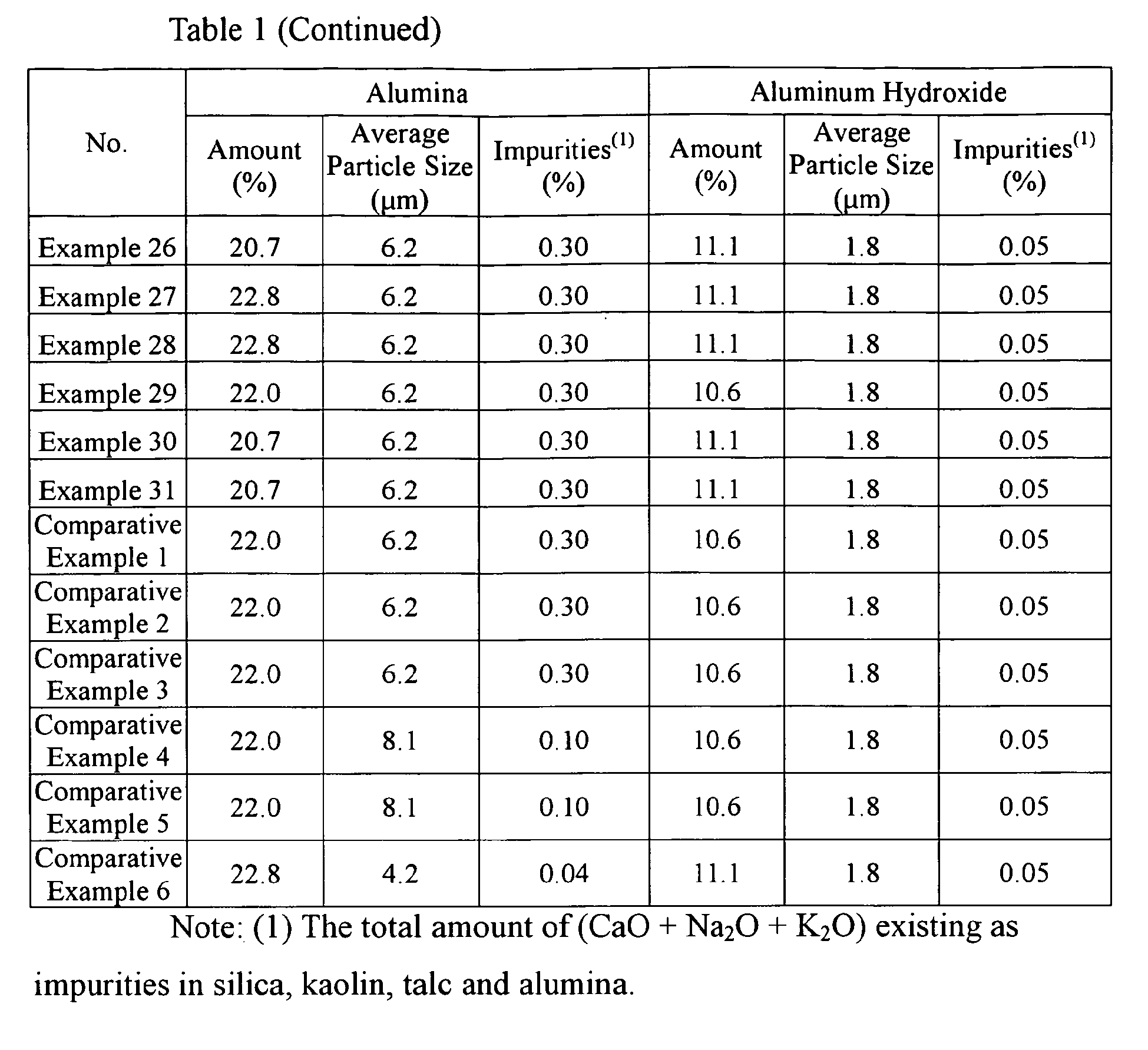


- It is clear from Table 2 that the ceramic honeycomb filters of Examples 1-31 within the present invention have smaller pressure loss while keeping enough strength in use. On the other hand, the ceramic honeycomb filters of Comparative Examples 1-6 have low air permeability and poor pressure loss or strength, failing to meet the requirements of pressure loss and strength.
- Because the ceramic honeycomb structure of the present invention keeps enough strength during use, with smaller pressure loss, it is suitable for large ceramic honeycomb filters of more than 200 mm in outer diameter.
Claims (14)
- A ceramic honeycomb structure having a large number of flow paths defined by porous cell walls having porosity of 45-68% and an average pore size of 15-35 µm, said ceramic honeycomb structure having pores meeting the following conditions:the volume of pores having diameters of more than 50 µm being more than 10% and 25% or less of the total pore volume;the volume of pores having diameters of 100 µm or more being 1-8% of the total pore volume;the volume of pores having diameters of less than 10 µm being 3-10% of the total pore volume; andsaid pores having a pore size distribution deviation σ [= log(D20) - log(D80)] of 0.45 or less, wherein D20 represents a pore size (µm) at a pore volume corresponding to 20% of the total pore volume, and D80 represents a pore size (µm) at a pore volume corresponding to 80% of the total pore volume, in a curve showing the relation between a pore size and a cumulative pore volume obtained by accumulating a pore volume from the maximum pore size to a particular pore size, and D80 < D20.
- The ceramic honeycomb structure according to claim 1, wherein said porous cell walls have air permeability of 4 x 10-12 m2 to 9 x 10-12 m2.
- The ceramic honeycomb structure according to claim 1 or 2, having an isostatic strength of 1 MPa or more.
- The ceramic honeycomb structure according to any one of claims 1-3, wherein said porous cell walls have a thickness of 0.2-0.3 mm and a cell density of 23-39 cells/cm2.
- The ceramic honeycomb structure according to any one of claims 1-4, which suffers pressure loss of 1.2 kPa or less, when capturing 2 g/liter of soot at a flow rate of 10 Nm3/min with a ceramic honeycomb filter obtained by alternately plugging flow path ends of a ceramic honeycomb structure of 266.7 mm in diameter and 304.8 mm in length having a cell density of 36.4 cells/cm2 and a cell wall thickness of 0.28 mm in a checkerboard pattern.
- The ceramic honeycomb structure according to any one of claims 1-5, wherein a main component of its crystal phase is cordierite, containing 3-6% of spinel and 1-8% of cristobalite.
- The ceramic honeycomb structure according to any one of claims 1-6, wherein said porosity is more than 58% and 66% or less.
- The ceramic honeycomb structure according to any one of claims 1-7, wherein said average pore size is 20-34 µm.
- The ceramic honeycomb structure according to any one of claims 1-8, which has a thermal expansion coefficient of 3 x 10⁻⁷ to 13 x 10-7 between 20°C and 800°C.
- A method for producing a ceramic honeycomb structure having a large number of flow paths defined by porous cell walls by extrusion-molding a moldable material comprising a cordierite-forming material and a pore-forming material, and sintering the resultant molding,
said cordierite-forming material containing 10-20% of silica;
said silica being in the form of powder having a mode diameter of 30-60 µm, particles having particle sizes of 20 µm or less being 2-10%, particles having particle sizes of 100 µm or more being 2-10%, and particles having particle sizes of 200 µm or more being 1% or less; and
said particles having a particle size distribution deviation SD [= log(d80) - log(d20)] of 0.5 or less, wherein d20 represents a particle size (µm) corresponding to a cumulative volume of 20%, and d80 represents a particle size (µm) corresponding to a cumulative volume of 80%, in a curve showing the relation between a particle size and a cumulative particle volume expressed by the volume percentage of particles having a particular particle size or less, and meeting d20 < d80. - The method for producing a ceramic honeycomb structure according to claim 10, wherein said pore-forming material is 1-15% based on said cordierite-forming material, and wherein said pore-forming material is in the form of powder having a mode diameter of 30-70 µm and a particle size distribution deviation SD of 0.5 or less.
- The method for producing a ceramic honeycomb structure according to claim 10 or 11, wherein the absolute value of the difference between the mode diameter M50 of said silica particles and the mode diameter m50 of said pore-forming material particles, |M50-m50|, is 15 µm or less.
- The method for producing a ceramic honeycomb structure according to any one of claims 10-12, wherein said silica particles have sphericity of 0.5 or more.
- The method for producing a ceramic honeycomb structure according to any one of claims 10-13, wherein said pore-forming material is more than 6% and 15% or less, based on said cordierite-forming material.
Applications Claiming Priority (2)
| Application Number | Priority Date | Filing Date | Title |
|---|---|---|---|
| JP2008193671 | 2008-07-28 | ||
| PCT/JP2009/055330 WO2010013509A1 (en) | 2008-07-28 | 2009-03-18 | Ceramic honeycomb structure and process for producing the same |
Publications (3)
| Publication Number | Publication Date |
|---|---|
| EP2335797A1 true EP2335797A1 (en) | 2011-06-22 |
| EP2335797A4 EP2335797A4 (en) | 2015-07-29 |
| EP2335797B1 EP2335797B1 (en) | 2019-03-06 |
Family
ID=41610219
Family Applications (1)
| Application Number | Title | Priority Date | Filing Date |
|---|---|---|---|
| EP09802754.3A Active EP2335797B1 (en) | 2008-07-28 | 2009-03-18 | Ceramic honeycomb structure |
Country Status (6)
| Country | Link |
|---|---|
| US (1) | US8691361B2 (en) |
| EP (1) | EP2335797B1 (en) |
| JP (1) | JP5464142B2 (en) |
| KR (1) | KR101648483B1 (en) |
| CN (1) | CN102089058B (en) |
| WO (1) | WO2010013509A1 (en) |
Cited By (11)
| Publication number | Priority date | Publication date | Assignee | Title |
|---|---|---|---|---|
| EP2784043A3 (en) * | 2013-03-29 | 2014-10-29 | NGK Insulators, Ltd. | Manufacturing method for honeycomb structure and honeycomb structure |
| EP2835167A1 (en) * | 2013-07-31 | 2015-02-11 | Ibiden Co., Ltd. | Honeycomb filter |
| WO2014189741A3 (en) * | 2013-05-20 | 2015-04-16 | Corning Incorporated | Porous ceramic article and method of manufacturing the same |
| EP2905058A4 (en) * | 2012-10-04 | 2016-04-06 | Ibiden Co Ltd | FILTER IN HONEYCOMB |
| US9376347B2 (en) | 2013-05-20 | 2016-06-28 | Corning Incorporated | Porous ceramic article and method of manufacturing the same |
| US9908260B2 (en) | 2013-05-20 | 2018-03-06 | Corning Incorporated | Porous ceramic article and method of manufacturing the same |
| EP3275852A4 (en) * | 2015-03-24 | 2018-11-21 | Hitachi Metals, Ltd. | Ceramic honeycomb structure and method for producing same |
| US10286358B2 (en) | 2013-07-31 | 2019-05-14 | Ibiden Co., Ltd. | Honeycomb filter |
| US11229902B2 (en) | 2016-05-31 | 2022-01-25 | Corning Incorporated | Porous article and method of manufacturing the same |
| EP3919153A4 (en) * | 2019-03-29 | 2022-03-30 | Denso Corporation | EXHAUST GAS PURIFICATION FILTER |
| US11447422B2 (en) | 2017-10-31 | 2022-09-20 | Corning Incorporated | Batch compositions comprising spheroidal pre-reacted inorganic particles and spheroidal pore-formers and methods of manufacture of honeycomb bodies therefrom |
Families Citing this family (29)
| Publication number | Priority date | Publication date | Assignee | Title |
|---|---|---|---|---|
| US8663777B2 (en) * | 2007-11-14 | 2014-03-04 | Hitachi Metals, Ltd. | Aluminum-titanate-based ceramic honeycomb structure, its production method, and starting material powder for producing same |
| WO2010114062A1 (en) * | 2009-03-31 | 2010-10-07 | 日立金属株式会社 | Ceramic honeycomb structure and process for producing same |
| JP5630437B2 (en) * | 2009-09-04 | 2014-11-26 | 日立金属株式会社 | Ceramic honeycomb structure |
| EP3120916B1 (en) * | 2010-02-22 | 2021-10-20 | Hitachi Metals, Ltd. | Production method for a ceramic honeycomb structure |
| US20130062275A1 (en) * | 2010-03-19 | 2013-03-14 | Sumitomo Chemical Company, Limited | Process for production of honeycomb structure, honeycomb structure, and particulate filter |
| WO2011125797A1 (en) * | 2010-04-01 | 2011-10-13 | 日立金属株式会社 | Ceramic honeycomb filter and method for producing same |
| US8999483B2 (en) | 2010-11-29 | 2015-04-07 | Corning Incorporated | Honeycomb structure comprising an outer cement skin and a cement therefor |
| US8450227B2 (en) * | 2011-02-28 | 2013-05-28 | Corning Incorporated | Ceramic-body-forming batch materials comprising silica, methods using the same and ceramic bodies made therefrom |
| JP5932230B2 (en) * | 2011-03-18 | 2016-06-08 | 日本碍子株式会社 | Honeycomb structure and manufacturing method thereof |
| BR112013025019A2 (en) * | 2011-03-31 | 2017-01-10 | Sumitomo Chemical Co | honeycomb structure |
| JP5829840B2 (en) * | 2011-06-17 | 2015-12-09 | 日本碍子株式会社 | Exhaust gas purification filter |
| WO2013054651A1 (en) * | 2011-10-11 | 2013-04-18 | 日立金属株式会社 | Method for producing ceramic honeycomb structure, and ceramic honeycomb structure |
| KR101351468B1 (en) * | 2012-04-09 | 2014-01-15 | (주) 세라컴 | Manufacturing method of diesel particulate filter and diesel particulate filter manufactured by the method |
| EP2915572A4 (en) * | 2012-11-01 | 2016-07-06 | Kyocera Corp | NETWORK STRUCTURE AND DEVICE FOR TREATING GAS USING THE SAME |
| US10370304B2 (en) * | 2012-11-29 | 2019-08-06 | Corning Incorporated | Fused silica based cellular structures |
| US9708958B2 (en) | 2013-09-24 | 2017-07-18 | Hitachi Metals, Ltd. | Cordierite-type ceramic honeycomb structure and its production method |
| CN105392759B (en) * | 2013-09-24 | 2018-01-26 | 日立金属株式会社 | Ceramic honeycomb structural body and its manufacture method |
| WO2016152727A1 (en) * | 2015-03-24 | 2016-09-29 | 日立金属株式会社 | Ceramic honeycomb structure |
| JP6594149B2 (en) * | 2015-10-05 | 2019-10-23 | 株式会社キャタラー | Exhaust gas purification device |
| US20180326613A1 (en) * | 2015-11-13 | 2018-11-15 | Asahi Kasei Kabushiki Kaisha | Methods for producing ceramic green body molded article and ceramic molded article |
| CN109414689A (en) * | 2016-07-14 | 2019-03-01 | 揖斐电株式会社 | The manufacturing method of honeycomb structure and the honeycomb structure |
| KR101993891B1 (en) * | 2018-12-28 | 2019-09-24 | (주)동영코프 | Method for manufacturing ceramic filter using silica and ceramic filter manufactured using the same |
| JP7274395B2 (en) * | 2019-10-11 | 2023-05-16 | 日本碍子株式会社 | honeycomb structure |
| JP7501540B2 (en) * | 2019-10-16 | 2024-06-18 | 株式会社プロテリアル | Ceramic honeycomb structure and manufacturing method thereof |
| JP7449721B2 (en) * | 2020-03-02 | 2024-03-14 | 日本碍子株式会社 | honeycomb filter |
| JP7353218B2 (en) * | 2020-03-02 | 2023-09-29 | 日本碍子株式会社 | honeycomb filter |
| KR102451008B1 (en) * | 2021-12-24 | 2022-10-06 | (주) 세라컴 | Diesel particle filter with improved internal defects and method for preparing the same |
| JP7709481B2 (en) * | 2023-03-30 | 2025-07-16 | 日本碍子株式会社 | Honeycomb structure and manufacturing method thereof |
| CN117028002A (en) * | 2023-05-25 | 2023-11-10 | 东莞市名创传动科技有限公司 | Filtering and muffling structure and preparation method thereof |
Family Cites Families (24)
| Publication number | Priority date | Publication date | Assignee | Title |
|---|---|---|---|---|
| JPS61129015A (en) | 1984-11-24 | 1986-06-17 | Nippon Denso Co Ltd | Filter for purifying exhaust gas and its preparation |
| US5141686A (en) | 1988-11-21 | 1992-08-25 | Corning Incorporated | Method for producing cordierite articles |
| JPH0738930B2 (en) | 1990-03-30 | 1995-05-01 | 日本碍子株式会社 | Manufacturing method of porous ceramic filter |
| JP3272746B2 (en) * | 1991-07-19 | 2002-04-08 | イビデン株式会社 | Diesel particulate filter |
| JPH10299454A (en) * | 1997-04-30 | 1998-11-10 | Matsushita Electric Ind Co Ltd | Exhaust gas filter, manufacturing method thereof, and sealing material for exhaust gas filter used therefor |
| KR20030036205A (en) * | 2000-06-01 | 2003-05-09 | 코닝 인코포레이티드 | Cordierite body |
| JP4094830B2 (en) | 2000-11-24 | 2008-06-04 | 日本碍子株式会社 | Porous honeycomb filter and manufacturing method thereof |
| JP4233031B2 (en) * | 2001-09-13 | 2009-03-04 | 日立金属株式会社 | Ceramic honeycomb filter and manufacturing method thereof |
| US6827754B2 (en) | 2001-09-13 | 2004-12-07 | Hitachi Metals, Ltd. | Ceramic honeycomb filter |
| EP1515787A4 (en) | 2002-06-26 | 2006-11-29 | Corning Inc | MAGNESIUM ALUMINUM SILICATE CONSTRUCTIONS FOR DPF APPLICATIONS |
| JP2004138308A (en) | 2002-10-17 | 2004-05-13 | Matsushita Electric Ind Co Ltd | Cooking equipment |
| JP2004250324A (en) * | 2003-01-30 | 2004-09-09 | Hitachi Metals Ltd | Method for producing ceramic honeycomb structure, and cordierite raw material |
| JP3935159B2 (en) | 2003-04-11 | 2007-06-20 | 日立金属株式会社 | Ceramic honeycomb filter |
| JP2004330118A (en) | 2003-05-09 | 2004-11-25 | Tokyo Yogyo Co Ltd | Exhaust gas purification filter |
| US7179316B2 (en) | 2003-06-25 | 2007-02-20 | Corning Incorporated | Cordierite filters with reduced pressure drop |
| JP2005052750A (en) * | 2003-08-05 | 2005-03-03 | Hitachi Metals Ltd | Ceramic honeycomb catalyst for exhaust gas cleaning apparatus and exhaust gas cleaning apparatus |
| DE112005000601T5 (en) | 2004-03-19 | 2007-03-01 | Ngk Insulators, Ltd. | Process for producing a porous ceramic structure |
| DE112005000638B4 (en) | 2004-03-24 | 2019-05-09 | Ngk Insulators, Ltd. | Process for producing a porous ceramic body |
| US7485170B2 (en) * | 2005-11-30 | 2009-02-03 | Corning Incorporated | Narrow pore size distribution cordierite ceramic honeycomb articles and methods for manufacturing same |
| WO2007102561A1 (en) * | 2006-03-07 | 2007-09-13 | Ngk Insulators, Ltd. | Ceramic structure and process for producing the same |
| JP4863904B2 (en) | 2006-03-31 | 2012-01-25 | イビデン株式会社 | Honeycomb structure and manufacturing method thereof |
| US8500840B2 (en) * | 2007-10-12 | 2013-08-06 | Hitachi Metals, Ltd. | Cordierite-based ceramic honeycomb filter and its production method |
| US8663777B2 (en) * | 2007-11-14 | 2014-03-04 | Hitachi Metals, Ltd. | Aluminum-titanate-based ceramic honeycomb structure, its production method, and starting material powder for producing same |
| US8187353B2 (en) * | 2009-01-21 | 2012-05-29 | Corning Incorporated | Filtration structures for improved particulate filter performance |
-
2009
- 2009-03-18 CN CN200980127387.4A patent/CN102089058B/en active Active
- 2009-03-18 US US13/056,086 patent/US8691361B2/en active Active
- 2009-03-18 KR KR1020117000548A patent/KR101648483B1/en active Active
- 2009-03-18 WO PCT/JP2009/055330 patent/WO2010013509A1/en not_active Ceased
- 2009-03-18 JP JP2010522640A patent/JP5464142B2/en active Active
- 2009-03-18 EP EP09802754.3A patent/EP2335797B1/en active Active
Non-Patent Citations (1)
| Title |
|---|
| See references of WO2010013509A1 * |
Cited By (16)
| Publication number | Priority date | Publication date | Assignee | Title |
|---|---|---|---|---|
| US9919255B2 (en) | 2012-10-04 | 2018-03-20 | Ibiden Co., Ltd. | Honeycomb filter |
| EP2905058A4 (en) * | 2012-10-04 | 2016-04-06 | Ibiden Co Ltd | FILTER IN HONEYCOMB |
| US9555355B2 (en) | 2013-03-29 | 2017-01-31 | Ngk Insulators, Ltd. | Manufacturing method for honeycomb structure and honeycomb structure |
| EP2784043A3 (en) * | 2013-03-29 | 2014-10-29 | NGK Insulators, Ltd. | Manufacturing method for honeycomb structure and honeycomb structure |
| US9908260B2 (en) | 2013-05-20 | 2018-03-06 | Corning Incorporated | Porous ceramic article and method of manufacturing the same |
| US9376347B2 (en) | 2013-05-20 | 2016-06-28 | Corning Incorporated | Porous ceramic article and method of manufacturing the same |
| US9623360B2 (en) | 2013-05-20 | 2017-04-18 | Corning Incorporated | Porous ceramic article and method of manufacturing the same |
| WO2014189741A3 (en) * | 2013-05-20 | 2015-04-16 | Corning Incorporated | Porous ceramic article and method of manufacturing the same |
| US9650928B2 (en) | 2013-07-31 | 2017-05-16 | Ibiden Co., Ltd. | Honeycomb filter |
| EP2835167A1 (en) * | 2013-07-31 | 2015-02-11 | Ibiden Co., Ltd. | Honeycomb filter |
| US10286358B2 (en) | 2013-07-31 | 2019-05-14 | Ibiden Co., Ltd. | Honeycomb filter |
| EP3275852A4 (en) * | 2015-03-24 | 2018-11-21 | Hitachi Metals, Ltd. | Ceramic honeycomb structure and method for producing same |
| US11229902B2 (en) | 2016-05-31 | 2022-01-25 | Corning Incorporated | Porous article and method of manufacturing the same |
| US11447422B2 (en) | 2017-10-31 | 2022-09-20 | Corning Incorporated | Batch compositions comprising spheroidal pre-reacted inorganic particles and spheroidal pore-formers and methods of manufacture of honeycomb bodies therefrom |
| US11591265B2 (en) | 2017-10-31 | 2023-02-28 | Corning Incorporated | Batch compositions comprising pre-reacted inorganic particles and methods of manufacture of green bodies therefrom |
| EP3919153A4 (en) * | 2019-03-29 | 2022-03-30 | Denso Corporation | EXHAUST GAS PURIFICATION FILTER |
Also Published As
| Publication number | Publication date |
|---|---|
| CN102089058B (en) | 2014-03-12 |
| US20110135873A1 (en) | 2011-06-09 |
| CN102089058A (en) | 2011-06-08 |
| US8691361B2 (en) | 2014-04-08 |
| JP5464142B2 (en) | 2014-04-09 |
| EP2335797A4 (en) | 2015-07-29 |
| JPWO2010013509A1 (en) | 2012-01-05 |
| KR101648483B1 (en) | 2016-08-16 |
| KR20110048506A (en) | 2011-05-11 |
| EP2335797B1 (en) | 2019-03-06 |
| WO2010013509A1 (en) | 2010-02-04 |
Similar Documents
| Publication | Publication Date | Title |
|---|---|---|
| EP2335797B1 (en) | Ceramic honeycomb structure | |
| EP3120916B1 (en) | Production method for a ceramic honeycomb structure | |
| US9726066B2 (en) | Cordierite-type ceramic honeycomb structure and its production method | |
| EP2455153B1 (en) | Method for manufacturing a ceramic honeycomb structure | |
| EP2228115B1 (en) | Cordierite ceramic honeycomb filter and process for producing the same | |
| EP2554237B1 (en) | Ceramic honeycomb filter and method for producing same | |
| US10065141B2 (en) | Ceramic honeycomb structure and its production method | |
| JPWO2007102561A1 (en) | Ceramic structure and manufacturing method thereof |
Legal Events
| Date | Code | Title | Description |
|---|---|---|---|
| PUAI | Public reference made under article 153(3) epc to a published international application that has entered the european phase |
Free format text: ORIGINAL CODE: 0009012 |
|
| 17P | Request for examination filed |
Effective date: 20110217 |
|
| AK | Designated contracting states |
Kind code of ref document: A1 Designated state(s): AT BE BG CH CY CZ DE DK EE ES FI FR GB GR HR HU IE IS IT LI LT LU LV MC MK MT NL NO PL PT RO SE SI SK TR |
|
| AX | Request for extension of the european patent |
Extension state: AL BA RS |
|
| DAX | Request for extension of the european patent (deleted) | ||
| RA4 | Supplementary search report drawn up and despatched (corrected) |
Effective date: 20150629 |
|
| RIC1 | Information provided on ipc code assigned before grant |
Ipc: B01D 39/20 20060101AFI20150623BHEP Ipc: F01N 3/02 20060101ALI20150623BHEP Ipc: C04B 38/00 20060101ALI20150623BHEP Ipc: B01D 46/24 20060101ALN20150623BHEP |
|
| STAA | Information on the status of an ep patent application or granted ep patent |
Free format text: STATUS: EXAMINATION IS IN PROGRESS |
|
| 17Q | First examination report despatched |
Effective date: 20171117 |
|
| GRAP | Despatch of communication of intention to grant a patent |
Free format text: ORIGINAL CODE: EPIDOSNIGR1 |
|
| STAA | Information on the status of an ep patent application or granted ep patent |
Free format text: STATUS: GRANT OF PATENT IS INTENDED |
|
| RIC1 | Information provided on ipc code assigned before grant |
Ipc: F01N 3/02 20060101ALI20180928BHEP Ipc: B01D 39/20 20060101AFI20180928BHEP Ipc: C04B 38/00 20060101ALI20180928BHEP Ipc: B01D 46/24 20060101ALI20180928BHEP |
|
| INTG | Intention to grant announced |
Effective date: 20181025 |
|
| RIN1 | Information on inventor provided before grant (corrected) |
Inventor name: ISHIZAWA, TOSHITAKA Inventor name: OKAZAKI, SHUNJI |
|
| GRAS | Grant fee paid |
Free format text: ORIGINAL CODE: EPIDOSNIGR3 |
|
| GRAA | (expected) grant |
Free format text: ORIGINAL CODE: 0009210 |
|
| STAA | Information on the status of an ep patent application or granted ep patent |
Free format text: STATUS: THE PATENT HAS BEEN GRANTED |
|
| AK | Designated contracting states |
Kind code of ref document: B1 Designated state(s): AT BE BG CH CY CZ DE DK EE ES FI FR GB GR HR HU IE IS IT LI LT LU LV MC MK MT NL NO PL PT RO SE SI SK TR |
|
| REG | Reference to a national code |
Ref country code: GB Ref legal event code: FG4D |
|
| REG | Reference to a national code |
Ref country code: CH Ref legal event code: EP Ref country code: AT Ref legal event code: REF Ref document number: 1103787 Country of ref document: AT Kind code of ref document: T Effective date: 20190315 |
|
| REG | Reference to a national code |
Ref country code: DE Ref legal event code: R096 Ref document number: 602009057349 Country of ref document: DE |
|
| REG | Reference to a national code |
Ref country code: IE Ref legal event code: FG4D |
|
| REG | Reference to a national code |
Ref country code: NL Ref legal event code: MP Effective date: 20190306 |
|
| REG | Reference to a national code |
Ref country code: LT Ref legal event code: MG4D |
|
| PG25 | Lapsed in a contracting state [announced via postgrant information from national office to epo] |
Ref country code: NO Free format text: LAPSE BECAUSE OF FAILURE TO SUBMIT A TRANSLATION OF THE DESCRIPTION OR TO PAY THE FEE WITHIN THE PRESCRIBED TIME-LIMIT Effective date: 20190606 Ref country code: LT Free format text: LAPSE BECAUSE OF FAILURE TO SUBMIT A TRANSLATION OF THE DESCRIPTION OR TO PAY THE FEE WITHIN THE PRESCRIBED TIME-LIMIT Effective date: 20190306 Ref country code: SE Free format text: LAPSE BECAUSE OF FAILURE TO SUBMIT A TRANSLATION OF THE DESCRIPTION OR TO PAY THE FEE WITHIN THE PRESCRIBED TIME-LIMIT Effective date: 20190306 Ref country code: FI Free format text: LAPSE BECAUSE OF FAILURE TO SUBMIT A TRANSLATION OF THE DESCRIPTION OR TO PAY THE FEE WITHIN THE PRESCRIBED TIME-LIMIT Effective date: 20190306 |
|
| PG25 | Lapsed in a contracting state [announced via postgrant information from national office to epo] |
Ref country code: HR Free format text: LAPSE BECAUSE OF FAILURE TO SUBMIT A TRANSLATION OF THE DESCRIPTION OR TO PAY THE FEE WITHIN THE PRESCRIBED TIME-LIMIT Effective date: 20190306 Ref country code: LV Free format text: LAPSE BECAUSE OF FAILURE TO SUBMIT A TRANSLATION OF THE DESCRIPTION OR TO PAY THE FEE WITHIN THE PRESCRIBED TIME-LIMIT Effective date: 20190306 Ref country code: NL Free format text: LAPSE BECAUSE OF FAILURE TO SUBMIT A TRANSLATION OF THE DESCRIPTION OR TO PAY THE FEE WITHIN THE PRESCRIBED TIME-LIMIT Effective date: 20190306 Ref country code: BG Free format text: LAPSE BECAUSE OF FAILURE TO SUBMIT A TRANSLATION OF THE DESCRIPTION OR TO PAY THE FEE WITHIN THE PRESCRIBED TIME-LIMIT Effective date: 20190606 Ref country code: GR Free format text: LAPSE BECAUSE OF FAILURE TO SUBMIT A TRANSLATION OF THE DESCRIPTION OR TO PAY THE FEE WITHIN THE PRESCRIBED TIME-LIMIT Effective date: 20190607 |
|
| REG | Reference to a national code |
Ref country code: AT Ref legal event code: MK05 Ref document number: 1103787 Country of ref document: AT Kind code of ref document: T Effective date: 20190306 |
|
| PG25 | Lapsed in a contracting state [announced via postgrant information from national office to epo] |
Ref country code: EE Free format text: LAPSE BECAUSE OF FAILURE TO SUBMIT A TRANSLATION OF THE DESCRIPTION OR TO PAY THE FEE WITHIN THE PRESCRIBED TIME-LIMIT Effective date: 20190306 Ref country code: PT Free format text: LAPSE BECAUSE OF FAILURE TO SUBMIT A TRANSLATION OF THE DESCRIPTION OR TO PAY THE FEE WITHIN THE PRESCRIBED TIME-LIMIT Effective date: 20190706 Ref country code: SK Free format text: LAPSE BECAUSE OF FAILURE TO SUBMIT A TRANSLATION OF THE DESCRIPTION OR TO PAY THE FEE WITHIN THE PRESCRIBED TIME-LIMIT Effective date: 20190306 Ref country code: ES Free format text: LAPSE BECAUSE OF FAILURE TO SUBMIT A TRANSLATION OF THE DESCRIPTION OR TO PAY THE FEE WITHIN THE PRESCRIBED TIME-LIMIT Effective date: 20190306 Ref country code: IT Free format text: LAPSE BECAUSE OF FAILURE TO SUBMIT A TRANSLATION OF THE DESCRIPTION OR TO PAY THE FEE WITHIN THE PRESCRIBED TIME-LIMIT Effective date: 20190306 Ref country code: CZ Free format text: LAPSE BECAUSE OF FAILURE TO SUBMIT A TRANSLATION OF THE DESCRIPTION OR TO PAY THE FEE WITHIN THE PRESCRIBED TIME-LIMIT Effective date: 20190306 Ref country code: RO Free format text: LAPSE BECAUSE OF FAILURE TO SUBMIT A TRANSLATION OF THE DESCRIPTION OR TO PAY THE FEE WITHIN THE PRESCRIBED TIME-LIMIT Effective date: 20190306 |
|
| REG | Reference to a national code |
Ref country code: CH Ref legal event code: PL |
|
| PG25 | Lapsed in a contracting state [announced via postgrant information from national office to epo] |
Ref country code: LU Free format text: LAPSE BECAUSE OF NON-PAYMENT OF DUE FEES Effective date: 20190318 Ref country code: PL Free format text: LAPSE BECAUSE OF FAILURE TO SUBMIT A TRANSLATION OF THE DESCRIPTION OR TO PAY THE FEE WITHIN THE PRESCRIBED TIME-LIMIT Effective date: 20190306 |
|
| REG | Reference to a national code |
Ref country code: DE Ref legal event code: R097 Ref document number: 602009057349 Country of ref document: DE |
|
| REG | Reference to a national code |
Ref country code: BE Ref legal event code: MM Effective date: 20190331 |
|
| PG25 | Lapsed in a contracting state [announced via postgrant information from national office to epo] |
Ref country code: AT Free format text: LAPSE BECAUSE OF FAILURE TO SUBMIT A TRANSLATION OF THE DESCRIPTION OR TO PAY THE FEE WITHIN THE PRESCRIBED TIME-LIMIT Effective date: 20190306 Ref country code: IS Free format text: LAPSE BECAUSE OF FAILURE TO SUBMIT A TRANSLATION OF THE DESCRIPTION OR TO PAY THE FEE WITHIN THE PRESCRIBED TIME-LIMIT Effective date: 20190706 |
|
| PLBE | No opposition filed within time limit |
Free format text: ORIGINAL CODE: 0009261 |
|
| STAA | Information on the status of an ep patent application or granted ep patent |
Free format text: STATUS: NO OPPOSITION FILED WITHIN TIME LIMIT |
|
| PG25 | Lapsed in a contracting state [announced via postgrant information from national office to epo] |
Ref country code: LI Free format text: LAPSE BECAUSE OF NON-PAYMENT OF DUE FEES Effective date: 20190331 Ref country code: DK Free format text: LAPSE BECAUSE OF FAILURE TO SUBMIT A TRANSLATION OF THE DESCRIPTION OR TO PAY THE FEE WITHIN THE PRESCRIBED TIME-LIMIT Effective date: 20190306 Ref country code: IE Free format text: LAPSE BECAUSE OF NON-PAYMENT OF DUE FEES Effective date: 20190318 Ref country code: CH Free format text: LAPSE BECAUSE OF NON-PAYMENT OF DUE FEES Effective date: 20190331 Ref country code: MC Free format text: LAPSE BECAUSE OF FAILURE TO SUBMIT A TRANSLATION OF THE DESCRIPTION OR TO PAY THE FEE WITHIN THE PRESCRIBED TIME-LIMIT Effective date: 20190306 |
|
| 26N | No opposition filed |
Effective date: 20191209 |
|
| GBPC | Gb: european patent ceased through non-payment of renewal fee |
Effective date: 20190606 |
|
| PG25 | Lapsed in a contracting state [announced via postgrant information from national office to epo] |
Ref country code: SI Free format text: LAPSE BECAUSE OF FAILURE TO SUBMIT A TRANSLATION OF THE DESCRIPTION OR TO PAY THE FEE WITHIN THE PRESCRIBED TIME-LIMIT Effective date: 20190306 Ref country code: BE Free format text: LAPSE BECAUSE OF NON-PAYMENT OF DUE FEES Effective date: 20190331 |
|
| PG25 | Lapsed in a contracting state [announced via postgrant information from national office to epo] |
Ref country code: TR Free format text: LAPSE BECAUSE OF FAILURE TO SUBMIT A TRANSLATION OF THE DESCRIPTION OR TO PAY THE FEE WITHIN THE PRESCRIBED TIME-LIMIT Effective date: 20190306 |
|
| PG25 | Lapsed in a contracting state [announced via postgrant information from national office to epo] |
Ref country code: GB Free format text: LAPSE BECAUSE OF NON-PAYMENT OF DUE FEES Effective date: 20190606 |
|
| PG25 | Lapsed in a contracting state [announced via postgrant information from national office to epo] |
Ref country code: MT Free format text: LAPSE BECAUSE OF NON-PAYMENT OF DUE FEES Effective date: 20190318 |
|
| PG25 | Lapsed in a contracting state [announced via postgrant information from national office to epo] |
Ref country code: CY Free format text: LAPSE BECAUSE OF FAILURE TO SUBMIT A TRANSLATION OF THE DESCRIPTION OR TO PAY THE FEE WITHIN THE PRESCRIBED TIME-LIMIT Effective date: 20190306 |
|
| PG25 | Lapsed in a contracting state [announced via postgrant information from national office to epo] |
Ref country code: HU Free format text: LAPSE BECAUSE OF FAILURE TO SUBMIT A TRANSLATION OF THE DESCRIPTION OR TO PAY THE FEE WITHIN THE PRESCRIBED TIME-LIMIT; INVALID AB INITIO Effective date: 20090318 |
|
| PG25 | Lapsed in a contracting state [announced via postgrant information from national office to epo] |
Ref country code: MK Free format text: LAPSE BECAUSE OF FAILURE TO SUBMIT A TRANSLATION OF THE DESCRIPTION OR TO PAY THE FEE WITHIN THE PRESCRIBED TIME-LIMIT Effective date: 20190306 |
|
| REG | Reference to a national code |
Ref country code: DE Ref legal event code: R081 Ref document number: 602009057349 Country of ref document: DE Owner name: PROTERIAL, LTD., JP Free format text: FORMER OWNER: HITACHI METALS, LTD., TOKIO/TOKYO, JP Ref country code: DE Ref legal event code: R081 Ref document number: 602009057349 Country of ref document: DE Owner name: MIRAI CASTING AMERICA, INC., FARMINGTON HILLS, US Free format text: FORMER OWNER: HITACHI METALS, LTD., TOKIO/TOKYO, JP |
|
| PGFP | Annual fee paid to national office [announced via postgrant information from national office to epo] |
Ref country code: DE Payment date: 20260128 Year of fee payment: 18 |
|
| PGFP | Annual fee paid to national office [announced via postgrant information from national office to epo] |
Ref country code: FR Payment date: 20260209 Year of fee payment: 18 |
|
| REG | Reference to a national code |
Ref country code: DE Ref legal event code: R081 Ref document number: 602009057349 Country of ref document: DE Owner name: MIRAI CASTING AMERICA, INC., FARMINGTON HILLS, US Free format text: FORMER OWNER: PROTERIAL, LTD., TOKYO, JP |
|
| REG | Reference to a national code |
Ref country code: DE Ref legal event code: R081 Ref document number: 602009057349 Country of ref document: DE Owner name: MIRAI CASTING AMERICA, INC., FARMINGTON HILLS, US Free format text: FORMER OWNER: MIRAI CASTING HOLDINGS, LTD., TOKYO, JP |