EP2335773A1 - Membrane empilée pour soupape actionnée par la pression - Google Patents
Membrane empilée pour soupape actionnée par la pression Download PDFInfo
- Publication number
- EP2335773A1 EP2335773A1 EP11158827A EP11158827A EP2335773A1 EP 2335773 A1 EP2335773 A1 EP 2335773A1 EP 11158827 A EP11158827 A EP 11158827A EP 11158827 A EP11158827 A EP 11158827A EP 2335773 A1 EP2335773 A1 EP 2335773A1
- Authority
- EP
- European Patent Office
- Prior art keywords
- membrane
- flow control
- thickness
- flow
- pressure
- Prior art date
- Legal status (The legal status is an assumption and is not a legal conclusion. Google has not performed a legal analysis and makes no representation as to the accuracy of the status listed.)
- Withdrawn
Links
Images


Classifications
-
- F—MECHANICAL ENGINEERING; LIGHTING; HEATING; WEAPONS; BLASTING
- F16—ENGINEERING ELEMENTS AND UNITS; GENERAL MEASURES FOR PRODUCING AND MAINTAINING EFFECTIVE FUNCTIONING OF MACHINES OR INSTALLATIONS; THERMAL INSULATION IN GENERAL
- F16K—VALVES; TAPS; COCKS; ACTUATING-FLOATS; DEVICES FOR VENTING OR AERATING
- F16K15/00—Check valves
- F16K15/14—Check valves with flexible valve members
- F16K15/144—Check valves with flexible valve members the closure elements being fixed along all or a part of their periphery
- F16K15/147—Check valves with flexible valve members the closure elements being fixed along all or a part of their periphery the closure elements having specially formed slits or being of an elongated easily collapsible form
-
- A—HUMAN NECESSITIES
- A61—MEDICAL OR VETERINARY SCIENCE; HYGIENE
- A61M—DEVICES FOR INTRODUCING MEDIA INTO, OR ONTO, THE BODY; DEVICES FOR TRANSDUCING BODY MEDIA OR FOR TAKING MEDIA FROM THE BODY; DEVICES FOR PRODUCING OR ENDING SLEEP OR STUPOR
- A61M39/00—Tubes, tube connectors, tube couplings, valves, access sites or the like, specially adapted for medical use
- A61M39/02—Access sites
-
- A—HUMAN NECESSITIES
- A61—MEDICAL OR VETERINARY SCIENCE; HYGIENE
- A61M—DEVICES FOR INTRODUCING MEDIA INTO, OR ONTO, THE BODY; DEVICES FOR TRANSDUCING BODY MEDIA OR FOR TAKING MEDIA FROM THE BODY; DEVICES FOR PRODUCING OR ENDING SLEEP OR STUPOR
- A61M39/00—Tubes, tube connectors, tube couplings, valves, access sites or the like, specially adapted for medical use
- A61M39/22—Valves or arrangement of valves
- A61M39/24—Check- or non-return valves
-
- F—MECHANICAL ENGINEERING; LIGHTING; HEATING; WEAPONS; BLASTING
- F16—ENGINEERING ELEMENTS AND UNITS; GENERAL MEASURES FOR PRODUCING AND MAINTAINING EFFECTIVE FUNCTIONING OF MACHINES OR INSTALLATIONS; THERMAL INSULATION IN GENERAL
- F16K—VALVES; TAPS; COCKS; ACTUATING-FLOATS; DEVICES FOR VENTING OR AERATING
- F16K17/00—Safety valves; Equalising valves, e.g. pressure relief valves
- F16K17/18—Safety valves; Equalising valves, e.g. pressure relief valves opening on surplus pressure on either side
-
- A—HUMAN NECESSITIES
- A61—MEDICAL OR VETERINARY SCIENCE; HYGIENE
- A61M—DEVICES FOR INTRODUCING MEDIA INTO, OR ONTO, THE BODY; DEVICES FOR TRANSDUCING BODY MEDIA OR FOR TAKING MEDIA FROM THE BODY; DEVICES FOR PRODUCING OR ENDING SLEEP OR STUPOR
- A61M39/00—Tubes, tube connectors, tube couplings, valves, access sites or the like, specially adapted for medical use
- A61M39/22—Valves or arrangement of valves
- A61M39/24—Check- or non-return valves
- A61M2039/242—Check- or non-return valves designed to open when a predetermined pressure or flow rate has been reached, e.g. check valve actuated by fluid
-
- A—HUMAN NECESSITIES
- A61—MEDICAL OR VETERINARY SCIENCE; HYGIENE
- A61M—DEVICES FOR INTRODUCING MEDIA INTO, OR ONTO, THE BODY; DEVICES FOR TRANSDUCING BODY MEDIA OR FOR TAKING MEDIA FROM THE BODY; DEVICES FOR PRODUCING OR ENDING SLEEP OR STUPOR
- A61M39/00—Tubes, tube connectors, tube couplings, valves, access sites or the like, specially adapted for medical use
- A61M39/22—Valves or arrangement of valves
- A61M39/24—Check- or non-return valves
- A61M2039/2426—Slit valve
Definitions
- blood may be removed from the body for external filtering and purification, to make up for the inability of the patient's kidneys to carry out that function.
- the patient's venous blood is extracted, processed in a dialysis machine and returned to the patient.
- the dialysis machine purifies the blood by diffusing harmful compounds through membranes, and may add to the blood therapeutic agents, nutrients etc., as required before returning it to the patient's body.
- the blood is extracted from a source vein (e.g., the vena cava) through a catheter sutured to the skin with a distal needle of the catheter penetrating the source vein.
- the needle and catheter are generally implanted semi permanently with a distal portion of the assembly remaining within the patient in contact with the vascular system while a proximal portion of the catheter remains external to the patient's body.
- the proximal end is sealed after each dialysis session has been completed to prevent blood loss and infections.
- even small amounts of blood oozing into the proximal end of the catheter may be dangerous as thrombi can form therein due to coagulation. These thrombi may then be introduced into the patient's vascular system when blood flows from the dialysis machine through the catheter in a later session.
- a common method of sealing the catheter after a dialysis session is to shut the catheter with a simple clamp. This method is often unsatisfactory because the repeated application of the clamp may weaken the walls of the catheter due to the stress placed on the walls at a single point. In addition, the pinched area of the catheter may not be completely sealed allowing air to enter the catheter which may coagulate any blood present within the catheter.
- valves have been used at the opening of the catheter in an attempt to prevent leaking through the catheter when the dialysis machine is disconnected. However, the unreliability of conventional valves has rendered them unsatisfactory for extended use.
- PASV Pressure Activated Safety Valve
- the present invention is directed to a pressure activated valve for medical applications comprising a housing having a lumen extending therethrough from a proximal end to a distal end thereof and a flow control membrane extending across the lumen to control flow therethrough, the flow control membrane including a mounting portion at which the flow control membrane is coupled to the housing and a lumen occluding portion having a slit extending therethrough so that, when the lumen occluding portion is subjected to a pressure of at least a predetermined threshold level, the lumen occluding portion moves from a closed configuration in which flow through the lumen is prevented to an open configuration in which flow is permitted and wherein a thickness of the mounting portion is greater than a thickness of the lumen occluding portion.
- the present invention is further directed to a method of forming a membrane for a pressure activated valve, comprising the steps of forming a substantially planar flow control membrane dimensioned to fit in a housing of the pressure activated valve, wherein a mounting portion of the flow control membrane is adapted to engage the housing and forming at least one slit in the flow control membrane, the slit being openable by pressure of a fluid in the pressure activated valve of at least a predetermined threshold level in combination with the steps of forming an annular base membrane dimensioned to substantially overlie the mounting portion of the flow control membrane and stacking the base membrane on the mounting portion of the flow control membrane.
- the present invention may be further understood with reference to the following description and the appended drawings, wherein like elements are referred to with the same reference numerals.
- the invention is related to the field of medical valves, and more specifically to the field of pressure activated valves that are used to seal a lumen of a medical catheter.
- Semi-permanently placed catheters may be useful for a variety of medical procedures which require repeated access to a patient's vascular system in addition to the dialysis treatments mentioned above. For example, chemotherapy infusions may be repeated several times a week for extended periods of time. For safety reasons, as well as to improve the comfort of the patient, injections of these therapeutic agents may be better carried out with an implantable, semi-permanent vascular access catheter. Many other conditions that require chronic venous supply of therapeutic agents, nutrients, blood products or other fluids to the patient may also benefit from implantable access catheters, to avoid repeated insertion of a needle into the patient's blood vessels. Thus, although the following description focuses on dialysis, those skilled in the art will understand that the invention may be used in conjunction with any of a wide variety of procedures which require long term implantation of catheters within the body.
- implantable catheters examples include those manufactured by VaxcelTM, such as the Chronic Dialysis Catheter and the Implantable Vascular Access System. These devices typically are inserted under the patient's skin, and have a distal end which includes a needle used to enter a blood vessel. The devices also have a proximal end extending outside the body for connection with an outside line. These semi-permanent catheters may be sutured to the patient's skin to maintain them in place while the patient goes about his or her normal occupations. These catheters may include two or more lumens which are used respectively to remove fluids from and to reintroduce to the blood vessel. When the catheter is disconnected from the dialysis machine, it can be left within the patient, connected to the patient's vascular system.
- a conventional clamp or a clip can be used to seal the catheter between medical sessions, but several drawbacks exist with this method.
- the material of the catheter wall can be damaged by the clamp, since the sealing force is exerted on a very small surface area of the catheter. Repeatedly clamping and releasing the catheter may, over time, weaken the material sufficiently to cause a failure of the catheter. This is dangerous for the patient, since it can lead to loss of blood and to infection.
- a sealing clamp may also become dislodged during activities of the patient, thus increasing the risk of leaks, infections, and various other problems listed above. Placing a clamp on the catheter's proximal end may also increase the bulk of the device which is exposed outside the patient's body, and may adversely affect patient comfort.
- An alternative to clamping the catheter's proximal end is to include self sealing valves near the entrance of the flow passages of the catheter, to seal those passages when not used.
- one or more valves may be placed in the catheter (e.g., near a proximal end thereof).
- the valves are preferably designed to seal the catheter's lumen under certain conditions, and to allow passage of a fluid under other conditions.
- the system of valves may seal the catheter when it is not connected to an operating dialysis machine, and may allow both an outflow of non-purified blood and an inflow of purified blood to the patient when an operating dialysis machine is connected thereto.
- the valves used in dialysis thus selectively allow bidirectional flow into the patient and out of the patient, depending on the pressures applied thereto.
- Pressure activated safety valves are one type of flow control device that is often used to seal such semi-permanently implanted vascular catheters when not in use. These valves function by opening when subject to a pre-determined flow pressure, and by remaining closed when subject to pressures less than the predetermined flow pressure.
- the valve may be set to open when subject to a pressure which would be applied thereto by an operating dialysis machine and to remain closed when subject to lesser pressures (e.g., pressures applied by the vascular system itself).
- the pressure in the lumen is insufficient to open the PASV, and the dialysis catheter remains sealed.
- the PASV may be calibrated such that the pressure due to the blood flowing naturally through the patient's vascular system is not sufficient to open it and unseal the catheter.
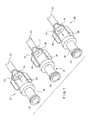
- Figures 1A- 1C show cutaway views of a PASV 20 (a three-way safety valve), depicting three flow conditions.
- condition A a fluid is introduced into the catheter 22 via a hub 18.
- condition C fluid is removed from the catheter 22 through the hub 18, and in condition B the valve is closed and no fluid flows therethrough.
- condition A is infusion, i.e ., blood is traveling from the dialysis machine to the patient and condition C is aspiration, i.e ., blood is traveling from the patient to the dialysis machine.
- Condition B corresponds to a closed state where the valve membrane is in the closed position allowing no fluid travel, e.g ., a condition in which no dialysis treatment is ongoing so that the valve 20 remains in the closed configuration.
- the closed position prevents bleedback.
- the valve 20 comprises a valve housing 30 forming a body of the device and a flow control membrane 32 disposed within the housing 30.
- the hub 18 may define the valve housing 30 or, alternatively, the housing 30 and the hub 18 may be formed as separate units.
- a fluid flow chamber 36 extends through the housing 30 so that fluid (e.g., blood) may flow therethrough into and out of the catheter 22.
- the exemplary flow chamber 36 is shown as substantially cylindrical, in different applications the flow chamber 36 may be of any other shape suitable for the efficient flow of a fluid.
- the housing 30 may be connected to a medical device (for example a dialysis machine) on a proximal side and to a patient line (for example a dialysis catheter) on the distal side.
- a medical device for example a dialysis machine
- a patient line for example a dialysis catheter
- a flow control membrane 32 may be disposed in the flow chamber 36 positioned to selectively impede the passage of fluid though flow chamber 36.
- the flow control membrane may, for example, be located adjacent the proximal end of the housing 30.
- One or more slits 34 are extend through the membrane 32 so that under predetermined conditions, the slit 34 opens. When the membrane 32 is not subject to the predetermined conditions, the slit 34 remains closed.
- the flow control membrane 32 may be constructed so that the slit 34 opens when subject to a flow pressure of at least a predetermined threshold level, but remains securely closed when a flow pressure impinging thereon is less than this threshold level.
- This threshold valve opening pressure may correspond, for example, to pressures to which the valve would be subjected if an operating dialysis machine were connected thereto and will preferably be substantially greater than pressure to which the membrane 32 would be generated by the patient's vascular system or which would be induced in the housing 30 due to patient activity.
- the valve 20 is therefore expressly designed so that the pressure imparted thereto through the operation of a dialysis machine will open the slit 34 and allow a desired volumetric flow of blood to pass through between the proximal and distal ends of the housing to and from the dialysis machine and the patient's vascular system.
- membrane 32 is formed so that, when not subject to a pressure of at least the threshold level, edges of the slit 34 remain joined.
- a first exemplary embodiment may be a 0.010 inch membrane sandwiched between two membranes having a thickness of 0.0025 inches.
- a second exemplary embodiment may be two 0.010 inch membranes stacked together.
- An exemplary durometer hardness may be 55A and an exemplary slit length of 9 mm.
- valve performance may be varied by altering the choice of materials for the membrane 32 (e.g ., varying durometer and compression), a thickness of the materials and a size of the slit 34.
- additional stiffening members may be used for that purpose.
- the flow control membrane 32 is securely held in place within the housing 30, so that it will not be displaced by the force of the fluid flowing through the valve 20.
- the flow control membrane 32 may be placed on a membrane seat 50 of the housing 30.
- the membrane 32 may, for example, be sandwiched between separable portions of the housing 30, so that a membrane retention portion 52 of the housing 30 applies a compressive force to a periphery of flow control membrane 32 thereby maintaining it in a desired position within the housing.
- the membrane 32 may be deformed possibly resulting in puckering or other deformation thereof. This may prevent the slit 34 from closing completely resulting in an insufficient seal and the many disadvantages associated therewith.
- Too strong a compressive force applied to the membrane 32 may also cause stress cracks to form thereon at locations where the force is applied. Specifically, cracks may appear near a seating portion of the membrane 32 at which it is compressed between the membrane seat 50 and the membrane retention portion 52 of the housing 30.
- the seating portion is an annular region comprising a periphery of the flow control membrane 32.
- the housing may be formed by two halves, which are joined together to sandwich the flow control membrane 32 therebetween.
- propagation of the slit may result as strain concentrates at ends thereof when a fluid flows through the valve 20, forcing the slit 34 to the open configuration. If the membrane 32 is too thin, edges of the membrane 32 that are retained by the housing may not completely immobilize the membrane 32. Ths additional movement of the thin membrane 32 may cause further strains to be exerted on edges of the slit(s) 34, resulting in propagation of the slit and possible failure of the valve 20. This may cause the slit 34 to grow to a size whereby the resilience of the material of the membrane 32 is no longer able to maintain the edges of the slit 34 in contact with one another when subject to pressures below the threshold level.
- the flow control membrane 32 is formed as thickly as possible to prevent deformation of the surface of the membrane 32 and to prevent cracks from propagating near the periphery of the membrane 32 and at the edges of the slit 34.
- the design of the flow control membrane 32 takes into consideration parameters in addition to structural strength. For example, a large flow rate through the valve 20 is desirable to minimize the time necessary to carry out procedures such as dialysis.
- the flow rate through a PASV valve is affected by the thickness of the flow control membrane 32, among other things. The thinner the membrane is made, the higher the rate of flow through the valve 20 as the slit 34 will open more widely for a given pressure applied thereto.
- a compromise is generally made by selecting a thickness of the membrane 32 which provides an acceptable structural reliability of the membrane 32 and at the same time allows sufficient flow of fluid therethrough. It is desired to enhance the structural integrity of the valve 20 while maintaining or increasing a flow rate therethrough for a given flow pressure.
- a stacked membrane which satisfies in an optimal manner the two competing design goals of long structural life and high fluid flow rate.
- This result is achieved by using a thin flow control membrane 102 having one or more slits 106 extending therethrough to selectively impede the flow of a fluid through the valve 20.
- the flow control membrane 102 is made as thin as necessary to achieve a desired flow rate therethrough at the expected pressure (e.g., the pressure applied by an operating dialysis machine).
- a base membrane 104 is stacked thereon.
- the base membrane 104 is formed as desired to provide the extra strength necessary at the periphery of the thin membrane 102 to withstand the compressive forces exerted thereon.
- This base membrane 104 may preferably be made as thick as or thicker than the thin membrane 102.
- the base membrane 104 is preferably formed with a large opening formed in a center thereof so that a large portion of the thin membrane 102 is exposed while the seating portion to which the compressive forces are to be applied by the housing 30 is reinforced by the base membrane 104.
- the stacking order fo the membranes 102, 104 may be changed, without affecting the properties of the resulting stacked membrane.
- the thin membrane 102 may be sandwiched between a pair of base membranes 104 for extra support.
- the resulting stacked membrane will have a greater thickness at locations where the retaining compressive force are exerted by the valve housing 30 while the portion of the stacked membrane surrounding the slits 106 is thinner to allow for a greater flow rate.
- Exemplary ranges for the thickness b1 and b2 as shown in Figure 2 may be 0.005 - 0.1 inches.
- the base membrane 104 may be tapered to direct the flow of fluid into the valve.
- Figure 2 shows a perspective view of a stacked membrane 100 of a PASV according to an embodiment of the present invention.
- the stacked membrane 100 comprises a flow control membrane 102 and a base membrane 104.
- the flow control membrane 102 is designed to extend across the flow chamber 36 of a valve housing 30, as shown in Fig. 1 , in such a way that, when closed, it prevents the flow of fluids through the flow chamber 36.
- a surface 110 of the flow control membrane 102 may have dimensions substantially equal to the cross sectional area of housing 30.
- Two curved slits 106 are formed in the exemplary flow control membrane 102, to selectively allow the passage of fluid therethrough.
- Opposing slit edges 112, 114 are joined when the stacked membrane 100 are maintained in the closed configuration through the natural bias of the material, so that no fluid passes therethrough.
- the resilient material forming the flow control membrane 102 applies a restoring force which urges edges 112, 114 to join.
- external resilient elements may be added to the membrane 102 in proximity to the slits 106, to urge the edges to join.
- the edges 112, 114 are pushed apart against the restoring resilient force applied thereto, and the slits 106 open.
- the valve assumes the open configuration and flow is allowed to pass across flow control membrane 102.
- different shapes, sizes, and configurations of one or more slits 106 may be used to allow fluid to flow across flow control membrane 102.
- the maximum flow through the stacked membrane 100 and the force required to open the slits 106 may be adjusted by adjusting the size and configuration of the slits, as well as by selecting appropriate dimensions of the flow control membrane 102 as would be understood by those of skill in the art.
- the base membrane 104 may be used as the outer most piece(s) of the multiple stack for the purpose of stiffening and reinforcement. Such an arrangement may be used to create inexpensive complex valves having spiral flows.
- FIG 3 shows a top elevation view of the flow control membrane 102.
- the flow control membrane 102 rests on a membrane seat 50 as shown in Figure 1 .
- a seating portion 108 of the membrane 102 is seated on the membrane seat 50, which is generally annular in shape. Accordingly, compression strains exerted by the housing 30 to retain the membrane 102 in place are concentrated on the seating portion 108, which in this exemplary embodiment is an annular region at the periphery of the membrane 102.
- different shapes and dimensions of the seating portion 108 may be selected, depending on the size and shape of the housing 30, and in particular on the size and shape of the membrane seat 50 and of the membrane holder 52.
- the flow control membrane 102 may be elliptical, with a major axis of approximately 0.44 inches and with a minor axis of approximately 0.24 in.
- the seating portion 108 in this example takes up the annular periphery of the elliptical membrane in the range of 0.045 - 0.055 inches. These sizes and ranges are only exemplary and the size and selection of the seating portion is a function of the housing size and the slit size. The purpose is to create enough surface tension to help close the slit.
- a top elevation view of the base membrane 104 is shown in Figure 4 .
- the base membrane 104 is designed to form a region of the stacked membrane 100 which has a local thickness greater than a thickness of the flow control membrane 102.
- the base membrane 104 has an outer periphery that dimensions that are substantially equal to the dimensions of the seating portion 108 of the flow control membrane 102. In this manner, the portion of stacked membrane 100 that is sandwiched between the retaining parts of the housing 30 is sufficiently thick to avoid the structural problems associated with thin membranes, as descried above.
- the base membrane 104 overlies the seating portion 108, which in turn overlies the membrane seat 50 of the housing 30.
- the dimensions of the base membrane 104 may be different from those of the seating portion 108. However, the extent to which the base membrane 104 extends radially within the seating portion 108 is preferably minimized to prevent the flow rate from being reduced due to the resulting increase in the force acting to bias the flow membrane 102 toward the closed position. Of course, those skilled in the art will understand that this dimension may be altered to achieve a desired threshold pressure as well.
- a thickness t1 of the flow control membrane 102 is substantially the same as a thickness t2 of base membrane 104.
- One advantage of this configuration is that the same initial membrane material may be used for both components of the stacked membrane 100, resulting in savings in the manufacturing process.
- a conventional process may be used to form the slits 106 in the flow control membrane 102, while a stamping process may be used to cut out a center portion 130 of a similar membrane to form the annular base membrane 104 shown in the exemplary embodiment.
- the thickness t2 may be different from the thickness t1 , and in particular may be greater to provide a greater increase in the structural strength of the stacked membrane 100.
- both the base membrane 104 and the flow control membrane 102 may have a thickness of approximately 0.020 inches.
- the stacked membrane 100 allows passage of a fluid flow equivalent to that of a 0.020 inch thick membrane, but with the structural strength of a membrane of approximately twice that thickness.
- the base membrane 104 and the flow control membrane 102 may be formed from any suitably strong and resilient material such as, for example, a polymeric material or silicone. Both membranes may be of the same material, or each may be formed of a separate composition.
- an adhesive 120 is used to cement the membranes 102 and 104 together.
- an RTV type polymer may be used for that purpose. It will be apparent to those skilled in the art that other methods of binding the flow control membrane 102 to the base membrane 104 may be used, and that the specific method may depend on the materials forming the two membranes 102, 104.
- the stacked membrane 100 may be assembled without adhesive (e.g., solvent bond, sonic weld, etc), so that the compression retentive force exerted by the housing on the stacked membrane maintains the two membranes 102, 104 in position relative to one another.
- adhesive e.g., solvent bond, sonic weld, etc
- the stacked membrane 100 may be formed from two separate components, one of which is processed to have at least one slit extending therethrough, and the other of which may be annular extending around a periphery of the first component.
- this annular shape may be obtained by removing a center of a substantially circular or elliptical membrane.
- the base membrane 104 and the thin membrane 102 may be formed integrally by extrusion of a thin membrane with a thick edge to produce a single piece stacked membrane 100.
- the extrusion process for a complex membrane may be more demanding and expensive than the above-described two piece process. Quality control for the two piece process may also be less demanding as it may be easier to inspect a flat, uniform membrane (prior to forming the slits or stamping the center) than it is to inspect a more complex membrane with multiple thicknesses.
Landscapes
- Engineering & Computer Science (AREA)
- Health & Medical Sciences (AREA)
- Heart & Thoracic Surgery (AREA)
- General Engineering & Computer Science (AREA)
- Hematology (AREA)
- General Health & Medical Sciences (AREA)
- Anesthesiology (AREA)
- Biomedical Technology (AREA)
- Mechanical Engineering (AREA)
- Life Sciences & Earth Sciences (AREA)
- Animal Behavior & Ethology (AREA)
- Pulmonology (AREA)
- Public Health (AREA)
- Veterinary Medicine (AREA)
- External Artificial Organs (AREA)
- Safety Valves (AREA)
- Separation Using Semi-Permeable Membranes (AREA)
- Control Of Fluid Pressure (AREA)
- Infusion, Injection, And Reservoir Apparatuses (AREA)
Applications Claiming Priority (2)
| Application Number | Priority Date | Filing Date | Title |
|---|---|---|---|
| US10/768,629 US9933079B2 (en) | 2004-01-29 | 2004-01-29 | Stacked membrane for pressure actuated valve |
| EP05705428A EP1708781B1 (fr) | 2004-01-29 | 2005-01-14 | Membrane a empilement pour clapet active par pression |
Related Parent Applications (1)
| Application Number | Title | Priority Date | Filing Date |
|---|---|---|---|
| EP05705428.0 Division | 2005-01-14 |
Publications (1)
| Publication Number | Publication Date |
|---|---|
| EP2335773A1 true EP2335773A1 (fr) | 2011-06-22 |
Family
ID=34807925
Family Applications (2)
| Application Number | Title | Priority Date | Filing Date |
|---|---|---|---|
| EP11158827A Withdrawn EP2335773A1 (fr) | 2004-01-29 | 2005-01-14 | Membrane empilée pour soupape actionnée par la pression |
| EP05705428A Not-in-force EP1708781B1 (fr) | 2004-01-29 | 2005-01-14 | Membrane a empilement pour clapet active par pression |
Family Applications After (1)
| Application Number | Title | Priority Date | Filing Date |
|---|---|---|---|
| EP05705428A Not-in-force EP1708781B1 (fr) | 2004-01-29 | 2005-01-14 | Membrane a empilement pour clapet active par pression |
Country Status (6)
| Country | Link |
|---|---|
| US (1) | US9933079B2 (fr) |
| EP (2) | EP2335773A1 (fr) |
| AT (1) | ATE502671T1 (fr) |
| CA (1) | CA2553331C (fr) |
| DE (1) | DE602005027050D1 (fr) |
| WO (1) | WO2005072812A1 (fr) |
Families Citing this family (40)
| Publication number | Priority date | Publication date | Assignee | Title |
|---|---|---|---|---|
| US7988679B2 (en) | 2003-03-18 | 2011-08-02 | Navilyst Medical, Inc. | Pressure responsive slit valve assembly for a plurality of fluids and uses thereof |
| US7435236B2 (en) | 2003-06-27 | 2008-10-14 | Navilyst Medical, Inc. | Pressure actuated valve with improved biasing member |
| US7252652B2 (en) | 2003-08-29 | 2007-08-07 | Boston Scientific Scimed, Inc. | Valved catheters including high flow rate catheters |
| US20050165364A1 (en) * | 2004-01-22 | 2005-07-28 | Dimatteo Kristian | Valved catheter to bypass connector |
| US9933079B2 (en) | 2004-01-29 | 2018-04-03 | Angiodynamics, Inc. | Stacked membrane for pressure actuated valve |
| US8187234B2 (en) | 2004-01-29 | 2012-05-29 | Navilyst Medical, Inc. | Pressure activated safety valve with anti-adherent coating |
| US8034035B2 (en) | 2004-01-29 | 2011-10-11 | Navilyst Medical, Inc. | Pressure activated safety valve with high flow slit |
| US8328768B2 (en) | 2005-02-11 | 2012-12-11 | Angiodynamics, Inc | Pressure activated safety valve with improved flow characteristics and durability |
| ATE541609T1 (de) | 2005-12-02 | 2012-02-15 | Bard Inc C R | Druckaktivierte proximalventile |
| US8585660B2 (en) | 2006-01-25 | 2013-11-19 | Navilyst Medical, Inc. | Valved catheter with power injection bypass |
| US7993327B2 (en) * | 2006-10-24 | 2011-08-09 | Navilyst Medical, Inc. | Multi-slit high flow valve |
| US8603070B1 (en) | 2013-03-15 | 2013-12-10 | Angiodynamics, Inc. | Catheters with high-purity fluoropolymer additives |
| US20140276470A1 (en) | 2006-11-07 | 2014-09-18 | Raymond Lareau | Dialysis Catheters with Fluoropolymer Additives |
| US8257321B2 (en) | 2008-05-21 | 2012-09-04 | Navilyst Medical, Inc. | Pressure activated valve for high flow rate and pressure venous access applications |
| US8337470B2 (en) | 2009-01-28 | 2012-12-25 | Angiodynamics, Inc. | Three-way valve for power injection in vascular access devices |
| US8083721B2 (en) | 2009-01-29 | 2011-12-27 | Navilyst Medical, Inc. | Power injection valve |
| ES2602757T3 (es) | 2009-05-15 | 2017-02-22 | Interface Biologics Inc. | Membranas de fibra hueca, material de encapsulación y tubo para la sangre antitrombogénicos |
| US10206813B2 (en) | 2009-05-18 | 2019-02-19 | Dose Medical Corporation | Implants with controlled drug delivery features and methods of using same |
| US8007468B2 (en) | 2009-07-13 | 2011-08-30 | Navilyst Medical, Inc. | Method to secure an elastic component in a valve |
| US8726931B2 (en) | 2011-04-08 | 2014-05-20 | Navilyst Medical, Inc. | Power injectable valve designs |
| CN102155808B (zh) * | 2011-05-12 | 2013-04-17 | 马志贵 | 设置有自动平衡保温阀的太阳能热水器水箱 |
| US9895524B2 (en) | 2012-07-13 | 2018-02-20 | Angiodynamics, Inc. | Fluid bypass device for valved catheters |
| KR102092807B1 (ko) | 2013-02-01 | 2020-03-24 | 스와겔로크 컴패니 | 용접된 다이어프램 시트 캐리어를 갖는 다이어프램 밸브 |
| US8784402B1 (en) | 2013-03-15 | 2014-07-22 | Angiodynamics, Inc. | Catheters with fluoropolymer additives |
| US9206283B1 (en) | 2013-03-15 | 2015-12-08 | Angiodynamics, Inc. | Thermoplastic polyurethane admixtures |
| EP2968898B1 (fr) | 2013-03-16 | 2018-08-22 | Poly Medicure Limited | Valve de dispositif de transfert |
| US10166321B2 (en) | 2014-01-09 | 2019-01-01 | Angiodynamics, Inc. | High-flow port and infusion needle systems |
| WO2015175663A1 (fr) * | 2014-05-13 | 2015-11-19 | Berry Plastics Corporation | Fermeture de récipient avec un système de commande de décharge de produit |
| AU2015266850B2 (en) | 2014-05-29 | 2019-12-05 | Glaukos Corporation | Implants with controlled drug delivery features and methods of using same |
| CN104864127B (zh) * | 2015-05-29 | 2018-01-19 | 珠海格力电器股份有限公司 | 阀体及其加工方法 |
| US11925578B2 (en) * | 2015-09-02 | 2024-03-12 | Glaukos Corporation | Drug delivery implants with bi-directional delivery capacity |
| US11564833B2 (en) | 2015-09-25 | 2023-01-31 | Glaukos Corporation | Punctal implants with controlled drug delivery features and methods of using same |
| AU2017252294B2 (en) | 2016-04-20 | 2021-12-02 | Dose Medical Corporation | Bioresorbable ocular drug delivery device |
| US10610678B2 (en) | 2016-08-11 | 2020-04-07 | Angiodynamics, Inc. | Bi-directional, pressure-actuated medical valve with improved fluid flow control and method of using such |
| EP3529300A4 (fr) | 2016-10-18 | 2020-03-18 | Evonik Canada Inc. | Mélanges de pvc plastifiés avec des macromolécules modifiant la surface et articles fabriqués à partir de ceux-ci |
| US10456289B2 (en) | 2018-02-21 | 2019-10-29 | Alden Advanced Technologies, Inc. | Method and device for the management of body fluids leaking from a surgical drain tube incision |
| CA3087508C (fr) * | 2018-02-21 | 2022-06-14 | Alden Advanced Technologies, Inc. | Procede et dispositif pour la gestion de fluides corporels fuyant d'une incision de tube de drainage chirurgical |
| CN113498351B (zh) * | 2019-02-27 | 2023-12-12 | 贝克顿迪金森法国公司 | 用于医用注射装置的阀门塞子和用于注射至少一种组分的医用注射装置 |
| US12017011B2 (en) | 2019-09-10 | 2024-06-25 | Medsource International Llc | Intravenous catheter device |
| US11577011B2 (en) * | 2020-04-30 | 2023-02-14 | Robert Harder | Chest valve for treating pneumothorax |
Citations (4)
| Publication number | Priority date | Publication date | Assignee | Title |
|---|---|---|---|---|
| GB966137A (en) * | 1959-10-27 | 1964-08-06 | Girling Ltd | Fluid flow control means |
| US3159175A (en) * | 1961-12-12 | 1964-12-01 | Delman Co | Fluid check valve unit |
| US3811466A (en) * | 1972-04-06 | 1974-05-21 | J Ohringer | Slit diaphragm valve |
| US5205834A (en) * | 1990-09-04 | 1993-04-27 | Moorehead H Robert | Two-way outdwelling slit valving of medical liquid flow through a cannula and methods |
Family Cites Families (172)
| Publication number | Priority date | Publication date | Assignee | Title |
|---|---|---|---|---|
| US2446571A (en) * | 1944-03-02 | 1948-08-10 | American Brake Shoe Co | Check valve |
| US2755060A (en) * | 1951-12-03 | 1956-07-17 | Twyman L Raymond | Reinforced flexible wall valve structure |
| US2720881A (en) | 1953-06-08 | 1955-10-18 | Jones John Leslie | Closure |
| US3113586A (en) | 1962-09-17 | 1963-12-10 | Physio Control Company Inc | Artificial heart valve |
| US3477438A (en) * | 1967-04-17 | 1969-11-11 | Dwight L Allen | Catheter having one-way inflations valve |
| US3710942A (en) * | 1967-06-02 | 1973-01-16 | Pall Corp | Valve for fluid lines and structures containing the same |
| US3525357A (en) * | 1968-11-18 | 1970-08-25 | Waters Co The | Pump valve apparatus |
| US3621557A (en) | 1969-06-06 | 1971-11-23 | Rex Chainbelt Inc | Insert for sandwich panels and method of installation |
| US3514438A (en) * | 1969-06-06 | 1970-05-26 | Amicon Corp | Antithrombogenic materials |
| US3669323A (en) * | 1969-12-12 | 1972-06-13 | American Can Co | One-way valve insert for collapsible dispensing containers |
| US3673612A (en) | 1970-08-28 | 1972-07-04 | Massachusetts Inst Technology | Non-thrombogenic materials and methods for their preparation |
| US3674183A (en) * | 1971-02-01 | 1972-07-04 | Herny B Venable | Dispensing device |
| US3788327A (en) * | 1971-03-30 | 1974-01-29 | H Donowitz | Surgical implant device |
| US3955594A (en) * | 1974-02-25 | 1976-05-11 | Raymond International Inc. | Pressure operated valve systems |
| US3941149A (en) * | 1974-11-11 | 1976-03-02 | Baxter Laboratories, Inc. | Valve |
| US4072146A (en) | 1976-09-08 | 1978-02-07 | Howes Randolph M | Venous catheter device |
| US4142525A (en) | 1977-03-10 | 1979-03-06 | The Kendall Company | Syringe assembly |
| US4143853A (en) | 1977-07-14 | 1979-03-13 | Metatech Corporation | Valve for use with a catheter or the like |
| US4405316A (en) | 1978-04-03 | 1983-09-20 | Baxter Travenol Laboratories, Inc. | Injection site with check valve inlet |
| DE2817102C2 (de) * | 1978-04-19 | 1985-01-24 | Dr. Eduard Fresenius, Chemisch-pharmazeutische Industrie KG, 6380 Bad Homburg | Anschlußstück für Kunststoffkanülen oder Venenkatheter |
| US4244379A (en) * | 1979-08-02 | 1981-01-13 | Quest Medical, Inc. | Check valve for blood drawing apparatus |
| US4434810A (en) | 1980-07-14 | 1984-03-06 | Vernay Laboratories, Inc. | Bi-directional pressure relief valve |
| IL65953A0 (en) | 1981-06-17 | 1982-09-30 | Otk Keskusosuusliike | Dispenser for fluids |
| US4468224A (en) | 1982-01-28 | 1984-08-28 | Advanced Cardiovascular Systems, Inc. | System and method for catheter placement in blood vessels of a human patient |
| US4447237A (en) * | 1982-05-07 | 1984-05-08 | Dow Corning Corporation | Valving slit construction and cooperating assembly for penetrating the same |
| US4681572A (en) | 1982-09-13 | 1987-07-21 | Hollister Incorporated | Female urinary incontinence device |
| US4502502A (en) * | 1982-09-22 | 1985-03-05 | C. R. Bard, Inc. | Overpressure safety valve |
| US4610665A (en) * | 1983-01-18 | 1986-09-09 | Terumo Kabushiki Kaisha | Medical instrument |
| JPS59133877A (ja) | 1983-01-18 | 1984-08-01 | Terumo Corp | 弁体 |
| US4722725A (en) * | 1983-04-12 | 1988-02-02 | Interface Biomedical Laboratories, Inc. | Methods for preventing the introduction of air or fluid into the body of a patient |
| DE3402478A1 (de) | 1983-06-07 | 1984-12-13 | Lingner + Fischer GmbH, 7580 Bühl | Auslaufsperre fuer behaelter, insbesondere fuer tuben, und anwendungen |
| US4552553A (en) | 1983-06-30 | 1985-11-12 | Pudenz-Schulte Medical Research Corp. | Flow control valve |
| US4524805A (en) * | 1983-07-08 | 1985-06-25 | Hoffman Allan C | Normally closed duckbill valve and method of manufacture |
| US4543087A (en) | 1983-11-14 | 1985-09-24 | Quinton Instrument Company | Double lumen catheter tip |
| US4801297A (en) | 1984-06-01 | 1989-01-31 | Edward Weck Incorporated | Catheter having slit tip |
| JPS61154679A (ja) | 1984-12-28 | 1986-07-14 | テルモ株式会社 | 体内導入套管 |
| US4646945A (en) * | 1985-06-28 | 1987-03-03 | Steiner Company, Inc. | Vented discharge assembly for liquid soap dispenser |
| US4692146A (en) * | 1985-10-24 | 1987-09-08 | Cormed, Inc. | Multiple vascular access port |
| US4790832A (en) | 1986-06-06 | 1988-12-13 | Icu Medical, Inc. | System for administering medication nasally to a patient |
| US5143853A (en) * | 1986-06-25 | 1992-09-01 | Trustees Of Tufts College | Absorbance modulated fluorescence detection methods and sensors |
| FR2612597B1 (fr) * | 1987-03-20 | 1989-06-23 | Colon Jean | Valve a au moins un volet basculant par rapport a des pivots elastiques |
| US4798594A (en) | 1987-09-21 | 1989-01-17 | Cordis Corporation | Medical instrument valve |
| WO1989002764A1 (fr) | 1987-10-05 | 1989-04-06 | Heimhilcher Guenter | Agencement de clapet antiretour |
| US5030210A (en) | 1988-02-08 | 1991-07-09 | Becton, Dickinson And Company | Catheter valve assembly |
| GB2217433B (en) | 1988-04-12 | 1992-11-04 | Wallace Ltd H G | Single channel needle assembly particularly for biological use |
| US4960412A (en) * | 1988-04-15 | 1990-10-02 | Universal Medical Instrument Corp. | Catheter introducing system |
| US5009391A (en) * | 1988-05-02 | 1991-04-23 | The Kendall Company | Valve assembly |
| US5084015A (en) * | 1988-05-16 | 1992-01-28 | Terumo Kabushiki Kaisha | Catheter assembly of the hypodermic embedment type |
| US4944726A (en) | 1988-11-03 | 1990-07-31 | Applied Vascular Devices | Device for power injection of fluids |
| US5000745A (en) * | 1988-11-18 | 1991-03-19 | Edward Weck Incorporated | Hemostatis valve |
| US5149327A (en) | 1989-09-05 | 1992-09-22 | Terumo Kabushiki Kaisha | Medical valve, catheter with valve, and catheter assembly |
| US4946448A (en) | 1989-10-23 | 1990-08-07 | Kendall Mcgaw Laboratories, Inc. | Check valve for use with intravenous pump |
| US5167638A (en) * | 1989-10-27 | 1992-12-01 | C. R. Bard, Inc. | Subcutaneous multiple-access port |
| US5176652A (en) | 1989-12-22 | 1993-01-05 | Cordis Corporation | Hemostasis valve |
| US5350360A (en) | 1990-03-01 | 1994-09-27 | Michigan Transtech Corporation | Implantable access devices |
| US5281199A (en) | 1990-03-01 | 1994-01-25 | Michigan Transtech Corporation | Implantable access devices |
| US5180365A (en) | 1990-03-01 | 1993-01-19 | Ensminger William D | Implantable infusion device |
| US5125893A (en) | 1990-04-16 | 1992-06-30 | Dryden Gale E | Suction catheter with wall lumen for irrigation |
| US5176662A (en) * | 1990-08-23 | 1993-01-05 | Minimed Technologies, Ltd. | Subcutaneous injection set with improved cannula mounting arrangement |
| US5201722A (en) | 1990-09-04 | 1993-04-13 | Moorehead Robert H | Two-way outdwelling slit valving of medical liquid flow through a cannula and methods |
| US5169393A (en) | 1990-09-04 | 1992-12-08 | Robert Moorehead | Two-way outdwelling slit valving of medical liquid flow through a cannula and methods |
| US5156600A (en) | 1990-10-10 | 1992-10-20 | Strato Medical Corporation | Bidirectional check valve catheter |
| US5098405A (en) | 1991-01-31 | 1992-03-24 | Becton, Dickinson And Company | Apparatus and method for a side port cathether adapter with a one piece integral combination valve |
| US5147332A (en) | 1991-05-17 | 1992-09-15 | C.R. Bard, Inc. | Multi-valve catheter for improved reliability |
| US5360407A (en) | 1991-08-29 | 1994-11-01 | C. R. Bard, Inc. | Implantable dual access port with tactile ridge for position sensing |
| US5399168A (en) | 1991-08-29 | 1995-03-21 | C. R. Bard, Inc. | Implantable plural fluid cavity port |
| US5395352A (en) * | 1992-02-24 | 1995-03-07 | Scimed Lift Systems, Inc. | Y-adaptor manifold with pinch valve for an intravascular catheter |
| US5324274A (en) * | 1992-03-30 | 1994-06-28 | Med-Pro Design, Inc. | Catheter having rotary valves |
| US5533708A (en) | 1992-06-04 | 1996-07-09 | Vernay Laboratories, Inc. | Medical coupling site valve body |
| US5484420A (en) | 1992-07-09 | 1996-01-16 | Wilson-Cook Medical Inc. | Retention bolsters for percutaneous catheters |
| US5254086A (en) | 1992-07-31 | 1993-10-19 | Ballard Medical Products | Medical lavage apparatus and methods |
| US5249598A (en) * | 1992-08-03 | 1993-10-05 | Vernay Laboratories, Inc. | Bi-directional vent and overpressure relief valve |
| GB9217917D0 (en) | 1992-08-22 | 1992-10-07 | Keystone Valve Uk Ltd | High visibility indicator |
| US5405340A (en) | 1992-10-07 | 1995-04-11 | Abbott Laboratories | Threaded securing apparatus for flow connectors |
| US5743884A (en) * | 1992-12-17 | 1998-04-28 | Hasson; Harrith M. | Sealing structure for medical instrument |
| US5470305A (en) | 1993-04-19 | 1995-11-28 | Stryker Corporation | Irrigation handpiece with built in pulsing pump |
| US5336203A (en) | 1993-05-28 | 1994-08-09 | Abbott Laboratories | Low profile gastrostomy device with dome |
| US5411491A (en) | 1993-05-28 | 1995-05-02 | Abbott Laboratories | Low profile gastrostomy device with one-way cross-slit valve |
| US5549565A (en) * | 1993-07-13 | 1996-08-27 | Symbiosis Corporation | Reusable surgical trocar with disposable valve assembly |
| US5401255A (en) | 1993-07-20 | 1995-03-28 | Baxter International Inc. | Multi-functional valve with unitary valving member and improved safety |
| USD357735S (en) | 1993-08-03 | 1995-04-25 | I-Flow Corporation | Valve for filling an IV solution bag |
| US5370624A (en) | 1993-09-14 | 1994-12-06 | Becton Dickinson And Company | Catheter with deactivatable side port |
| DE69432107T2 (de) | 1993-12-13 | 2003-10-23 | Migada Inc., Englewood Cliffs | Medizinische infusionsvorrichtung mit sicherheitsventil |
| US5853397A (en) | 1993-12-13 | 1998-12-29 | Migada, Inc. | Medical infusion apparatus including safety valve |
| US5396925A (en) * | 1993-12-16 | 1995-03-14 | Abbott Laboratories | Anti-free flow valve, enabling fluid flow as a function of pressure and selectively opened to enable free flow |
| US5562617A (en) * | 1994-01-18 | 1996-10-08 | Finch, Jr.; Charles D. | Implantable vascular device |
| US5562618A (en) | 1994-01-21 | 1996-10-08 | Sims Deltec, Inc. | Portal assembly and catheter connector |
| FR2718969B1 (fr) | 1994-04-21 | 1996-07-12 | Balt Extrusion | Dispositif de sécurité pour cathéter, contre une surpression lors d'une injection de produit. |
| US7033339B1 (en) | 1998-05-29 | 2006-04-25 | Becton Dickinson And Company (Part Interest) | Self sealing luer receiving stopcock |
| US5803078A (en) | 1994-05-06 | 1998-09-08 | Brauner; Mark E. | Methods and apparatus for intrapulmonary therapy and drug administration |
| US5545150A (en) * | 1994-05-06 | 1996-08-13 | Endoscopic Concepts, Inc. | Trocar |
| US5637099A (en) | 1994-06-09 | 1997-06-10 | Durdin; Daniel J. | Needle handling apparatus and methods |
| US5454784A (en) | 1994-06-10 | 1995-10-03 | Zimmer, Inc. | Control valve for a fluid set |
| US5566045A (en) | 1994-08-01 | 1996-10-15 | Texas Instruments, Inc. | High-dielectric-constant material electrodes comprising thin platinum layers |
| US5453097A (en) * | 1994-08-15 | 1995-09-26 | Paradis; Joseph R. | Control of fluid flow |
| US5554136A (en) | 1994-09-07 | 1996-09-10 | Luther Medical Products, Inc. | Dual lumen infusion/aspiration catheter |
| US5752938A (en) | 1994-09-12 | 1998-05-19 | Richard-Allan Medical Industries, Inc. | Seal for surgical instruments |
| US5571093A (en) | 1994-09-21 | 1996-11-05 | Cruz; Cosme | Multiple-lumen catheter |
| AT402416B (de) | 1994-12-02 | 1997-05-26 | Ideal Standard | Durchflussdrossel |
| US5624395A (en) * | 1995-02-23 | 1997-04-29 | Cv Dynamics, Inc. | Urinary catheter having palpitatable valve and balloon and method for making same |
| US6045734A (en) | 1995-05-24 | 2000-04-04 | Becton Dickinson And Company | Process of making a catheter |
| US5575769A (en) | 1995-05-30 | 1996-11-19 | Vaillancourt; Vincent L. | Cannula for a slit septum and a lock arrangement therefore |
| US5743894A (en) | 1995-06-07 | 1998-04-28 | Sherwood Medical Company | Spike port with integrated two way valve access |
| IL114093A (en) | 1995-06-09 | 1998-06-15 | Travenol Lab Israel Ltd | Blunt cannula construction for multiple applications |
| JPH0938197A (ja) | 1995-07-25 | 1997-02-10 | Shigenobu Takane | 直腸カテーテル |
| US5843050A (en) * | 1995-11-13 | 1998-12-01 | Micro Therapeutics, Inc. | Microcatheter |
| FR2742665B1 (fr) | 1995-12-21 | 1998-02-27 | Braun Celsa Sa | Catheter a soupape a fente(s) axiale(s) bi-directionnelle(s) |
| US5634913A (en) | 1996-01-23 | 1997-06-03 | Stinger; Florence | Softening conduit for carrying fluids into and out of the human body |
| US5814026A (en) * | 1996-03-19 | 1998-09-29 | Yoon; Inbae | Endoscopic portal having a universal seal and methods for introducing instruments therethrough |
| US5810789A (en) * | 1996-04-05 | 1998-09-22 | C. R. Bard, Inc. | Catheters with novel lumen shapes |
| US6152909A (en) * | 1996-05-20 | 2000-11-28 | Percusurge, Inc. | Aspiration system and method |
| US5919160A (en) * | 1996-10-10 | 1999-07-06 | Sanfilippo, Ii; Dominic Joseph | Vascular access device and method of installing same |
| US6379319B1 (en) | 1996-10-11 | 2002-04-30 | Transvascular, Inc. | Systems and methods for directing and snaring guidewires |
| US5865308A (en) | 1996-10-29 | 1999-02-02 | Baxter International Inc. | System, method and device for controllably releasing a product |
| KR100457361B1 (ko) | 1996-11-18 | 2004-11-16 | 나이프로 인크. | 스웝 가능한 루어-원추형 밸브 |
| US6033393A (en) | 1996-12-31 | 2000-03-07 | Johnson & Johnson Medical, Inc. | Method and apparatus for overpressure protection of a catheter |
| US6086555A (en) | 1997-01-17 | 2000-07-11 | C. R. Bard, Inc. | Dual reservoir vascular access port with two-piece housing and compound septum |
| US20010016699A1 (en) | 1997-02-14 | 2001-08-23 | Jeffrey H. Burbank | Hemofiltration system |
| US6050934A (en) | 1997-02-26 | 2000-04-18 | Cv Dynamics, Inc. | Urinary catheter having palpitatable discharge valve with protective shoulders |
| US5807349A (en) | 1997-03-10 | 1998-09-15 | United States Surgical Corporation | Catheter having valve mechanism |
| US20030191496A1 (en) | 1997-03-12 | 2003-10-09 | Neomend, Inc. | Vascular sealing device with microwave antenna |
| DE19723648C1 (de) | 1997-06-05 | 1998-08-27 | Disetronic Licensing Ag | Vorrichtung zur dosierten Verabreichung einer Medikamentflüssigkeit |
| US5843044A (en) * | 1997-06-16 | 1998-12-01 | Catheter Innovations | Outdwelling slit valve and variable control for controlling opening and closing the slit |
| US6092551A (en) | 1998-05-19 | 2000-07-25 | Chesebrough-Pond's Usa Co., Division Of Conopco, Inc. | Duckbill valve |
| US5928203A (en) | 1997-10-01 | 1999-07-27 | Boston Scientific Corporation | Medical fluid infusion and aspiration |
| US5944698A (en) * | 1997-10-14 | 1999-08-31 | Ultradent Products, Inc. | Adjustable flow syringe |
| US7226433B2 (en) * | 1998-02-06 | 2007-06-05 | Possis Medical, Inc. | Thrombectomy catheter device having a self-sealing hemostasis valve |
| US6086564A (en) | 1998-07-27 | 2000-07-11 | Mclaughlin; David L. | Wrist-mounted I. V. administration set |
| US6062244A (en) | 1998-08-13 | 2000-05-16 | Aci Medical | Fluidic connector |
| US6364861B1 (en) | 1998-09-17 | 2002-04-02 | Porex Medical Products, Inc. | Multi-valve injection/aspiration manifold |
| US6227200B1 (en) | 1998-09-21 | 2001-05-08 | Ballard Medical Products | Respiratory suction catheter apparatus |
| JP2002535093A (ja) | 1999-01-28 | 2002-10-22 | バスカ, インコーポレイテッド | 圧力作動移植ポートに経皮的にアクセスするための方法および装置 |
| US6364867B2 (en) | 1999-07-01 | 2002-04-02 | Catheter Innovations, Inc. | Anti-clotting methods and apparatus for indwelling catheter tubes |
| US6442415B1 (en) | 1999-08-12 | 2002-08-27 | Magnetic Moments, L.L.C. | Contrast-enhanced coronary artery and coronary artery bypass graft imaging using an aortic root catheter injection with either magnetic resonance angiography or computed tomographic angiography |
| US6375637B1 (en) | 1999-08-27 | 2002-04-23 | Gore Enterprise Holdings, Inc. | Catheter balloon having a controlled failure mechanism |
| US6786884B1 (en) | 1999-10-29 | 2004-09-07 | Bard Access Systems, Inc. | Bolus tip design for a multi-lumen catheter |
| US6632200B2 (en) * | 2000-01-25 | 2003-10-14 | St. Jude Medical, Daig Division | Hemostasis valve |
| US6551283B1 (en) * | 2000-01-25 | 2003-04-22 | St. Jude Medical, Daig Division | Hemostasis valve |
| US6508791B1 (en) | 2000-01-28 | 2003-01-21 | Ramon Guerrero | Infusion device cartridge |
| US20050043703A1 (en) | 2003-08-21 | 2005-02-24 | Greg Nordgren | Slit valves for catheter tips and methods |
| US20050283122A1 (en) | 2000-04-03 | 2005-12-22 | Greg Nordgren | Slit valves bridging between the tip and distal side wall of catheter tubes and methods |
| WO2001074434A2 (fr) | 2000-04-03 | 2001-10-11 | C.R. Bard, Inc. | Catheter pourvu d'une pointe distale a clapet |
| US7632241B2 (en) | 2000-05-19 | 2009-12-15 | Conmed Endoscopic Technologies, Inc. | Multi-lumen biliary catheter with angled guidewire exit |
| US6446671B2 (en) | 2000-08-04 | 2002-09-10 | John G. Armenia | Double wall safety hose |
| US6551270B1 (en) | 2000-08-30 | 2003-04-22 | Snowden Pencer, Inc. | Dual lumen access port |
| FR2817604B1 (fr) * | 2000-12-01 | 2004-04-23 | Biomerieux Sa | Vannes activees par des polymeres electro-actifs ou par des materiaux a memoire de forme, dispositif contenant de telles vannes et procede de mise en oeuvre |
| US6530504B2 (en) * | 2001-03-02 | 2003-03-11 | Seaquist Closures Foreign, Inc. | Multiple orifice valve |
| US6610031B1 (en) * | 2001-04-18 | 2003-08-26 | Origin Medsystems, Inc. | Valve assembly |
| US20020156430A1 (en) * | 2001-04-19 | 2002-10-24 | Haarala Brett T. | Catheter slit valves |
| US20070161970A1 (en) | 2004-04-16 | 2007-07-12 | Medrad, Inc. | Fluid Delivery System, Fluid Path Set, and Pressure Isolation Mechanism with Hemodynamic Pressure Dampening Correction |
| CN1291692C (zh) * | 2001-12-07 | 2006-12-27 | 阿西斯特医疗系统有限公司 | 高压环境中的低压测量装置 |
| US6726063B2 (en) * | 2002-04-04 | 2004-04-27 | Stull Technologies | Self-cleaning shape memory retaining valve |
| DE20208420U1 (de) | 2002-05-25 | 2002-10-31 | Diez, Claudius, 06114 Halle | Druckbegrenzungszylinder für gefäßchirurgische Operationen |
| US6874999B2 (en) | 2002-08-15 | 2005-04-05 | Motorola, Inc. | Micropumps with passive check valves |
| US7163531B2 (en) | 2002-08-19 | 2007-01-16 | Baxter International, Inc. | User-friendly catheter connection adapters for optimized connection to multiple lumen catheters |
| US6953450B2 (en) | 2002-08-22 | 2005-10-11 | Baxa Corporation | Apparatus and method for administration of IV liquid medication and IV flush solutions |
| US20060129092A1 (en) | 2002-10-28 | 2006-06-15 | Sherwood Services Ag | Single lumen adapter for automatic valve |
| US7601141B2 (en) * | 2002-11-26 | 2009-10-13 | Nexus Medical, Llc | Pressure actuated flow control valve |
| WO2004071555A2 (fr) | 2003-02-13 | 2004-08-26 | Medical Components, Inc. | Ensemble de catheter port pour traitement extracorporel |
| US7988679B2 (en) | 2003-03-18 | 2011-08-02 | Navilyst Medical, Inc. | Pressure responsive slit valve assembly for a plurality of fluids and uses thereof |
| US7435236B2 (en) | 2003-06-27 | 2008-10-14 | Navilyst Medical, Inc. | Pressure actuated valve with improved biasing member |
| US7951121B2 (en) * | 2003-07-30 | 2011-05-31 | Navilyst Medical, Inc. | Pressure actuated valve with improved slit configuration |
| US7252652B2 (en) | 2003-08-29 | 2007-08-07 | Boston Scientific Scimed, Inc. | Valved catheters including high flow rate catheters |
| US20050171510A1 (en) | 2004-01-29 | 2005-08-04 | Dicarlo Paul | Pressure actuated safety valve with spiral flow membrane |
| US9933079B2 (en) | 2004-01-29 | 2018-04-03 | Angiodynamics, Inc. | Stacked membrane for pressure actuated valve |
| EP1740253B1 (fr) | 2004-04-30 | 2008-08-13 | C.R.Bard, Inc. | Intubateur a gaine a valve pour canule veineuse |
| US7758541B2 (en) | 2004-08-17 | 2010-07-20 | Boston Scientific Scimed, Inc. | Targeted drug delivery device and method |
| US9381036B2 (en) | 2004-12-21 | 2016-07-05 | C. R. Bard, Inc. | Tunneler with an expandable attachment mechanism |
| WO2006073744A2 (fr) | 2004-12-30 | 2006-07-13 | Vasogen Ireland Limited | Appareil a ecoulement controle pour accessoires medicaux |
| ATE541609T1 (de) * | 2005-12-02 | 2012-02-15 | Bard Inc C R | Druckaktivierte proximalventile |
| DE102007003690B4 (de) | 2007-01-25 | 2009-05-14 | Iprm Intellectual Property Rights Management Ag | Multifunktionsventil |
| US8257321B2 (en) | 2008-05-21 | 2012-09-04 | Navilyst Medical, Inc. | Pressure activated valve for high flow rate and pressure venous access applications |
-
2004
- 2004-01-29 US US10/768,629 patent/US9933079B2/en not_active Expired - Fee Related
-
2005
- 2005-01-14 EP EP11158827A patent/EP2335773A1/fr not_active Withdrawn
- 2005-01-14 EP EP05705428A patent/EP1708781B1/fr not_active Not-in-force
- 2005-01-14 DE DE602005027050T patent/DE602005027050D1/de active Active
- 2005-01-14 CA CA2553331A patent/CA2553331C/fr not_active Expired - Fee Related
- 2005-01-14 AT AT05705428T patent/ATE502671T1/de not_active IP Right Cessation
- 2005-01-14 WO PCT/US2005/000761 patent/WO2005072812A1/fr not_active Application Discontinuation
Patent Citations (4)
| Publication number | Priority date | Publication date | Assignee | Title |
|---|---|---|---|---|
| GB966137A (en) * | 1959-10-27 | 1964-08-06 | Girling Ltd | Fluid flow control means |
| US3159175A (en) * | 1961-12-12 | 1964-12-01 | Delman Co | Fluid check valve unit |
| US3811466A (en) * | 1972-04-06 | 1974-05-21 | J Ohringer | Slit diaphragm valve |
| US5205834A (en) * | 1990-09-04 | 1993-04-27 | Moorehead H Robert | Two-way outdwelling slit valving of medical liquid flow through a cannula and methods |
Also Published As
| Publication number | Publication date |
|---|---|
| ATE502671T1 (de) | 2011-04-15 |
| US9933079B2 (en) | 2018-04-03 |
| CA2553331A1 (fr) | 2005-08-11 |
| WO2005072812A1 (fr) | 2005-08-11 |
| DE602005027050D1 (de) | 2011-05-05 |
| CA2553331C (fr) | 2013-03-05 |
| EP1708781B1 (fr) | 2011-03-23 |
| US20050171490A1 (en) | 2005-08-04 |
| EP1708781A1 (fr) | 2006-10-11 |
| WO2005072812A8 (fr) | 2005-11-24 |
Similar Documents
| Publication | Publication Date | Title |
|---|---|---|
| EP1708781B1 (fr) | Membrane a empilement pour clapet active par pression | |
| EP1708785B1 (fr) | Membrane elliptique pour des soupapes | |
| US8529523B2 (en) | Pressure actuated valve with improved biasing member | |
| JP4675893B2 (ja) | 改良されたスリット形状を備える圧力作動バルブ | |
| US8328768B2 (en) | Pressure activated safety valve with improved flow characteristics and durability | |
| US10874844B2 (en) | Pressure activated valve with high flow slit | |
| US10610678B2 (en) | Bi-directional, pressure-actuated medical valve with improved fluid flow control and method of using such | |
| US8882694B2 (en) | Implantable three-way diaphragm valve |
Legal Events
| Date | Code | Title | Description |
|---|---|---|---|
| PUAI | Public reference made under article 153(3) epc to a published international application that has entered the european phase |
Free format text: ORIGINAL CODE: 0009012 |
|
| AC | Divisional application: reference to earlier application |
Ref document number: 1708781 Country of ref document: EP Kind code of ref document: P |
|
| AK | Designated contracting states |
Kind code of ref document: A1 Designated state(s): AT BE BG CH CY CZ DE DK EE ES FI FR GB GR HU IE IS IT LI LT LU MC NL PL PT RO SE SI SK TR |
|
| AX | Request for extension of the european patent |
Extension state: AL BA HR LV MK YU |
|
| 17P | Request for examination filed |
Effective date: 20111124 |
|
| 17Q | First examination report despatched |
Effective date: 20120814 |
|
| STAA | Information on the status of an ep patent application or granted ep patent |
Free format text: STATUS: THE APPLICATION IS DEEMED TO BE WITHDRAWN |
|
| 18D | Application deemed to be withdrawn |
Effective date: 20130103 |