EP2334847B1 - Directional solidification furnace and method for reducing melt contamination and reducing wafer contamination - Google Patents
Directional solidification furnace and method for reducing melt contamination and reducing wafer contamination Download PDFInfo
- Publication number
- EP2334847B1 EP2334847B1 EP09792746.1A EP09792746A EP2334847B1 EP 2334847 B1 EP2334847 B1 EP 2334847B1 EP 09792746 A EP09792746 A EP 09792746A EP 2334847 B1 EP2334847 B1 EP 2334847B1
- Authority
- EP
- European Patent Office
- Prior art keywords
- crucible
- lid
- inert gas
- furnace
- gap
- Prior art date
- Legal status (The legal status is an assumption and is not a legal conclusion. Google has not performed a legal analysis and makes no representation as to the accuracy of the status listed.)
- Not-in-force
Links
Images




Classifications
-
- C—CHEMISTRY; METALLURGY
- C30—CRYSTAL GROWTH
- C30B—SINGLE-CRYSTAL GROWTH; UNIDIRECTIONAL SOLIDIFICATION OF EUTECTIC MATERIAL OR UNIDIRECTIONAL DEMIXING OF EUTECTOID MATERIAL; REFINING BY ZONE-MELTING OF MATERIAL; PRODUCTION OF A HOMOGENEOUS POLYCRYSTALLINE MATERIAL WITH DEFINED STRUCTURE; SINGLE CRYSTALS OR HOMOGENEOUS POLYCRYSTALLINE MATERIAL WITH DEFINED STRUCTURE; AFTER-TREATMENT OF SINGLE CRYSTALS OR A HOMOGENEOUS POLYCRYSTALLINE MATERIAL WITH DEFINED STRUCTURE; APPARATUS THEREFOR
- C30B11/00—Single-crystal growth by normal freezing or freezing under temperature gradient, e.g. Bridgman-Stockbarger method
-
- C—CHEMISTRY; METALLURGY
- C30—CRYSTAL GROWTH
- C30B—SINGLE-CRYSTAL GROWTH; UNIDIRECTIONAL SOLIDIFICATION OF EUTECTIC MATERIAL OR UNIDIRECTIONAL DEMIXING OF EUTECTOID MATERIAL; REFINING BY ZONE-MELTING OF MATERIAL; PRODUCTION OF A HOMOGENEOUS POLYCRYSTALLINE MATERIAL WITH DEFINED STRUCTURE; SINGLE CRYSTALS OR HOMOGENEOUS POLYCRYSTALLINE MATERIAL WITH DEFINED STRUCTURE; AFTER-TREATMENT OF SINGLE CRYSTALS OR A HOMOGENEOUS POLYCRYSTALLINE MATERIAL WITH DEFINED STRUCTURE; APPARATUS THEREFOR
- C30B11/00—Single-crystal growth by normal freezing or freezing under temperature gradient, e.g. Bridgman-Stockbarger method
- C30B11/002—Crucibles or containers for supporting the melt
-
- C—CHEMISTRY; METALLURGY
- C30—CRYSTAL GROWTH
- C30B—SINGLE-CRYSTAL GROWTH; UNIDIRECTIONAL SOLIDIFICATION OF EUTECTIC MATERIAL OR UNIDIRECTIONAL DEMIXING OF EUTECTOID MATERIAL; REFINING BY ZONE-MELTING OF MATERIAL; PRODUCTION OF A HOMOGENEOUS POLYCRYSTALLINE MATERIAL WITH DEFINED STRUCTURE; SINGLE CRYSTALS OR HOMOGENEOUS POLYCRYSTALLINE MATERIAL WITH DEFINED STRUCTURE; AFTER-TREATMENT OF SINGLE CRYSTALS OR A HOMOGENEOUS POLYCRYSTALLINE MATERIAL WITH DEFINED STRUCTURE; APPARATUS THEREFOR
- C30B11/00—Single-crystal growth by normal freezing or freezing under temperature gradient, e.g. Bridgman-Stockbarger method
- C30B11/02—Single-crystal growth by normal freezing or freezing under temperature gradient, e.g. Bridgman-Stockbarger method without using solvents
-
- C—CHEMISTRY; METALLURGY
- C30—CRYSTAL GROWTH
- C30B—SINGLE-CRYSTAL GROWTH; UNIDIRECTIONAL SOLIDIFICATION OF EUTECTIC MATERIAL OR UNIDIRECTIONAL DEMIXING OF EUTECTOID MATERIAL; REFINING BY ZONE-MELTING OF MATERIAL; PRODUCTION OF A HOMOGENEOUS POLYCRYSTALLINE MATERIAL WITH DEFINED STRUCTURE; SINGLE CRYSTALS OR HOMOGENEOUS POLYCRYSTALLINE MATERIAL WITH DEFINED STRUCTURE; AFTER-TREATMENT OF SINGLE CRYSTALS OR A HOMOGENEOUS POLYCRYSTALLINE MATERIAL WITH DEFINED STRUCTURE; APPARATUS THEREFOR
- C30B15/00—Single-crystal growth by pulling from a melt, e.g. Czochralski method
- C30B15/10—Crucibles or containers for supporting the melt
-
- C—CHEMISTRY; METALLURGY
- C30—CRYSTAL GROWTH
- C30B—SINGLE-CRYSTAL GROWTH; UNIDIRECTIONAL SOLIDIFICATION OF EUTECTIC MATERIAL OR UNIDIRECTIONAL DEMIXING OF EUTECTOID MATERIAL; REFINING BY ZONE-MELTING OF MATERIAL; PRODUCTION OF A HOMOGENEOUS POLYCRYSTALLINE MATERIAL WITH DEFINED STRUCTURE; SINGLE CRYSTALS OR HOMOGENEOUS POLYCRYSTALLINE MATERIAL WITH DEFINED STRUCTURE; AFTER-TREATMENT OF SINGLE CRYSTALS OR A HOMOGENEOUS POLYCRYSTALLINE MATERIAL WITH DEFINED STRUCTURE; APPARATUS THEREFOR
- C30B28/00—Production of homogeneous polycrystalline material with defined structure
- C30B28/04—Production of homogeneous polycrystalline material with defined structure from liquids
- C30B28/06—Production of homogeneous polycrystalline material with defined structure from liquids by normal freezing or freezing under temperature gradient
-
- C—CHEMISTRY; METALLURGY
- C30—CRYSTAL GROWTH
- C30B—SINGLE-CRYSTAL GROWTH; UNIDIRECTIONAL SOLIDIFICATION OF EUTECTIC MATERIAL OR UNIDIRECTIONAL DEMIXING OF EUTECTOID MATERIAL; REFINING BY ZONE-MELTING OF MATERIAL; PRODUCTION OF A HOMOGENEOUS POLYCRYSTALLINE MATERIAL WITH DEFINED STRUCTURE; SINGLE CRYSTALS OR HOMOGENEOUS POLYCRYSTALLINE MATERIAL WITH DEFINED STRUCTURE; AFTER-TREATMENT OF SINGLE CRYSTALS OR A HOMOGENEOUS POLYCRYSTALLINE MATERIAL WITH DEFINED STRUCTURE; APPARATUS THEREFOR
- C30B29/00—Single crystals or homogeneous polycrystalline material with defined structure characterised by the material or by their shape
- C30B29/02—Elements
- C30B29/06—Silicon
-
- Y—GENERAL TAGGING OF NEW TECHNOLOGICAL DEVELOPMENTS; GENERAL TAGGING OF CROSS-SECTIONAL TECHNOLOGIES SPANNING OVER SEVERAL SECTIONS OF THE IPC; TECHNICAL SUBJECTS COVERED BY FORMER USPC CROSS-REFERENCE ART COLLECTIONS [XRACs] AND DIGESTS
- Y10—TECHNICAL SUBJECTS COVERED BY FORMER USPC
- Y10T—TECHNICAL SUBJECTS COVERED BY FORMER US CLASSIFICATION
- Y10T117/00—Single-crystal, oriented-crystal, and epitaxy growth processes; non-coating apparatus therefor
- Y10T117/10—Apparatus
- Y10T117/1024—Apparatus for crystallization from liquid or supercritical state
- Y10T117/1092—Shape defined by a solid member other than seed or product [e.g., Bridgman-Stockbarger]
Definitions
- This invention generally relates to directional solidification furnaces and, more specifically, to an apparatus and method for directing an inert gas flow into the furnace.
- Directional solidification furnaces are often used in the production of multi-crystalline silicon ingots.
- Raw silicon is first loaded into a quartz crucible.
- the silicon can take the form of solid chunks, recycled polysilicon, silicon dust, or a combination of them.
- the crucible is typically constructed of quartz, or another suitable material that can withstand high temperatures while remaining essentially inert.
- the crucible is typically a five-sided box, with the top of the box being open to the atmosphere within the furnace.
- the quartz crucible is supported by graphite support walls that add structural rigidity to the crucible.
- the area surrounding the crucible is sealed from the outside ambient environment.
- the crucible is placed within a containment vessel that forms part of the furnace. The pressure within the containment vessel is then reduced. The content of the atmosphere within the containment vessel can also be monitored and controlled.
- the crucible and the charge are then heated to a temperature sufficient to melt the silicon. After the charge has completely melted it is cooled at a controlled rate to achieve a directional solidification structure.
- the controlled rate of cooling is established by any combination of reducing the amount and location of heat applied by the radiant heaters, the movement of or the opening of a heat vent in insulation surrounding the crucible, or the circulation of a cooling medium through a cooling plate. Any of these methods transfer heat away from the surface of the crucible. If the rate of cooling of the bottom of the crucible is greater than that of the sides of the crucible, then a relatively flat, horizontal solidification isotherm with predominately axial thermal gradients is generated. The ingot thereby solidifies in the region closest to the cooler side of the crucible and proceeds in a direction away from that side of the crucible. The last portion of the melt to solidify is generally at the top of the ingot.
- a significant concern in the production of multi-crystalline silicon ingots in directional solidification furnaces is the contamination of the ingot with impurities.
- An entry point of contamination is often at the melt surface.
- Gaseous or solid carbon or other contaminants present in the containment vessel enter at the melt surface and are at least partially absorbed by the melt, and are subsequently incorporated into the ingot upon solidification sometimes as a precipitated compound.
- Some of the sources of carbon contamination are carbon monoxide gas formed when the crucible and walls are heated, as well as oxygen-containing compounds contacting heated insulation and graphite or the deterioration of friable insulation surrounding the walls and the interior of the furnace enclosure resulting in particulate carbon contamination.
- EP 1 384 538 A1 discloses a casting apparatus having a movable lid disposed above a die in order to remove impurities from polycrystalline silicon ingots.
- DE 10 2006 017 622 A1 describes a process for manufacturing multi-crystalline silicon by vertical-gradient-freeze procedure.
- WO 2007/148985 A1 refers to a device and method for production of ingots of semiconductor grade silicon, where the presence of oxygen in the hot zone is substantially reduced or eliminated by employing materials void of oxides in the hot zone of the melting and crystallization process.
- EP 1 048 758 A1 and US 2002/0139297 A1 describe methods for producing a crystal silicon which enables low cost and easy production of polycrystalline silicon having a high quality with a low impurity content and a high crystallinity.
- a directional solidification furnace comprises a crucible for holding molten silicon and a lid covering the crucible and forming an enclosure over the molten silicon.
- the crucible also comprises an inlet in the lid for introducing inert gas above the molten silicon to inhibit contamination of the molten silicon.
- Brackets are disposed between the crucible and the lid to support the lid and form a plurality of gaps between a periphery of the crucible and a periphery of the lid for venting the inert gas from above the molten silicon.
- a method of manufacturing a multi-crystalline ingot comprises placing solid polysilicon into a crucible and placing a lid over the crucible to form an enclosure having a labyrinth gap between the lid and the crucible.
- the lid is supported by brackets disposed between the crucible and the lid.
- the method further comprises applying heat to melt the polysilicon.
- the method also comprises introducing inert gas to the enclosure such that the gas purges contaminants from the enclosure and exits the enclosure only through the gap.
- the method also comprises solidifying the molten polysilicon to form the ingot.
- Figure 1 is a partially schematic cross-section of a directional solidification furnace in accordance with one embodiment
- Figure 2 is a cross-section of a lid, crucible, and crucible support of Fig. 1 , and schematically illustrates the flow of inert gas through the enclosed space above the silicon melt;
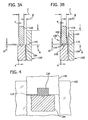
- Figure 3A is a cross-section of a portion of the crucible support and a portion of the lid;
- Figure 3B is a cross-section of a portion of the crucible support and a portion of the lid positioned on a support bracket;
- Figure 4 is a cross-section along line 4-4 in Figure 3B ;
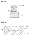
- Figure 5A is a cross-section of a portion of the lid positioned above the crucible support
- Figure 5B is a side view of the lid positioned above the crucible support
- Figure 6 is a flow diagram depicting a method of providing an inert gas flow of a melt surface in accordance with an embodiment
- Figure 7 is a cross-section of a lip formed in the lid in accordance with another embodiment
- Figure 8 is a schematic perspective view of an assembled crucible support and lid with one of the walls and a portion of the lid removed;
- Figure 9 is a top plan view of a silicon wafer
- Figure 10 is a graph showing FTIR carbon vs. the fraction solidified of various sample ingots
- Figure 11 is a graph showing maximum carbon concentration in a prime ingot portion for a given charge condition.
- Figure 12 is a schematic perspective view of an assembled crucible support and lid with one of the walls and a portion of the lid removed.
- a directional solidification furnace of this embodiment is generally referred to as 100.
- the directional solidification furnace comprises a quartz crucible 102 supported by a crucible support 103 including walls 104 (crucible support walls) and a crucible base 106. It is contemplated to use other structure or means to support the crucible. Together with a lid 112 described below, the crucible 102, crucible support base 106. The last portion to solidify is the top surface of the melt 111.
- a lid 112 of this embodiment is positioned atop the crucible 102 to contain and direct a flow of inert gas.
- the flow of inert gas is introduced to the lid 112 through an inlet tube 114 and after flowing along the top surface of the melt 111 exits through gaps (described infra in relation to Figures 3A and 3B ) beneath the top of the crucible 102 and between the walls 104 and the vertical plates 118.
- the gap may define a labyrinth or tortuous path through which the exhaust flows. This path for the exhaust reduces carbon-containing gas levels near the top surface of the melt 111.
- FIG 2 is a cross-section of the lid 112 and the surrounding structures.
- the lid 112 includes four vertical plates 118 and a horizontal plate 120. Each of the vertical plates 118 and horizontal plate 120 has an inner and an outer surface.
- the four vertical plates 118 and the horizontal plate 120 may be joined together by any suitable connection or connections, including without limitation, fasteners, pins, tongue and groove, or shiplap joints.
- the inner surfaces of the vertical plates 118 face the interior of the area enclosed by the lid 112, while the outer surfaces face the exterior of the lid.
- the length and width of the lid 112 is substantially similar to, but slightly greater than, that of the crucible 102.
- the top side of the vertical plates 118 fit into recesses 124 formed in the inner surface of the horizontal plate 120.
- the weight of the horizontal plate 120 then serves to hold the lid 112 together, while still providing for easy assembly and disassembly of the lid.
- a plurality of pins can be used to further secure the vertical plates 118 to the horizontal plate 120. The pins are inserted through holes in the vertical plates 118 and corresponding holes in the horizontal plate 120.
- the joints between the vertical plates 118 and the horizontal plates 120 inhibit the flow of inert gas through the joints. In this embodiment, any flow of inert gas through the joint is minimal and does not affect the overall flow of inert gas in the enclosed area.
- the horizontal plate 120 may be a single piece of material or may be comprised of several pieces, or interlocking pieces, e.g., for ease of manufacturing and handling.
- the vertical plates 118 and horizontal plate 120 may also be of a monolithic, single-piece design and the lid 112 is thus formed from a single piece of material.
- the horizontal plate 120 has a hole 126 formed therein for receiving the inlet tube 114.
- Some embodiments include an additional sealing ring 128 disposed above the hole 126 for tube alignment and/or sealing.
- the ring 128 and the inlet tube 114 may be made of the same or similar material as one another and as the vertical plates 118 and 120 of the lid 112.
- the sealing ring 128 has an inner surface that contacts the inlet tube 114.
- the inner diameter of the ring 128 is substantially similar to the outer diameter of the inlet tube 114.
- the inner surface of the ring 128 is tapered along its longitudinal axis for alignment. The diameter of the inner surface decreases towards the surface of the ring 128 that rests upon the horizontal plate 120.
- the inlet tube 114 is used to introduce inert gas through the horizontal plate 120 of the lid 112 into the enclosed area 130.
- the inlet tube 114 has a generally circular cross-section, although other embodiments may include differently shaped cross-sections.
- the inlet tube 114 is constructed of materials similar to those used in the construction of the other pieces of the lid 112.
- a first end 132 of the inlet tube 114 is connected to an inert gas source 134, as depicted in Figure 1 .
- the inert gas is Argon.
- a second end 136 of the inlet tube 114 penetrates the horizontal plate 120 of the lid 112 through the opening described above.
- the second end 136 of the inlet tube 114 can fit flush with the inner surface of the horizontal plate 120 or it may extend below it and into the enclosed area 130.
- the depth of the penetration of the second end 136 of the inlet tube 114 into the enclosed area 130 can be adjusted to alter the characteristics of the inert gas flow in the enclosed area 130. This adjustment does not alter the purity of the gas in the enclosed area.
- the hole 126 in the horizontal plate 120 and the inlet tube 114 are positioned in the center of the horizontal plate 120. But in other embodiments, the hole 126 and the inlet tube 114 may be positioned off-center. The position of the hole 126 and inlet tube 114 may also be adjusted to alter the flow of inert gas within the enclosed area 130. Additionally, some embodiments include multiple holes and corresponding inlet tubes in order to alter the characteristics and distribution of the inert gas flow within the enclosed area 130. Furthermore, differing size holes and corresponding inlet tubes may be used, as well as varying flow rates to manipulate the inert gas flow, according to some embodiments.
- the four vertical plates 118 are not used (see Figure 12 ).
- the horizontal plate 120 rests directly on the crucible support walls 104 and a gap is formed beneath the top of the crucible 102 in the walls 104.
- the gap may be formed by drilling, slotting or otherwise forming openings in the walls 104.
- the vertical plates 118 and horizontal plate 120 are constructed of a material that maintains its structural integrity and is minimally reactive under elevated temperatures for a prolonged period of time. Suitable materials include a form of carbon, such as graphite, and can be similar in composition to the walls 104. In some embodiments, the vertical plates 118 and 120 are constructed of high purity silicon carbide coated graphite.
- the crucible 102, inlet tube 114, and other related components are not expected to contribute significant amounts of carbon to the melt 111.
- graphite components can become brittle and be fractured by the surface chemical conversion to SiC due to the high temperature reaction with SiO or the splattering of liquid silicon thereon.
- the graphite components may be coated to prevent contributing carbon to the melt since fractured graphite surfaces can release carbon particles.
- Figure 3A is a cross-sectional view of one of the vertical plates 118 of the lid 112 and Figure 3B is a cross-sectional view of one of the vertical plates 118 of the lid 112 resting upon a support bracket 138.
- the crucible 102 is surrounded by corresponding walls 104.
- a first gap 116 and a second gap 117 are shown in Figures 3A and 3B .
- the second gap 117 is defined between the crucible 102 and the vertical plates 118.
- the second gap 117 has a width B.
- a portion of the crucible 102 extends vertically upward beyond the walls 104 by a height A.
- the height A is 38 mm and the width B is 9.5 mm, resulting in a ratio of A to B of about 4:1.
- the ratio of A to B may be between 2:1 and 11:1 (or between 2 and 11), while in other embodiments the ratio may be between 3:1 and 10:1 (or between 3 and 10), while in still other embodiments the ratio may be greater than or equal to 4:1 (or 4).
- the first gap 116 is defined between the walls 104 and the vertical plate 118.
- the first gap 116 has a width C equal to the width of the vertical plate 118 and a height D equal to the distance between the edges of the vertical plate and the wall 104.
- the width C is 9.5 mm and the height D is 1.6 mm, resulting in a ratio of C to D of 5.94 (or about 6).
- the ratio of C to D may be between 4:1 and 13:1 (or between 4 and 13), while in other embodiments the ratio may be between 5:1 and 12:1 (or between 5 and 12), while in still other embodiments the ratio may be greater than or equal to 6:1 (or 6).
- the width C and height D of first gap 116 are selected to achieve the same vertical cross-sectional area as the argon inlet area ( Figure 2 , oriented horizontally as shown). In other embodiments, the gap is selected or adjusted based on ingot carbon levels.
- the walls 104 terminate below the crucible 102, leaving a portion of the crucible exposed when the lid 112 is not in place. In other embodiments, the walls 104 do not terminate below the crucible 102 and thus no portion of the crucible is exposed when the lid is not in place.
- first gap 116 is less than about 5 millimeters, and is defined between the walls 104 and the crucible 102.
- the first gap 116 is selected to achieve the same vertical cross-sectional area as the argon inlet area, i.e., the inlet tube 114.
- the ratio of the gap cross-sectional area to the inlet cross-sectional area may be 0.5 to 10, or in another embodiment 0.8 to 1.2, or in other embodiments 1.
- the gap is selected or adjusted based on ingot carbon levels (e.g., ingot carbon measurement feedback) and/or to achieve sufficient exhaust flow speed to inhibit back-flow.
- a plurality of support brackets 138 are inserted into the walls 104, as shown in Figure 3B .
- the support brackets 138 are constructed of a suitable material that can withstand high temperatures without significant structural degradation or reaction with the atmosphere.
- the support brackets 138 are constructed from molybdenum.
- the support brackets are constructed of graphite that has been converted to SiC.
- Each of the support brackets 138 comprises a web 144 and a pin 140 extending therefrom.
- the pin 140 fits into a corresponding hole in a horizontal portion (e.g., the top) of the wall 104.
- the support bracket 138 is generally U-shaped, with two walls 142 forming a C-channel extending upward from the web 144 of the bracket. The distance between the walls 142 is substantially equal to the thickness of the vertical plates 118 of the lid 112. The vertical plates 118 of the lid 112 then fit between the two walls 142 and rest upon the web 144 of the support bracket 138.
- an alignment plus gap-setting recess may be cut into the vertical plates 118 (not shown).
- the depth of the recess can be adjusted in order to manipulate the height of the first gap 116.
- Other means of affecting the first gap 116 could also be used.
- the first gap 116 may be created by a pin that inserts into the wall 104 and the vertical lid plate 118 with a spacing washer of desired height D of the first gap 116 machined onto or placed over the pin.
- Another example is to cut the first gap 116 from the bottom edges of the lid plates 118 and include tabs (not shown) that set the first gap 116.
- the first gap 116 and second gap 117 permit egress or exhaust of the inert gas flow from the enclosed area 130.
- the total surface area of the first gap 116 is substantially equal to the cross-sectional surface area of the inlet tube 114 in order to provide for a uniform flow and pressure throughout the enclosed area 130.
- inert gas flows along a generally labyrinth-like path.
- the arrows indicating the flow path 122 are for illustrative purposes only, and the actual flow path of the inert gas can vary substantially based on any number of factors.
- inert gas is introduced through the inlet tube 114 to the enclosed area 130 defined by the horizontal plate 120 and vertical plates 118 of the lid 112, the walls 104, the crucible 102 and the top surface of the melt 111.
- the inert gas flows through the enclosed area 130 before exiting through the gaps 116, 117.
- the inert gas flow path as it exits the enclosed area 130 is labyrinth-like to minimize the back-flow of contaminants towards the surface of the melt 111.
- the inert gas travels along a nonlinear route or path through the second gap 117 and then the first gap 116.
- This nonlinear route has at least a first segment and a second segment corresponding to a path traveled through the first gap 116 and second gap 117, respectively.
- Each of the first segment and the second segment have both a lateral and a longitudinal component.
- the nonlinear route ensures that once the inert gas enters second gap 117 that the contaminants contained therein are unable to reverse course and contact the surface of the melt 111.
- the nonlinear inert gas flow path thus ensures that contaminants entrained in the inert gas flow are unable to backflow or otherwise flow backwards and contact or contaminate the surface of the melt 111.
- the inert gas flow is able to more effectively shield the melt 111 from contamination because the area surrounding the surface of the melt 111 (i.e., the enclosed area 130) is enclosed with no or substantially no leaks. Contaminants that are present in the vicinity of the surface of the melt 111 are thus purged out of the enclosed area 130 by the inert gas flow.
- Figure 4 depicts a cross-section along the line 4-4 of Figure 3B .
- Figure 5A depicts a cross-section similar to that of Figure 3B , however the support bracket 138 is not depicted, and the first gap 116 is more clearly shown.
- Figures 3A and 3B depict a first gap 116 with a uniform height
- other embodiments may have a non-uniform gap height as illustrated in Figures 5B and 8 .
- a uniform flow across the melt 111 surface aids in providing a uniform contaminant reduction profile.
- crucible 102 of this embodiment is substantially rectangular, e.g. square, in cross-section, achieving a uniform inert gas flow is difficult as the distance from the inlet tube 114 to the periphery of the lid 112 and corresponding first gap 116 is non-uniform.
- the flow e.g., the flow velocity and pressure field
- a non-uniform flow is particularly evident in the corners of the crucible 102 when the first gap 116 is of a uniform height along the periphery of the lid 112.
- the height of the first gap 116 can be increased at the corners of the lid 112 to increase inert gas flow to the corners thereof.
- the height may be increased symmetrically while in other embodiments it may be increased asymmetrically.
- Increasing the height of the first gap 116 can be achieved by increasing the height of the wall 104 or by decreasing the depth of the recess cut into the vertical plates 118 of the lid 112, or any combination of the two.
- the vertical plate 118 of the lid 112 or the top elevation of the wall 104 may have a non-uniform height profile, e.g., the height of the bottom of the vertical plate 118 may increase or the height of the wall 104 may decrease toward the corner.
- an asymmetric gap size can be designed to provide a more uniform radial gas flow velocity through the first gap 116 and a more uniform pressure in the enclosed area 130 above the silicon melt 111. In such an embodiment, designed variations in the first gap 116 are minimized because the gap affects the gas flow and the effectiveness of removal of the gaseous carbon compounds.
- Figure 8 depicts an assembled lid and crucible support 103, with the crucible 102 inside. Note that one of the crucible walls 104, one of the lid vertical plates 118, and the inlet tube 114, are omitted from Figure 8 for clarity.
- a gap i.e., the first gap 116) between the vertical plates 118 and the walls 104 is not present.
- vertical plates 118 are not used in this embodiment.
- the walls 104 instead extend upward to the horizontal plate 120 of the lid 112.
- a plurality of vent holes are thus provided in the walls 104 for the inert gas to exit therethrough.
- the vent holes are positioned in the vertical plates and/or the walls 104.
- the vent holes are sized and positioned in the walls 104 to achieve a uniform flow of inert gas above the melt 111.
- the vent holes may be substantially circular or ovate in cross-section in some embodiments.
- vent holes in the vertical plates 118 or wall 104 may be used in conjunction with the first gap 116 between the vertical plates 118 and the wall 104.
- the crucible assembly or inner assembly 105 has substantially no leaks other than vents or gaps purposefully formed therein. Likewise, the furnace 100 may have no or substantially no leaks therein.
- the crucible, the inlets and other related components are not expected to contribute significant amounts of carbon to the melt.
- Graphite components may embrittle and can be fractured by the surface chemical conversion to SiC due to high temperature reaction with SiO or splattered liquid silicon. Since fractured graphite surfaces can release carbon particles into the melt, thereby increasing carbon levels, these components may be coated to prevent contributing carbon.
- Figure 6 is a flow diagram illustrating a method of introducing and controlling an inert gas flow over a melt surface.
- the method begins at step 146 with placement of solid silicon into the crucible.
- the silicon may be in the form of solid chunks, recycled material, granular polysilicon, or powder, or any combination thereof. Dopant may also be added to the silicon or feedstock.
- the silicon should be of low carbon content if a low carbon result is desired, as virtually no carbon evaporates from the liquid melt surface.
- low carbon may be defined as below the precipitation limit for the usable portion of the ingot. At 90% solidified, the carbon should be less than 6-8 ppma in the solid, or 75-100 ppma in solution. Due to segregation, this carbon level will assure no carbon precipitation at all times during the solidification of the prime portion of the ingot. As shown in Fig. 11 , this has been achieved in testing using virgin feedstock of carbon concentration ⁇ 1.0 ppma. This level is also low enough not to enrich the recycle stream with carbon at normal recycle rates of, for example, 30%, where conventional top scrap protocol is followed (top 3-4% of ingot is not recycled).
- step 148 the lid is then placed atop the crucible assembly or support.
- the lid rests upon the support brackets positioned in the top of the crucible support walls and thereby is positioned over the crucible to form an enclosure having a labyrinth gap between the lid and the crucible and crucible support.
- inert gas is introduced to the area enclosed by the lid, melt surface, crucible, and crucible support walls.
- the gas flow in this embodiment is sufficiently pure at a sufficiently high rate to maintain low carbon levels.
- the inert gas may be introduced substantially simultaneously or slightly before the application of heat in step 152, according to some embodiments.
- the inert gas is introduced through the inlet tube in the lid.
- the inert gas serves at least two functions. First, it serves as a barrier between the melt surface and any contaminants present outside the crucible or the crucible assembly. These contaminants are often carbon monoxide gas generated from the release of carbon from the crucible support walls as they are heated or react with the crucible under elevated temperature.
- the inert gas flow also blocks other gas phase contaminants, such as iron, at elevated temperature. Note that the lid also serves to block other gas phase contaminants.
- Heat is then applied to the crucible to melt its contents in step 152.
- the heat is supplied by one or more heaters positioned around the periphery of the crucible.
- oxygen may be removed following closure (e.g., oxygen is pumped out and argon is back-filled).
- this gas flows into the vicinity of the melt surface and up between the gap between the walls 104 and the lid 112.
- the flow of carbon monoxide gas and other contaminants to the melt surface can be effectively reduced.
- the inert gas flows through the enclosed area before exiting through the gap between the walls and the vertical plates below the top edge of the crucible to form a flow labyrinth to minimize the back-flow of contaminants.
- the inert gas flow is able to effectively shield the melt surface from contamination.
- contaminants that are present in the vicinity of the melt surface are purged out of the enclosed area by the inert gas flow.
- a lip 162 is formed in the interior surface of the vertical plate 118 of the lid 112. This lip 162 serves to further inhibit the back-flow of carbon monoxide or other contaminants from the furnace volume surrounding the crucible assembly or from the reaction between the crucible and the crucible support to the melt 111. The lip further serves to protect the gaps 116, 117 from silicon particulates or splash from the meltdown either of which could inhibit subsequent disassembly or could result in damage to the parts.
- the lip 162 extends outwardly from the interior surface of the vertical plate 118 and is positioned just above a terminal end 164 of the crucible 102.
- the gap between the terminal end 164 of the crucible 102 and the lip 162 is comparable to the gap 116 between vertical plate 118 and wall 104.
- the lip 162 extends along at least a part of the length of the vertical plates 118 in a longitudinal direction and out over the terminal end 164 of the wall of the crucible 102 in the horizontal direction.
- the inert gas must then flow in between the lip 162 and the terminal end 164 of the wall of the crucible 102 before flowing out through the first gap 116 between the vertical plate 118 and the wall 104. This provides an extended labyrinth or tortuous path that provides an improved barrier to the back diffusion of carbonaceous compounds.
- the inert gas flow purges contaminants from the melt surface.
- contaminants e.g., carbon monoxide and other carbon compounds including carbon
- the inert gas flow serves to purge them from the melt surface.
- the contaminants are effectively transported by the flow of inert gas from the melt surface and out through the gap between the vertical plates of the lid and the crucible support walls.
- about 6.6 liters/hour of carbon monoxide is generated in the furnace.
- the inert gas is introduced at a nominal rate of 50 SLPM or a scaled (operating conditions) rate of about 472 liters/minute at silicon melting temperature (1400 degrees C) and a pressure of 600 mBar. Assuming that no other sources of carbon monoxide are present, then the gaseous carbonaceous concentration by volume in the gap is at about 0.023%.
- the furnace results in less than 0.03% gaseous carbonaceous compounds by volume, and in another embodiment less than .5% or in still another embodiment less than 5%.
- the gas After the gas exits from the enclosed area through the gaps, it may be collected and recycled for later reuse. Alternatively, the gas may be disposed of by safe venting back into the environment.
- the process of solidifying can begin (step 156).
- the ingot first solidifies in a lower area, and the solidification proceeds in a direction roughly normal to a solidification front.
- thermal energy or heat
- the melt then begins to solidify in the bottom of the crucible and the solidification proceeds in a direction towards the top of the melt surface.
- the solidified ingot is cooled in step 157.
- the lid is removed in step 158 and the ingot is removed from the crucible in step 160.
- the ingot is then sliced into multi-crystalline wafers, such as wafer W shown in Figure 9 , as is customary in the industry.
- the described embodiments provide an apparatus and method to direct a flow of inert gas above a melt surface to reduce or inhibit carbon contamination in a melt or ingot.
- ingots produced by the new method and systems have substantially less carbon than those produced by prior art methods.
- a prior art process using 30% recycled polysilicon (poly) feedstock has an initial melt carbon concentration of 48 ppma, a relatively high carbon content which results in carbon precipitation in the ingot (the middle of the ingot) as shown.
- Using virgin poly of less than 1.0 ppma in the prior art process results in an initial melt concentration of 19 ppma as shown.
- virgin poly and the Figures 1-5 embodiment without an air leak yielded the lowest carbon content.
- the carbon concentration measurement indicates only non-precipitated carbon in the silicon.
- the FTIR carbon measurement remains near the precipitation limit once precipitation begins.
- the wafer or wafers produced by this process will have lower carbon than prior art wafers, as illustrated in Figures 10 and 11 .
- the wafers are therefore less likely to have SiC precipitates incorporated which can cause electrical shunts in products produced therefrom, such as solar cells.
- Even using a typical recycle rate of, for example, 32%, the maximum predicted prime ingot carbon level will not exceed the precipitation level of 6.0 ppma, as predicted by the segregation model plotted in Figure 11 .
Landscapes
- Chemical & Material Sciences (AREA)
- Engineering & Computer Science (AREA)
- Crystallography & Structural Chemistry (AREA)
- Materials Engineering (AREA)
- Metallurgy (AREA)
- Organic Chemistry (AREA)
- Silicon Compounds (AREA)
- Crystals, And After-Treatments Of Crystals (AREA)
Description
- This invention generally relates to directional solidification furnaces and, more specifically, to an apparatus and method for directing an inert gas flow into the furnace.
- Directional solidification furnaces are often used in the production of multi-crystalline silicon ingots. Raw silicon is first loaded into a quartz crucible. The silicon can take the form of solid chunks, recycled polysilicon, silicon dust, or a combination of them. The crucible is typically constructed of quartz, or another suitable material that can withstand high temperatures while remaining essentially inert. The crucible is typically a five-sided box, with the top of the box being open to the atmosphere within the furnace. The quartz crucible is supported by graphite support walls that add structural rigidity to the crucible.
- After the crucible has been charged with silicon, the area surrounding the crucible is sealed from the outside ambient environment. To aid in the separation of the crucible from the outside environment, the crucible is placed within a containment vessel that forms part of the furnace. The pressure within the containment vessel is then reduced. The content of the atmosphere within the containment vessel can also be monitored and controlled.
- The crucible and the charge are then heated to a temperature sufficient to melt the silicon. After the charge has completely melted it is cooled at a controlled rate to achieve a directional solidification structure. The controlled rate of cooling is established by any combination of reducing the amount and location of heat applied by the radiant heaters, the movement of or the opening of a heat vent in insulation surrounding the crucible, or the circulation of a cooling medium through a cooling plate. Any of these methods transfer heat away from the surface of the crucible. If the rate of cooling of the bottom of the crucible is greater than that of the sides of the crucible, then a relatively flat, horizontal solidification isotherm with predominately axial thermal gradients is generated. The ingot thereby solidifies in the region closest to the cooler side of the crucible and proceeds in a direction away from that side of the crucible. The last portion of the melt to solidify is generally at the top of the ingot.
- A significant concern in the production of multi-crystalline silicon ingots in directional solidification furnaces is the contamination of the ingot with impurities. An entry point of contamination is often at the melt surface. Gaseous or solid carbon or other contaminants present in the containment vessel enter at the melt surface and are at least partially absorbed by the melt, and are subsequently incorporated into the ingot upon solidification sometimes as a precipitated compound. Some of the sources of carbon contamination are carbon monoxide gas formed when the crucible and walls are heated, as well as oxygen-containing compounds contacting heated insulation and graphite or the deterioration of friable insulation surrounding the walls and the interior of the furnace enclosure resulting in particulate carbon contamination. The carbon monoxide gas is formed in the following reaction: SiO(g) + C(s) => SiC(s) + CO(g) and O2(g) + 2*C(s) => 2*CO(g) where the source of the gaseous SiO can be evaporation from the free silicon melt surface or decomposition of the crucible by the reaction 2*SiO2(g) => 2*SiO(g) + O2(g), and the oxygen may originate from air remaining in the furnace or air leaks into the furnace. Decomposition of the quartz crucible by the adjacent crucible support is also an important source of carbon containing species. This occurs by a reaction such as SiO2 + 2*C(s) => SiC(s) + CO(g) The carbon monoxide or carbon dioxide gas (created from any source) reacts with the melt surface as represented by the following reactions: Si(l) + CO(g) → SiO(g) + C or Si(l) + CO2(g) => 2*SiO(g) + C.
- Carbon precipitates in silicon ingots cause undesirable electrical shunts in the products that are eventually fabricated from the ingots, such as solar cells. Carbon also contaminates the recycle stream of silicon, as unused or unsatisfactory ingots are often recycled to form new ingots. Consequently, reducing the carbon contamination of the melt decreases the carbon contamination levels of the recycle stream.
-
EP 1 384 538 A1DE 10 2006 017 622 A1 describes a process for manufacturing multi-crystalline silicon by vertical-gradient-freeze procedure.WO 2007/148985 A1 refers to a device and method for production of ingots of semiconductor grade silicon, where the presence of oxygen in the hot zone is substantially reduced or eliminated by employing materials void of oxides in the hot zone of the melting and crystallization process.EP 1 048 758 A1US 2002/0139297 A1 describe methods for producing a crystal silicon which enables low cost and easy production of polycrystalline silicon having a high quality with a low impurity content and a high crystallinity. - Attempts have been made to introduce an inert gas flow in the furnace, but they have not been completely satisfactory due to an ineffective flow path. Accordingly, an efficient and effective apparatus and method are needed to introduce an inert gas flow to reduce contamination levels in the ingot.
- In one aspect, a directional solidification furnace comprises a crucible for holding molten silicon and a lid covering the crucible and forming an enclosure over the molten silicon. The crucible also comprises an inlet in the lid for introducing inert gas above the molten silicon to inhibit contamination of the molten silicon.
Brackets are disposed between the crucible and the lid to support the lid and form a plurality of gaps between a periphery of the crucible and a periphery of the lid for venting the inert gas from above the molten silicon. - In another aspect, a method of manufacturing a multi-crystalline ingot comprises placing solid polysilicon into a crucible and placing a lid over the crucible to form an enclosure having a labyrinth gap between the lid and the crucible. The lid is supported by brackets disposed between the crucible and the lid. The method further comprises applying heat to melt the polysilicon. The method also comprises introducing inert gas to the enclosure such that the gas purges contaminants from the enclosure and exits the enclosure only through the gap. The method also comprises solidifying the molten polysilicon to form the ingot.
- Various refinements exist of the features noted in relation to the above-mentioned aspects. Further features may also be incorporated in the above-mentioned aspects as well. These refinements and additional features may exist individually or in any combination. For instance, various features discussed below in relation to any of the illustrated embodiments may be incorporated into any of the above-described aspects, alone or in any combination.
-
Figure 1 is a partially schematic cross-section of a directional solidification furnace in accordance with one embodiment; -
Figure 2 is a cross-section of a lid, crucible, and crucible support ofFig. 1 , and schematically illustrates the flow of inert gas through the enclosed space above the silicon melt; -
Figure 3A is a cross-section of a portion of the crucible support and a portion of the lid; -
Figure 3B is a cross-section of a portion of the crucible support and a portion of the lid positioned on a support bracket; -
Figure 4 is a cross-section along line 4-4 inFigure 3B ; -
Figure 5A is a cross-section of a portion of the lid positioned above the crucible support; -
Figure 5B is a side view of the lid positioned above the crucible support; -
Figure 6 is a flow diagram depicting a method of providing an inert gas flow of a melt surface in accordance with an embodiment; -
Figure 7 is a cross-section of a lip formed in the lid in accordance with another embodiment; -
Figure 8 is a schematic perspective view of an assembled crucible support and lid with one of the walls and a portion of the lid removed; -
Figure 9 is a top plan view of a silicon wafer; -
Figure 10 is a graph showing FTIR carbon vs. the fraction solidified of various sample ingots; -
Figure 11 is a graph showing maximum carbon concentration in a prime ingot portion for a given charge condition; and -
Figure 12 is a schematic perspective view of an assembled crucible support and lid with one of the walls and a portion of the lid removed. - Referring to
Figure 1 , a directional solidification furnace of this embodiment is generally referred to as 100. The directional solidification furnace comprises aquartz crucible 102 supported by acrucible support 103 including walls 104 (crucible support walls) and acrucible base 106. It is contemplated to use other structure or means to support the crucible. Together with alid 112 described below, thecrucible 102,crucible support base 106. The last portion to solidify is the top surface of themelt 111. - A
lid 112 of this embodiment is positioned atop thecrucible 102 to contain and direct a flow of inert gas. As shown inFigure 2 , the flow of inert gas is introduced to thelid 112 through aninlet tube 114 and after flowing along the top surface of themelt 111 exits through gaps (described infra in relation toFigures 3A and 3B ) beneath the top of thecrucible 102 and between thewalls 104 and thevertical plates 118. As further described below and as shown inFigure 2 , the gap may define a labyrinth or tortuous path through which the exhaust flows. This path for the exhaust reduces carbon-containing gas levels near the top surface of themelt 111. -
Figure 2 is a cross-section of thelid 112 and the surrounding structures. Thelid 112 includes fourvertical plates 118 and ahorizontal plate 120. Each of thevertical plates 118 andhorizontal plate 120 has an inner and an outer surface. The fourvertical plates 118 and thehorizontal plate 120 may be joined together by any suitable connection or connections, including without limitation, fasteners, pins, tongue and groove, or shiplap joints. The inner surfaces of thevertical plates 118 face the interior of the area enclosed by thelid 112, while the outer surfaces face the exterior of the lid. The length and width of thelid 112 is substantially similar to, but slightly greater than, that of thecrucible 102. - In one embodiment, the top side of the
vertical plates 118 fit intorecesses 124 formed in the inner surface of thehorizontal plate 120. The weight of thehorizontal plate 120 then serves to hold thelid 112 together, while still providing for easy assembly and disassembly of the lid. In some embodiments, a plurality of pins can be used to further secure thevertical plates 118 to thehorizontal plate 120. The pins are inserted through holes in thevertical plates 118 and corresponding holes in thehorizontal plate 120. The joints between thevertical plates 118 and thehorizontal plates 120 inhibit the flow of inert gas through the joints. In this embodiment, any flow of inert gas through the joint is minimal and does not affect the overall flow of inert gas in the enclosed area. - The
horizontal plate 120 may be a single piece of material or may be comprised of several pieces, or interlocking pieces, e.g., for ease of manufacturing and handling. Thevertical plates 118 andhorizontal plate 120 may also be of a monolithic, single-piece design and thelid 112 is thus formed from a single piece of material. Thehorizontal plate 120 has ahole 126 formed therein for receiving theinlet tube 114. Some embodiments include anadditional sealing ring 128 disposed above thehole 126 for tube alignment and/or sealing. Thering 128 and theinlet tube 114 may be made of the same or similar material as one another and as thevertical plates lid 112. The sealingring 128 has an inner surface that contacts theinlet tube 114. The inner diameter of thering 128 is substantially similar to the outer diameter of theinlet tube 114. In some embodiments the inner surface of thering 128 is tapered along its longitudinal axis for alignment. The diameter of the inner surface decreases towards the surface of thering 128 that rests upon thehorizontal plate 120. - The
inlet tube 114 is used to introduce inert gas through thehorizontal plate 120 of thelid 112 into theenclosed area 130. Theinlet tube 114 has a generally circular cross-section, although other embodiments may include differently shaped cross-sections. Theinlet tube 114 is constructed of materials similar to those used in the construction of the other pieces of thelid 112. - A
first end 132 of theinlet tube 114 is connected to aninert gas source 134, as depicted inFigure 1 . In some embodiments, the inert gas is Argon.
As shown inFigure 2 , asecond end 136 of theinlet tube 114 penetrates thehorizontal plate 120 of thelid 112 through the opening described above. Thesecond end 136 of theinlet tube 114 can fit flush with the inner surface of thehorizontal plate 120 or it may extend below it and into theenclosed area 130. The depth of the penetration of thesecond end 136 of theinlet tube 114 into theenclosed area 130 can be adjusted to alter the characteristics of the inert gas flow in theenclosed area 130. This adjustment does not alter the purity of the gas in the enclosed area. - In this embodiment, the
hole 126 in thehorizontal plate 120 and theinlet tube 114 are positioned in the center of thehorizontal plate 120. But in other embodiments, thehole 126 and theinlet tube 114 may be positioned off-center. The position of thehole 126 andinlet tube 114 may also be adjusted to alter the flow of inert gas within theenclosed area 130. Additionally, some embodiments include multiple holes and corresponding inlet tubes in order to alter the characteristics and distribution of the inert gas flow within theenclosed area 130. Furthermore, differing size holes and corresponding inlet tubes may be used, as well as varying flow rates to manipulate the inert gas flow, according to some embodiments. - In other embodiments the four
vertical plates 118 are not used (seeFigure 12 ). In these embodiments, thehorizontal plate 120 rests directly on thecrucible support walls 104 and a gap is formed beneath the top of thecrucible 102 in thewalls 104. For example, the gap may be formed by drilling, slotting or otherwise forming openings in thewalls 104. - Returning now to the embodiment of
Figures 1-4 , thevertical plates 118 andhorizontal plate 120 are constructed of a material that maintains its structural integrity and is minimally reactive under elevated temperatures for a prolonged period of time. Suitable materials include a form of carbon, such as graphite, and can be similar in composition to thewalls 104. In some embodiments, thevertical plates - The
crucible 102,inlet tube 114, and other related components are not expected to contribute significant amounts of carbon to themelt 111. However, graphite components can become brittle and be fractured by the surface chemical conversion to SiC due to the high temperature reaction with SiO or the splattering of liquid silicon thereon. The graphite components may be coated to prevent contributing carbon to the melt since fractured graphite surfaces can release carbon particles. -
Figure 3A is a cross-sectional view of one of thevertical plates 118 of thelid 112 andFigure 3B is a cross-sectional view of one of thevertical plates 118 of thelid 112 resting upon asupport bracket 138. As described above, thecrucible 102 is surrounded by correspondingwalls 104. Afirst gap 116 and a second gap 117 are shown inFigures 3A and 3B . The second gap 117 is defined between thecrucible 102 and thevertical plates 118. The second gap 117 has a width B. A portion of thecrucible 102 extends vertically upward beyond thewalls 104 by a height A. In one embodiment, the height A is 38 mm and the width B is 9.5 mm, resulting in a ratio of A to B of about 4:1. In other embodiments, the ratio of A to B may be between 2:1 and 11:1 (or between 2 and 11), while in other embodiments the ratio may be between 3:1 and 10:1 (or between 3 and 10), while in still other embodiments the ratio may be greater than or equal to 4:1 (or 4). - The
first gap 116 is defined between thewalls 104 and thevertical plate 118. Thefirst gap 116 has a width C equal to the width of thevertical plate 118 and a height D equal to the distance between the edges of the vertical plate and thewall 104. In one embodiment, the width C is 9.5 mm and the height D is 1.6 mm, resulting in a ratio of C to D of 5.94 (or about 6). In other embodiments, the ratio of C to D may be between 4:1 and 13:1 (or between 4 and 13), while in other embodiments the ratio may be between 5:1 and 12:1 (or between 5 and 12), while in still other embodiments the ratio may be greater than or equal to 6:1 (or 6). - In some embodiments, the width C and height D of
first gap 116 are selected to achieve the same vertical cross-sectional area as the argon inlet area (Figure 2 , oriented horizontally as shown). In other embodiments, the gap is selected or adjusted based on ingot carbon levels. In the illustrated embodiments, thewalls 104 terminate below thecrucible 102, leaving a portion of the crucible exposed when thelid 112 is not in place. In other embodiments, thewalls 104 do not terminate below thecrucible 102 and thus no portion of the crucible is exposed when the lid is not in place. - In another embodiment,
first gap 116 is less than about 5 millimeters, and is defined between thewalls 104 and thecrucible 102. In this embodiment, thefirst gap 116 is selected to achieve the same vertical cross-sectional area as the argon inlet area, i.e., theinlet tube 114. The ratio of the gap cross-sectional area to the inlet cross-sectional area may be 0.5 to 10, or in another embodiment 0.8 to 1.2, or inother embodiments 1. In this embodiment, the gap is selected or adjusted based on ingot carbon levels (e.g., ingot carbon measurement feedback) and/or to achieve sufficient exhaust flow speed to inhibit back-flow. - A plurality of
support brackets 138 are inserted into thewalls 104, as shown inFigure 3B . Thesupport brackets 138 are constructed of a suitable material that can withstand high temperatures without significant structural degradation or reaction with the atmosphere. In one embodiment, thesupport brackets 138 are constructed from molybdenum. In another embodiment, the support brackets are constructed of graphite that has been converted to SiC. - Each of the
support brackets 138 comprises aweb 144 and apin 140 extending therefrom. Thepin 140 fits into a corresponding hole in a horizontal portion (e.g., the top) of thewall 104. Thesupport bracket 138 is generally U-shaped, with twowalls 142 forming a C-channel extending upward from theweb 144 of the bracket. The distance between thewalls 142 is substantially equal to the thickness of thevertical plates 118 of thelid 112. Thevertical plates 118 of thelid 112 then fit between the twowalls 142 and rest upon theweb 144 of thesupport bracket 138. Where thevertical plates 118 mate to the twowalls 142, an alignment plus gap-setting recess (i.e., a bridle joint arrangement) may be cut into the vertical plates 118 (not shown). This permits the height D of thefirst gap 116 to be reduced, while still maintaining the same thickness of theweb 144 of thesupport bracket 138. The depth of the recess can be adjusted in order to manipulate the height of thefirst gap 116. Other means of affecting thefirst gap 116 could also be used. For example, thefirst gap 116 may be created by a pin that inserts into thewall 104 and thevertical lid plate 118 with a spacing washer of desired height D of thefirst gap 116 machined onto or placed over the pin. Another example is to cut thefirst gap 116 from the bottom edges of thelid plates 118 and include tabs (not shown) that set thefirst gap 116. - The
first gap 116 and second gap 117 permit egress or exhaust of the inert gas flow from theenclosed area 130. The total surface area of thefirst gap 116 is substantially equal to the cross-sectional surface area of theinlet tube 114 in order to provide for a uniform flow and pressure throughout theenclosed area 130. - The general path of the flow of inert gas within the
enclosed area 130 is depicted inFig. 2 . The inert gas flows along a generally labyrinth-like path. The arrows indicating theflow path 122 are for illustrative purposes only, and the actual flow path of the inert gas can vary substantially based on any number of factors. Generally, inert gas is introduced through theinlet tube 114 to theenclosed area 130 defined by thehorizontal plate 120 andvertical plates 118 of thelid 112, thewalls 104, thecrucible 102 and the top surface of themelt 111. The inert gas flows through theenclosed area 130 before exiting through thegaps 116, 117. - The inert gas flow path as it exits the
enclosed area 130 is labyrinth-like to minimize the back-flow of contaminants towards the surface of themelt 111. As more clearly shown inFigures 3A and 3B , the inert gas travels along a nonlinear route or path through the second gap 117 and then thefirst gap 116. This nonlinear route has at least a first segment and a second segment corresponding to a path traveled through thefirst gap 116 and second gap 117, respectively. Each of the first segment and the second segment have both a lateral and a longitudinal component. The nonlinear route ensures that once the inert gas enters second gap 117 that the contaminants contained therein are unable to reverse course and contact the surface of themelt 111. The nonlinear inert gas flow path thus ensures that contaminants entrained in the inert gas flow are unable to backflow or otherwise flow backwards and contact or contaminate the surface of themelt 111. - In some embodiments, the inert gas flow is able to more effectively shield the
melt 111 from contamination because the area surrounding the surface of the melt 111 (i.e., the enclosed area 130) is enclosed with no or substantially no leaks. Contaminants that are present in the vicinity of the surface of themelt 111 are thus purged out of theenclosed area 130 by the inert gas flow. -
Figure 4 depicts a cross-section along the line 4-4 ofFigure 3B .Figure 5A depicts a cross-section similar to that ofFigure 3B , however thesupport bracket 138 is not depicted, and thefirst gap 116 is more clearly shown. - While
Figures 3A and 3B depict afirst gap 116 with a uniform height, other embodiments may have a non-uniform gap height as illustrated inFigures 5B and8 . A uniform flow across themelt 111 surface aids in providing a uniform contaminant reduction profile. However, sincecrucible 102 of this embodiment is substantially rectangular, e.g. square, in cross-section, achieving a uniform inert gas flow is difficult as the distance from theinlet tube 114 to the periphery of thelid 112 and correspondingfirst gap 116 is non-uniform. By altering the gap height along the periphery of thelid 112, the flow (e.g., the flow velocity and pressure field) of the inert gas can be manipulated. A non-uniform flow is particularly evident in the corners of thecrucible 102 when thefirst gap 116 is of a uniform height along the periphery of thelid 112. - For instance, the height of the
first gap 116 can be increased at the corners of thelid 112 to increase inert gas flow to the corners thereof. In some embodiments, the height may be increased symmetrically while in other embodiments it may be increased asymmetrically. Increasing the height of thefirst gap 116 can be achieved by increasing the height of thewall 104 or by decreasing the depth of the recess cut into thevertical plates 118 of thelid 112, or any combination of the two. To change the gap height asymmetrically as shown inFigures 5B and8 , thevertical plate 118 of thelid 112 or the top elevation of thewall 104 may have a non-uniform height profile, e.g., the height of the bottom of thevertical plate 118 may increase or the height of thewall 104 may decrease toward the corner. In this embodiment, an asymmetric gap size can be designed to provide a more uniform radial gas flow velocity through thefirst gap 116 and a more uniform pressure in theenclosed area 130 above thesilicon melt 111. In such an embodiment, designed variations in thefirst gap 116 are minimized because the gap affects the gas flow and the effectiveness of removal of the gaseous carbon compounds. -
Figure 8 depicts an assembled lid andcrucible support 103, with thecrucible 102 inside. Note that one of thecrucible walls 104, one of the lidvertical plates 118, and theinlet tube 114, are omitted fromFigure 8 for clarity. - In alternative embodiments such as those illustrated in
Figure 12 , a gap (i.e., the first gap 116) between thevertical plates 118 and thewalls 104 is not present. Furthermore,vertical plates 118 are not used in this embodiment. Thewalls 104 instead extend upward to thehorizontal plate 120 of thelid 112. A plurality of vent holes are thus provided in thewalls 104 for the inert gas to exit therethrough. In other embodiments that includevertical plates 118 as shown in the embodiments ofFigures 1-5 , the vent holes are positioned in the vertical plates and/or thewalls 104.
In the embodiment ofFigure 12 , the vent holes are sized and positioned in thewalls 104 to achieve a uniform flow of inert gas above themelt 111. The vent holes may be substantially circular or ovate in cross-section in some embodiments. Further, vent holes in thevertical plates 118 orwall 104 may be used in conjunction with thefirst gap 116 between thevertical plates 118 and thewall 104. - In one embodiment, the crucible assembly or
inner assembly 105 has substantially no leaks other than vents or gaps purposefully formed therein. Likewise, thefurnace 100 may have no or substantially no leaks therein. - The crucible, the inlets and other related components are not expected to contribute significant amounts of carbon to the melt. Graphite components, however, may embrittle and can be fractured by the surface chemical conversion to SiC due to high temperature reaction with SiO or splattered liquid silicon. Since fractured graphite surfaces can release carbon particles into the melt, thereby increasing carbon levels, these components may be coated to prevent contributing carbon.
-
Figure 6 is a flow diagram illustrating a method of introducing and controlling an inert gas flow over a melt surface. The method begins atstep 146 with placement of solid silicon into the crucible. The silicon may be in the form of solid chunks, recycled material, granular polysilicon, or powder, or any combination thereof. Dopant may also be added to the silicon or feedstock. The silicon should be of low carbon content if a low carbon result is desired, as virtually no carbon evaporates from the liquid melt surface. - For the purpose of solar cell fabrication, low carbon may be defined as below the precipitation limit for the usable portion of the ingot. At 90% solidified, the carbon should be less than 6-8 ppma in the solid, or 75-100 ppma in solution. Due to segregation, this carbon level will assure no carbon precipitation at all times during the solidification of the prime portion of the ingot. As shown in
Fig. 11 , this has been achieved in testing using virgin feedstock of carbon concentration < 1.0 ppma. This level is also low enough not to enrich the recycle stream with carbon at normal recycle rates of, for example, 30%, where conventional top scrap protocol is followed (top 3-4% of ingot is not recycled). - In
step 148 the lid is then placed atop the crucible assembly or support. The lid rests upon the support brackets positioned in the top of the crucible support walls and thereby is positioned over the crucible to form an enclosure having a labyrinth gap between the lid and the crucible and crucible support. - In
step 150 inert gas is introduced to the area enclosed by the lid, melt surface, crucible, and crucible support walls. The gas flow in this embodiment is sufficiently pure at a sufficiently high rate to maintain low carbon levels. The inert gas may be introduced substantially simultaneously or slightly before the application of heat instep 152, according to some embodiments. The inert gas is introduced through the inlet tube in the lid. The inert gas serves at least two functions. First, it serves as a barrier between the melt surface and any contaminants present outside the crucible or the crucible assembly. These contaminants are often carbon monoxide gas generated from the release of carbon from the crucible support walls as they are heated or react with the crucible under elevated temperature. The inert gas flow also blocks other gas phase contaminants, such as iron, at elevated temperature. Note that the lid also serves to block other gas phase contaminants. - Heat is then applied to the crucible to melt its contents in
step 152. The heat is supplied by one or more heaters positioned around the periphery of the crucible. Also, oxygen may be removed following closure (e.g., oxygen is pumped out and argon is back-filled). - In
step 154, this gas flows into the vicinity of the melt surface and up between the gap between thewalls 104 and thelid 112. By directing inert gas down from the inlet tube and towards the melt surface and out through the gap between the vertical plates of the lid and the crucible support wall, the flow of carbon monoxide gas and other contaminants to the melt surface can be effectively reduced. The inert gas flows through the enclosed area before exiting through the gap between the walls and the vertical plates below the top edge of the crucible to form a flow labyrinth to minimize the back-flow of contaminants. By enclosing the area surrounding the melt surface, the inert gas flow is able to effectively shield the melt surface from contamination. In addition, contaminants that are present in the vicinity of the melt surface (the contaminants may be generated within the enclosed area) are purged out of the enclosed area by the inert gas flow. - As shown in the embodiment of
Figure 7 , alip 162 is formed in the interior surface of thevertical plate 118 of thelid 112. Thislip 162 serves to further inhibit the back-flow of carbon monoxide or other contaminants from the furnace volume surrounding the crucible assembly or from the reaction between the crucible and the crucible support to themelt 111. The lip further serves to protect thegaps 116, 117 from silicon particulates or splash from the meltdown either of which could inhibit subsequent disassembly or could result in damage to the parts. Thelip 162 extends outwardly from the interior surface of thevertical plate 118 and is positioned just above aterminal end 164 of thecrucible 102. The gap between theterminal end 164 of thecrucible 102 and thelip 162 is comparable to thegap 116 betweenvertical plate 118 andwall 104. Thelip 162 extends along at least a part of the length of thevertical plates 118 in a longitudinal direction and out over theterminal end 164 of the wall of thecrucible 102 in the horizontal direction. The inert gas must then flow in between thelip 162 and theterminal end 164 of the wall of thecrucible 102 before flowing out through thefirst gap 116 between thevertical plate 118 and thewall 104. This provides an extended labyrinth or tortuous path that provides an improved barrier to the back diffusion of carbonaceous compounds. - Returning now to
Figure 6 , secondly, the inert gas flow purges contaminants from the melt surface. In the event that contaminants, e.g., carbon monoxide and other carbon compounds including carbon, are present in the vicinity of the melt surface, the inert gas flow serves to purge them from the melt surface. The contaminants are effectively transported by the flow of inert gas from the melt surface and out through the gap between the vertical plates of the lid and the crucible support walls. - In one example, about 6.6 liters/hour of carbon monoxide is generated in the furnace. The inert gas is introduced at a nominal rate of 50 SLPM or a scaled (operating conditions) rate of about 472 liters/minute at silicon melting temperature (1400 degrees C) and a pressure of 600 mBar. Assuming that no other sources of carbon monoxide are present, then the gaseous carbonaceous concentration by volume in the gap is at about 0.023%. In another embodiment, the furnace results in less than 0.03% gaseous carbonaceous compounds by volume, and in another embodiment less than .5% or in still another embodiment less than 5%.
- After the gas exits from the enclosed area through the gaps, it may be collected and recycled for later reuse. Alternatively, the gas may be disposed of by safe venting back into the environment.
- Once the silicon has melted, the process of solidifying can begin (step 156). As described above, in directional solidification furnaces, the ingot first solidifies in a lower area, and the solidification proceeds in a direction roughly normal to a solidification front. As thermal energy (or heat) is removed from the bottom of the crucible, for example by a heat exchanger described above or by other means, the melt then begins to solidify in the bottom of the crucible and the solidification proceeds in a direction towards the top of the melt surface. After the silicon has solidified into an ingot, e.g., a multi-crystalline ingot, the solidified ingot is cooled in
step 157. The lid is removed instep 158 and the ingot is removed from the crucible instep 160. The ingot is then sliced into multi-crystalline wafers, such as wafer W shown inFigure 9 , as is customary in the industry. - The described embodiments provide an apparatus and method to direct a flow of inert gas above a melt surface to reduce or inhibit carbon contamination in a melt or ingot.
- As shown in
Figure 10 , ingots produced by the new method and systems have substantially less carbon than those produced by prior art methods. A prior art process using 30% recycled polysilicon (poly) feedstock has an initial melt carbon concentration of 48 ppma, a relatively high carbon content which results in carbon precipitation in the ingot (the middle of the ingot) as shown. Using virgin poly of less than 1.0 ppma in the prior art process results in an initial melt concentration of 19 ppma as shown. Finally, using virgin poly and theFigures 1-5 embodiment without an air leak yielded the lowest carbon content. The carbon concentration measurement indicates only non-precipitated carbon in the silicon. Thus, the FTIR carbon measurement remains near the precipitation limit once precipitation begins. - The wafer or wafers produced by this process will have lower carbon than prior art wafers, as illustrated in
Figures 10 and11 . The wafers are therefore less likely to have SiC precipitates incorporated which can cause electrical shunts in products produced therefrom, such as solar cells. Even using a typical recycle rate of, for example, 32%, the maximum predicted prime ingot carbon level will not exceed the precipitation level of 6.0 ppma, as predicted by the segregation model plotted inFigure 11 . - When introducing elements of the present invention or the embodiment(s) thereof, the articles "a", "an", "the" and "said" are intended to mean that there are one or more of the elements. The terms "comprising", "including" and "having" are intended to be inclusive and mean that there may be additional elements other than the listed elements. The use of terms indicating a particular orientation (e.g., "top", "bottom", "side", etc.) is for convenience of description and does not require any particular orientation of the item described.
Claims (12)
- A directional solidification furnace (100) comprising:a crucible (102) for holding molten silicon (111);a lid (112) covering the crucible (102) and forming an enclosure (130) over the molten silicon (111);brackets (138) disposed between the crucible (102) and the lid (112) to support the lid (112) and form a plurality of gaps (116, 117) between a periphery of the crucible (102) and a periphery of the lid (112) for venting the inert gas from above the molten silicon (111); andan inlet in the lid (112) for introducing inert gas above the molten silicon (111) to inhibit contamination of the molten silicon (111).
- The furnace (100) of claim 1 further comprising a crucible support (103) including a plurality of holes formed in the crucible support walls (104) for venting the inert gas from above the molten silicon (111) and facilitating the uniform flow of inert gas over the molten silicon (111).
- The furnace (100) of claim 1 wherein the lid (112) comprises one or more plates (118, 120) of heat-resistant material including silicon carbide-coated graphite.
- The furnace (100) of claim 1 wherein the inlet includes an inlet tube (114) and a sealing ring (128).
- The furnace (100) of claim 4 wherein the inlet tube (114) and sealing ring (128) are made of silicon carbide-coated graphite.
- The furnace (100) of claim 1 wherein the lid (112) is made of at least four pieces of heat resistant material.
- The furnace (100) of claim 6 wherein the lid (112) includes a horizontal plate (120) and four vertical side walls (104).
- The furnace (100) of claim 1 wherein the lid (112) includes an internal horizontal lip (162) for inhibiting back-flow of contamination and protecting the plurality of gaps (116, 117) from molten silicon (111).
- The furnace (100) of claim 1 wherein the crucible (102) is square in cross-section.
- A method of manufacturing a multi-crystalline ingot comprising:placing solid polysilicon into a crucible (102);placing a lid (112) over the crucible (102) to form an enclosure (130) having a labyrinth gap (116, 117) between the lid (112) and the crucible (102), the lid (112) supported by brackets (138) disposed between the crucible (102) and the lid (112);applying heat to melt the polysilicon;introducing inert gas through an inlet tube (114) in the lid (112) to the enclosure (130) such that the gas purges contaminants from the enclosure (130) and exits the enclosure (130) only through the gap (116, 117);solidifying the molten polysilicon to form the ingot.
- The method of claim 10 wherein solidifying the polysilicon includes removing thermal energy from the crucible (102).
- The method of claim 11 further comprising at least one of:purging oxygen from the enclosure (130) prior to introducing inert gas;collecting gas as the gas exits the enclosure (130);recycling the collected gas; andslicing the ingot into wafers.
Applications Claiming Priority (2)
| Application Number | Priority Date | Filing Date | Title |
|---|---|---|---|
| US9857008P | 2008-09-19 | 2008-09-19 | |
| PCT/US2009/057602 WO2010033885A1 (en) | 2008-09-19 | 2009-09-19 | Directional solidification furnace for reducing melt contamination and reducing wafer contamination |
Publications (2)
| Publication Number | Publication Date |
|---|---|
| EP2334847A1 EP2334847A1 (en) | 2011-06-22 |
| EP2334847B1 true EP2334847B1 (en) | 2013-06-19 |
Family
ID=41398514
Family Applications (1)
| Application Number | Title | Priority Date | Filing Date |
|---|---|---|---|
| EP09792746.1A Not-in-force EP2334847B1 (en) | 2008-09-19 | 2009-09-19 | Directional solidification furnace and method for reducing melt contamination and reducing wafer contamination |
Country Status (7)
| Country | Link |
|---|---|
| US (2) | US8317920B2 (en) |
| EP (1) | EP2334847B1 (en) |
| JP (1) | JP2012502879A (en) |
| KR (1) | KR101370180B1 (en) |
| CN (1) | CN102159754B (en) |
| TW (1) | TWI485295B (en) |
| WO (1) | WO2010033885A1 (en) |
Families Citing this family (26)
| Publication number | Priority date | Publication date | Assignee | Title |
|---|---|---|---|---|
| CN101949056B (en) * | 2010-09-25 | 2013-01-30 | 王敬 | Directional solidification furnace with heat preservation part at bottom of side wall of crucible |
| CN102453961A (en) * | 2010-10-20 | 2012-05-16 | 中央大学 | Thermal field device |
| CN102453959A (en) * | 2010-10-20 | 2012-05-16 | 中央大学 | Airflow guiding device of crystal growth furnace |
| CN102453952B (en) * | 2010-10-20 | 2014-12-31 | 中央大学 | Gas supply device for crystal growth furnace |
| US8926751B2 (en) * | 2010-12-02 | 2015-01-06 | National Central University | Gas flow guiding device for use in crystal-growing furnace |
| US20120137962A1 (en) * | 2010-12-03 | 2012-06-07 | Jyh-Chen Chen | Gas supply device for use in crystal-growing furnace |
| GB2490129A (en) | 2011-04-19 | 2012-10-24 | Rec Wafer Norway As | Directional solidification furnace |
| US9435052B2 (en) | 2011-04-19 | 2016-09-06 | Rec Solar Pte. Ltd. | Arrangement for manufacturing crystalline silicon ingots |
| GB2490130A (en) * | 2011-04-19 | 2012-10-24 | Rec Wafer Norway As | Directional solidification apparatus |
| CN102212881A (en) * | 2011-05-24 | 2011-10-12 | 江西赛维Ldk太阳能高科技有限公司 | Thermal field for polycrystalline silicon ingot furnace and polycrystalline silicon ingot furnace |
| CN102888651B (en) * | 2011-07-22 | 2015-09-23 | 浙江昱辉阳光能源有限公司 | A kind of crucible cover and crucible system |
| US9574825B2 (en) * | 2011-09-14 | 2017-02-21 | Memc Singapore Pte. Ltd. | Directional solidification furnace having movable heat exchangers |
| DE102012005069A1 (en) | 2012-03-15 | 2013-09-19 | Etec Gmbh | Apparatus for producing solar grade silicon ingots with quasi monocrystalline-, predetermined- or directional crystal structure from silicon bulk material, comprises a vacuum-sealed crucible, an induction heater, and a cooled heat sink |
| CN102703969B (en) * | 2012-06-14 | 2015-04-15 | 天威新能源控股有限公司 | Low-carbon quasi-single crystal ingot furnace and method for adopting low-carbon quasi-single crystal ingot furnace for ingot casting |
| CN102808214B (en) * | 2012-08-30 | 2015-06-10 | 天威新能源控股有限公司 | Combined-type protection plate for ingot casting crucible |
| US20140261158A1 (en) * | 2013-03-13 | 2014-09-18 | Advanced Renewableenergy Company, Llc | Furnance employing components for use with graphite hot zone |
| KR20140140809A (en) * | 2013-05-30 | 2014-12-10 | 주식회사 인솔텍 | Silicon ingot manufacturing which is equipped with split crucible guide |
| WO2015047828A1 (en) | 2013-09-30 | 2015-04-02 | Gt Crystal Systems, Llc | A technique for controlling temperature uniformity in crystal growth apparatus |
| CN103526290A (en) * | 2013-10-24 | 2014-01-22 | 阿特斯(中国)投资有限公司 | Preparation method of polycrystalline silicon cast ingot |
| WO2017117021A1 (en) * | 2015-12-30 | 2017-07-06 | Sunedison, Inc. | Systems and methods for extracting liquid |
| DE102016001730A1 (en) * | 2016-02-16 | 2017-08-17 | Krasimir Kosev | Polykristallherstellungsvorrichtung |
| WO2018068333A1 (en) * | 2016-10-15 | 2018-04-19 | 朱红英 | Shaped piece of refractory fiber blankets |
| WO2018068334A1 (en) * | 2016-10-15 | 2018-04-19 | 朱红英 | Anti-seep irregularly-shaped piece of fiber blanket |
| CN110923803B (en) * | 2019-12-25 | 2023-11-10 | 南京晶升装备股份有限公司 | Semiconductor silicon material consumable growth furnace and silicon material preparation method |
| TWI798699B (en) * | 2021-05-19 | 2023-04-11 | 中美矽晶製品股份有限公司 | Silicon oxide preparation device |
| CN114808121B (en) * | 2022-05-11 | 2023-09-29 | 扬州晶樱光电科技有限公司 | A flow guide device for polycrystalline ingot furnace and its use method |
Family Cites Families (14)
| Publication number | Priority date | Publication date | Assignee | Title |
|---|---|---|---|---|
| US5993540A (en) * | 1995-06-16 | 1999-11-30 | Optoscint, Inc. | Continuous crystal plate growth process and apparatus |
| JPH11310496A (en) * | 1998-02-25 | 1999-11-09 | Mitsubishi Materials Corp | Method and apparatus for producing silicon ingot having unidirectionally solidified structure |
| JP3885452B2 (en) | 1999-04-30 | 2007-02-21 | 三菱マテリアル株式会社 | Method for producing crystalline silicon |
| JP3885557B2 (en) * | 2001-11-06 | 2007-02-21 | 三菱マテリアル株式会社 | Crystalline silicon production equipment |
| JP3846285B2 (en) * | 2001-11-26 | 2006-11-15 | 三菱マテリアル株式会社 | Crystal manufacturing apparatus and crystal manufacturing method |
| JP4357810B2 (en) * | 2002-07-25 | 2009-11-04 | 三菱マテリアル株式会社 | Casting apparatus and casting method |
| JP4845480B2 (en) * | 2005-03-28 | 2011-12-28 | 京セラ株式会社 | Semiconductor ingot manufacturing apparatus and semiconductor ingot manufacturing method |
| WO2006126371A1 (en) * | 2005-05-25 | 2006-11-30 | Kyocera Corporation | Polycrystalline silicon substrate, polycrystalline silicon ingot, photoelectric transduction element and photoelectric transduction module |
| NO326797B1 (en) * | 2005-06-10 | 2009-02-16 | Elkem As | Process and apparatus for refining molten material |
| JP4689373B2 (en) * | 2005-07-04 | 2011-05-25 | シャープ株式会社 | How to reuse silicon |
| DE102006017622B4 (en) * | 2006-04-12 | 2008-03-27 | Schott Ag | Method and device for producing multicrystalline silicon |
| EP2038454A1 (en) * | 2006-06-23 | 2009-03-25 | Rec Scanwafer AS | Method and crucible for direct solidification of semiconductor grade multi-crystalline silicon ingots |
| EP2035604A1 (en) | 2006-06-23 | 2009-03-18 | Rec Scanwafer AS | Device and method for production of semiconductor grade silicon |
| KR100955221B1 (en) * | 2007-10-05 | 2010-04-29 | 주식회사 글로실 | Polysilicon ingot manufacturing device for solar cell with door opening and closing device using hinge |
-
2009
- 2009-09-19 US US12/563,124 patent/US8317920B2/en not_active Expired - Fee Related
- 2009-09-19 CN CN2009801368978A patent/CN102159754B/en active Active
- 2009-09-19 JP JP2011528024A patent/JP2012502879A/en active Pending
- 2009-09-19 WO PCT/US2009/057602 patent/WO2010033885A1/en not_active Ceased
- 2009-09-19 KR KR1020117008797A patent/KR101370180B1/en not_active Expired - Fee Related
- 2009-09-19 EP EP09792746.1A patent/EP2334847B1/en not_active Not-in-force
- 2009-09-21 TW TW098131815A patent/TWI485295B/en not_active IP Right Cessation
-
2012
- 2012-01-19 US US13/354,014 patent/US9222196B2/en active Active
Also Published As
| Publication number | Publication date |
|---|---|
| KR101370180B1 (en) | 2014-03-05 |
| EP2334847A1 (en) | 2011-06-22 |
| KR20110076937A (en) | 2011-07-06 |
| WO2010033885A1 (en) | 2010-03-25 |
| US20100074825A1 (en) | 2010-03-25 |
| US9222196B2 (en) | 2015-12-29 |
| CN102159754B (en) | 2013-07-31 |
| TWI485295B (en) | 2015-05-21 |
| JP2012502879A (en) | 2012-02-02 |
| US20120186299A1 (en) | 2012-07-26 |
| US8317920B2 (en) | 2012-11-27 |
| CN102159754A (en) | 2011-08-17 |
| TW201018756A (en) | 2010-05-16 |
Similar Documents
| Publication | Publication Date | Title |
|---|---|---|
| US8317920B2 (en) | Directional solidification furnace for reducing melt contamination and reducing wafer contamination | |
| JP2012502879A5 (en) | ||
| US7927385B2 (en) | Processing of fine silicon powder to produce bulk silicon | |
| JP5564418B2 (en) | Polycrystal silicon or multicrystal silicon manufacturing apparatus and method, polycrystal silicon or multicrystal silicon ingots and wafers produced by them and their use for solar cell manufacturing | |
| US6540828B2 (en) | Method for producing crystalline silicon | |
| JP4357810B2 (en) | Casting apparatus and casting method | |
| US20110168081A1 (en) | Apparatus and Method for Continuous Casting of Monocrystalline Silicon Ribbon | |
| US8501140B2 (en) | Method and apparatus for purifying metallurgical silicon for solar cells | |
| EP2699715B1 (en) | An arrangement for manufacturing crystalline silicon ingots | |
| US9435052B2 (en) | Arrangement for manufacturing crystalline silicon ingots | |
| US20130065032A1 (en) | Device and method for producing silicon blocks | |
| KR101111681B1 (en) | Monocrystalline Silicon Ingot Manufacturing Equipment | |
| WO2012143867A1 (en) | An arrangement for manufacturing crystalline silicon ingots | |
| JP2006272400A (en) | Casting equipment and semiconductor ingot | |
| KR101483697B1 (en) | Apparatus for manufacturing Silicon Ingot | |
| JPH04338192A (en) | Silicon single crystal production equipment | |
| JP2013144624A (en) | Apparatus for producing silicon |
Legal Events
| Date | Code | Title | Description |
|---|---|---|---|
| PUAI | Public reference made under article 153(3) epc to a published international application that has entered the european phase |
Free format text: ORIGINAL CODE: 0009012 |
|
| 17P | Request for examination filed |
Effective date: 20110418 |
|
| AK | Designated contracting states |
Kind code of ref document: A1 Designated state(s): AT BE BG CH CY CZ DE DK EE ES FI FR GB GR HR HU IE IS IT LI LT LU LV MC MK MT NL NO PL PT RO SE SI SK SM TR |
|
| AX | Request for extension of the european patent |
Extension state: AL BA RS |
|
| DAX | Request for extension of the european patent (deleted) | ||
| 17Q | First examination report despatched |
Effective date: 20120423 |
|
| GRAP | Despatch of communication of intention to grant a patent |
Free format text: ORIGINAL CODE: EPIDOSNIGR1 |
|
| GRAS | Grant fee paid |
Free format text: ORIGINAL CODE: EPIDOSNIGR3 |
|
| GRAA | (expected) grant |
Free format text: ORIGINAL CODE: 0009210 |
|
| AK | Designated contracting states |
Kind code of ref document: B1 Designated state(s): AT BE BG CH CY CZ DE DK EE ES FI FR GB GR HR HU IE IS IT LI LT LU LV MC MK MT NL NO PL PT RO SE SI SK SM TR |
|
| REG | Reference to a national code |
Ref country code: GB Ref legal event code: FG4D |
|
| REG | Reference to a national code |
Ref country code: CH Ref legal event code: EP |
|
| REG | Reference to a national code |
Ref country code: AT Ref legal event code: REF Ref document number: 617718 Country of ref document: AT Kind code of ref document: T Effective date: 20130715 |
|
| REG | Reference to a national code |
Ref country code: IE Ref legal event code: FG4D |
|
| REG | Reference to a national code |
Ref country code: DE Ref legal event code: R096 Ref document number: 602009016591 Country of ref document: DE Effective date: 20130814 |
|
| PG25 | Lapsed in a contracting state [announced via postgrant information from national office to epo] |
Ref country code: LT Free format text: LAPSE BECAUSE OF FAILURE TO SUBMIT A TRANSLATION OF THE DESCRIPTION OR TO PAY THE FEE WITHIN THE PRESCRIBED TIME-LIMIT Effective date: 20130619 Ref country code: ES Free format text: LAPSE BECAUSE OF FAILURE TO SUBMIT A TRANSLATION OF THE DESCRIPTION OR TO PAY THE FEE WITHIN THE PRESCRIBED TIME-LIMIT Effective date: 20130930 Ref country code: SI Free format text: LAPSE BECAUSE OF FAILURE TO SUBMIT A TRANSLATION OF THE DESCRIPTION OR TO PAY THE FEE WITHIN THE PRESCRIBED TIME-LIMIT Effective date: 20130619 Ref country code: SE Free format text: LAPSE BECAUSE OF FAILURE TO SUBMIT A TRANSLATION OF THE DESCRIPTION OR TO PAY THE FEE WITHIN THE PRESCRIBED TIME-LIMIT Effective date: 20130619 Ref country code: FI Free format text: LAPSE BECAUSE OF FAILURE TO SUBMIT A TRANSLATION OF THE DESCRIPTION OR TO PAY THE FEE WITHIN THE PRESCRIBED TIME-LIMIT Effective date: 20130619 Ref country code: GR Free format text: LAPSE BECAUSE OF FAILURE TO SUBMIT A TRANSLATION OF THE DESCRIPTION OR TO PAY THE FEE WITHIN THE PRESCRIBED TIME-LIMIT Effective date: 20130920 |
|
| REG | Reference to a national code |
Ref country code: NO Ref legal event code: T2 Effective date: 20130619 |
|
| REG | Reference to a national code |
Ref country code: AT Ref legal event code: MK05 Ref document number: 617718 Country of ref document: AT Kind code of ref document: T Effective date: 20130619 |
|
| REG | Reference to a national code |
Ref country code: LT Ref legal event code: MG4D |
|
| PG25 | Lapsed in a contracting state [announced via postgrant information from national office to epo] |
Ref country code: HR Free format text: LAPSE BECAUSE OF FAILURE TO SUBMIT A TRANSLATION OF THE DESCRIPTION OR TO PAY THE FEE WITHIN THE PRESCRIBED TIME-LIMIT Effective date: 20130619 Ref country code: BG Free format text: LAPSE BECAUSE OF FAILURE TO SUBMIT A TRANSLATION OF THE DESCRIPTION OR TO PAY THE FEE WITHIN THE PRESCRIBED TIME-LIMIT Effective date: 20130919 |
|
| PGFP | Annual fee paid to national office [announced via postgrant information from national office to epo] |
Ref country code: FR Payment date: 20130919 Year of fee payment: 5 |
|
| REG | Reference to a national code |
Ref country code: NL Ref legal event code: VDEP Effective date: 20130619 |
|
| PG25 | Lapsed in a contracting state [announced via postgrant information from national office to epo] |
Ref country code: LV Free format text: LAPSE BECAUSE OF FAILURE TO SUBMIT A TRANSLATION OF THE DESCRIPTION OR TO PAY THE FEE WITHIN THE PRESCRIBED TIME-LIMIT Effective date: 20130619 |
|
| PG25 | Lapsed in a contracting state [announced via postgrant information from national office to epo] |
Ref country code: AT Free format text: LAPSE BECAUSE OF FAILURE TO SUBMIT A TRANSLATION OF THE DESCRIPTION OR TO PAY THE FEE WITHIN THE PRESCRIBED TIME-LIMIT Effective date: 20130619 Ref country code: CZ Free format text: LAPSE BECAUSE OF FAILURE TO SUBMIT A TRANSLATION OF THE DESCRIPTION OR TO PAY THE FEE WITHIN THE PRESCRIBED TIME-LIMIT Effective date: 20130619 Ref country code: IS Free format text: LAPSE BECAUSE OF FAILURE TO SUBMIT A TRANSLATION OF THE DESCRIPTION OR TO PAY THE FEE WITHIN THE PRESCRIBED TIME-LIMIT Effective date: 20131019 Ref country code: SK Free format text: LAPSE BECAUSE OF FAILURE TO SUBMIT A TRANSLATION OF THE DESCRIPTION OR TO PAY THE FEE WITHIN THE PRESCRIBED TIME-LIMIT Effective date: 20130619 Ref country code: PT Free format text: LAPSE BECAUSE OF FAILURE TO SUBMIT A TRANSLATION OF THE DESCRIPTION OR TO PAY THE FEE WITHIN THE PRESCRIBED TIME-LIMIT Effective date: 20131021 Ref country code: EE Free format text: LAPSE BECAUSE OF FAILURE TO SUBMIT A TRANSLATION OF THE DESCRIPTION OR TO PAY THE FEE WITHIN THE PRESCRIBED TIME-LIMIT Effective date: 20130619 Ref country code: BE Free format text: LAPSE BECAUSE OF FAILURE TO SUBMIT A TRANSLATION OF THE DESCRIPTION OR TO PAY THE FEE WITHIN THE PRESCRIBED TIME-LIMIT Effective date: 20130619 Ref country code: CY Free format text: LAPSE BECAUSE OF FAILURE TO SUBMIT A TRANSLATION OF THE DESCRIPTION OR TO PAY THE FEE WITHIN THE PRESCRIBED TIME-LIMIT Effective date: 20130724 |
|
| PGFP | Annual fee paid to national office [announced via postgrant information from national office to epo] |
Ref country code: NO Payment date: 20130927 Year of fee payment: 5 |
|
| PG25 | Lapsed in a contracting state [announced via postgrant information from national office to epo] |
Ref country code: PL Free format text: LAPSE BECAUSE OF FAILURE TO SUBMIT A TRANSLATION OF THE DESCRIPTION OR TO PAY THE FEE WITHIN THE PRESCRIBED TIME-LIMIT Effective date: 20130619 Ref country code: NL Free format text: LAPSE BECAUSE OF FAILURE TO SUBMIT A TRANSLATION OF THE DESCRIPTION OR TO PAY THE FEE WITHIN THE PRESCRIBED TIME-LIMIT Effective date: 20130619 Ref country code: RO Free format text: LAPSE BECAUSE OF FAILURE TO SUBMIT A TRANSLATION OF THE DESCRIPTION OR TO PAY THE FEE WITHIN THE PRESCRIBED TIME-LIMIT Effective date: 20130619 |
|
| PG25 | Lapsed in a contracting state [announced via postgrant information from national office to epo] |
Ref country code: CY Free format text: LAPSE BECAUSE OF FAILURE TO SUBMIT A TRANSLATION OF THE DESCRIPTION OR TO PAY THE FEE WITHIN THE PRESCRIBED TIME-LIMIT Effective date: 20130619 |
|
| PLBE | No opposition filed within time limit |
Free format text: ORIGINAL CODE: 0009261 |
|
| STAA | Information on the status of an ep patent application or granted ep patent |
Free format text: STATUS: NO OPPOSITION FILED WITHIN TIME LIMIT |
|
| PG25 | Lapsed in a contracting state [announced via postgrant information from national office to epo] |
Ref country code: DK Free format text: LAPSE BECAUSE OF FAILURE TO SUBMIT A TRANSLATION OF THE DESCRIPTION OR TO PAY THE FEE WITHIN THE PRESCRIBED TIME-LIMIT Effective date: 20130619 Ref country code: MC Free format text: LAPSE BECAUSE OF FAILURE TO SUBMIT A TRANSLATION OF THE DESCRIPTION OR TO PAY THE FEE WITHIN THE PRESCRIBED TIME-LIMIT Effective date: 20130619 |
|
| REG | Reference to a national code |
Ref country code: CH Ref legal event code: PL |
|
| 26N | No opposition filed |
Effective date: 20140320 |
|
| GBPC | Gb: european patent ceased through non-payment of renewal fee |
Effective date: 20130919 |
|
| PG25 | Lapsed in a contracting state [announced via postgrant information from national office to epo] |
Ref country code: IT Free format text: LAPSE BECAUSE OF FAILURE TO SUBMIT A TRANSLATION OF THE DESCRIPTION OR TO PAY THE FEE WITHIN THE PRESCRIBED TIME-LIMIT Effective date: 20130619 |
|
| REG | Reference to a national code |
Ref country code: DE Ref legal event code: R097 Ref document number: 602009016591 Country of ref document: DE Effective date: 20140320 |
|
| REG | Reference to a national code |
Ref country code: IE Ref legal event code: MM4A |
|
| PG25 | Lapsed in a contracting state [announced via postgrant information from national office to epo] |
Ref country code: CH Free format text: LAPSE BECAUSE OF NON-PAYMENT OF DUE FEES Effective date: 20130930 Ref country code: IE Free format text: LAPSE BECAUSE OF NON-PAYMENT OF DUE FEES Effective date: 20130919 Ref country code: LI Free format text: LAPSE BECAUSE OF NON-PAYMENT OF DUE FEES Effective date: 20130930 Ref country code: GB Free format text: LAPSE BECAUSE OF NON-PAYMENT OF DUE FEES Effective date: 20130919 |
|
| PG25 | Lapsed in a contracting state [announced via postgrant information from national office to epo] |
Ref country code: SM Free format text: LAPSE BECAUSE OF FAILURE TO SUBMIT A TRANSLATION OF THE DESCRIPTION OR TO PAY THE FEE WITHIN THE PRESCRIBED TIME-LIMIT Effective date: 20130619 |
|
| REG | Reference to a national code |
Ref country code: FR Ref legal event code: ST Effective date: 20150529 |
|
| PG25 | Lapsed in a contracting state [announced via postgrant information from national office to epo] |
Ref country code: MT Free format text: LAPSE BECAUSE OF FAILURE TO SUBMIT A TRANSLATION OF THE DESCRIPTION OR TO PAY THE FEE WITHIN THE PRESCRIBED TIME-LIMIT Effective date: 20130619 Ref country code: TR Free format text: LAPSE BECAUSE OF FAILURE TO SUBMIT A TRANSLATION OF THE DESCRIPTION OR TO PAY THE FEE WITHIN THE PRESCRIBED TIME-LIMIT Effective date: 20130619 |
|
| PG25 | Lapsed in a contracting state [announced via postgrant information from national office to epo] |
Ref country code: NO Free format text: LAPSE BECAUSE OF NON-PAYMENT OF DUE FEES Effective date: 20140930 Ref country code: MK Free format text: LAPSE BECAUSE OF FAILURE TO SUBMIT A TRANSLATION OF THE DESCRIPTION OR TO PAY THE FEE WITHIN THE PRESCRIBED TIME-LIMIT Effective date: 20130619 Ref country code: LU Free format text: LAPSE BECAUSE OF NON-PAYMENT OF DUE FEES Effective date: 20130919 Ref country code: HU Free format text: LAPSE BECAUSE OF FAILURE TO SUBMIT A TRANSLATION OF THE DESCRIPTION OR TO PAY THE FEE WITHIN THE PRESCRIBED TIME-LIMIT; INVALID AB INITIO Effective date: 20090919 |
|
| PG25 | Lapsed in a contracting state [announced via postgrant information from national office to epo] |
Ref country code: FR Free format text: LAPSE BECAUSE OF NON-PAYMENT OF DUE FEES Effective date: 20140930 |
|
| REG | Reference to a national code |
Ref country code: DE Ref legal event code: R082 Ref document number: 602009016591 Country of ref document: DE Representative=s name: MAIWALD PATENTANWALTS- UND RECHTSANWALTSGESELL, DE Ref country code: DE Ref legal event code: R081 Ref document number: 602009016591 Country of ref document: DE Owner name: CORNER STAR LIMITED, KOWLOON, HK Free format text: FORMER OWNER: MEMC SINGAPORE PTE. LTD., SINGAPORE, SG |
|
| PGFP | Annual fee paid to national office [announced via postgrant information from national office to epo] |
Ref country code: DE Payment date: 20180927 Year of fee payment: 10 |
|
| REG | Reference to a national code |
Ref country code: DE Ref legal event code: R119 Ref document number: 602009016591 Country of ref document: DE |
|
| PG25 | Lapsed in a contracting state [announced via postgrant information from national office to epo] |
Ref country code: DE Free format text: LAPSE BECAUSE OF NON-PAYMENT OF DUE FEES Effective date: 20200401 |