EP2334575B1 - Betätiger für einen sprühstoffbehälter und verfahren dafür - Google Patents
Betätiger für einen sprühstoffbehälter und verfahren dafür Download PDFInfo
- Publication number
- EP2334575B1 EP2334575B1 EP09819709.8A EP09819709A EP2334575B1 EP 2334575 B1 EP2334575 B1 EP 2334575B1 EP 09819709 A EP09819709 A EP 09819709A EP 2334575 B1 EP2334575 B1 EP 2334575B1
- Authority
- EP
- European Patent Office
- Prior art keywords
- cover
- base
- push button
- actuator apparatus
- wall portion
- Prior art date
- Legal status (The legal status is an assumption and is not a legal conclusion. Google has not performed a legal analysis and makes no representation as to the accuracy of the status listed.)
- Active
Links
- 239000007921 spray Substances 0.000 title claims description 84
- 238000000034 method Methods 0.000 title claims description 16
- 230000000994 depressogenic effect Effects 0.000 claims description 33
- 238000000465 moulding Methods 0.000 claims description 15
- 239000000463 material Substances 0.000 claims description 12
- 238000004519 manufacturing process Methods 0.000 claims description 11
- 230000014759 maintenance of location Effects 0.000 claims description 10
- 239000012530 fluid Substances 0.000 claims description 7
- 239000011344 liquid material Substances 0.000 claims description 3
- 239000003973 paint Substances 0.000 claims description 3
- 238000000748 compression moulding Methods 0.000 claims description 2
- 238000001746 injection moulding Methods 0.000 claims description 2
- 238000001721 transfer moulding Methods 0.000 claims description 2
- 230000000903 blocking effect Effects 0.000 claims 1
- 239000000443 aerosol Substances 0.000 description 5
- 230000008878 coupling Effects 0.000 description 4
- 238000010168 coupling process Methods 0.000 description 4
- 238000005859 coupling reaction Methods 0.000 description 4
- -1 edibles Substances 0.000 description 4
- 229920000079 Memory foam Polymers 0.000 description 2
- 239000000853 adhesive Substances 0.000 description 2
- 230000001070 adhesive effect Effects 0.000 description 2
- 230000008901 benefit Effects 0.000 description 2
- 239000003518 caustics Substances 0.000 description 2
- 231100001010 corrosive Toxicity 0.000 description 2
- 239000006071 cream Substances 0.000 description 2
- 239000006260 foam Substances 0.000 description 2
- 239000008266 hair spray Substances 0.000 description 2
- 239000000077 insect repellent Substances 0.000 description 2
- 239000000314 lubricant Substances 0.000 description 2
- 239000008210 memory foam Substances 0.000 description 2
- 229920000642 polymer Polymers 0.000 description 2
- 230000001681 protective effect Effects 0.000 description 2
- 235000002566 Capsicum Nutrition 0.000 description 1
- 239000006002 Pepper Substances 0.000 description 1
- 235000016761 Piper aduncum Nutrition 0.000 description 1
- 235000017804 Piper guineense Nutrition 0.000 description 1
- 244000203593 Piper nigrum Species 0.000 description 1
- 235000008184 Piper nigrum Nutrition 0.000 description 1
- 239000004743 Polypropylene Substances 0.000 description 1
- 230000000881 depressing effect Effects 0.000 description 1
- 238000010586 diagram Methods 0.000 description 1
- 230000006870 function Effects 0.000 description 1
- 239000007789 gas Substances 0.000 description 1
- 230000013011 mating Effects 0.000 description 1
- 229910052751 metal Inorganic materials 0.000 description 1
- 239000002184 metal Substances 0.000 description 1
- 150000002739 metals Chemical class 0.000 description 1
- 238000012986 modification Methods 0.000 description 1
- 230000004048 modification Effects 0.000 description 1
- IMACFCSSMIZSPP-UHFFFAOYSA-N phenacyl chloride Chemical compound ClCC(=O)C1=CC=CC=C1 IMACFCSSMIZSPP-UHFFFAOYSA-N 0.000 description 1
- 229920001155 polypropylene Polymers 0.000 description 1
- 230000008569 process Effects 0.000 description 1
- 239000012858 resilient material Substances 0.000 description 1
- 239000003491 tear gas Substances 0.000 description 1
Images


Classifications
-
- B—PERFORMING OPERATIONS; TRANSPORTING
- B29—WORKING OF PLASTICS; WORKING OF SUBSTANCES IN A PLASTIC STATE IN GENERAL
- B29D—PRODUCING PARTICULAR ARTICLES FROM PLASTICS OR FROM SUBSTANCES IN A PLASTIC STATE
- B29D99/00—Subject matter not provided for in other groups of this subclass
- B29D99/0096—Producing closure members for containers, e.g. closure caps or stoppers
-
- B—PERFORMING OPERATIONS; TRANSPORTING
- B65—CONVEYING; PACKING; STORING; HANDLING THIN OR FILAMENTARY MATERIAL
- B65D—CONTAINERS FOR STORAGE OR TRANSPORT OF ARTICLES OR MATERIALS, e.g. BAGS, BARRELS, BOTTLES, BOXES, CANS, CARTONS, CRATES, DRUMS, JARS, TANKS, HOPPERS, FORWARDING CONTAINERS; ACCESSORIES, CLOSURES, OR FITTINGS THEREFOR; PACKAGING ELEMENTS; PACKAGES
- B65D83/00—Containers or packages with special means for dispensing contents
- B65D83/14—Containers or packages with special means for dispensing contents for delivery of liquid or semi-liquid contents by internal gaseous pressure, i.e. aerosol containers comprising propellant for a product delivered by a propellant
- B65D83/16—Containers or packages with special means for dispensing contents for delivery of liquid or semi-liquid contents by internal gaseous pressure, i.e. aerosol containers comprising propellant for a product delivered by a propellant characterised by the actuating means
- B65D83/20—Containers or packages with special means for dispensing contents for delivery of liquid or semi-liquid contents by internal gaseous pressure, i.e. aerosol containers comprising propellant for a product delivered by a propellant characterised by the actuating means operated by manual action, e.g. button-type actuator or actuator caps
- B65D83/205—Actuator caps, or peripheral actuator skirts, attachable to the aerosol container
-
- B—PERFORMING OPERATIONS; TRANSPORTING
- B65—CONVEYING; PACKING; STORING; HANDLING THIN OR FILAMENTARY MATERIAL
- B65D—CONTAINERS FOR STORAGE OR TRANSPORT OF ARTICLES OR MATERIALS, e.g. BAGS, BARRELS, BOTTLES, BOXES, CANS, CARTONS, CRATES, DRUMS, JARS, TANKS, HOPPERS, FORWARDING CONTAINERS; ACCESSORIES, CLOSURES, OR FITTINGS THEREFOR; PACKAGING ELEMENTS; PACKAGES
- B65D83/00—Containers or packages with special means for dispensing contents
- B65D83/14—Containers or packages with special means for dispensing contents for delivery of liquid or semi-liquid contents by internal gaseous pressure, i.e. aerosol containers comprising propellant for a product delivered by a propellant
- B65D83/16—Containers or packages with special means for dispensing contents for delivery of liquid or semi-liquid contents by internal gaseous pressure, i.e. aerosol containers comprising propellant for a product delivered by a propellant characterised by the actuating means
- B65D83/22—Containers or packages with special means for dispensing contents for delivery of liquid or semi-liquid contents by internal gaseous pressure, i.e. aerosol containers comprising propellant for a product delivered by a propellant characterised by the actuating means with a mechanical means to disable actuation
Definitions
- the disclosure herein relates generally to actuators for spray containers and methods of manufacturing actuators for spray containers.
- Spray containers containing many different components or contents such as, e.g., paint, adhesives, corrosives, lubricants, insect repellents, hairsprays, creams, edibles, foams, etc. have been marketed for many household, commercial, and industrial purposes.
- an actuator apparatus may include a tubular valve stem element biased into a closed position which, when depressed into the body of the container opens the valve and releases the contents which are held under pressure. When the applied force at the valve stem is removed, the valve stem returns to its closed position simultaneously stopping the outward flow of the pressurized contents of the container.
- the actuator apparatus may include a button fitted directly over the valve stem such that when the button is depressed, the valve stem is simultaneously depressed or tilted against a spring bias causing the contents of the container to be released via an outlet. Release of the pressure at the button returns the valve stem to its equilibrium position.
- a protective cover is fitted over the top of the spray container covering the actuator apparatus and is removed before use. Such protective covers may then be placed back over the actuator apparatus, e.g., for safe storage.
- an actuator apparatus may include a cap having a button or trigger. By depressing the button or trigger, the contents of the spray container may be sprayed, e.g., through an opening in the cap. Often, the button or trigger is not protected from accidental depression by a user.
- Lockable actuator apparatuses have been described.
- U.S. Pat. No. 6,523,722 to Clark et al. U.S. Pat. App. Pub. No. 2005/0017027 to Yerby et al.
- U.S. Pat. App. Pub. No. 2007/0039979 to Strand et al. disclose various lockable actuators for spray containers.
- such designs may include many separate components and/or may be too complex such that the components and/or complexity may increase manufacturing problems (e.g., complex multi-piece molds, etc.), which may increase the cost of such actuators.
- US 2008/0041889 A1 relates to an aerosol spray cap, which comprises two separate pieces, those of a base member and a rotatable twist ring.
- the base member 10 is formed as a single cast piece for removably attaching to the top of an aerosol canister, and provides an actuator button which is integrated with the fluid passageway.
- This integrated fluid passageway and actuator button interacts with the fluid out pipe of the aerosol canister, and so allows actuation of the aerosol.
- the rotatable twist ring provides a means whereby the movement of the integrated fluid passageway and actuator button is prohibited, thereby locking the operation of the aerosol.
- the disclosure herein relates generally to actuators for spray containers and methods of manufacturing actuators for spray containers.
- the actuator apparatus for a spray container, includes a base and a cover coupled to the base.
- the base includes a lower portion couplable to the spray container and a push button depressibly attached to the lower portion.
- the push button includes a body portion, an aperture portion, and a receiver stem for receiving a valve assembly.
- the body portion extends along an axis of the actuator apparatus between a first end region connectable to the lower portion of the base and a second end region to be contacted for depression of the push button by a user.
- the aperture portion extends radially from a region of the body portion and defines an exit aperture.
- the receiver stem portion defines an entrance aperture. A fluid passageway extends between the entrance aperture and the exit aperture.
- the push button is movable relative to the lower portion of the base between at least a normal position and a depressed position. When the push button is in the depressed position, the push button actuates the valve assembly to provide a spray through the exit aperture.
- the cover defines a push button opening that permits access to the second end region of the body portion of the push button to allow depression of the push button by the user. Further, the cover and the base
- the cover further defines a spray opening alignable with the exit aperture of the aperture portion when the cover is in the unlocked position.
- the cover includes a restraint structure and the restraint structure is located below the aperture portion of the push button of the base to restrict the push button from moving into the depressed position when the cover is in the locked position.
- the actuator apparatus for a spray container includes a base and a cover coupled to the base.
- the base includes a lower portion couplable to the spray container and a push button depressibly attached to the lower portion.
- the push button includes a body portion and an aperture portion.
- the body portion extends between a first end region connectable to the lower portion of the base and a second end region to be contacted for depression of the push button by a user.
- the aperture portion extends radially from a region of the body portion.
- the push button is movable relative to the lower portion of the base by depression of the push button by the user.
- the aperture portion defines an exit aperture.
- the cover defines a push button opening that permits access to the second end region of the body portion to allow depression of the push button by the user.
- the cover and the base are rotatably movable relative to each other between an unlocked position and a locked position.
- the cover includes a cylindrical inner wall portion lying parallel to an axis of the actuator apparatus and the cylindrical inner wall portion defines at least a portion of the push button opening.
- the cover further includes a restraint structure locatable below the aperture portion of the push button of the base to restrict the push button from depression by the user when in the locked position. Further, at least a portion of the restraint structure is located closer to the axis of the actuator apparatus than the cylindrical inner wall portion of the cover. Still further, the cover defines a spray opening alignable with the exit aperture by rotating the cover and the base relative to each other when in the unlocked position.
- a method of manufacturing a cover for an actuator apparatus having a base including a lower portion and a centrally-located push button depressibly attached to the lower portion includes providing a mold defining a cavity for forming the cover.
- the cover defines a centrally-located push button opening that permits access to the push button of the base when assembled with the base.
- the cover includes an inner wall portion, an outer wall portion, and a restraint structure extending from the inner wall portion.
- the inner wall portion lies along an axis of the actuator apparatus when assembled with the base and defines at least a portion of the push button opening.
- the outer wall portion is located at a distance further away from the axis than the inner wall portion when assembled with the base and defines a spray opening.
- the restraint structure extends from the inner wall portion and at least a portion of the restraint structure is located closer to the axis of the actuator apparatus when assembled than the inner wall portion of the cover.
- the mold includes a first mold portion and a second mold portion.
- the first mold portion defines a first molding surface corresponding to at least outer and inner wall portion surfaces of the cover facing a first direction and at least a lower surface of the restraint structure.
- the second mold portion defines a second molding surface corresponding to at least outer and inner wall portion surfaces of the cover facing a second direction opposite from the first direction and at least an upper surface of the restraint structure.
- the method further includes positioning the first mold portion relative to the second mold portion such that the first molding surface of the first mold portion and the second molding surface of the second mold portion define the cavity of the mold for forming the cover and introducing moldable material into the cavity of the mold. Still further, the method includes forming the cover from the moldable material within the cavity of the mold, moving the first mold portion relative to the second mold portion for removing the cover from the cavity of the mold, and removing the cover from the cavity of the mold.
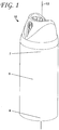
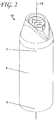
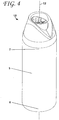
- a spray container 5 is shown in FIGS. 1-4 extending from a bottom portion 6 to a top portion 7 along an axis 12.
- An exemplary actuator apparatus 10 is coupled to the top portion 7 of the spray container 5.
- the spray container 5 e.g., a cylindrical spay can
- the spray container 5 may contain many different liquid materials such as, e.g., paint, adhesives, corrosives, lubricants, insect repellents, hairsprays, creams, edibles, foams, tear gas, pepper spray, and/or any other contents as would be known by one having ordinary skill in the art.
- the spray container 5 may be formed of any material capable of containing its contents under pressure, e.g., metals, polymers, etc.
- the spray container 5 includes a cylindrical can.
- the spray container 5 depicted in FIGS. 1-4 is cylindrical, the actuator apparatus may be operably coupled to a spray container having any shape and/or size, e.g., a square container.
- Two or more components of the actuator apparatus 10 are movable relative to each other between two or more different positions.
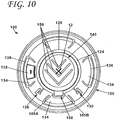
- a locked position is depicted in FIGS. 1-2 while an unlocked position is depicted in FIGS. 3-4 .
- the actuator apparatus 10 may allow a user to release at least some of the pressurized contents contained in the spray container 5.
- the actuator apparatus 10 may restrict (e.g., inhibit) a user from releasing the pressurized contents contained within the spray container 5.
- the actuator apparatus 10 may include a base 100, a cover 200, an insert 300, and a valve assembly 400.
- the valve assembly 400 may include an actuation valve 402, a flanged cup portion 404, and a tube portion 406.
- the flanged cup portion 404 may be coupled (e.g., crimped, press-fit, adhered, welded, etc.) to at least a portion of the top of the spray container 5, the tube portion 406 may extend into the interior of the spray container 5, and the actuation valve 402 may extend upward from the top of the spray container 5.
- the actuation valve 402 and flanged cup portion 404 may further include various structures to operably couple the actuation valve 402 to a portion of the base such that any pressurized contents released through the actuation valve 402 flow into a portion of the base 100 (e.g., through passageway 174 as shown in FIG. 28 ).
- the flanged cup portion 404 may include a centrally-disposed circular stepped protrusion 408 upon which the actuation valve 402 extends. Such stepped protrusion 408 may include portions having different diameters that may improve the coupling between the valve assembly 400 and the base 100.
- the components of the valve assembly 400 may be formed of the same material. In other embodiments, the components of the valve assembly 400 may be separate components coupled together.
- the actuation valve 402 may be movable to, e.g., release the pressurized contents of a spray container (e.g., spray container 5). Such movement of the actuation valve 402 may be downward depression, axially movement, etc.
- valve assembly operable by a push button as described herein to release contents of a spray container may be utilized in conjunction with the actuator apparatus 10 or variations thereof.
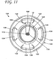
- the base 100 may include a lower portion 120 and a push button 140 (see FIGS. 6-11 ).
- the push button 140 may be depressibly attached to the lower portion 120.
- depressibly attached may refer to attachment such that the push button 140 may be depressed under normal force by a user to move the push button 140 relative to the lower portion 120.
- the lower portion 120 may include a first end region 121A and a second end region 121B located further away from the axis 12 than the first end region 121A.
- the second end region 121B may be the portion of the base 100 that is coupleable to the spray container 5 utilizing, e.g., one or more protrusions 122 (see FIG. 11 ) that may facilitate a "snap-fit" to the top of the spray container 5.
- the lower portion 120 may define a push button aperture 124 located directly below the push button 140 to facilitate downward movement of the push button 140 (e.g., such that when the push button 140 is depressed, at least a portion of the push button 140 may be located within the push button aperture 124).
- the lower portion 120 may include a bridge portion 126 connecting the lower portion 120 and the push button 140.
- the bridge portion 126 may be sized and formed of such resilient material that the push button 140 may be depressed to a depressed position (e.g., movement relative to the lower portion 120) and returned to a normal position without detaching from the lower portion 120.
- the push button 140 may be biased into the normal position such that only depression by a user may actuate the valve assembly 400 to release at least some of the pressurized contents of the spray container 5.
- the bridge portion 126 may provide such bias.
- the push button 140 may include other componentry (e.g., springs), materials (e.g., memory foam), and/or structures that may bias the push button into the normal position.
- the lower portion 120 may further include a first female locking structure 128, a second female locking structure 130, a spray opening shield portion 132, and deflectable cover retention ribs 134 that will be described herein in relation to their functions relative to the push button 140 and cover 200.
- the push button 140 may include a body potion 142, an aperture portion 160, and a receiver stem portion 170 (see FIG. 11 ). Although depicted as being cylindrical, the push button 140 may be any shape and/or size operable to be depressed by a user to actuate a valve assembly, e.g., valve assembly 400. The push button 140 may be movable relative to the lower portion 120 of the base 100 between at least a normal position and a depressed position.
- the push button 140 When the push button 140 is in the depressed position (which is only permitted when the actuator assembly is in the unlocked position), the push button 140 may actuate the actuation valve 402 of the valve assembly 400 thereby releasing at least some of the pressurized contents of the spray container 5 through, e.g., an exit aperture 162 of the aperture portion 160 of the push button 140 of the base 100.
- the valve assembly 402 When the push button 140 is in the normal position, the valve assembly 402 is not actuated and thereby no pressurized contents are released.
- the body portion 142 of the push button 140 may extend along an axis 12 of the actuator apparatus 10 from a first end region 144 that is connectable to the lower portion 120 of the base 100, e.g., via the bridge portion 126 of the lower portion 120 of the base 100, to a second end region 146 that may be contacted (e.g., depressed by a finger) by a user.
- the second end region 146 may define a sloped, concave surface 148, upon which further may be defined spray direction indicia 150 to, e.g., indicate the direction that the pressurized contents of the spray container may be released and/or whether the actuator apparatus 10 is in a locked or unlocked position.
- the sidewalls of the body 142 may cylindrical, e.g., as depicted, and further may be parallel to the axis 12 of the actuator apparatus 10.
- the aperture portion 160 may extend radially (e.g., outwardly from the axis 12 of the actuator apparatus) from a region of the body portion 142 (e.g., the side wall thereof) and may define the exit aperture 162. When the pressurized contents are released from the spray container 5, the contents may be released (e.g., sprayed) through the exit aperture 162.
- the aperture portion 160 includes an insert aperture 166 within which the insert 300 is located.
- the insert 300 may be a separately manufactured component from the base 100 or may be integral with the base 100.
- the insert 300 may be a molded feature of the aperture portion 160.
- the insert 300 may be a part of the aperture portion 160 of the push button 140 of the base 100.
- the aperture portion 160 extends along a portion of the height of the push button body portion 142.
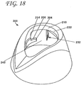
- the aperture portion 160 may have a lower surface 164 that be contacted by, e.g., a restraint structure (e.g., restraint structure 204 of FIGS. 18-19 ) to restrict the downward movement of the push button 140 as described herein.
- a restraint structure e.g., restraint structure 204 of FIGS. 18-19
- aperture portion 160 may be any size and/or shape capable of being contacted by a corresponding restraint structure (e.g., by restraint structure 204 of FIGS. 18-19 ) to restrict the movement of the push button 140.
- the aperture portion 160 is the portion of the push button 140 that may be contacted by a restraint structure (e.g., by restraint structure 204) to restrict the movement of the push button 140
- the aperture portion may be separate from the portion the may be contacted to restrict movement of the push button.
- the aperture portion may not extend from the push button body portion and instead may be flush with the exterior of the push button body.
- an additional structure may extend radially from the push button body portion to be contacted by a restraint structure to restrict the movement of the push button.
- the receiver stem portion 170 may receive the valve assembly 400 and may define an entrance aperture 172.
- a passageway 174 may be capable of transmitting gas and/or fluid and may extend from the entrance aperture 172 to the exit aperture 162 of the aperture portion 160.
- the base 100 may further include locked and unlocked indicia 102 located on various surfaces of its components to indicate to a user what state the actuator apparatus 10 is in (e.g., unlocked or locked positions).
- the indicia 102 are depictions of a "locked padlock" and an "unlocked padlock," any indicia including graphics and/or text that may be capable of indicating to a user the state of the actuator apparatus may be included on the actuator apparatus.
- the spray opening shield portion 132 may extend upwardly from the base 100 and may include such indicia 102.
- the spray opening shield portion 132 has indicia 102 indicating that the actuator apparatus 10 is in a locked state, which is only viewable to user when the actuator apparatus 10 is actually in a locked state or position as described herein.
- the spray opening shield portion 132 may not be used. Rather, the locked indicia may be provided on the push button body portion 142 such that it shows through the opening 208 when the apparatus is in a locked position.
- the cover 200 may be coupled to the base 100 and aligned along an axis 12 of the actuator apparatus 10.
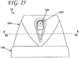
- the cover 200 may define a push button opening 202 (e.g., along axis 12) that permits access to the second end region 146 of the push button 140 to allow depression (e.g., by a finger) of the push button 140 by a user when the base 100 and the cover 200 are assembled together (see, e.g., FIGS. 1-2 , 25 , & 27-29 ).
- the cover 200 may be coupled (e.g., rotatably coupled) to the base 100 to allow movement there between. At least in one embodiment, the cover 200 is rotatable relative to the base 100 between a locked position such that the push button 140 is restricted from moving into the depressed position and an unlocked position such that the push button 140 may be allowed to move into the depressed position.
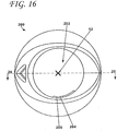
- the cover 200 may include a restraint structure 204 that restricts the push button 140 from moving into the depressed position when the base 100 and/or cover 200 is in the locked position. Further, the restraint structure 204 may define an upper surface 206 and a lower surface 209 (see FIG. 19 ).
- the restraint structure 204 may be located below the aperture portion 160 of the push button 140 of the base 100 to physically restrict the aperture portion 160 from moving downwardly, which in turn restricts the other portions of the push button 140 from moving into the depressed position.
- the upper surface 206 of the restraint structure 204 may directly contact the lower surface 164 of the aperture portion 160 of the push button 140 of the base 100 to restrict the movement of the push button 140 into the depressed position.
- the cover 200 may include one or more restraint structures. However, as depicted, the cover 200 includes only one restraint structure 204.
- the cover 200 may further define a spray opening 208 that may be alignable with the exit aperture 162 of the aperture portion 160 of the push button 140 of the base 100 when the cover 200 is in the unlocked position.
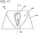
- the cover 200 may further include an inner wall portion 210 lying along the axis 12 of the actuator apparatus 10 and an outer wall portion 230 located further away from the axis 12 than the inner wall portion 210.
- the inner wall portion 210 may further include inside surface 222 and an exterior surface 224.
- the inner wall portion 210 as depicted, may by cylindrical to, e.g., define at least a portion of the push button opening 202. In other embodiments, however, the inner wall portion 210 may be any shape or size to accommodate and permit depressible movement of at least a portion of the push button 140.
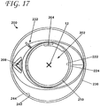
- the restraint structure 204 may be located closer to the axis 12 of the actuator apparatus 10 than the inner wall portion 210 (see FIG. 16 ).
- the inner wall portion 210 of the cover 200 may further define a first stop surface 212 and a second stop surface 214.
- the first stop surface 212 may be operable with the aperture portion 160 of the base 100 to stop the cover 200 and base 100 from moving (e.g., rotating about axis 12) past the unlocked position.
- a first side surface 165A of the aperture portion 160 may contact the first stop surface 212 to stop the cover 200 from rotating relative to the base 100.
- the aperture apparatus 10 is in the unlocked position.
- the second stop surface 214 may be operable with the aperture portion 160 of the base 100 to stop the cover 200 and base 100 from moving past the locked position.
- a second side surface 165B of the aperture portion 160 may contact the second stop surface 214 to stop the cover 200 from rotating relative to the base 100.
- the aperture apparatus 10 is in the locked position.
- the outer wall portion 230 may further define interior surface 242 and exterior surface 244. Further, the outer wall portion 230 may include a male locking structure 232 located on a portion of the interior surface 242 of the outer wall portion 230. The male locking structure 232 may engage either of the first female locking structure 128 (when in the locked position) or the second female locking structure 130 (when in the unlocked position) of the base 100 when the base 100 and the cover 200 are assembled to form the actuator apparatus 10.
- Each of the female locking structures 128, 130 may include a first rib 129A, 129B and second rib 131A, 131B, respectively.
- Each rib 129A, 129B, 131A, 131B may extend outwardly from the lower portion 120 of the base 100 for engagement with the male locking structure 232 of the outer wall portion 230 of the cover 200.
- the male locking structure 232 of the outer wall portion 230 of the cover 200 may include a deflectable portion 234 for deflectably engaging the first rib 129A of the first female locking structure 128 of the lower portion 120 of the base 100 when the cover 200 is moving into the locked position (e.g., such as to make a "click" when moving into the locked position) and for deflectably engaging the first rib 129B of the second female locking structure 130 of the lower portion 120 of the base 100 when the cover 200 is moving into the unlocked position (e.g., such as to make a "click" when moving into the unlocked position).
- a deflectable portion 234 for deflectably engaging the first rib 129A of the first female locking structure 128 of the lower portion 120 of the base 100 when the cover 200 is moving into the locked position (e.g., such as to make a "click" when moving into the locked position) and for deflectably engaging the first rib 129B of the second female locking structure 130 of the lower portion 120 of the base 100 when the cover
- the deflectable portion 234 may deflect to provide resistance to moving the cover 200 relative to the base 100 so as to signal or indicate to a user that the cover 200 may almost be moved (relative to the base 100) into either a locked or unlocked position.
- the cover 200 may be moved relative to the base 100 until the deflectable portion 234 deflects over or past one of the first ribs 129A, 129B of the first and the second female locking structures 128, 130, which provides some restriction in moving the cover 200 relative to the base 100 in the opposite direction such that a user may not inadvertently lock or unlock the actuator apparatus 100.
- the male locking structure 232 of the outer wall portion 230 of the cover may further include a rigid portion 236 for engaging the second rib 131A of the first female locking structure 128 of the base 100 when the cover 200 is moved into the locked position to stop the cover 200 from moving (e.g., relative to the base 100) past the locked position and for engaging the second rib 131B of the second female locking structure 130 of the base 100 when the cover 200 is moved into the unlocked position to stop the cover from moving (e.g., relative to the base 100) past the unlocked position.
- the rigid portion 236 may engage the second ribs 131A, 131B so as to stop the cover 200 from moving relative to the base 100 any farther.
- the male locking structure 232 may be sandwiched between either the first rib 129A and the second rib 131A of the first female locking structure 128 or the first rib 129B and the second rib 131B of the second female locking structure 130 to be partially restrained/inhibited such that a user may not inadvertently lock/unlock the actuator apparatus 100 or move (e.g., rotate) the cover 200 relative to the base 100 further past either the unlocked or locked positions.
- the cover 200 may further include an annular flange 216 located on the interior surface of the outer wall portion 230 of the cover 200 extending inwardly towards the axis 12 of the actuator apparatus 10 for use in coupling the cover 200 to the base 100 utilizing, e.g., the deflectable cover retention ribs 134 of the lower portion 120 of the base 100.
- the annular flange 216 may include an upper surface 218 (e.g., facing upwardly) and a lower surface 220 (e.g., facing downwardly), and each deflectable cover retention rib 134 may include an outer surface 136 (e.g., facing away from axis 12) and a bottom surface 138 (e.g., a surface orthogonal to axis 12).
- the base 100 and the cover 200 may be coupled together by aligning the base 100 and the cover 200 along an axis 12 with the cover 200 positioned above the base 100 (see FIG. 5 ).
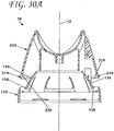
- the base 100 and cover 200 may be moved towards each such that the push button 140 of the base 100 extends at least partially into the push button aperture 124 (see FIG. 30A ).
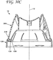
- the base 100 and the cover 200 are movable relative to each other between at least a pre-coupled position (see FIG. 30B ), where the cover 200 not yet coupled to the base 100 but in contact thereof, and a coupled position (see FIG. 30C ), where the cover 200 is coupled to the base 100.
- a pre-coupled position see FIG. 30B
- FIG. 30C When in the pre-coupled position (see FIG.
- the lower surface 220 of the annular flange 216 of the cover 200 may contact the outer surface 136 of the deflectable cover retention rib 134 to deflect the deflectable cover retention rib 134 away from its normal position.
- the cover 200 is "snapped" past the pre-coupled position.
- the upper surface 218 of the annular flange 216 of the cover 200 may engage the bottom surface 138 of the deflectable cover retention rib 134 to retain the cover 200 to the base 100.
- An annular gap 139 may further be defined between the bottom surface 138 of the cover retention rib 134 and the lower portion 120 of the base 100. The annular gap 139 may receive the annular flange 217 of the cover 200 to allow the cover and the base to move relative each other about the axis 12 of the actuator apparatus 100.
- the cover 200 and base 100 may be in the form of one or more alternate configurations to accomplish the coupling therebetween.
- the annular flange of the cover may project outward and away from axis 12 as opposed to inward and an annular retention rib of the base may extend inward towards axis 12 (e.g., at the top of the lower portion 120 of base 100) to engage the annular flange of the cover thereunder when snapped into place.
- an annular retention rib of the base may extend inward towards axis 12 (e.g., at the top of the lower portion 120 of base 100) to engage the annular flange of the cover thereunder when snapped into place.
- the upper surface 218 and the lower surface 220 of the annular flange 216 converge at a point creating an edge as depicted, the upper surface 218 and the lower surface 220 may converge in a rounded or less-steep angle such that the annular flange 216 has a rounded surface facing the axis 12 of the actuator apparatus 10.
- the base 100 and the cover 200 may be movable (e.g., rotatably movable) relative to each between the locked and unlocked positions.
- the base 100 is fixed relative to the spray container 5, and the cover 200 is rotatable relative to the base 100 between the locked and unlocked positions.
- the cover 200 is fixed relative to the spray container 5, and the base 100 is rotatable relative to the cover 200 between the locked and unlocked positions.
- the cover 200 may include additional structure to secure the cover 200 to the spray container 5 (e.g., structure that extends around the outside of the lower portion 120 of the base 100 or structure that extends through the push button aperture 124 of the base 100).
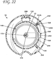
- the base 100 and cover 200 of the actuator apparatus 10 are movable relative to each other between a locked position and an unlocked position. Different views of the actuator apparatus 10 in the locked position are shown in FIGS. 21-24 . Further, different views of the actuator apparatus 10 in the unlocked position are shown in FIGS. 25-29 .
- the spray opening shield portion 132 of the base 100 may be covering at least a portion (e.g., most) of the spray opening 208 of the cover 200.
- Locked indicia 102 may be viewable through the spray opening 208 to indicate to a user that the actuator apparatus 10 is in a locked position.
- the restraint structure 204 of the cover 200 is located beneath the aperture portion 160 of the push button 140 of the base 100 to restrict the push button 140 from depression (i.e., the locked position).
- the male locking structure 232 of the cover 200 is engaged with the first female locking structure 128 of the base 100.
- the male locking structure 232 can been seen sandwiched between the first rib 129A and second rib 131A of the first female locking structure 128.
- a gap 26 may exist between the push button 140 and the inner wall portion 210 of the cover 200 as shown in FIG. 23 .
- a portion 207 of the restraint structure 204 may be seen in the gap 26 that does not extend beneath the aperture portion 160 of the push button 140 of the base 100.
- This portion 207 of the restraint structure 204 may further provide support to the restraint structure 204 and may engage the second side surface of the 165B of the aperture portion 160 of the push button 140 of the base 100 when in the locked position to, e.g., stop the base 100 and/or cover 200 from moving further past the locked position.
- this view shows that at least a portion of the restraint structure 204 may be located closer to the axis 12 of the actuator apparatus 10 than the inner wall portion 210 of the cover 200.
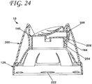
- FIG. 24 Another view of the actuator apparatus 24 in the locked position may be shown in FIG. 24 .
- the upper surface 206 of the restraint structure 204 of the cover may be shown to engage the lower surface 164 of the aperture portion 160 of the push button.
- the actuator apparatus 10 is shown in the unlocked position in FIGS. 25-29 .
- the front view of the actuator apparatus 10 as depicted in FIG. 25 shows that the aperture portion 160 may be viewable through the spray opening 208 of the cover 200 when the actuator apparatus 10 is in the unlocked position.
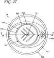
- the cross-sectional view of the actuator apparatus 10 as depicted in FIG. 26 further shows the aperture portion 160 aligned with the spray opening 208.
- the male locking structure 232 of the cover 200 is shown to be engaged with the second female locking structure 130 of the base. In this view, the male locking structure 232 can been seen sandwiched between the first rib 129B and second rib 131B of the second female locking structure 130.
- the restraint structure 204 including portion 207 may be seen in the gap 26 about a 90 degrees around the axis 12 from the spray opening 208 of the cover 200 such as to not impede or inhibit the depressible movement of the push button 140 and/or aperture portion 160.
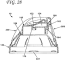
- the exit aperture 162 of the aperture 160 is aligned with the spray opening 208 (see FIG. 28 ) such that contents that may be released through the exit aperture 162 may further exit through the spray opening 208.
- the push button 140 is shown to be in the normal position as shown in FIG. 28 and in the depressed position in FIG. 29 .
- the receiver stem portion 170 of the push button 140 of the base 100 may actuate the actuation valve 402 of the valve assembly 400 (not shown in FIGS. 28-29 ) to release at least some of the pressurized contents of the spray container 5.
- the push button 140 may move (e.g., resiliently move) back to the normal position as shown in FIG. 28 .
- the push button 28 when depressed may pivot (e.g., about 1 degree to about 45 degrees) about an axis 15 extending through the bridge portion 126 of the base 100 (see FIG. 29 ). In other embodiments, the push button may move differently than pivotally, e.g., downwardly.
- bridge portion 126 of the base 100 is the portion of the base 100 that biases the push button 140 in the normal position
- additional components may be included to bias the push button 140 in the normal position (e.g., springs, memory foam, etc.).
- the components of the actuator apparatus 10, e.g., the cover 200 or base 100 may be formed of polymers, polypropylene, or any other material or combination of materials as known by one having ordinary skill in the art.
- cover 100 and the base 200 of the actuator apparatus 10 may be manufactured through any molding process as known by one having ordinary skill in the art, e.g., injection molding, transfer molding, compression molding, etc.
- the cover 100 and the base 200 may be formed using a two-piece mold.
- the components of the actuator apparatus 10 may be formed using various two or more piece molds as well as other manufacturing techniques.
- the actuator apparatus may have a base that may include a lower portion and a centrally-located push button depressibly attached to the lower portion.
- the method 600 may include providing a mold (block 602).
- the mold may define a cavity for forming the cover.
- the cover may be similar to the cover 200 shown in FIGS. 12-20 .
- the cover may define a centrally-located push button opening that permits access to the push button of the base when assembled with the base.
- the cover may include an inner wall portion lying along an axis of the actuator apparatus when assembled with the base.
- the inner wall portion of the cover may define at least a portion of the push button opening and an outer wall portion may be located a distance further away from the axis than the inner wall portion when assembled with the base.
- the outer wall portion of the cover may define a spray opening.
- the restraint structure may extend from the inner wall portion and at least a portion of that restraint structure may be located closer to the axis of the actuator apparatus when assembled than the inner wall portion of the cover.
- Providing a mold may include providing a first mold portion (block 604) and providing a second mold portion (block 606).
- the first mold portion may define a first molding surface corresponding to at least outer and inner wall portion surfaces of the cover facing a first direction and at least a lower surface of the restraint structure.
- the first molding surface may correspond to the interior surface 242 of the outer wall portion 230, the exterior surface 224 of the inner wall portion 210, and the lower surface 209 of the restraint structure 204.
- the second mold portion may define a second molding surface corresponding to at least outer and inner wall portion surfaces of the cover facing a second direction opposite from the first direction and at least an upper surface of the restraint structure.
- the first molding surface may correspond to the exterior surfaces 244 of the outer wall portion 230, the interior surface 222 of the inner wall portion 210, and the upper surface 206 of the restraint structure 204.
- the method 600 may further include positioning the first mold portion relative to the second mold portion (block 608) such that the first molding surface of the first mold portion and the second molding surface of the second mold portion define the cavity of the mold for forming the cover. Still further, the method may include introducing moldable material into the cavity of the mold (block 610) and forming the cover from the moldable material within the cavity of the mold (block 612). And still further, the method may include moving the first mold portion relative to the second mold portion for removing the cover from the cavity of the mold (block 614), and removing the cover from the cavity of the mold (block 616).
Claims (17)
- Betätigungsvorrichtung (10) für einen Sprühbehälter (5), wobei die Betätigungsvorrichtung aufweist:eine Basis (100), die aufweist:einen unteren Abschnitt (120), der mit dem Sprühbehälter koppelbar ist; undeinen Druckknopf (140), der niederdrückbar am unteren Abschnitt angebracht ist, wobei der Druckknopf aufweist:einen Körperabschnitt (142), der sich längs einer Achse (12) der Betätigungsvorrichtung zwischen einem ersten Endbereich (144), der mit dem unteren Abschnitt der Basis verbindbar ist, und einem zweiten Endbereich (146), der zum Niederdrücken des Druckknopfes durch einen Benutzer berührt werden soll, erstreckt;einen Öffnungsabschnitt (160), der sich radial von einem Bereich des Körperabschnitts erstreckt, wobei der Öffnungsabschnitt eine Austrittsöffnung definiert; und einen Aufnahmestielabschnitt (170) zum Aufnehmen einer Ventilanordnung, wobei der Aufnahmestielabschnitt eine Eintrittsöffnung definiert, wobei sich ein Fluiddurchgang zwischen der Eintrittsöffnung und der Austrittsöffnung erstreckt, wobei der Druckknopf relativ zum unteren Abschnitt der Basis zwischen mindestens einer Normalposition und einer niedergedrückten Position beweglich ist, wobei der Druckknopf die Ventilanordnung betätigt, wenn er sich in der niedergedrückten Position befindet, um einen Sprühnebel durch die Austrittsöffnung bereitzustellen; undeine Abdeckung (200), die mit der Basis gekoppelt ist, wobei die Abdeckung eine Druckknopföffnung definiert, die einen Zugang zum zweiten Endbereich des Körperabschnitts des Druckknopfes ermöglicht, um das Niederdrücken des Druckknopfs durch den Benutzer zu ermöglichen, wobei die Abdeckung und die Basis relativ zueinander zwischen mindestens einer verriegelten Position, so dass der Druckknopf an einer Bewegung in die niedergedrückte Position gehindert wird, und einer entriegelten Position, so dass es dem Druckknopf ermöglicht wird, sich in die niedergedrückte Position zu bewegen, beweglich sind, wobei die Abdeckung ferner eine Sprühöffnung definiert, die mit der Austrittsöffnung des Öffnungsabschnitts ausrichtbar ist, wenn sich die Abdekkung in der entriegelten Position befindet, wobei die Abdeckung eine Rückhaltestruktur (204) aufweist, dadurch gekennzeichnet, dass die Rückhaltestruktur tiefer als und unterhalb des Öffnungsabschnitts des Druckknopfes der Basis angeordnet ist, um den Druckknopf an einer Bewegung in die niedergedrückte Position zu hindern, wenn sich die Abdeckung in der verriegelten Position befindet.
- Betätigungsvorrichtung nach Anspruch 1, wobei eine Oberseite (206) der Rückhaltestruktur der Abdeckung eine Unterseite (164) des Öffnungsabschnitts des Druckknopfes der Basis direkt berührt, um den Druckknopf an einer Bewegung in die niedergedrückte Position zu hindern, wenn sich die Abdeckung in der verriegelten Position befindet.
- Betätigungsvorrichtung nach Anspruch 2, wobei die Abdeckung einen zylindrischen Innenwandabschnitt (210) aufweist, der längs einer Achse der Betätigungsvorrichtung verläuft und mindestens einen Abschnitt der Druckknopföffnung definiert, wobei mindestens ein Abschnitt der Rückhaltestruktur näher zur Achse der Betätigungsvorrichtung angeordnet ist als der zylindrische Innenwandabschnitt der Abdeckung.
- Betätigungsvorrichtung nach Anspruch 3, wobei der zylindrische Innenwandabschnitt der Abdeckung ferner definiert:eine erste Anschlagfläche (212) die mit dem Öffnungsabschnitt des Druckknopfes der Basis betreibbar ist, um die Abdeckung an einer Bewegung über die entriegelte Position hinaus zu hindern; undeine zweite Anschlagstruktur, die mit dem Öffnungsabschnitt des Druckknopfes der Basis betreibbar ist, um die Abdeckung an einer Bewegung über die verriegelte Position hinaus zu hindern.
- Betätigungsvorrichtung nach Anspruch 3, wobei der untere Abschnitt der Basis ferner eine erste und zweite Verriegelungsstruktur (128, 130) aufweist, wobei die Abdeckung ferner einen Außenwandabschnitt (230) aufweist, der weiter weg von der Achse der Betätigungsvorrichtung als der Innenwandabschnitt angeordnet ist, wobei der Außenwandabschnitt ferner eine männliche Verriegelungsstruktur (232) aufweist, die auf einer Innenseite des Außenwandabschnitts der Abdeckung angeordnet ist, wobei die männliche Verriegelungsstruktur des Außenwandabschnitts mit der ersten weiblichen Verriegelungsstruktur des unteren Abschnitts der Basis in Eingriff tritt, wenn sich die Abdekkung in der verriegelten Position befindet, und wobei die männliche Verriegelungsstruktur des Außenwandabschnitts der Abdeckung mit der zweiten weiblichen Verriegelungsstruktur des unteren Abschnitts der Basis in Eingriff tritt, wenn sich die Abdekkung in der entriegelten Position befindet.
- Betätigungsvorrichtung nach Anspruch 4, wobei jede weibliche Verriegelungsstruktur der ersten und zweiten weiblichen Verriegelungsstruktur des unteren Abschnitts der Basis eine erste und zweite Rippe (129A, 129B, 131A, 131B) aufweist, wobei sich jede Rippe der ersten und zweiten Rippe vom unteren Abschnitt der Basis nach außen erstreckt; und
wobei die männliche Verriegelungsstruktur des Außenwandabschnitts der Abdeckung aufweist:einen ablenkbaren Abschnitt (234) zur ablenkbaren Ineingriffnahme der ersten Rippe der ersten weiblichen Verriegelungsstruktur des unteren Abschnitts der Basis, wenn sich die Abdeckung in die verriegelte Position bewegt, und zur ablenkbaren Ineingriffnahme der ersten Rippe der zweiten weiblichen Verriegelungsstruktur des unteren Abschnitts der Basis, wenn sich die Abdeckung in die entriegelte Position bewegt; undeinen steifen Abschnitt (236) zur Ineingriffnahme der zweiten Rippe der ersten weibliche Verriegelungsstruktur der Basis, wenn die Abdeckung in die verriegelte Position bewegt wird, um die Abdeckung an einer Bewegung über die verriegelte Position hinaus zu hindern, und zur Ineingriffnahme der zweiten Rippe der zweiten weiblichen Verriegelungsstruktur der Basis, wenn die Abdeckung in die entriegelte Position bewegt wird, um die Abdeckung an einer Bewegung über die entriegelte Position hinaus zu hindern. - Betätigungsvorrichtung nach Anspruch 1, wobei der untere Abschnitt der Basis eine Druckknopföffnung (124) definiert, wobei mindestens ein Abschnitt des Körperabschnitts des Druckknopfes in der Druckknopföffnung des unteren Abschnitts der Basis angeordnet ist, wenn sich der Druckknopf in der niedergedrückten Position befindet.
- Betätigungsvorrichtung nach Anspruch 1, wobei die Basis ferner einen Sprühöffnungsabschirmungsabschnitt (132) zum Versperren der Sprühöffnung der Abdeckung aufweist, wenn sich die Abdeckung in der verriegelten Position befindet, wobei sich die Sprühöffnungsabschirmung vom unteren Abschnitt der Basis nach oben erstreckt.
- Betätigungsvorrichtung nach Anspruch 1, wobei die Abdeckung ferner aufweist:einen Innenwandabschnitt (210), der die Druckknopföffnung definiert, die längs der Achse der Betätigungsvorrichtung verläuft;einen Außenwandabschnitt (230), der weiter weg von der Achse der Betätigungsvorrichtung angeordnet ist als der Innenwandabschnitt; undeinen ringförmigen Flansch (216), der auf einer Innenseite des Außenwandabschnitts der Abdeckung angeordnet ist, der sich nach innen zur Achse der Betätigungsvorrichtung erstreckt, wobei der untere Abschnitt der Basis ferner mindestens eine ablenkbare Abdeckungshalterippe zur Ineingriffnahme des ringförmigen Flansches der Abdeckung aufweist, um die Abdeckung mit dem unteren Abschnitt der Basis zu koppeln.
- Betätigungsvorrichtung nach Anspruch 9, wobei die mindestens eine ablenkbare Abdeckungshalterippe des unteren Abschnitts der Basis einen ringförmigen Spalt (139) definiert, der sich mindestens teilweise um den unteren Abschnitt der Basis zum Aufnehmen des ringförmigen Flansches der Abdeckung erstreckt, um zu ermöglichen, dass sich die Abdeckung und die Basis relativ zueinander bewegen.
- Betätigungsvorrichtung nach Anspruch 1, wobei die Basis (100) relativ zum Sprühbehälter (5) fixiert ist, und wobei die Abdeckung (200) ferner relativ zur Basis (100) zwischen der verriegelten und entriegelten Position drehbar ist.
- Betätigungsvorrichtung nach Anspruch 1, wobei die Abdeckung (200) nur eine Rückhaltestruktur (204) aufweist.
- Betätigungsvorrichtung nach Anspruch 1, wobei der untere Abschnitt (120) der Basis (100) der Betätigungsvorrichtung mit einem Sprühbehälter (5) gekoppelt ist, und wobei der Sprühbehälter (5) ein flüssiges Material enthält.
- Betätigungsvorrichtung nach Anspruch 13, wobei das im Sprühbehälter (5) enthaltene flüssige Material Farbe aufweist.
- Verfahren (600) zum Herstellen einer Abdeckung für eine Betätigungsvorrichtung (10), die eine Basis (100) aufweist, die einen unteren Abschnitt (120) und einen zentral angeordneten Druckknopf (140) aufweist, der niederdrückbar am unteren Abschnitt angebracht ist, wobei das Herstellungsverfahren aufweist:Bereitstellen einer Form (602), die einen Hohlraum zum Bilden der Abdeckung (200) definiert, wobei die Abdeckung eine zentral angeordnete Druckknopföffnung definiert, die den Zugang zum Druckknopf der Basis ermöglicht, wenn sie mit der Basis zusammengebaut ist, wobei die Abdeckung aufweist:wobei die Form aufweist:einen Innenwandabschnitt (210), der längs einer Achse der Betätigungsvorrichtung verläuft, wenn sie mit der Basis zusammengebaut ist, wobei der Innenwandabschnitt mindestens einen Abschnitt der Druckknopföffnung definiert;einen Außenwandabschnitt (230) in einem Abstand weiter weg von der Achse als der Innenwandabschnitt, wenn sie mit der Basis zusammengebaut ist, wobei der Außenwandabschnitt eine Sprühöffnung (208) definiert; undeine Rückhaltestruktur (204), die sich vom Innenwandabschnitt erstreckt, wobei mindestens ein Abschnitt der Rückhaltestruktur näher zur Achse der Betätigungsvorrichtung angeordnet ist, wenn sie zusammengebaut ist, als der Innenwandabschnitt der Abdekkung,einen ersten Formabschnitt, der eine erste Formfläche definiert, die mindestens Außen- und Innenwandabschnittsflächen der Abdeckung, die in eine erste Richtung weisen, und mindestens einer Unterseite der Rückhaltestruktur entspricht; undeinen zweiten Formabschnitt, der eine zweite Formfläche definiert, die mindestens Außen- und Innenwandabschnittsflächen der Abdeckung, die in eine zweite Richtung weisen, die zur ersten Richtung entgegengesetzt ist, und mindestens einer Oberseite der Rückhaltestruktur entspricht;Anordnen des ersten Formabschnitts relativ zum zweiten Formabschnitt, so dass die erste Formfläche des ersten Formabschnitts und die zweite Formfläche des zweiten Formabschnitts den Hohlraum der Form zum Bilden der Abdeckung (608) definieren;Einführen eines formbaren Materials in den Hohlraum der Form (610);Bilden der Abdeckung aus dem formbaren Material innerhalb des Hohlraums der Form (612);Bewegen des ersten Formabschnitts relativ zum zweiten Formabschnitt zum Entfernen der Abdeckung aus dem Hohlraum der Form (614); undEntfernen der Abdeckung aus dem Hohlraum der Form (616).
- Verfahren nach Anspruch 15, wobei die Abdeckung (200) nur eine Rückhaltestruktur (204) aufweist.
- Verfahren nach Anspruch 15 oder 16, wobei das Bilden der Abdeckung (200) mit der Form mindestens eines von Formpressen, Spritzgießen und Transferpressen aufweist.
Priority Applications (1)
| Application Number | Priority Date | Filing Date | Title |
|---|---|---|---|
| EP18183022.5A EP3453640A1 (de) | 2008-10-06 | 2009-10-05 | Aktuator für einen sprühstoffbehälter und verfahren dafür |
Applications Claiming Priority (2)
| Application Number | Priority Date | Filing Date | Title |
|---|---|---|---|
| US10305908P | 2008-10-06 | 2008-10-06 | |
| PCT/US2009/059513 WO2010042431A1 (en) | 2008-10-06 | 2009-10-05 | Actuator for spray container and method regarding same |
Related Child Applications (2)
| Application Number | Title | Priority Date | Filing Date |
|---|---|---|---|
| EP18183022.5A Division EP3453640A1 (de) | 2008-10-06 | 2009-10-05 | Aktuator für einen sprühstoffbehälter und verfahren dafür |
| EP18183022.5A Division-Into EP3453640A1 (de) | 2008-10-06 | 2009-10-05 | Aktuator für einen sprühstoffbehälter und verfahren dafür |
Publications (3)
| Publication Number | Publication Date |
|---|---|
| EP2334575A1 EP2334575A1 (de) | 2011-06-22 |
| EP2334575A4 EP2334575A4 (de) | 2012-08-22 |
| EP2334575B1 true EP2334575B1 (de) | 2018-12-26 |
Family
ID=42100909
Family Applications (2)
| Application Number | Title | Priority Date | Filing Date |
|---|---|---|---|
| EP18183022.5A Withdrawn EP3453640A1 (de) | 2008-10-06 | 2009-10-05 | Aktuator für einen sprühstoffbehälter und verfahren dafür |
| EP09819709.8A Active EP2334575B1 (de) | 2008-10-06 | 2009-10-05 | Betätiger für einen sprühstoffbehälter und verfahren dafür |
Family Applications Before (1)
| Application Number | Title | Priority Date | Filing Date |
|---|---|---|---|
| EP18183022.5A Withdrawn EP3453640A1 (de) | 2008-10-06 | 2009-10-05 | Aktuator für einen sprühstoffbehälter und verfahren dafür |
Country Status (8)
| Country | Link |
|---|---|
| US (2) | US8622256B2 (de) |
| EP (2) | EP3453640A1 (de) |
| CN (1) | CN102171111B (de) |
| AU (1) | AU2009302618B2 (de) |
| BR (1) | BRPI0920849A2 (de) |
| CA (1) | CA2739565C (de) |
| MX (1) | MX2011003126A (de) |
| WO (1) | WO2010042431A1 (de) |
Families Citing this family (31)
| Publication number | Priority date | Publication date | Assignee | Title |
|---|---|---|---|---|
| AU2009302618B2 (en) | 2008-10-06 | 2016-04-21 | Swimc Llc | Actuator for spray container and method regarding same |
| WO2013022452A1 (en) * | 2011-08-11 | 2013-02-14 | Aptargroup, Inc. | Lockable dispensing package and actuator |
| WO2013068190A1 (en) | 2011-11-09 | 2013-05-16 | Unilever Plc | Actuator cap for a fluid dispenser |
| EP2592019B1 (de) * | 2011-11-09 | 2014-09-10 | Unilever PLC | Betätigungskappe für einen Flüssigkeitsspender |
| ES2552023T3 (es) | 2011-11-09 | 2015-11-25 | Unilever N.V. | Dispensador de aerosol |
| ES2460667T3 (es) | 2011-11-09 | 2014-05-14 | Unilever Nv | Capuchón de accionamiento para dispensador de fluidos |
| US9260237B2 (en) | 2012-12-18 | 2016-02-16 | Precision Valve Corporation | Cap for dispensing liquids or gels |
| US9962893B2 (en) | 2014-05-02 | 2018-05-08 | Preddis, Llc | Combination cap and work support system |
| JP2016130142A (ja) * | 2015-01-15 | 2016-07-21 | フマキラー株式会社 | 噴射装置 |
| USD808264S1 (en) * | 2016-01-29 | 2018-01-23 | Bayer Healthcare Llc | Bottle cap |
| USD813670S1 (en) * | 2016-01-29 | 2018-03-27 | Bayer Healthcare Llc | Bottle cap |
| USD814299S1 (en) * | 2016-01-29 | 2018-04-03 | Bayer Healthcare Llc | Bottle cap |
| USD798719S1 (en) * | 2016-01-29 | 2017-10-03 | Bayer Healthcare Llc | Bottle |
| USD818369S1 (en) * | 2016-06-14 | 2018-05-22 | Industrias Alen, S.A. De C.V. | Bottle |
| JP2018188216A (ja) * | 2017-05-12 | 2018-11-29 | 株式会社マンダム | エアゾール容器のロック機構及びこれを用いたエアゾール容器 |
| JP1598577S (de) * | 2017-06-26 | 2018-02-26 | ||
| WO2019087560A1 (ja) * | 2017-10-31 | 2019-05-09 | 株式会社吉野工業所 | エアゾール容器用吐出具 |
| US10479592B1 (en) | 2018-08-06 | 2019-11-19 | Avanti USA Ltd. | Aerosol canister case with locking twist cap |
| US10661973B1 (en) | 2018-08-06 | 2020-05-26 | Avanti USA Ltd. | Aerosol canister care with locking twist cap |
| USD892628S1 (en) | 2019-01-11 | 2020-08-11 | Albert P. Caruso | Aerosol canister case with indication ring |
| USD948608S1 (en) * | 2019-01-31 | 2022-04-12 | Hewlett-Packard Development Company, L.P. | Ink container cap |
| BR102019010372A2 (pt) * | 2019-05-21 | 2020-12-01 | Aptar Do Brasil Embalagens Ltda | Dispositivo de dispersão para fluídos pressurizados com sistema antiacionamento |
| USD947026S1 (en) * | 2020-05-22 | 2022-03-29 | Coster Tecnologie Speciali S.P.A. | Spray cap |
| USD947668S1 (en) * | 2020-05-22 | 2022-04-05 | Coster Tecnologie Speciali S.P.A. | Spray cap |
| USD938276S1 (en) * | 2020-06-01 | 2021-12-14 | S. C. Johnson & Son, Inc. | Actuator overcap |
| USD938821S1 (en) * | 2020-06-01 | 2021-12-21 | S. C. Johnson & Son, Inc. | Actuator overcap |
| USD938277S1 (en) * | 2020-06-01 | 2021-12-14 | S. C. Johnson & Son, Inc. | Actuator overcap |
| WO2021257079A1 (en) * | 2020-06-18 | 2021-12-23 | WD-40 Manufacturing Company | Aerosol actuator |
| WO2022001932A1 (zh) * | 2020-06-30 | 2022-01-06 | 微邦科技股份有限公司 | 喷雾器及储存装置 |
| EP3974345A1 (de) * | 2020-09-28 | 2022-03-30 | Aptar Radolfzell GmbH | Sprühkopf und spender mit einem solchen sprühkopf |
| US11820583B2 (en) * | 2020-12-17 | 2023-11-21 | S. C. Johnson & Son, Inc. | Double nozzle overcap assembly |
Citations (1)
| Publication number | Priority date | Publication date | Assignee | Title |
|---|---|---|---|---|
| US20080041889A1 (en) * | 2006-08-17 | 2008-02-21 | Coster Tecnologie Speciali S.P.A. | Lockable spray cap |
Family Cites Families (62)
| Publication number | Priority date | Publication date | Assignee | Title |
|---|---|---|---|---|
| US208224A (en) * | 1878-09-24 | Improvement in fertilizers | ||
| US497808A (en) * | 1893-05-23 | Arthur j | ||
| US135638A (en) * | 1873-02-11 | Improvement in trusses | ||
| US365990A (en) * | 1887-07-05 | Watch-case | ||
| US538651A (en) * | 1895-05-07 | Telegraph-key | ||
| US228547A (en) * | 1880-06-08 | Hieam s | ||
| US471106A (en) * | 1892-03-22 | Safety bank-check | ||
| US238855A (en) * | 1881-03-15 | John cliffobd | ||
| US208886A (en) * | 1878-10-15 | Improvement in smoking-pipes | ||
| US229825A (en) * | 1880-07-13 | Abnee b | ||
| US492193A (en) * | 1893-02-21 | Fastening device | ||
| US572130A (en) * | 1896-12-01 | Organ | ||
| US379433A (en) * | 1888-03-13 | Johlvt w | ||
| US457061A (en) * | 1891-08-04 | Supporting-springjbgc | ||
| US230472A (en) * | 1880-07-27 | Eugene fontaine | ||
| US436038A (en) * | 1890-09-09 | Janus | ||
| US564876A (en) * | 1896-07-28 | Guard-rail holder | ||
| US510864A (en) * | 1893-12-12 | Andrew c | ||
| US314917A (en) * | 1885-03-31 | crowson | ||
| US510865A (en) * | 1893-12-12 | Mold and process of making same | ||
| US580755A (en) * | 1897-04-13 | Thill-support | ||
| US599665A (en) * | 1898-02-22 | Reversible rotary engine | ||
| US206968A (en) * | 1878-08-13 | Improvement inthe processes of coloring photographs | ||
| US246895A (en) * | 1881-09-13 | Jhakles m | ||
| US205739A (en) * | 1878-07-09 | Improvement in combined wood and sheet-metal boxes | ||
| US3373908A (en) * | 1965-12-13 | 1968-03-19 | Johnson & Son Inc S C | Actuator cap with frangible guard |
| US3632024A (en) * | 1970-03-04 | 1972-01-04 | Union Carbide Corp | Aerosol actuator assembly having an actuator button that is rotatable between dispensing and nondispensing positions |
| US3729119A (en) * | 1971-05-11 | 1973-04-24 | Sterling Drug Inc | Childproof overcap with horizontal spray |
| US3754689A (en) * | 1971-09-01 | 1973-08-28 | Dow Chemical Co | Safety overcap for aerosol containers |
| US3848778A (en) * | 1972-08-14 | 1974-11-19 | P Meshberg | Childproof actuator assembly |
| USD246895S (en) | 1976-01-29 | 1978-01-10 | S. C. Johnson & Son, Inc. | Combined actuator and dispensing cap for a pressurized container |
| DE7712650U1 (de) | 1977-04-22 | 1977-09-08 | Kurt Vogelsang Gmbh, 6954 Hassmersheim | Schutzkappe fuer lackspruehdosen |
| FR2541749B1 (fr) * | 1983-02-25 | 1986-08-22 | Valois Sa | Dispositif d'actionnement de securite pour valve aerosol |
| USD314917S (en) | 1988-04-25 | 1991-02-26 | Sterling Drug Inc. | Combined overcap and aerosol actuator |
| JP2749640B2 (ja) * | 1989-06-30 | 1998-05-13 | ポリプラスチックス株式会社 | 樹脂製エアゾール容器 |
| US5027982A (en) * | 1990-03-29 | 1991-07-02 | S. C. Johnson & Son, Inc. | Aerosol actuator and overcap assembly |
| AU120645S (en) | 1993-11-22 | 1994-06-20 | Reckitt benckiser australia pty ltd | Integrated actuator overcap |
| US5649645A (en) * | 1995-02-15 | 1997-07-22 | S. C. Johnson & Son, Inc. | Overcap sprayer assembly |
| USD379433S (en) | 1996-03-21 | 1997-05-27 | S. C. Johnson & Son, Inc. | Aerosol overcap |
| GB9727366D0 (en) * | 1997-12-24 | 1998-02-25 | Unilever Plc | Sprayhead |
| USD436038S1 (en) | 1999-09-27 | 2001-01-09 | The Clorox Company | Actuator overcap for aerosol spray can |
| USD457061S1 (en) | 2001-03-14 | 2002-05-14 | Peter J. Walters | Dispensing cap for finger pump |
| USD471106S1 (en) | 2001-09-18 | 2003-03-04 | The Gillette Company | Aerosol actuator |
| US6769572B1 (en) * | 2001-12-27 | 2004-08-03 | Anthony Cullotta | Custom color spray paint cans |
| US6800058B2 (en) * | 2002-04-26 | 2004-10-05 | Medtronic, Inc. | System, method and apparatus for regulating vacuum supplied to surgical tools |
| US6758373B2 (en) * | 2002-05-13 | 2004-07-06 | Precision Valve Corporation | Aerosol valve actuator |
| USD510864S1 (en) | 2002-08-28 | 2005-10-25 | Rockitt Benckiser Inc. | Dispenser for an aerosol can |
| USD497808S1 (en) | 2002-08-29 | 2004-11-02 | Reckitt Benckiser Inc | Dispenser for an aerosol can |
| CN101575039B (zh) | 2003-03-03 | 2013-03-27 | 西奎斯特完美分配器外国公司 | 气溶胶促动器 |
| US8100298B2 (en) * | 2003-03-03 | 2012-01-24 | Aptargroup, Inc. | Aerosol actuator |
| USD492193S1 (en) | 2003-03-24 | 2004-06-29 | S. C. Johnson & Son, Inc. | Aerosol container and cap combination |
| USD506389S1 (en) | 2003-08-04 | 2005-06-21 | Coster Tecnologie Speciali S.P.A. | Spray cap |
| US7178694B2 (en) * | 2004-02-19 | 2007-02-20 | Saint-Gobain Calmar Inc. | Anti-clog discharge spout |
| USD538651S1 (en) | 2005-02-28 | 2007-03-20 | S.C. Johnson & Son, Inc. | Actuator cap |
| US7757905B2 (en) * | 2005-08-18 | 2010-07-20 | Summit Packaging Systems, Inc. | Spray actuator |
| US7530476B2 (en) * | 2006-04-10 | 2009-05-12 | Precision Valve Corporation | Locking aerosol dispenser |
| USD564876S1 (en) | 2006-04-20 | 2008-03-25 | S. C. Johnson & Son, Inc. | Actuator cap |
| US7588171B2 (en) * | 2006-09-12 | 2009-09-15 | Masterchem Industries Llc | Actuator for an aerosol container |
| US7699190B2 (en) * | 2007-01-04 | 2010-04-20 | Precision Valve Corporation | Locking aerosol dispenser |
| USD572130S1 (en) | 2007-05-23 | 2008-07-01 | Valspar Sourcing, Inc. | Can cover |
| USD599665S1 (en) | 2008-07-30 | 2009-09-08 | Valspar Sourcing, Inc. | Top of spray can |
| AU2009302618B2 (en) | 2008-10-06 | 2016-04-21 | Swimc Llc | Actuator for spray container and method regarding same |
-
2009
- 2009-10-05 AU AU2009302618A patent/AU2009302618B2/en active Active
- 2009-10-05 WO PCT/US2009/059513 patent/WO2010042431A1/en active Application Filing
- 2009-10-05 CA CA2739565A patent/CA2739565C/en active Active
- 2009-10-05 MX MX2011003126A patent/MX2011003126A/es active IP Right Grant
- 2009-10-05 CN CN200980139492.XA patent/CN102171111B/zh active Active
- 2009-10-05 BR BRPI0920849A patent/BRPI0920849A2/pt not_active Application Discontinuation
- 2009-10-05 EP EP18183022.5A patent/EP3453640A1/de not_active Withdrawn
- 2009-10-05 EP EP09819709.8A patent/EP2334575B1/de active Active
- 2009-10-05 US US13/121,888 patent/US8622256B2/en active Active
-
2013
- 2013-12-05 US US14/097,628 patent/US9205618B2/en active Active
Patent Citations (1)
| Publication number | Priority date | Publication date | Assignee | Title |
|---|---|---|---|---|
| US20080041889A1 (en) * | 2006-08-17 | 2008-02-21 | Coster Tecnologie Speciali S.P.A. | Lockable spray cap |
Also Published As
| Publication number | Publication date |
|---|---|
| CA2739565C (en) | 2016-10-04 |
| EP2334575A4 (de) | 2012-08-22 |
| US9205618B2 (en) | 2015-12-08 |
| AU2009302618B2 (en) | 2016-04-21 |
| AU2009302618A1 (en) | 2010-04-15 |
| US20110180570A1 (en) | 2011-07-28 |
| MX2011003126A (es) | 2011-06-21 |
| EP3453640A1 (de) | 2019-03-13 |
| CA2739565A1 (en) | 2010-04-15 |
| US8622256B2 (en) | 2014-01-07 |
| CN102171111B (zh) | 2014-05-07 |
| WO2010042431A1 (en) | 2010-04-15 |
| US20140091493A1 (en) | 2014-04-03 |
| CN102171111A (zh) | 2011-08-31 |
| BRPI0920849A2 (pt) | 2015-12-22 |
| EP2334575A1 (de) | 2011-06-22 |
Similar Documents
| Publication | Publication Date | Title |
|---|---|---|
| EP2334575B1 (de) | Betätiger für einen sprühstoffbehälter und verfahren dafür | |
| US11708210B2 (en) | Trigger overcap assembly | |
| US4353483A (en) | Container cap having safety locking means | |
| US7530476B2 (en) | Locking aerosol dispenser | |
| US7611032B2 (en) | Lockable dispensing head | |
| EP2707311B1 (de) | Verriegelbare spenderpackung und betätiger | |
| CN103459268A (zh) | 用于容器的附件机制 | |
| CN103429506A (zh) | 用于容器的附件机制 | |
| EP4043363A1 (de) | Kindersicherer aerosolbetätiger | |
| WO2012113012A1 (en) | Spray actuator | |
| US20070175899A1 (en) | Package closure | |
| GB2080884A (en) | Handle and actuating device for pressurised dispensers |
Legal Events
| Date | Code | Title | Description |
|---|---|---|---|
| PUAI | Public reference made under article 153(3) epc to a published international application that has entered the european phase |
Free format text: ORIGINAL CODE: 0009012 |
|
| 17P | Request for examination filed |
Effective date: 20110427 |
|
| AK | Designated contracting states |
Kind code of ref document: A1 Designated state(s): AT BE BG CH CY CZ DE DK EE ES FI FR GB GR HR HU IE IS IT LI LT LU LV MC MK MT NL NO PL PT RO SE SI SK SM TR |
|
| AX | Request for extension of the european patent |
Extension state: AL BA RS |
|
| DAX | Request for extension of the european patent (deleted) | ||
| A4 | Supplementary search report drawn up and despatched |
Effective date: 20120724 |
|
| RIC1 | Information provided on ipc code assigned before grant |
Ipc: B65D 83/22 20060101ALI20120718BHEP Ipc: B65D 83/20 20060101ALI20120718BHEP Ipc: B65D 83/14 20060101AFI20120718BHEP |
|
| 17Q | First examination report despatched |
Effective date: 20160418 |
|
| STAA | Information on the status of an ep patent application or granted ep patent |
Free format text: STATUS: EXAMINATION IS IN PROGRESS |
|
| GRAP | Despatch of communication of intention to grant a patent |
Free format text: ORIGINAL CODE: EPIDOSNIGR1 |
|
| STAA | Information on the status of an ep patent application or granted ep patent |
Free format text: STATUS: GRANT OF PATENT IS INTENDED |
|
| INTG | Intention to grant announced |
Effective date: 20180301 |
|
| GRAJ | Information related to disapproval of communication of intention to grant by the applicant or resumption of examination proceedings by the epo deleted |
Free format text: ORIGINAL CODE: EPIDOSDIGR1 |
|
| STAA | Information on the status of an ep patent application or granted ep patent |
Free format text: STATUS: EXAMINATION IS IN PROGRESS |
|
| INTC | Intention to grant announced (deleted) | ||
| RAP1 | Party data changed (applicant data changed or rights of an application transferred) |
Owner name: ENGINEERED POLYMER SOLUTIONS, INC. |
|
| GRAP | Despatch of communication of intention to grant a patent |
Free format text: ORIGINAL CODE: EPIDOSNIGR1 |
|
| STAA | Information on the status of an ep patent application or granted ep patent |
Free format text: STATUS: GRANT OF PATENT IS INTENDED |
|
| RAP1 | Party data changed (applicant data changed or rights of an application transferred) |
Owner name: THE VALSPAR CORPORATION |
|
| INTG | Intention to grant announced |
Effective date: 20180918 |
|
| RAP1 | Party data changed (applicant data changed or rights of an application transferred) |
Owner name: THE SHERWIN-WILLIAMS COMPANY |
|
| RAP1 | Party data changed (applicant data changed or rights of an application transferred) |
Owner name: THE SHERWIN-WILLIAMS HEADQUARTERS COMPANY |
|
| RAP1 | Party data changed (applicant data changed or rights of an application transferred) |
Owner name: SWIMC LLC |
|
| GRAS | Grant fee paid |
Free format text: ORIGINAL CODE: EPIDOSNIGR3 |
|
| GRAA | (expected) grant |
Free format text: ORIGINAL CODE: 0009210 |
|
| STAA | Information on the status of an ep patent application or granted ep patent |
Free format text: STATUS: THE PATENT HAS BEEN GRANTED |
|
| AK | Designated contracting states |
Kind code of ref document: B1 Designated state(s): AT BE BG CH CY CZ DE DK EE ES FI FR GB GR HR HU IE IS IT LI LT LU LV MC MK MT NL NO PL PT RO SE SI SK SM TR |
|
| REG | Reference to a national code |
Ref country code: GB Ref legal event code: FG4D |
|
| REG | Reference to a national code |
Ref country code: CH Ref legal event code: EP |
|
| REG | Reference to a national code |
Ref country code: AT Ref legal event code: REF Ref document number: 1081099 Country of ref document: AT Kind code of ref document: T Effective date: 20190115 |
|
| REG | Reference to a national code |
Ref country code: DE Ref legal event code: R096 Ref document number: 602009056437 Country of ref document: DE |
|
| REG | Reference to a national code |
Ref country code: IE Ref legal event code: FG4D |
|
| PG25 | Lapsed in a contracting state [announced via postgrant information from national office to epo] |
Ref country code: LV Free format text: LAPSE BECAUSE OF FAILURE TO SUBMIT A TRANSLATION OF THE DESCRIPTION OR TO PAY THE FEE WITHIN THE PRESCRIBED TIME-LIMIT Effective date: 20181226 Ref country code: FI Free format text: LAPSE BECAUSE OF FAILURE TO SUBMIT A TRANSLATION OF THE DESCRIPTION OR TO PAY THE FEE WITHIN THE PRESCRIBED TIME-LIMIT Effective date: 20181226 Ref country code: NO Free format text: LAPSE BECAUSE OF FAILURE TO SUBMIT A TRANSLATION OF THE DESCRIPTION OR TO PAY THE FEE WITHIN THE PRESCRIBED TIME-LIMIT Effective date: 20190326 Ref country code: HR Free format text: LAPSE BECAUSE OF FAILURE TO SUBMIT A TRANSLATION OF THE DESCRIPTION OR TO PAY THE FEE WITHIN THE PRESCRIBED TIME-LIMIT Effective date: 20181226 Ref country code: LT Free format text: LAPSE BECAUSE OF FAILURE TO SUBMIT A TRANSLATION OF THE DESCRIPTION OR TO PAY THE FEE WITHIN THE PRESCRIBED TIME-LIMIT Effective date: 20181226 Ref country code: BG Free format text: LAPSE BECAUSE OF FAILURE TO SUBMIT A TRANSLATION OF THE DESCRIPTION OR TO PAY THE FEE WITHIN THE PRESCRIBED TIME-LIMIT Effective date: 20190326 |
|
| REG | Reference to a national code |
Ref country code: NL Ref legal event code: MP Effective date: 20181226 |
|
| REG | Reference to a national code |
Ref country code: LT Ref legal event code: MG4D |
|
| PG25 | Lapsed in a contracting state [announced via postgrant information from national office to epo] |
Ref country code: GR Free format text: LAPSE BECAUSE OF FAILURE TO SUBMIT A TRANSLATION OF THE DESCRIPTION OR TO PAY THE FEE WITHIN THE PRESCRIBED TIME-LIMIT Effective date: 20190327 Ref country code: SE Free format text: LAPSE BECAUSE OF FAILURE TO SUBMIT A TRANSLATION OF THE DESCRIPTION OR TO PAY THE FEE WITHIN THE PRESCRIBED TIME-LIMIT Effective date: 20181226 |
|
| REG | Reference to a national code |
Ref country code: AT Ref legal event code: MK05 Ref document number: 1081099 Country of ref document: AT Kind code of ref document: T Effective date: 20181226 |
|
| PG25 | Lapsed in a contracting state [announced via postgrant information from national office to epo] |
Ref country code: NL Free format text: LAPSE BECAUSE OF FAILURE TO SUBMIT A TRANSLATION OF THE DESCRIPTION OR TO PAY THE FEE WITHIN THE PRESCRIBED TIME-LIMIT Effective date: 20181226 |
|
| PG25 | Lapsed in a contracting state [announced via postgrant information from national office to epo] |
Ref country code: ES Free format text: LAPSE BECAUSE OF FAILURE TO SUBMIT A TRANSLATION OF THE DESCRIPTION OR TO PAY THE FEE WITHIN THE PRESCRIBED TIME-LIMIT Effective date: 20181226 Ref country code: PT Free format text: LAPSE BECAUSE OF FAILURE TO SUBMIT A TRANSLATION OF THE DESCRIPTION OR TO PAY THE FEE WITHIN THE PRESCRIBED TIME-LIMIT Effective date: 20190426 Ref country code: PL Free format text: LAPSE BECAUSE OF FAILURE TO SUBMIT A TRANSLATION OF THE DESCRIPTION OR TO PAY THE FEE WITHIN THE PRESCRIBED TIME-LIMIT Effective date: 20181226 Ref country code: CZ Free format text: LAPSE BECAUSE OF FAILURE TO SUBMIT A TRANSLATION OF THE DESCRIPTION OR TO PAY THE FEE WITHIN THE PRESCRIBED TIME-LIMIT Effective date: 20181226 Ref country code: IT Free format text: LAPSE BECAUSE OF FAILURE TO SUBMIT A TRANSLATION OF THE DESCRIPTION OR TO PAY THE FEE WITHIN THE PRESCRIBED TIME-LIMIT Effective date: 20181226 |
|
| PG25 | Lapsed in a contracting state [announced via postgrant information from national office to epo] |
Ref country code: RO Free format text: LAPSE BECAUSE OF FAILURE TO SUBMIT A TRANSLATION OF THE DESCRIPTION OR TO PAY THE FEE WITHIN THE PRESCRIBED TIME-LIMIT Effective date: 20181226 Ref country code: IS Free format text: LAPSE BECAUSE OF FAILURE TO SUBMIT A TRANSLATION OF THE DESCRIPTION OR TO PAY THE FEE WITHIN THE PRESCRIBED TIME-LIMIT Effective date: 20190426 Ref country code: SK Free format text: LAPSE BECAUSE OF FAILURE TO SUBMIT A TRANSLATION OF THE DESCRIPTION OR TO PAY THE FEE WITHIN THE PRESCRIBED TIME-LIMIT Effective date: 20181226 Ref country code: EE Free format text: LAPSE BECAUSE OF FAILURE TO SUBMIT A TRANSLATION OF THE DESCRIPTION OR TO PAY THE FEE WITHIN THE PRESCRIBED TIME-LIMIT Effective date: 20181226 Ref country code: SM Free format text: LAPSE BECAUSE OF FAILURE TO SUBMIT A TRANSLATION OF THE DESCRIPTION OR TO PAY THE FEE WITHIN THE PRESCRIBED TIME-LIMIT Effective date: 20181226 |
|
| REG | Reference to a national code |
Ref country code: DE Ref legal event code: R097 Ref document number: 602009056437 Country of ref document: DE |
|
| PG25 | Lapsed in a contracting state [announced via postgrant information from national office to epo] |
Ref country code: DK Free format text: LAPSE BECAUSE OF FAILURE TO SUBMIT A TRANSLATION OF THE DESCRIPTION OR TO PAY THE FEE WITHIN THE PRESCRIBED TIME-LIMIT Effective date: 20181226 Ref country code: AT Free format text: LAPSE BECAUSE OF FAILURE TO SUBMIT A TRANSLATION OF THE DESCRIPTION OR TO PAY THE FEE WITHIN THE PRESCRIBED TIME-LIMIT Effective date: 20181226 |
|
| PLBE | No opposition filed within time limit |
Free format text: ORIGINAL CODE: 0009261 |
|
| STAA | Information on the status of an ep patent application or granted ep patent |
Free format text: STATUS: NO OPPOSITION FILED WITHIN TIME LIMIT |
|
| 26N | No opposition filed |
Effective date: 20190927 |
|
| PG25 | Lapsed in a contracting state [announced via postgrant information from national office to epo] |
Ref country code: SI Free format text: LAPSE BECAUSE OF FAILURE TO SUBMIT A TRANSLATION OF THE DESCRIPTION OR TO PAY THE FEE WITHIN THE PRESCRIBED TIME-LIMIT Effective date: 20181226 |
|
| PG25 | Lapsed in a contracting state [announced via postgrant information from national office to epo] |
Ref country code: TR Free format text: LAPSE BECAUSE OF FAILURE TO SUBMIT A TRANSLATION OF THE DESCRIPTION OR TO PAY THE FEE WITHIN THE PRESCRIBED TIME-LIMIT Effective date: 20181226 |
|
| PG25 | Lapsed in a contracting state [announced via postgrant information from national office to epo] |
Ref country code: MC Free format text: LAPSE BECAUSE OF FAILURE TO SUBMIT A TRANSLATION OF THE DESCRIPTION OR TO PAY THE FEE WITHIN THE PRESCRIBED TIME-LIMIT Effective date: 20181226 |
|
| REG | Reference to a national code |
Ref country code: CH Ref legal event code: PL |
|
| PG25 | Lapsed in a contracting state [announced via postgrant information from national office to epo] |
Ref country code: CH Free format text: LAPSE BECAUSE OF NON-PAYMENT OF DUE FEES Effective date: 20191031 Ref country code: LI Free format text: LAPSE BECAUSE OF NON-PAYMENT OF DUE FEES Effective date: 20191031 Ref country code: LU Free format text: LAPSE BECAUSE OF NON-PAYMENT OF DUE FEES Effective date: 20191005 |
|
| REG | Reference to a national code |
Ref country code: BE Ref legal event code: MM Effective date: 20191031 |
|
| PG25 | Lapsed in a contracting state [announced via postgrant information from national office to epo] |
Ref country code: BE Free format text: LAPSE BECAUSE OF NON-PAYMENT OF DUE FEES Effective date: 20191031 |
|
| PG25 | Lapsed in a contracting state [announced via postgrant information from national office to epo] |
Ref country code: IE Free format text: LAPSE BECAUSE OF NON-PAYMENT OF DUE FEES Effective date: 20191005 |
|
| PG25 | Lapsed in a contracting state [announced via postgrant information from national office to epo] |
Ref country code: CY Free format text: LAPSE BECAUSE OF FAILURE TO SUBMIT A TRANSLATION OF THE DESCRIPTION OR TO PAY THE FEE WITHIN THE PRESCRIBED TIME-LIMIT Effective date: 20181226 |
|
| PG25 | Lapsed in a contracting state [announced via postgrant information from national office to epo] |
Ref country code: MT Free format text: LAPSE BECAUSE OF FAILURE TO SUBMIT A TRANSLATION OF THE DESCRIPTION OR TO PAY THE FEE WITHIN THE PRESCRIBED TIME-LIMIT Effective date: 20181226 Ref country code: HU Free format text: LAPSE BECAUSE OF FAILURE TO SUBMIT A TRANSLATION OF THE DESCRIPTION OR TO PAY THE FEE WITHIN THE PRESCRIBED TIME-LIMIT; INVALID AB INITIO Effective date: 20091005 |
|
| PGFP | Annual fee paid to national office [announced via postgrant information from national office to epo] |
Ref country code: FR Payment date: 20211025 Year of fee payment: 13 |
|
| PG25 | Lapsed in a contracting state [announced via postgrant information from national office to epo] |
Ref country code: MK Free format text: LAPSE BECAUSE OF FAILURE TO SUBMIT A TRANSLATION OF THE DESCRIPTION OR TO PAY THE FEE WITHIN THE PRESCRIBED TIME-LIMIT Effective date: 20181226 |
|
| P01 | Opt-out of the competence of the unified patent court (upc) registered |
Effective date: 20230601 |
|
| PG25 | Lapsed in a contracting state [announced via postgrant information from national office to epo] |
Ref country code: FR Free format text: LAPSE BECAUSE OF NON-PAYMENT OF DUE FEES Effective date: 20221031 |
|
| PGFP | Annual fee paid to national office [announced via postgrant information from national office to epo] |
Ref country code: GB Payment date: 20231027 Year of fee payment: 15 |
|
| PGFP | Annual fee paid to national office [announced via postgrant information from national office to epo] |
Ref country code: DE Payment date: 20231027 Year of fee payment: 15 |