EP2333296A1 - Ventilelement für eine Flüssigkeitsventilanordnung - Google Patents
Ventilelement für eine Flüssigkeitsventilanordnung Download PDFInfo
- Publication number
- EP2333296A1 EP2333296A1 EP09178743A EP09178743A EP2333296A1 EP 2333296 A1 EP2333296 A1 EP 2333296A1 EP 09178743 A EP09178743 A EP 09178743A EP 09178743 A EP09178743 A EP 09178743A EP 2333296 A1 EP2333296 A1 EP 2333296A1
- Authority
- EP
- European Patent Office
- Prior art keywords
- valve member
- outer edge
- edge region
- region
- valve
- Prior art date
- Legal status (The legal status is an assumption and is not a legal conclusion. Google has not performed a legal analysis and makes no representation as to the accuracy of the status listed.)
- Granted
Links
- 239000012530 fluid Substances 0.000 title description 5
- 239000000446 fuel Substances 0.000 claims abstract description 48
- 238000002485 combustion reaction Methods 0.000 claims abstract description 13
- 230000007704 transition Effects 0.000 claims description 7
- 238000000576 coating method Methods 0.000 description 15
- 239000011248 coating agent Substances 0.000 description 13
- 238000002347 injection Methods 0.000 description 11
- 239000007924 injection Substances 0.000 description 11
- 230000008901 benefit Effects 0.000 description 8
- 238000005553 drilling Methods 0.000 description 7
- 238000004519 manufacturing process Methods 0.000 description 7
- 230000002093 peripheral effect Effects 0.000 description 7
- 230000000694 effects Effects 0.000 description 5
- 238000000034 method Methods 0.000 description 5
- 238000013016 damping Methods 0.000 description 4
- 239000000463 material Substances 0.000 description 3
- 150000004767 nitrides Chemical class 0.000 description 3
- 230000036316 preload Effects 0.000 description 3
- OKTJSMMVPCPJKN-UHFFFAOYSA-N Carbon Chemical compound [C] OKTJSMMVPCPJKN-UHFFFAOYSA-N 0.000 description 2
- 230000009286 beneficial effect Effects 0.000 description 2
- 229910052799 carbon Inorganic materials 0.000 description 2
- 238000005229 chemical vapour deposition Methods 0.000 description 2
- 229910003460 diamond Inorganic materials 0.000 description 2
- 239000010432 diamond Substances 0.000 description 2
- 238000005240 physical vapour deposition Methods 0.000 description 2
- 230000008569 process Effects 0.000 description 2
- 229910000831 Steel Inorganic materials 0.000 description 1
- 230000004913 activation Effects 0.000 description 1
- 230000015572 biosynthetic process Effects 0.000 description 1
- 230000000295 complement effect Effects 0.000 description 1
- 230000006835 compression Effects 0.000 description 1
- 238000007906 compression Methods 0.000 description 1
- 238000011109 contamination Methods 0.000 description 1
- 230000001627 detrimental effect Effects 0.000 description 1
- 239000002283 diesel fuel Substances 0.000 description 1
- 230000007613 environmental effect Effects 0.000 description 1
- 230000006872 improvement Effects 0.000 description 1
- 230000000977 initiatory effect Effects 0.000 description 1
- 238000002955 isolation Methods 0.000 description 1
- 238000003801 milling Methods 0.000 description 1
- 238000002156 mixing Methods 0.000 description 1
- 239000000203 mixture Substances 0.000 description 1
- 230000004048 modification Effects 0.000 description 1
- 238000012986 modification Methods 0.000 description 1
- 238000010008 shearing Methods 0.000 description 1
- 239000007787 solid Substances 0.000 description 1
- 239000010959 steel Substances 0.000 description 1
- 230000035899 viability Effects 0.000 description 1
Images


Classifications
-
- F—MECHANICAL ENGINEERING; LIGHTING; HEATING; WEAPONS; BLASTING
- F02—COMBUSTION ENGINES; HOT-GAS OR COMBUSTION-PRODUCT ENGINE PLANTS
- F02M—SUPPLYING COMBUSTION ENGINES IN GENERAL WITH COMBUSTIBLE MIXTURES OR CONSTITUENTS THEREOF
- F02M47/00—Fuel-injection apparatus operated cyclically with fuel-injection valves actuated by fluid pressure
- F02M47/02—Fuel-injection apparatus operated cyclically with fuel-injection valves actuated by fluid pressure of accumulator-injector type, i.e. having fuel pressure of accumulator tending to open, and fuel pressure in other chamber tending to close, injection valves and having means for periodically releasing that closing pressure
- F02M47/027—Electrically actuated valves draining the chamber to release the closing pressure
-
- F—MECHANICAL ENGINEERING; LIGHTING; HEATING; WEAPONS; BLASTING
- F02—COMBUSTION ENGINES; HOT-GAS OR COMBUSTION-PRODUCT ENGINE PLANTS
- F02M—SUPPLYING COMBUSTION ENGINES IN GENERAL WITH COMBUSTIBLE MIXTURES OR CONSTITUENTS THEREOF
- F02M63/00—Other fuel-injection apparatus having pertinent characteristics not provided for in groups F02M39/00 - F02M57/00 or F02M67/00; Details, component parts, or accessories of fuel-injection apparatus, not provided for in, or of interest apart from, the apparatus of groups F02M39/00 - F02M61/00 or F02M67/00; Combination of fuel pump with other devices, e.g. lubricating oil pump
- F02M63/0012—Valves
- F02M63/0031—Valves characterized by the type of valves, e.g. special valve member details, valve seat details, valve housing details
-
- F—MECHANICAL ENGINEERING; LIGHTING; HEATING; WEAPONS; BLASTING
- F02—COMBUSTION ENGINES; HOT-GAS OR COMBUSTION-PRODUCT ENGINE PLANTS
- F02M—SUPPLYING COMBUSTION ENGINES IN GENERAL WITH COMBUSTIBLE MIXTURES OR CONSTITUENTS THEREOF
- F02M2200/00—Details of fuel-injection apparatus, not otherwise provided for
- F02M2200/04—Fuel-injection apparatus having means for avoiding effect of cavitation, e.g. erosion
Definitions
- This invention relates to a control valve arrangement for use in controlling fluid pressure within a control chamber.
- the invention relates to a control valve arrangement for use in controlling fluid pressure within a control chamber forming part of a fuel injector of an internal combustion engine.
- such a control valve arrangement includes a control valve member which is movable between a first position, in which fuel under high pressure is able to flow into the control chamber, and a second position in which the control chamber communicates with a low pressure fuel reservoir.
- a surface associated with the valve needle is exposed to fuel pressure within the control chamber such that the pressure of fuel within the control chamber applies a force to the valve needle to urge the valve needle against its seating.
- valve arrangement In order to commence injection, the valve arrangement is actuated such that the control valve member is moved into its second position, thereby causing fuel pressure within the control chamber to be reduced. The force urging the valve needle against its seating is therefore reduced and fuel pressure within the delivery chamber serves to lift the valve needle away from its seating to permit fuel to flow through the injector outlet.
- valve arrangement In order to terminate injection, the valve arrangement is actuated such that the control valve member is moved into its first position, thereby permitting fuel under high pressure to flow into the control chamber. The force acting on the valve needle due to fuel pressure within the control chamber is therefore increased, causing the valve needle to be urged against its seating to terminate injection.
- the fuel injectors used therein should be capable of delivering very small quantities of fuel over a wide range of fuel pressures, and up to pressures in the region of 3000 bar.
- the valves for use in injectors at these pressures tend to be smaller and hence present manufacturing difficulties. As a result, features on such valves tend to be a compromise between performance and manufacturing capability.
- the invention provides a valve member suitable for use in a fuel injector in an internal combustion engine, the valve member having an end face including an outer edge region defining an annular seat for engaging a seating surface, in use, and which encloses a generally spheroidal recessed inner region.
- the invention extends to a valve arrangement including a valve housing defining a seating surface with which the seat of the valve member is arranged to be engageable, in use.
- the generally spheroidal recess of the inner region enables the 'dead volume' of the valve member, that is to say the volume under the end face, to be significantly reduced compared to known valve member configurations which reduces the likelihood of cavitation damage occurring as the valve member is lifted from its seating surface, in use.
- the recessed inner region has a depth defined substantially along the longitudinal axis of the valve member, wherein the ratio of the depth to the diameter of the valve member is in the range of 1:35 to 1:65.
- the outer edge region is also generally spheroidal and has shallower curvature than the curvature of the recessed inner region.
- outer edge region has a greater radius of curvature than the inner region. Arranging the outer and inner regions in this way enables the dead volume to be minimised within manufacturing limitations, and also lends itself to efficient manufacturing techniques since the inner region can be formed in a first step in which a significant amount of material is removed from the valve member, and then, in a second step, the outer spheroidal region is formed.
- the outer edge region is a frustoconical surface that defines an angle in the range of 0.5 to 5 degrees, and preferably 1.5 degrees, with a plane normal to a longitudinal axis of the valve member.
- the outer edge region has a length defined along a plane normal to the longitudinal axis of the valve member, wherein the ratio of the length of the outer edge region to the diameter of the valve member is in the range of between 1:25 and 1:35, and preferably 1:28.
- the shallow incline of the outer edge region results in a hydraulic 'squeeze effect' in use - expressed in another way, fluid, for example diesel fuel, is squeezed between the outer edge region of the valve member and its seating surface when the valve member is forced into engagement with the seating surface.
- fluid for example diesel fuel
- this provides a damping force to reduce the closing velocity of the valve member, thereby lessening the impact force generated between the valve member and the seating surface which reduces valve damage.
- This feature is particularly beneficial in fast acting valves operating at high fluid pressures, for example in high-pressure diesel injection systems in which injection pressures can exceed 3000bar, where the impact forces are generally higher than in lower pressure applications.
- the transition between the outer edge region and the recessed inner region may be blended so as to avoid sharp geometric lines of intersection so as to be smooth or burr-free. Therefore, the cross-section of the end face of the valve member can be described as curvilinear. This feature also enhances adherence of a hardened coating that may be applied to the underside of the valve member since such coatings tend to be sensitive to sharp surface discontinuities so a smooth profile is desirable.
- the invention provides a valve member suitable for use in a fuel injector in an internal combustion engine, the valve member having an end region defining an outer wall and an end face, wherein a frustoconical surface connects the outer wall and the end face, and wherein a seating line is defined at an intersection between the frustoconical surface and an outer edge region of the end face.
- the frustoconical transition (in other words, angled or bevelled) between the outer wall of the valve member and the end face provides the advantage of improving the adhesion potential of a hardened coating, for example a Diamond Like Carbon (DLC) or other such coating known in the art that may be applied by physical or chemical vapour deposition processes. Therefore, the valve member of the invention including this feature is more hardwearing than known valve members.
- a hardened coating for example a Diamond Like Carbon (DLC) or other such coating known in the art that may be applied by physical or chemical vapour deposition processes. Therefore, the valve member of the invention including this feature is more hardwearing than known valve members.
- DLC Diamond Like Carbon
- the frustoconical outer surface defines an angle of 45 degrees to the longitudinal axis of the valve member, which provides the optimum balance between ease of manufacturing, durability of the seating line and improvement of coating adhesion.
- a range of angles between 5 and 50 degrees would also provide a significant benefit, being a compromise between functionality and manufacturing.
- the invention also resides is a control valve arrangement including a valve housing within which a valve member as described above is slidable and including a seating surface with which an end of the valve member is engageable.
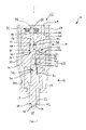
- a fuel injector 10 comprises an injector nozzle 12 and a three-way nozzle control valve arrangement (NCV) 14.
- An injector body 16 sits between the injector nozzle 12 and the control valve arrangement 14, and all three components are housed within a generally tubular injector housing 17, also known in the art as a 'cap nut'.
- the nozzle 12 comprises a nozzle body 22 that defines a blind bore 20 within which a elongate nozzle needle 18 is slidably received.
- a lower end 24 of the nozzle needle 18 terminates in a nozzle tip and is engageable with a first needle seat 26 defined by the blind end of the bore 20 so as to control fuel delivery through a set of outlet openings 28 provided in the nozzle body 22 into a combustion space 27.
- the nozzle needle 18 is shown in Figure 1 disengaged from the needle seat 26 for clarity.
- the nozzle 12 also includes a spring 30 received on the nozzle needle 18 which abuts the nozzle body 16 and acts on a spring seat 31 attached to the nozzle needle 18 so as to bias it towards the first needle seat 26.
- Fuel under high pressure is delivered from a fuel supply to an enlarged region 20a of the nozzle bore 20, in use, through a supply passage 32 defined, in part, by the various components of the injector 10, as will be described in more detail below.
- An upper end 34 of the nozzle needle 18, remote from the outlet openings 28, is slidable within a cylindrical guide bore 36 in the injector body 16.
- the upper end 34 is also referred to as the "needle piston".
- a control chamber 38 is located axially in line and above the needle piston 34 in the orientation shown in Figure 1 .
- the control chamber 38 is defined in part by the cylindrical guide bore 36 and in part by an end surface 40 of the needle piston 34.
- Fuel pressure within the control chamber 38 applies a force to the end surface 40 of the nozzle needle 18, which serves to urge the nozzle needle 18 against the first needle seat 26 to prevent fuel injection through the outlet openings 28.
- a force is applied to a thrust surface 42 of the nozzle needle 18 which serves to urge the nozzle needle 18 away from the first needle seat 26.
- the force acting on the thrust surface 42 due to fuel pressure within the nozzle chamber 20 in addition to the force from the gas pressure in the combustion chamber 27 acting on the needle tip is sufficient to overcome the force acting on the end surface 40 of the nozzle needle 18, and the force on the nozzle needle 18 provided by the spring 30 (the spring pre-load force), such that the nozzle needle 18 lifts away from the first needle seat 26 to commence fuel injection.
- the spring pre-load force the force on the nozzle needle 18 lifts away from the first needle seat 26 to commence fuel injection.
- the pressure of fuel within the control chamber 38 is controlled by means of the control valve arrangement 14.
- the control valve arrangement 14 includes a pin-like valve member 44 which is slidable within a valve guide bore 46 defined in a valve housing 48, which sits atop of and abuts the injector body 16.
- the injector body 16 is provided with a first drilling 50 which defines a flow passage from the control chamber 38 to the valve guide bore 46 via a further drilling 51 provided in the valve housing 48.
- the injector body also defines a lateral drilling 52 that defines a second flow passage leading from the lower end of the valve guide bore to the peripheral outer wall of the injector body where a drain chamber 53 is defined by the injector housing 17, the drain chamber being at a low pressure level.
- An upper end face 54 of the injector body 16 defines a first valve seat 56 with which a lower end region 57 of the valve member 44 is engaged when the valve member 44 is moved into a first position.
- the valve guide bore 46 is also shaped to define a second valve seat 58 with which a surface of the valve member 44 is engaged when it is moved upwardly into a second position.
- Movement of the valve member 44 is controlled by means of an electromagnetic actuator arrangement 62 housed within an actuator housing 64.
- the actuator housing 64 abuts the valve housing 48, both housings 48, 64 being provided with respective drillings 66, 68 which connect to a respective drilling 65 in the injector body 16 and, thus, form part of the supply passage 32 to the nozzle chamber 20.
- the valve housing 48 also defines an intermediate passage 70 that connects the supply passage 32 with an upper annulus 71 in the valve guide bore 46.
- the electromagnetic actuator arrangement 62 includes an electromagnet 72 that is located in the actuator housing 64 so as to be in close proximity to an armature 74 affixed to an upper end of the valve member 44. Activation of the electromagnet 72 attracts the armature thereby lifting the valve member 44 upwardly in an axial direction.
- a helical compression spring 76 is located in a spring chamber 78 of the actuator housing 64 which acts on the upper end of the valve member 44 to ensure that the valve member 44 is biased into engagement with the first valve seat 56, in circumstances where the electromagnet 72 is de-energised.
- valve member 44 within the valve guide bore 46 may also be controlled by other means that would be apparent to the skilled person, for example by a piezoelectric actuator or a magnetorestrictive actuator.
- control valve arrangement 14 In use, when the control valve arrangement 14 is de-energised, that is when the valve member 44 is in its first position such that a lower end thereof is in engagement with the first valve seat 56, fuel at high pressure is able to flow from the supply passage 32 through the intermediate passage 70 defined in the valve housing 48 into the annulus 71 of the valve guide bore 46, past the second valve seat 58 and through the drillings 50 and 51 into the control chamber 38 thereby pressurising the control chamber 38.
- the nozzle needle 18 is urged against the first needle seat 26 because the net downward force on the nozzle needle 18 provided by the pressurised fuel in the control chamber 38 acting on the end surface 40 of the nozzle needle 18, in combination with the spring pre-load force, is greater than the net upward force on the nozzle needle 18 provided by the pressurised fuel in the nozzle chamber 20 acting on the thrust surface 42 of the nozzle needle 18 in combination with the force exerted on the nozzle needle tip by pressurised gas in the combustion space 27.
- fuel injection through the outlet openings 28 does not occur.
- control valve arrangement 14 is energised such that the valve member 44 is moved away from the first valve seat 56 into engagement with the second valve seat 58, such that fuel within the supply passage 32 is no longer able to flow past the second valve seat 58 to the control chamber 38. Instead, fuel within the control chamber 38 is able to flow through the flow passage 50, past the lower end region 57 of the valve member and, subsequently, the first valve seat 56 and through the second flow passage 52 to the low pressure fuel reservoir. Fuel pressure within the control chamber 38 is therefore reduced or, in other words, the control chamber 38 is depressurised.
- the nozzle needle 18 is urged away from the first needle seat 26 due to the force of fuel pressure within the nozzle chamber 20 acting on the thrust surface 42 of the nozzle needle 18 being sufficient to overcome the reduced force acting on the end surface 40 of the nozzle needle 18 and the spring pre-load force, and high pressure fuel is delivered through the outlets 28 into the combustion space 27. Termination of an injection event is achieved by de-activating the actuator arrangement 62.
- FIGS. 2a and 2b show the lower end region 57 of the valve member 44 in greater detail than in Figure 1 so that the geometrical features of the valve member 44 are clearly apparent.
- the lower end region 57 of the valve member 44 is generally a solid metallic cylinder, for example of steel, and defines a cylindrical wall 59 and lower end face 80 that is engageable with the valve seating 56 (not shown in Figures 2a and 2b ).
- the lower end region 57 and the lower end face 80 comprise several beneficial features, as will now be explained.
- a common technique to improve the durability of valve members in general is to apply a hard coating, for example a Diamond Like Carbon (DLC) or nitride coating to the end region of the valve member via either a physical or chemical vapour deposition process as are known in the art.
- a hard coating for example a Diamond Like Carbon (DLC) or nitride coating
- DLC Diamond Like Carbon
- nitride coating to the end region of the valve member via either a physical or chemical vapour deposition process as are known in the art.
- known valve members having such coatings are susceptible to wear in certain circumstances, particularly when the impact loads of the valve members are increased, as can occur when operating pressures are in the region of 3000 bar, for example.
- the distal end of the lower end region 57 is shaped to define a frustoconical annular shoulder 82 at an oblique angle to the axis 'A' of the valve member 44, the shoulder 82 connecting the wall 59 and the end face 80.
- the shoulder 82 defines a 45 degree angle to the axis A.
- frustoconical shoulder 82 has been observed to improve the adhesion of the hardened coating to the underlying surface of the valve member, and particularly the region of the valve member that contact the seating surface in use, so that it is less likely to abrade during use.
- an angle of 45 degrees is currently preferred, it is envisaged that any angle within the range of 5 to 50 degrees is also suitable and would provide a durability benefit.
- the lower end face 80 is dished so as to define a shallow depression or recess 84, as can be viewed most clearly in Figure 2b .
- the recess 84 is generally circular in profile when viewed in the direction of the end face 80 and extends at a shallow angle so as to define a circular seating line 90 where the recess 84 intersects the frustoconical shoulder.
- the seating line 90 serves to engage the seating surface 56, in use.
- the recess 84 is defined by two regions: a central (or inner) region 84b, and a peripheral (or outer) edge region 84a, the radius of curvature of the inner region 84b being less than the outer region 84a.
- the shallowness of the recess 84 results in a much lower 'dead volume' underneath the valve member compared to known valve members, for instance as exemplified by EP03762755 , which includes a centre drilling formed as part of a manufacturing process.
- the comparatively small dead volume lessens the severity of cavitation damage that may otherwise occur at high operating pressures as the valve member 44 is retracted from its seat 56, which therefore has the benefit of improving the durability of the valve member 44 and, more specifically, the durability of the seating line 90 defined at the periphery of the recess 84.
- a suitable range for the depth 'd' of the recess 84b compared to the diameter D of the valve member is between approximately 1:35 and 1:65 when expressed as a ratio (i.e. between approximately 1.5% and 3% of the diameter of the end region 57).
- the end region 57 may be manufactured such that the inner region 84b is formed first, for example by milling, which removes a significant volume of material. Following this, the outer peripheral region 84a may be formed.
- the advantage of this technique is that the inner region, which can tolerate having a relatively rough finish may be formed, so a large volume of material can be removed relatively rapidly. The relatively shallow outer region can then be formed with a finer finish.
- FIG. 3a and 3b an alternative embodiment of the invention is shown in which features similar to those in Figures 2a and 2b are denoted by like reference numerals.
- the lower end region 57 of the valve member 44 retains the annular shoulder 82 of the embodiment of Figures 2a and 2b .
- the lower end face 84 also includes a cavitation-reducing recess 100 which has a curvilinear profile, in cross-section, instead of the distinct inner and outer radiussed regions (84b, 84a in Figures 2a and 2b .
- an outer peripheral edge region 100a (also shown inset for clarity) is a frustoconical surface defining an angle ⁇ 2 of preferably 1.5 degrees with a plane normal to the major axis A-A of the valve member 44. Moving radially inwards from the outer peripheral region 100a, the recess blends into a generally spherical inner or central region 100b. Expressed another way, the lower end face 84 of the valve member 44 is shaped to define a curvilinear profile, free from sharp geometric transitions.
- blending between the outer peripheral portion 100a and the central region 100b avoids the formation of any geometrical transitions in the end face, therefore avoiding the possibility of such transitions wearing/chipping during use which would present a possible risk of fuel contamination.
- the smooth profile of the recess 100 also improves the adherence of a hardened coating (e.g. DLC or nitride) that may be applied to the underside of the valve member.
- the benefit of the shallow angle ⁇ 2 defined by the outer region 100a is to provide a hydrodynamic damping effect as the lower end face 84 of the valve member 44 comes into contact with a seating surface 56 in use.
- 1.5 degrees is presently preferred as striking a balance between reducing cavitation within the recess 100 as a whole and providing an sufficient damping effect upon valve member seating, it is envisaged that a range of angles between 0.5 and 5 degrees will also provide acceptable results.
- a further benefit is that the shallow angle improve the adherence of a hardened coating applied to the underside of the valve member since such a coating will experience less stress than compared to an angled surface.
- a hardened coating e.g. DLC or nitride
- the horizontal length component of the peripheral region 100a is selected to be long enough to provide a sufficient damping effect but not so long as to introduce unwanted flow restrictions to the valve member at small valve lifts.
- the Applicant has determined that an optimum range for the length L 1 compared to the diameter of the valve member 44 is between 1:25 and 1:35 (or between about 3% an 4% when expressed as a percentage), whilst a ratio of 1:28 has been observed as particularly effective.
Priority Applications (1)
| Application Number | Priority Date | Filing Date | Title |
|---|---|---|---|
| EP20090178743 EP2333296B1 (de) | 2009-12-10 | 2009-12-10 | Ventilelement für eine Flüssigkeitsventilanordnung |
Applications Claiming Priority (1)
| Application Number | Priority Date | Filing Date | Title |
|---|---|---|---|
| EP20090178743 EP2333296B1 (de) | 2009-12-10 | 2009-12-10 | Ventilelement für eine Flüssigkeitsventilanordnung |
Publications (2)
| Publication Number | Publication Date |
|---|---|
| EP2333296A1 true EP2333296A1 (de) | 2011-06-15 |
| EP2333296B1 EP2333296B1 (de) | 2013-04-17 |
Family
ID=41831050
Family Applications (1)
| Application Number | Title | Priority Date | Filing Date |
|---|---|---|---|
| EP20090178743 Active EP2333296B1 (de) | 2009-12-10 | 2009-12-10 | Ventilelement für eine Flüssigkeitsventilanordnung |
Country Status (1)
| Country | Link |
|---|---|
| EP (1) | EP2333296B1 (de) |
Cited By (3)
| Publication number | Priority date | Publication date | Assignee | Title |
|---|---|---|---|---|
| EP1865189A2 (de) * | 2006-06-07 | 2007-12-12 | Robert Bosch Gmbh | Kraftstoffinjektor mit einem niederdruckseitig angeordneten Piezosteller |
| EP2711537A1 (de) * | 2012-09-25 | 2014-03-26 | Delphi International Operations Luxembourg S.a.r.l. | Kraftstoffeinspritzdüse |
| WO2018036786A1 (en) * | 2016-08-25 | 2018-03-01 | Delphi Technologies Ip Limited | Control valve assembly of a fuel injector |
Citations (4)
| Publication number | Priority date | Publication date | Assignee | Title |
|---|---|---|---|---|
| EP0781913A2 (de) * | 1995-12-23 | 1997-07-02 | LUCAS INDUSTRIES public limited company | Ventilanordnung |
| EP1600627A1 (de) * | 2004-05-15 | 2005-11-30 | L'orange Gmbh | Steuerventil |
| EP1865189A2 (de) * | 2006-06-07 | 2007-12-12 | Robert Bosch Gmbh | Kraftstoffinjektor mit einem niederdruckseitig angeordneten Piezosteller |
| WO2008046679A1 (de) * | 2006-10-18 | 2008-04-24 | Robert Bosch Gmbh | Injektor zum einspritzen von kraftstoff |
-
2009
- 2009-12-10 EP EP20090178743 patent/EP2333296B1/de active Active
Patent Citations (4)
| Publication number | Priority date | Publication date | Assignee | Title |
|---|---|---|---|---|
| EP0781913A2 (de) * | 1995-12-23 | 1997-07-02 | LUCAS INDUSTRIES public limited company | Ventilanordnung |
| EP1600627A1 (de) * | 2004-05-15 | 2005-11-30 | L'orange Gmbh | Steuerventil |
| EP1865189A2 (de) * | 2006-06-07 | 2007-12-12 | Robert Bosch Gmbh | Kraftstoffinjektor mit einem niederdruckseitig angeordneten Piezosteller |
| WO2008046679A1 (de) * | 2006-10-18 | 2008-04-24 | Robert Bosch Gmbh | Injektor zum einspritzen von kraftstoff |
Cited By (5)
| Publication number | Priority date | Publication date | Assignee | Title |
|---|---|---|---|---|
| EP1865189A2 (de) * | 2006-06-07 | 2007-12-12 | Robert Bosch Gmbh | Kraftstoffinjektor mit einem niederdruckseitig angeordneten Piezosteller |
| EP1865189B1 (de) * | 2006-06-07 | 2012-10-03 | Robert Bosch Gmbh | Kraftstoffinjektor mit einem niederdruckseitig angeordneten Piezosteller |
| EP2711537A1 (de) * | 2012-09-25 | 2014-03-26 | Delphi International Operations Luxembourg S.a.r.l. | Kraftstoffeinspritzdüse |
| WO2014048605A1 (en) * | 2012-09-25 | 2014-04-03 | Delphi International Operations Luxembourg S.À.R.L. | Fuel injector |
| WO2018036786A1 (en) * | 2016-08-25 | 2018-03-01 | Delphi Technologies Ip Limited | Control valve assembly of a fuel injector |
Also Published As
| Publication number | Publication date |
|---|---|
| EP2333296B1 (de) | 2013-04-17 |
Similar Documents
| Publication | Publication Date | Title |
|---|---|---|
| US8919677B2 (en) | Injection nozzle | |
| US7971802B2 (en) | Fuel injector | |
| EP1382836B1 (de) | Kraftstoffeinspritzventil | |
| EP1965070B1 (de) | Kraftstoffeinspritzventil | |
| CN101680413B (zh) | 用于燃料喷射阀的控制阀 | |
| US20110180634A1 (en) | Nozzle body, nozzle assembly and fuel injector, and method for producing a nozzle body | |
| US20070261673A1 (en) | Fuel Injector with Punch-Formed Valve Seat for Reducing Armature Stroke Drift | |
| JPH06229347A (ja) | 電磁燃料噴射弁 | |
| EP1757803B1 (de) | Einspritzdüse | |
| US20060157582A1 (en) | Fuel injector reducing stress concentration | |
| US7568634B2 (en) | Injection nozzle | |
| EP2333296B1 (de) | Ventilelement für eine Flüssigkeitsventilanordnung | |
| US20150114353A1 (en) | Injection nozzle | |
| EP0985821A2 (de) | Brennstoffeinspritzventil | |
| EP1245822B1 (de) | Einspritzventil mit einem Durchflussbegrenzer in dem Steuerventil | |
| EP1621759B1 (de) | Common-Rail-Injektor | |
| US6454189B1 (en) | Reverse acting nozzle valve and fuel injector using same | |
| GB2336628A (en) | A fuel injector, for an I.C. engine, having a three way two position needle control valve | |
| CN101360909A (zh) | 燃料喷射器 | |
| WO2010053020A1 (ja) | 蓄圧式燃料噴射装置の制御弁構造 | |
| EP1180596B1 (de) | Einspritzdüse | |
| GB2318387A (en) | I.c. engine fuel-injector with outwardly opening valve member and hydraulic damping of the opening stroke | |
| CN1856642A (zh) | 用于控制高压流体系统中的、尤其是用于内燃机的燃料喷射装置中的连接的阀 | |
| JP4297041B2 (ja) | 燃料噴射ノズル | |
| JPH07293387A (ja) | 電磁燃料噴射弁 |
Legal Events
| Date | Code | Title | Description |
|---|---|---|---|
| PUAI | Public reference made under article 153(3) epc to a published international application that has entered the european phase |
Free format text: ORIGINAL CODE: 0009012 |
|
| AK | Designated contracting states |
Kind code of ref document: A1 Designated state(s): AT BE BG CH CY CZ DE DK EE ES FI FR GB GR HR HU IE IS IT LI LT LU LV MC MK MT NL NO PL PT RO SE SI SK SM TR |
|
| AX | Request for extension of the european patent |
Extension state: AL BA RS |
|
| 17P | Request for examination filed |
Effective date: 20111215 |
|
| RIC1 | Information provided on ipc code assigned before grant |
Ipc: F02M 59/46 20060101ALI20120802BHEP Ipc: F02M 63/00 20060101ALI20120802BHEP Ipc: F02M 47/02 20060101AFI20120802BHEP |
|
| GRAP | Despatch of communication of intention to grant a patent |
Free format text: ORIGINAL CODE: EPIDOSNIGR1 |
|
| GRAS | Grant fee paid |
Free format text: ORIGINAL CODE: EPIDOSNIGR3 |
|
| GRAA | (expected) grant |
Free format text: ORIGINAL CODE: 0009210 |
|
| AK | Designated contracting states |
Kind code of ref document: B1 Designated state(s): AT BE BG CH CY CZ DE DK EE ES FI FR GB GR HR HU IE IS IT LI LT LU LV MC MK MT NL NO PL PT RO SE SI SK SM TR |
|
| AX | Request for extension of the european patent |
Extension state: AL BA RS |
|
| REG | Reference to a national code |
Ref country code: GB Ref legal event code: FG4D |
|
| REG | Reference to a national code |
Ref country code: CH Ref legal event code: EP |
|
| REG | Reference to a national code |
Ref country code: IE Ref legal event code: FG4D |
|
| REG | Reference to a national code |
Ref country code: AT Ref legal event code: REF Ref document number: 607452 Country of ref document: AT Kind code of ref document: T Effective date: 20130515 |
|
| REG | Reference to a national code |
Ref country code: DE Ref legal event code: R096 Ref document number: 602009014994 Country of ref document: DE Effective date: 20130613 |
|
| REG | Reference to a national code |
Ref country code: AT Ref legal event code: MK05 Ref document number: 607452 Country of ref document: AT Kind code of ref document: T Effective date: 20130417 |
|
| REG | Reference to a national code |
Ref country code: LT Ref legal event code: MG4D |
|
| REG | Reference to a national code |
Ref country code: NL Ref legal event code: VDEP Effective date: 20130417 |
|
| PG25 | Lapsed in a contracting state [announced via postgrant information from national office to epo] |
Ref country code: LT Free format text: LAPSE BECAUSE OF FAILURE TO SUBMIT A TRANSLATION OF THE DESCRIPTION OR TO PAY THE FEE WITHIN THE PRESCRIBED TIME-LIMIT Effective date: 20130417 Ref country code: BE Free format text: LAPSE BECAUSE OF FAILURE TO SUBMIT A TRANSLATION OF THE DESCRIPTION OR TO PAY THE FEE WITHIN THE PRESCRIBED TIME-LIMIT Effective date: 20130417 Ref country code: IS Free format text: LAPSE BECAUSE OF FAILURE TO SUBMIT A TRANSLATION OF THE DESCRIPTION OR TO PAY THE FEE WITHIN THE PRESCRIBED TIME-LIMIT Effective date: 20130817 Ref country code: SE Free format text: LAPSE BECAUSE OF FAILURE TO SUBMIT A TRANSLATION OF THE DESCRIPTION OR TO PAY THE FEE WITHIN THE PRESCRIBED TIME-LIMIT Effective date: 20130417 Ref country code: AT Free format text: LAPSE BECAUSE OF FAILURE TO SUBMIT A TRANSLATION OF THE DESCRIPTION OR TO PAY THE FEE WITHIN THE PRESCRIBED TIME-LIMIT Effective date: 20130417 Ref country code: PT Free format text: LAPSE BECAUSE OF FAILURE TO SUBMIT A TRANSLATION OF THE DESCRIPTION OR TO PAY THE FEE WITHIN THE PRESCRIBED TIME-LIMIT Effective date: 20130819 Ref country code: NO Free format text: LAPSE BECAUSE OF FAILURE TO SUBMIT A TRANSLATION OF THE DESCRIPTION OR TO PAY THE FEE WITHIN THE PRESCRIBED TIME-LIMIT Effective date: 20130717 Ref country code: SI Free format text: LAPSE BECAUSE OF FAILURE TO SUBMIT A TRANSLATION OF THE DESCRIPTION OR TO PAY THE FEE WITHIN THE PRESCRIBED TIME-LIMIT Effective date: 20130417 Ref country code: GR Free format text: LAPSE BECAUSE OF FAILURE TO SUBMIT A TRANSLATION OF THE DESCRIPTION OR TO PAY THE FEE WITHIN THE PRESCRIBED TIME-LIMIT Effective date: 20130718 Ref country code: FI Free format text: LAPSE BECAUSE OF FAILURE TO SUBMIT A TRANSLATION OF THE DESCRIPTION OR TO PAY THE FEE WITHIN THE PRESCRIBED TIME-LIMIT Effective date: 20130417 Ref country code: ES Free format text: LAPSE BECAUSE OF FAILURE TO SUBMIT A TRANSLATION OF THE DESCRIPTION OR TO PAY THE FEE WITHIN THE PRESCRIBED TIME-LIMIT Effective date: 20130728 |
|
| PG25 | Lapsed in a contracting state [announced via postgrant information from national office to epo] |
Ref country code: CY Free format text: LAPSE BECAUSE OF FAILURE TO SUBMIT A TRANSLATION OF THE DESCRIPTION OR TO PAY THE FEE WITHIN THE PRESCRIBED TIME-LIMIT Effective date: 20130417 Ref country code: LV Free format text: LAPSE BECAUSE OF FAILURE TO SUBMIT A TRANSLATION OF THE DESCRIPTION OR TO PAY THE FEE WITHIN THE PRESCRIBED TIME-LIMIT Effective date: 20130417 Ref country code: HR Free format text: LAPSE BECAUSE OF FAILURE TO SUBMIT A TRANSLATION OF THE DESCRIPTION OR TO PAY THE FEE WITHIN THE PRESCRIBED TIME-LIMIT Effective date: 20130417 Ref country code: PL Free format text: LAPSE BECAUSE OF FAILURE TO SUBMIT A TRANSLATION OF THE DESCRIPTION OR TO PAY THE FEE WITHIN THE PRESCRIBED TIME-LIMIT Effective date: 20130417 Ref country code: BG Free format text: LAPSE BECAUSE OF FAILURE TO SUBMIT A TRANSLATION OF THE DESCRIPTION OR TO PAY THE FEE WITHIN THE PRESCRIBED TIME-LIMIT Effective date: 20130717 |
|
| PG25 | Lapsed in a contracting state [announced via postgrant information from national office to epo] |
Ref country code: SK Free format text: LAPSE BECAUSE OF FAILURE TO SUBMIT A TRANSLATION OF THE DESCRIPTION OR TO PAY THE FEE WITHIN THE PRESCRIBED TIME-LIMIT Effective date: 20130417 Ref country code: CZ Free format text: LAPSE BECAUSE OF FAILURE TO SUBMIT A TRANSLATION OF THE DESCRIPTION OR TO PAY THE FEE WITHIN THE PRESCRIBED TIME-LIMIT Effective date: 20130417 Ref country code: DK Free format text: LAPSE BECAUSE OF FAILURE TO SUBMIT A TRANSLATION OF THE DESCRIPTION OR TO PAY THE FEE WITHIN THE PRESCRIBED TIME-LIMIT Effective date: 20130417 Ref country code: EE Free format text: LAPSE BECAUSE OF FAILURE TO SUBMIT A TRANSLATION OF THE DESCRIPTION OR TO PAY THE FEE WITHIN THE PRESCRIBED TIME-LIMIT Effective date: 20130417 |
|
| PLBE | No opposition filed within time limit |
Free format text: ORIGINAL CODE: 0009261 |
|
| STAA | Information on the status of an ep patent application or granted ep patent |
Free format text: STATUS: NO OPPOSITION FILED WITHIN TIME LIMIT |
|
| PG25 | Lapsed in a contracting state [announced via postgrant information from national office to epo] |
Ref country code: NL Free format text: LAPSE BECAUSE OF FAILURE TO SUBMIT A TRANSLATION OF THE DESCRIPTION OR TO PAY THE FEE WITHIN THE PRESCRIBED TIME-LIMIT Effective date: 20130417 Ref country code: RO Free format text: LAPSE BECAUSE OF FAILURE TO SUBMIT A TRANSLATION OF THE DESCRIPTION OR TO PAY THE FEE WITHIN THE PRESCRIBED TIME-LIMIT Effective date: 20130417 |
|
| 26N | No opposition filed |
Effective date: 20140120 |
|
| REG | Reference to a national code |
Ref country code: DE Ref legal event code: R097 Ref document number: 602009014994 Country of ref document: DE Effective date: 20140120 |
|
| REG | Reference to a national code |
Ref country code: FR Ref legal event code: TP Owner name: DELPHI INTERNATIONAL OPERATIONS LUXEMBOURG S.A, LU Effective date: 20140516 |
|
| REG | Reference to a national code |
Ref country code: CH Ref legal event code: PL |
|
| REG | Reference to a national code |
Ref country code: DE Ref legal event code: R081 Ref document number: 602009014994 Country of ref document: DE Owner name: DELPHI INTERNATIONAL OPERATIONS LUXEMBOURG S.A, LU Free format text: FORMER OWNER: DELPHI TECHNOLOGIES HOLDING S.A.R.L., BASCHARAGE, LU Effective date: 20140715 |
|
| GBPC | Gb: european patent ceased through non-payment of renewal fee |
Effective date: 20131210 |
|
| PG25 | Lapsed in a contracting state [announced via postgrant information from national office to epo] |
Ref country code: LU Free format text: LAPSE BECAUSE OF FAILURE TO SUBMIT A TRANSLATION OF THE DESCRIPTION OR TO PAY THE FEE WITHIN THE PRESCRIBED TIME-LIMIT Effective date: 20131210 Ref country code: MC Free format text: LAPSE BECAUSE OF FAILURE TO SUBMIT A TRANSLATION OF THE DESCRIPTION OR TO PAY THE FEE WITHIN THE PRESCRIBED TIME-LIMIT Effective date: 20130417 |
|
| REG | Reference to a national code |
Ref country code: IE Ref legal event code: MM4A |
|
| PG25 | Lapsed in a contracting state [announced via postgrant information from national office to epo] |
Ref country code: LI Free format text: LAPSE BECAUSE OF NON-PAYMENT OF DUE FEES Effective date: 20131231 Ref country code: IE Free format text: LAPSE BECAUSE OF NON-PAYMENT OF DUE FEES Effective date: 20131210 Ref country code: CH Free format text: LAPSE BECAUSE OF NON-PAYMENT OF DUE FEES Effective date: 20131231 |
|
| PG25 | Lapsed in a contracting state [announced via postgrant information from national office to epo] |
Ref country code: GB Free format text: LAPSE BECAUSE OF NON-PAYMENT OF DUE FEES Effective date: 20131210 |
|
| PG25 | Lapsed in a contracting state [announced via postgrant information from national office to epo] |
Ref country code: SM Free format text: LAPSE BECAUSE OF FAILURE TO SUBMIT A TRANSLATION OF THE DESCRIPTION OR TO PAY THE FEE WITHIN THE PRESCRIBED TIME-LIMIT Effective date: 20130417 |
|
| PG25 | Lapsed in a contracting state [announced via postgrant information from national office to epo] |
Ref country code: TR Free format text: LAPSE BECAUSE OF FAILURE TO SUBMIT A TRANSLATION OF THE DESCRIPTION OR TO PAY THE FEE WITHIN THE PRESCRIBED TIME-LIMIT Effective date: 20130417 |
|
| PG25 | Lapsed in a contracting state [announced via postgrant information from national office to epo] |
Ref country code: MK Free format text: LAPSE BECAUSE OF FAILURE TO SUBMIT A TRANSLATION OF THE DESCRIPTION OR TO PAY THE FEE WITHIN THE PRESCRIBED TIME-LIMIT Effective date: 20130417 Ref country code: HU Free format text: LAPSE BECAUSE OF FAILURE TO SUBMIT A TRANSLATION OF THE DESCRIPTION OR TO PAY THE FEE WITHIN THE PRESCRIBED TIME-LIMIT; INVALID AB INITIO Effective date: 20091210 |
|
| PG25 | Lapsed in a contracting state [announced via postgrant information from national office to epo] |
Ref country code: MT Free format text: LAPSE BECAUSE OF FAILURE TO SUBMIT A TRANSLATION OF THE DESCRIPTION OR TO PAY THE FEE WITHIN THE PRESCRIBED TIME-LIMIT Effective date: 20130417 |
|
| REG | Reference to a national code |
Ref country code: FR Ref legal event code: PLFP Year of fee payment: 7 |
|
| REG | Reference to a national code |
Ref country code: FR Ref legal event code: PLFP Year of fee payment: 8 |
|
| PG25 | Lapsed in a contracting state [announced via postgrant information from national office to epo] |
Ref country code: IT Free format text: LAPSE BECAUSE OF NON-PAYMENT OF DUE FEES Effective date: 20151210 |
|
| PG25 | Lapsed in a contracting state [announced via postgrant information from national office to epo] |
Ref country code: IT Free format text: LAPSE BECAUSE OF NON-PAYMENT OF DUE FEES Effective date: 20151210 |
|
| PGRI | Patent reinstated in contracting state [announced from national office to epo] |
Ref country code: IT Effective date: 20170710 |
|
| REG | Reference to a national code |
Ref country code: FR Ref legal event code: PLFP Year of fee payment: 9 |
|
| REG | Reference to a national code |
Ref country code: DE Ref legal event code: R081 Ref document number: 602009014994 Country of ref document: DE Owner name: DELPHI TECHNOLOGIES IP LIMITED, BB Free format text: FORMER OWNER: DELPHI INTERNATIONAL OPERATIONS LUXEMBOURG S.A R.L., BASCHARAGE, LU |
|
| PGFP | Annual fee paid to national office [announced via postgrant information from national office to epo] |
Ref country code: IT Payment date: 20201221 Year of fee payment: 12 |
|
| P01 | Opt-out of the competence of the unified patent court (upc) registered |
Effective date: 20230327 |
|
| PG25 | Lapsed in a contracting state [announced via postgrant information from national office to epo] |
Ref country code: IT Free format text: LAPSE BECAUSE OF NON-PAYMENT OF DUE FEES Effective date: 20211231 |
|
| PGFP | Annual fee paid to national office [announced via postgrant information from national office to epo] |
Ref country code: FR Payment date: 20231108 Year of fee payment: 15 Ref country code: DE Payment date: 20231108 Year of fee payment: 15 |
|
| REG | Reference to a national code |
Ref country code: DE Ref legal event code: R081 Ref document number: 602009014994 Country of ref document: DE Owner name: PHINIA DELPHI LUXEMBOURG SARL, LU Free format text: FORMER OWNER: DELPHI TECHNOLOGIES IP LIMITED, ST. MICHAEL, BB |